

Page 1
User Manual
enPuls
Version 2.0
USA
Page 2
Figures
1
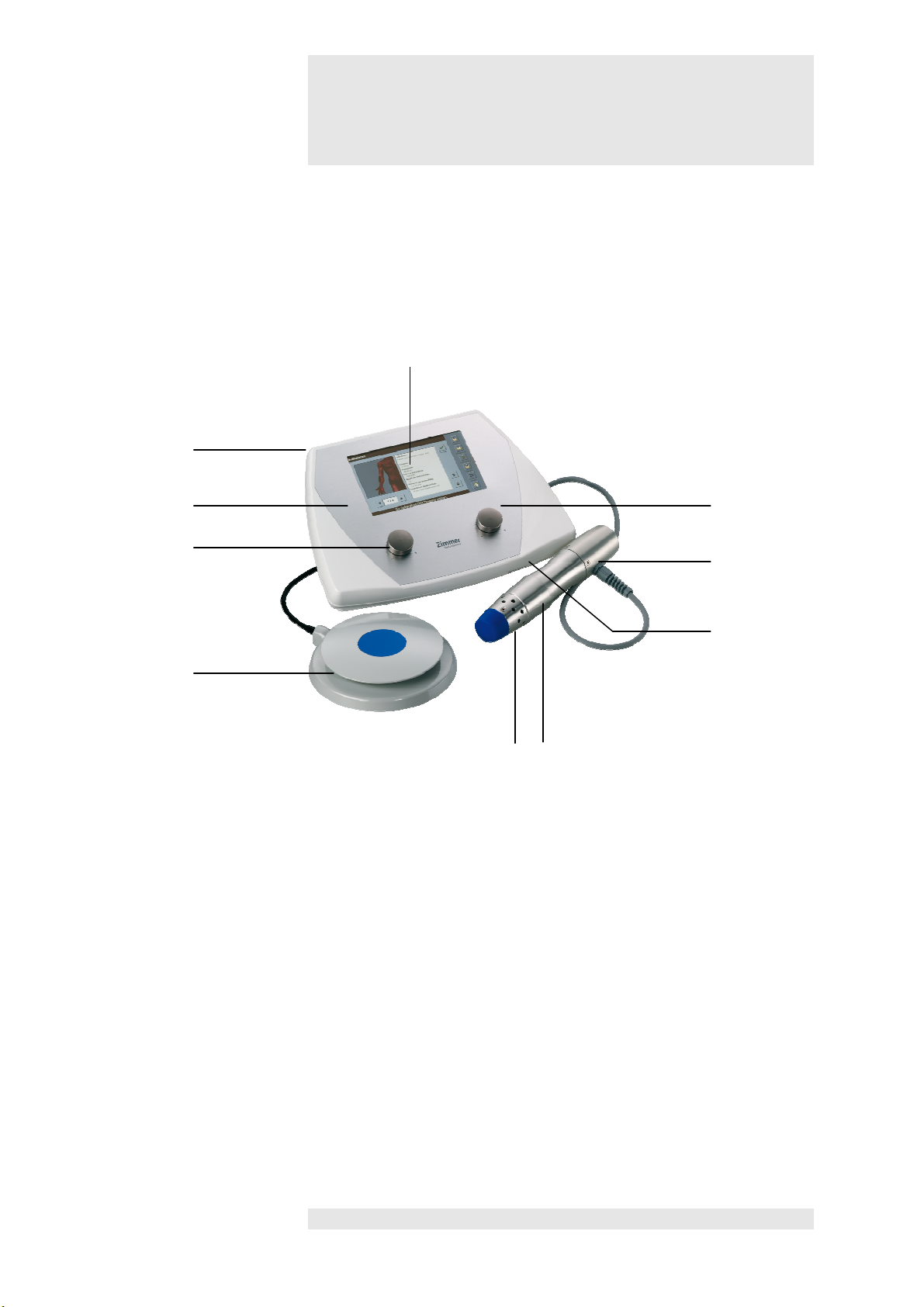
Control unit / Handpiece / Footswitch
Selection and control
1
Control unit
Handpiece
7
Handpiece with
applicator head 25 mm
Footswitch
10
Footswitch
Front view of device
4
3
1
2
5
9
10
elements
8
2 Pulse energy controller
3 Touch pen in holder
4 Display
5 Frequency controller
6 SD card slot
8 Air vents, front
9 Air vents with fan, rear
6
7
Page 3
Figures
2
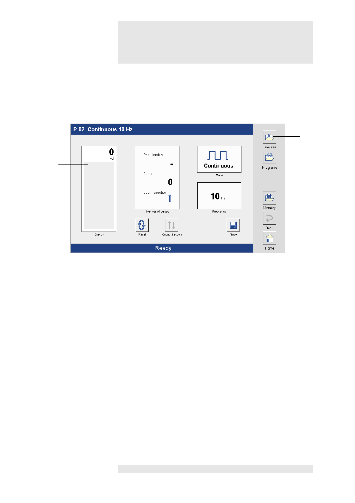
Display
Screen readouts
11
Status bar
Front view of device
12
13
14
11
12 Screen controls
13 Title bar
14 Navigation bar
Page 4
Figures
3
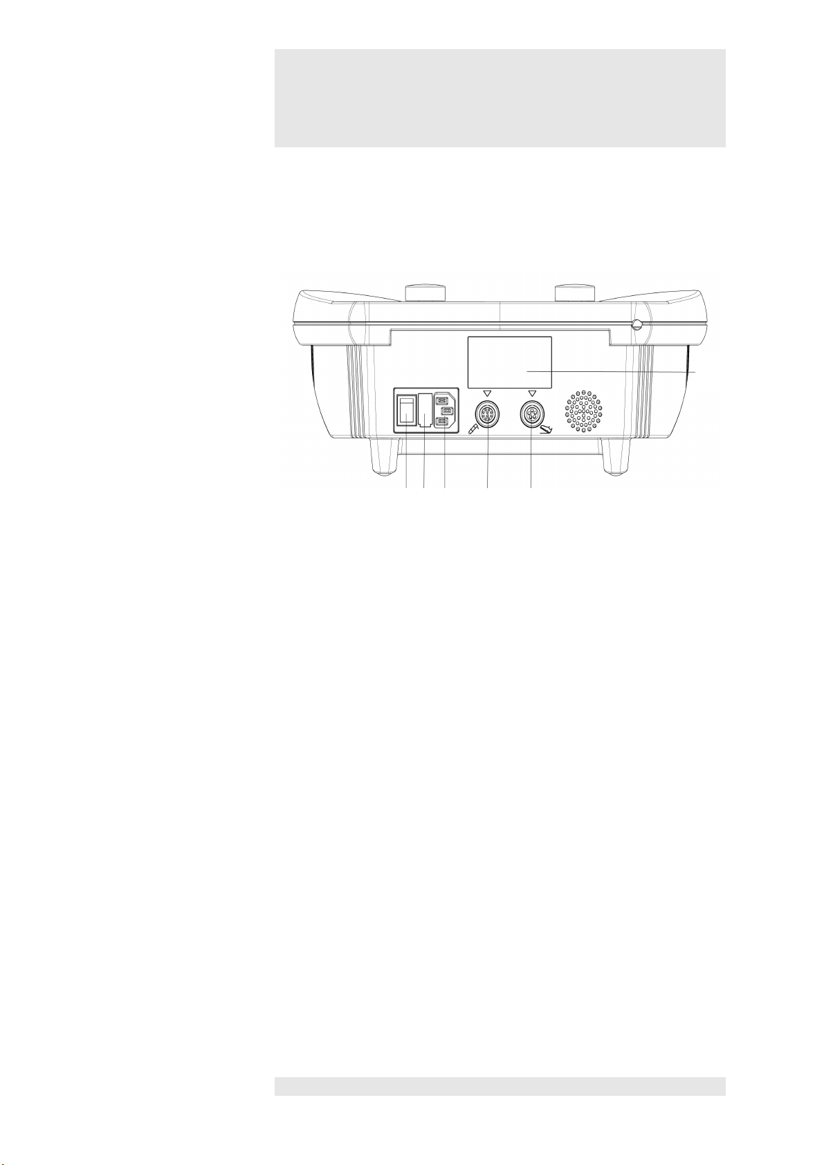
Switch and connector sockets
Switch /
15 Main switch
Rear view of device
20
15 16 17 18 19
Connector sockets
16 Mains fuse
17 Port for mains cable
18 Port for handpiece
19 Port for footswitch
20 Serial number / manufacturer's plate
Page 5
Figures
4
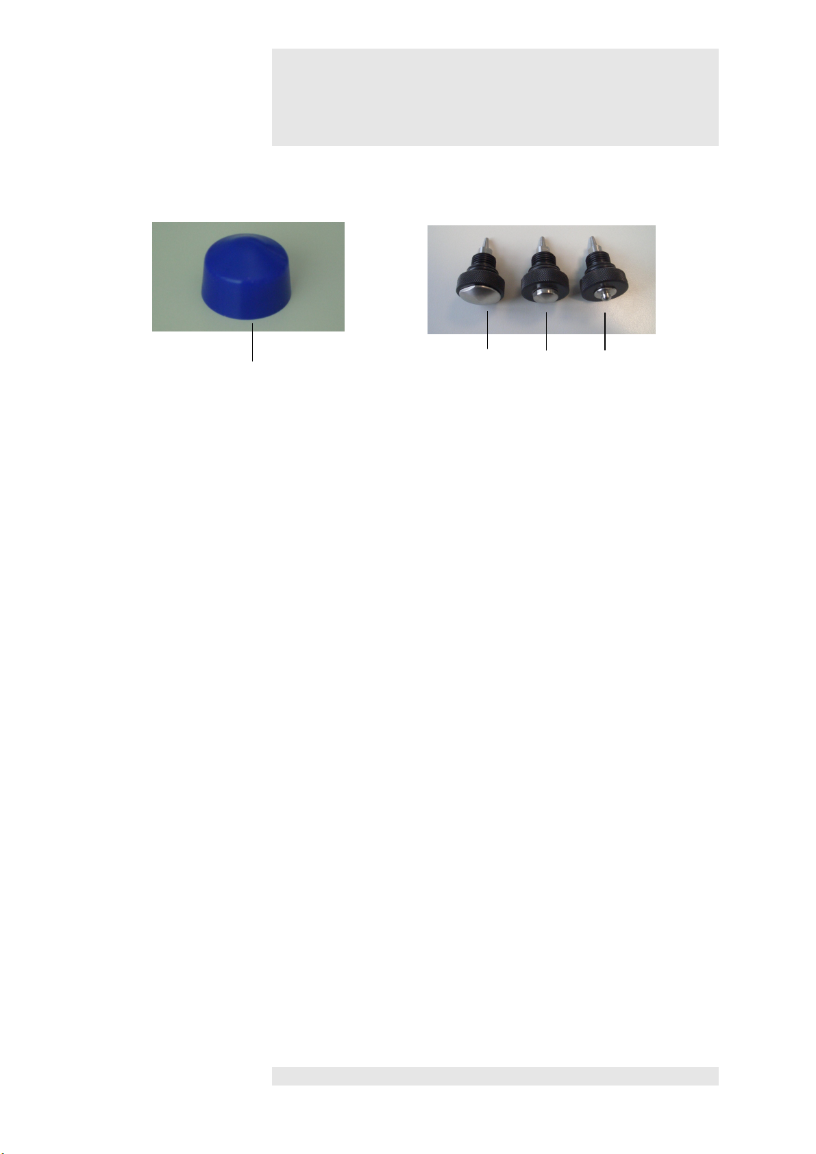
21 Silicone cap
Accessories
21 22 23 24
22 25 mm applicator head
23 15 mm applicator head
24 6 mm applicator head
Page 6

Contents
5
en
Puls
Front view of device
Rear view of device
Accessories
Figures
Figures - Control unit / Handpiece / Footswitch
Figures - Display
Figures – Switch and connector sockets
enPuls briefly
1
1.1. Summary
1.2. Quick operation instruction
1.3. How to use enPuls
1.4. Handpiece
1.5. Applicator heads
1.6. Footswitch
7
8
10
11
12
13
Installation
2
3
4
5
6
7
2.1. Fitting the cables, starting the system
2.2. Settings
SD-Card 17
Treatment screen 18
Favorites and Memory list
5.1. Saving modified programmes
5.2. Retrieving and editing Favorites list and the
Memory list
Description of the selection keys 24
Medical information
7.1. Indications
7.2. Contraindications
14
15
21
22
26
27
Page 7

Contents
6
Valid for the en
Puls V.2.0 devices
General Information
8
8.1. Explanation of symbols
8.2. Warnings
8.3. Technical data
8.4. Technical information
8.5. CE Marking / Legal information
28
29
30
31
32
9
10
11
12
13
14
Maintenance 33
Troubleshooting 35
Function test 37
Error messages 38
Scope of delivery - Accessories 39
Manufacturer’s declaration of Electromagnetic
Compatibility
These operating instructions are an integral part of the device.
They must be stored with the device and kept accessible at all times for anyone authorized to
operate this device. These Instructions form is a part of the appartures and must be kept with it
at all times. Full observation of these instructions is a requirement for the correct application
and operation of the equipment and for consequent saftey for patient and operator.
These operating instructions are valid from 01 June 2011.
40
Page 8

en
Puls
briefly
7
What is en
Puls
? A state of the art therapeutic massager
Radial Pulse Therapy
Radial
Pulse Therapy
is a procedure for relief of minor muscl
e aches and
What does
Creation of
radial pulses
using an ergonomic handpiece and the
How are radial
An electromagnetic field is generated via a coil in the back of the
What are the
The innovative technology allows a compact design with no need for a
The unit must only be operated by medical practitionars.
enPuls do?
pulses generated
with enPuls?
1.1. Summary
pains and for temporary increase in local blood circulation
transmittal of the radial pulses via special applicators.
enPuls has a maximum penetration depth of about 35 mm in human
tissue.
handpiece.
A projectile is accelerated as a result of the field; this strikes against the
applicator head at the front of the handpiece and generates pulses,
which spread out radially in the tissue.
1
advantages
of enPuls?
Note:
!
Caution
compressor.
The clear and modern colour display shows all relevant parameters for
treatment and the modern touch operation ensures pleasure and
motivation when providing treatment.
Individual program start configuration and clear, simple menu navigation
make operation of the device easy and comfortable for users.
Infinitely variable frequencies and various applicators allow treatment to
be adapted to the particular condition of the patient.
The compact design saves room in the practice and is highly suited for
use in home visits.
enPuls has been constructed and designed solely for the treatment of
superficial orthopaedic problems in humans and animals.
Federal law restricts this device to sale by or on the order of a physician.
Page 9
en
Puls
briefly
8
Note:
The following d
escriptions are all based on
factory settings.
Note:
All buttons, menus and submenus are activated direct
ly on the screen by
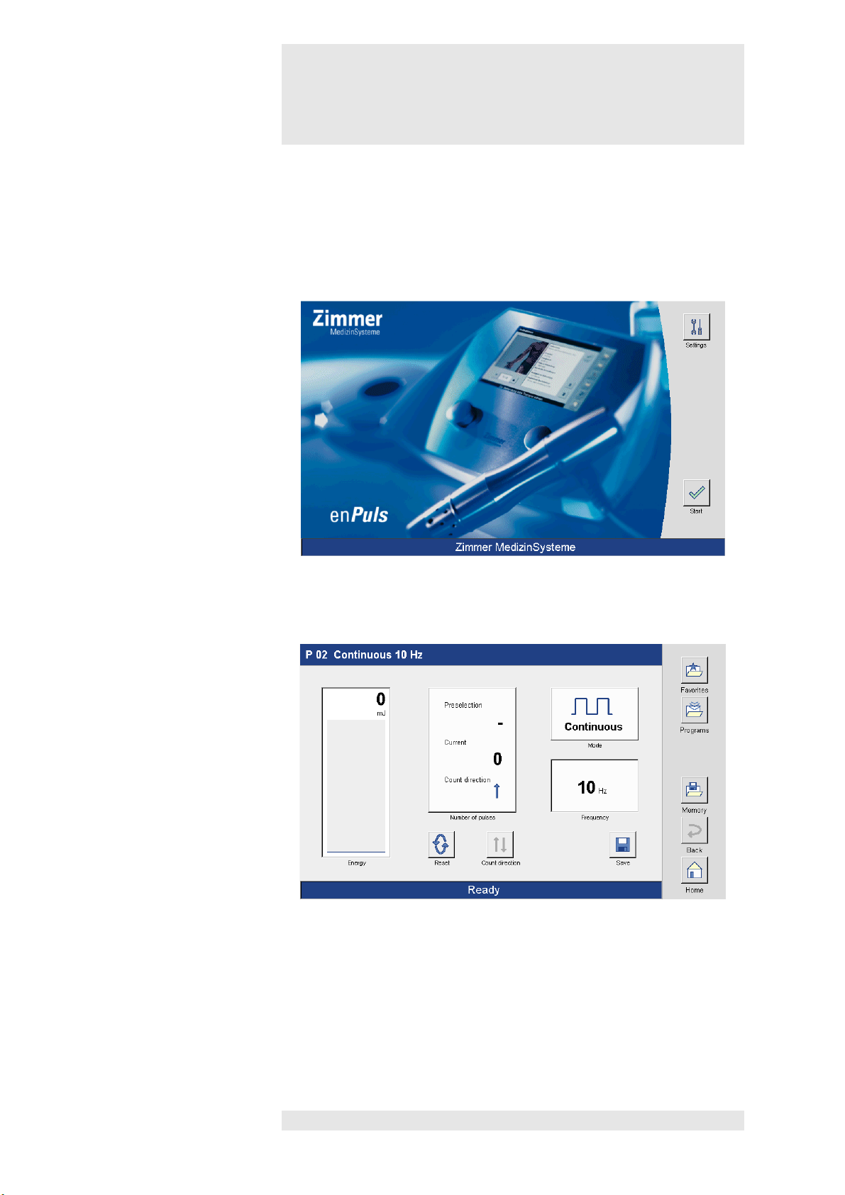
Starting the program
Treatment screen
1.2. Quick operation instruction
touching or using the touch pen.
1
Applicator
Positioning handpiece /
applicator
Press the “Start” button to open the treatment screen for program
P 02.
Select the appropriate applicator head for the treatment you wish to carry
out and screw this correctly onto the handpiece.
Position the handpiece on the selected treatment point / field. To avoid
any friction on the skin, enPuls lotion may first be applied onto the
treatment area.
Page 10

en
Puls
briefly
9
When using lubricants,
the applicator head must be covered with a
Setting the frequency
Adjust the frequency using the right controller, if necessary.
Setting
Adjust the pulse
energy using the left controller.
Start
ing treatment
Depress the footswitch to start the treatment.
Note:
Only activate the
unit via the footswitch once the handpiece has been
Ending treatme
nt Deactivating the footswitch interrupts or ends the treatment. The display
Note:
During tr
eatment, the patient must be observed closely and the treatment
!
Caution
the pulse energy
1.2. Quick operation instruction
silicone cap to protect it.
The display in the bottom status bar changes from ‘Ready’ to ‘Active’.
1
positioned on the patient.
in the bottom status bar changes from ‘Active’ to ‘Ready’.
The device ends the treatment automatically once the preselected
number of pulses has been reached.
must be adjusted, if necessary, or discontinued, should any problems
arise.
Page 11

en
Puls
briefly
10
Start treatment
enPuls operates with mechanical energy.
When using en
Puls lotion or other lubrica
nts, the applicator head must
Note:
Despite high internal damping as a result of the weight and design of the
Note:
The patient should be carefully monitored throughout the treatment.
1.3. How to use enPuls
The energy is transmitted to the patient via a handpiece, which is usually
held in one hand.
To do this, the handpiece is placed on the area or point of treatment with
the applicator head held vertically.
When the unit is activated, it is possible to work either steadily on a
single site or dynamically over an area.
It is advisable to use enPuls lotion (included in the accessories) in order
to reduce friction on the skin.
The weight of the handpiece means that it is normally not necessary to
apply pressure to the treatment area / point.
The handpiece is placed on the treatment area / point and held loosely in
position with one hand.
If required, additional pressure may be applied in the direction of the
tissue, and the working angle can be varied.
1
!
Caution
be covered with a silicone cap to protect it.
handpiece, vibrations may cause strain to the user's hand.
Recommended protective measure:
- Limit the duration of exposure
Page 12

en
Puls
briefly
11
The handpiece (7) contains the
pulse
generator, a fan to dissipate heat
Note:
The
pulse
generator in the handpiece is an expendable part and has to be
Zimmer MedizinSystems
guarantees unrestricted use of at lea
st 2 million
To work with the handpiece on a patient, it is essential that one of the
The cable should not be stretched beyond its maximum length and must
Standby m
ode on device
The fan in the handpiece is started by depressing the footswitch and stops
1.4. Handpiece
and the slot for the different applicator heads. It is connected to the control
unit (1).
replaced after a specific period of use, as its functionality decreases over
time.
pulses per pulse generator.
Wear on the pulse generator varies. Depending on performance and
frequency, sometimes far more than 2 million pulses can be delivered.
For more information on the need to replace the pulse generator, see
chapter 10.
1
and handpiece
applicator heads is screwed tightly onto the handpiece as far as it will go.
be protected against pinching or any other mechanical damage.
To avoid heat accumulating in the handpiece, it is essential to ensure that
the hand holding it or anything else does not block the air vents at the top,
and particularly, on the base of the handpiece.
automatically after reaching a certain temperature.
Page 13
en
Puls
briefly
12
There are 3 different applicator heads available for treatment.
Changing
To change the various applicator heads, hold the handpiece in one hand
Note:
Applicator heads are expendable parts and must be replaced after a
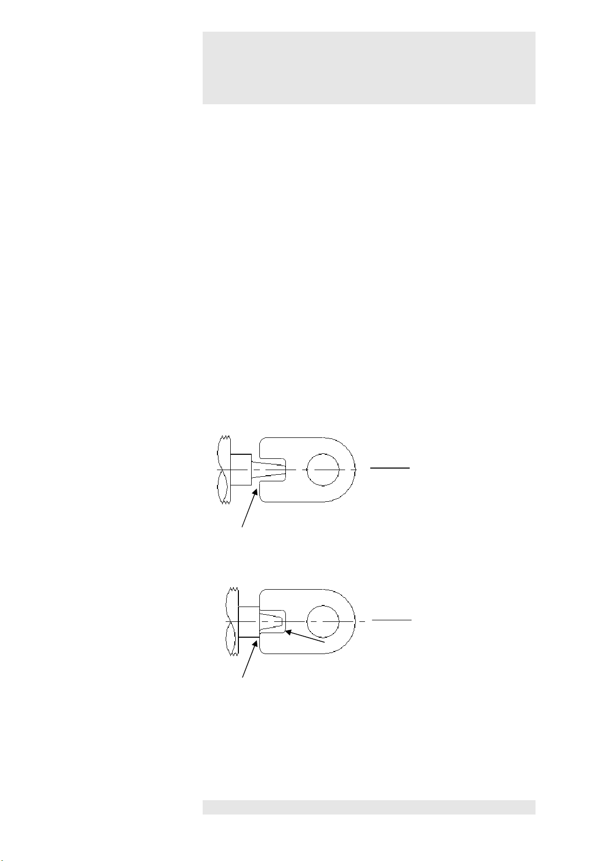
Minor / slight deformation or shortening of the rear impact dom
e does not
Air gap
applicator OK
Test template
Test template
applicator heads
1.5. Applicator heads
and unscrew the applicator head from the handpiece with the other hand
(anticlockwise). Screw the required head tightly onto the handpiece
(clockwise), until the black outside ring of the applicator head rests on the
handpiece (there should no longer be any thread visible).
certain period of use.
affect functionality.
In cases of greater deformation or stronger shortening of the rear impact
dome the applicator head must be replaced.
A test template is supplied with the device that enables the user to test if
the wear limit has been reached
(see diagram).
1
Template makes contact or air gap at the tip Wear limit has been reached
Page 14

en
Puls
briefly
13
Place the footswitch so that it can be reached easily during treatment.
1.6. Footswitch
The footswitch control unit is multi-directional so it is not necessary to
align the footswitch exactly.
To avoid damage, please note that only slight pressure needs to be
exerted on the switch. Use the front part of your foot, not the heel to
operate the footswitch.
The switch does not have a locking device, which means that it only
remains actuated as long as pressure is applied to it.
1
Page 15

Installation
14
Note:
Before starting up the system, remove enPuls from its transport case.
Note:
Make sure that the main switch on the device is
set to '0'.
Connecting the
Connect the mains cable to the designated port (17) of the device and
Connecting
Plug the handpiece into the appropriate socket (1
8
) of the device and
Note:
Ensure that an applicator head is inserted into the handpiece and that it
Connecting
Plug the footswitch into the appropriate socket (1
9
) of the device and
Switching on the device
Switch on the device using the main switch (15).
mains cable
the handpiece
2.1. Fitting the cables, starting the
2
system
Do not operate the device while it is in the case.
Ensure that enPuls is placed on a stable surface.
then plug into the mains.
place it on the table.
is properly screwed in as far as it will go.
the footswitch
then place it on the floor.
Page 16

Inst
allation
15
Note:
Changes to the default settings can only be made from the start screen.
Language
Press this button to open the menu to select the language. The language
Start settings
Start screen
Option to choose between 5 start screens.
Start display
Option to choose between 2 start displays:
Welcome message
Option to configure an individual welcome message.
2.2. Settings
Press button “Settings” to open the Settings screen
2
Figure 1
is selected by pressing on the appropriate row in the pull down menu.
Press the button to open the pull down menu to select the start screen.
The start screen is selected by pressing on the appropriate row.
Press the button to open the menu to select the start display.
The start display is selected by pressing on the appropriate row.
Activate the welcome message field to open the keyboard in order to
enter a welcome message.
Page 17

Inst
allation
16
Audio / graphic settings
Brightness
Option to adjust the brightness of the screen lighting.
Handpiece
The count
er status for the handpiece that is currently connected, is
Version
Press the version button to open the window with information about the
Default
Press the default bu
tton to reset the factory default settings.
Touch calibration
Press the “Touch Calibration” button to open the screen to carry out the
Alternative language
The o
ption “Alternative language” is inactive.
Volume
counter status
2.2. Settings
Adjust the volume using the two arrow keys.
Option to adjust the volume of the signals when activating the control
fields.
shown in this display field.
current software version of the device.
2
settings
touch calibration.
This can be done to improve the touch input if it is not sufficiently
accurate.
First press the + symbol in the top left corner. A + symbol appears then
in the lower right corner.
Then precisely press the + symbol in the lower right corner.
Repeat the procedure to complete the touch calibration.
Page 18

SD
-
Card
17
User
-
defined settings are saved on the SD card.
Note:
If the SD card is not inserted, the message ‘SD card not found’ appears
3
when the 'Favorites' and 'Memory' buttons are pressed.
Deactivate the message by pressing the button “OK” and continue.
Page 19

Treatment screen
18
Title bar
The title bar shows t
he name of the current program
.
Status bar
The status bar shows the information about the current status of the
Mode
Shows the selected operational mode (continuous in this case).
Frequency
Shows the selected frequency.
4
treatment. If the treatment is not active, it shows the word ‘Ready' and if
treatment is running the text 'Active' appears.
Press the 'Mode' button to open the 'Input' window and select the
operational mode (continuous, Burst 4 Pulses, Burst 8 Pulses, Burst 12
Pulses)
Change the frequency using the right controller.
Frequency range: 1 Hz – 16 Hz, adjustable using the right controller in
1 Hz steps.
Page 20

Treatment screen
19
Energy/ Bar graph
Shows the selec
ted pulse
energy. When treatment is active the bar
Save
After changing the parameters, bas
ed on individual needs, press the
Count direction
Press to set the count direction (increasing or decreasing) of the number
Number of
pulses
Shows the pre
-
selected
pulse
numbers as well as the current number of
Note:
enPuls offers two options for
pulse
delivery:
4
graph is filled in.
Setting the pulse energy can be done either before or during pulse
delivery.
The pulse energy can be set at the levels 60, 90, 120 or 185 mJ.
button “Save” for saving the settings either in the Favourites list or the
Memory list.
of pulses set.
Pulse delivery without
pre-selecting the pulse
number
pulses delivered to the patient.
Also the count direction (increasing in this case) is shown.
Pressing the “Number of pulses” field opens the Input window, defining
pre-selection.
For pulse delivery with no pre-selected number of pulses, the device
does not end the treatment. As long as the footswitch is activated, pulses
will be delivered.
For pulse delivery with no pre-selected number of pulses, only the
upward count direction is active.
Page 21

Treatment screen
20
Pulse
delivery with
For
pulse
delivery with a pre
-
selected
pu
lse number, the device ends the
When the number of
pulses
is pre
-
selected the count direction is
4
pre-selection of the
number of pulses
treatment once the pre-selected number of pulses has been reached.
The footswitch is deactivated and pulse delivery is no longer possible.
The treatment can be continued by resetting the current number of
pulses or by adjusting the pre-selection.
automatically set to decreasing. By pressing the 'Count direction' button
on the treatment screen the increasing count direction button can be
selected.
Page 22

Favo
rites and Memory list
21
Prog
ram
s c
an be stored either in the Favo
rites
list or the Memory list.
Program
name
For saving the program enter the program
name using the keyboard
Favo
rites
Press the “Favo
rites” button to open the Favourites list and automatica
lly
Memory
Press the “Memory” button to open the Memory list and
automatically
No
te:
If the 'Memory' or ‘Favo
rites’ button is pres
sed without entering a
5.1. Saving modified program
5
save the program.
The program is automatically saved in the first free space in the list.
save the program.
The program is automatically saved in the first free space in the list.
program name, an error message appears.
Acknowledge these message with ‘OK’, enter a program name and
repeat the save procedure as described above.
Page 23

Favo
rites and Memory list
22
Note
The following steps to
edit the Favourites list correspond exactly to those
Individual saved programs are listed in Favo
rites or Memory list.
Selecting th
e Memory or
In the navigation bar press the ‘Favourites’ or ‘Memory’ button to open
Retrieving a
In the l
ist select the desired program
by pressing the appropriate row.
Favorites list
5.2. Retrieving and editing Favorites
list and the Memory list
used to edit the Memory list.
From here they can be:
1. retrieved for treatment or
2. edited (sequence changed or deleted).
the corresponding list.
5
program
Page 24

Favo
rites and Memory list
23
Editing
Press the
‘Edit’
button to open the 'Edit Favo
rites' screen
Activate the desired program
by pressing the appropriate row.
You are now able to
5.2. Retrieving and editing Favorites
5
list and the Memory list
• Move or
• Delete
the selected program.
Page 25

Description of the
selection keys
24
Press the button to ope
n the screen to save
a program
.
Can be used to reverse the counting direction.
Pressing the key reset the current number of
pulses
Press the button to move an item of the list upwards by one position.
Press the button to move an item of the list downwards by one position.
Press the button
to delete the selected program
from the list.
Scrolling forwards
Scrolling backwards
The changes are applied by pressing the button.
The “Save” button can only be pressed from the treatment screen.
• to 0 by increasing counting direction
• to the preset value by decreasing counting direction.
6
Press the button to scroll one page down the list.
Press the button to scroll one page up the list.
Page 26

Description of the
selection keys
25
Press the button to reject the changes made.
Activation of the „+“ button increase the pulse rate in 1000 increments,
Press t
he but
ton to open the Program
window
.
Press the button to return to the Start screen.
activation of the „-“ button reduces the number of the pulses in 1000
steps.
Activation of the „+“ button increase the pulse rate in 100 increments,
activation of the „-“ button reduces the number of the pulses in 100 steps.
6
Page 27

Medical information
26
•
7.1. Indications
For relief of minor muscle aches and pains and for temporary
increase in local blood circulation
7
Page 28

Medical information
27
•
7.2. Contraindications
vascular diseases present in or near the treatment area
• local infections in the treatment area
• around malignant or benign tumours
• directly on cartilage surfaces or near the small facet joints of the
spinal column
• directly over implanted electronic devices such as pacemakers,
analgesic pumps, etc.
• in areas, in which mechanical energy in the form of vibrations may
lead to tissue damage such as metal implants after a fracture
In general we advise against treatments
• if blood clotting disorders are present or the patient is receiving
treatment that results in a change in the blood clotting behaviour
• during pregnancy
• on patients with neurological diseases resulting in impairment of the
vasomotor function in the treatment area
• over air-filled cavities such as treatment on the thoracic spine, etc.
• on children, particularly around the epiphyseal plates
Care is required for patients
• with impaired sensibility
• with severe autonomic disorders
• under the influence of drugs and/or alcohol
as circulatory stresses and inadequate treatment responses cannot be
excluded.
7
Page 29

General information
8.1. Explanation of symbols
28
Danger / Warning
In the Operating Instructions, this symbol stands for
Danger / Warning
.
Caution
In the Operating Instructions this symbol stands for '
Caution
' with regard
Instrument type BF (according
IEC
60601
-
1):
Value of the accessible fuses
to possible damage to property.
!
Port for handpiece
8
Port for footswitch
Follow Operating Instructions
Degree of protection against electric shock
Device must not be used at heart
Class II
ETL Testmark
Page 30

General information
8.2. Warnings
29
Users of the en
Puls device must be trained in how to use the system
properly and have the appropriate skills.
Any treatment instructions regarding treatment location, duration and
strength require medical knowledge and should only be given by
authorized doctors, therapists and health paraprofessionals. It is
imperative that these instructions are followed.
Treatment must always be carried out under medical supervision.
The enPuls handpiece is not designed for permanent use. After a
treatment with max. 6000 pulses, a break of 15 min. becomes
necessary.
The instruments must only be operated with the mains cable
provided. Protect the mains cable from any mechanical stress.
Warning:
Patients who are concurrently receiving treatment involving a
reduction and/or modification of blood clotting or prolongation of the
blood clotting time (e.g. with acetylsalicylic acid) should consult their
therapist about possibly stopping this treatment as these patients
may be more prone to greater haemorrhaging and bruising when
radial pulses are applied.
Radial Pulses are strongly scattered in air pockets and create
reflections that may have negative effects.
You must therefore never perform any direct treatments over the
lungs (intercostal spaces) or the gastrointestinal area.
It must not be used in wet areas. If it is used in wet areas, significant
damage may result, and patients and users may be endangered.
Warning:
This device should not be used over swollen or inflamed areas or
skin eruptions. Do not use in presence of unexplained calf pain.
Consult a physician.
8
Page 31

General information
8.3. Technical data
30
Intended use:
Therapeutic massager
Dimensions
L 322 mm / W 235 mm / H 130 mm
Weight
2.7 kg
Power supply
100–240 VAC / 50/60 Hz
Fuse
3,15 AT
Protection class
ll
Application class
BF
Frequency range
1 Hz
– 16 Hz, can be adjusted in 1 Hz steps
3 burst modes
4, 8, 12
pulses
with 16 Hz (0.5 s)
Pulse
energy levels
4 selectable fixed settings
60 / 90 / 120 / 185 mJ (at the applicator)
Mode of operation
Intermittent use max. 6000
pulses
/ 15min. break
Accuracy
±
20%
H
andpiece:
Ergonomic model with anodized aluminium case and fan cooling
Dimensions
230 mm in length, 50 mm diameter
Weight
850 g (with cable)
Service life
2,000,000
Pulses
(minimum)
Applicator heads exchangeable without any tools (6 / 15 / 25 mm
Dimensions
L 580 mm / W 470 mm / H 250 mm
Total weight
13 kg (total with case)
Environmental conditions
Oper
ational environment
10 to 35 °C (50 to 75 °F); 700 hPa
– 1060 hPa
20% to 80% rel. humidity, not condensed
Storage / Transport
Short
-
term -
10 to 55 °C (14 to 131 °F); 700 hPa
– 1060 hPa
Long
-
term 0 to 40 °C
(32 to 104 °F); 700 hPa
– 1060 hPa
Regulatory Compliance
IEC/EN 60601
-1
at 16 Hz max. 120 mJ
8
(complete with case)
diameter)
20% to 80% rel. humidity, not condensed
20% to 80% rel. humidity, not condensed
IEC/EN 60601-1-2
Page 32

General information
8.4. Technical information
31
As the manufacturer Zimmer MedizinSystem
s can only be responsible
for the safety and reliability under the following circumstances:
• if the device is operated from an approved, grounded wall socket
• if the device is operated in accordance with the Operating
Instructions
• if extensions, reconfigurations or modifications are implemented only
by persons authorized by Zimmer MedizinSystems
• users must ensure that the device and the handpiece are operating
correctly; are mechanically intact and are in good condition before
using them
• disconnect the device from the power supply immediately if it is
exposed to liquids.
The device does not contain any parts that must be maintained or
repaired by the operator.
8
Page 33

General information
8.5. Legal information
32
Legal Information
National laws and regulations must be observed when installing and
operating this treatment device.
8
Page 34

Maintenance
33
Separate servicing is not required for thi
s product.
Before starting any maintenance or cleaning, the device must always be
When usin
g lubricants, it is essential to pull the silicone cap over the
Note:
In this c
ase the warranty becomes void.
Cleaning / disinfection
Clean the device and handpiece with soap lotions or cleaning agents that
N
ote: It is essential to ensure that no moisture gets into the system when
!
Attention !
9
switched off at the main switch and the plug pulled out.
You should also check the applicators domes for any wear, as described
in chapter 1.5.
applicator head.
If you do not use the protective cap, the lubricant can get inside the
applicator head and handpiece, which can lead to permanent soiling and
malfunctioning.
do not content alcohol or solvents.
Conventional disinfecting products used for medical equipment are
suitable.
cleaning.
Page 35

Maintenance
9
34
Monitoring the
Generating mechanical
radial pulse
energy causes a considerable build
handpiece
temperature
up of heat in the handpiece. To avoid shortening the lifetime of the
handpiece, a temperature switch has been integrated. This triggers an
internal switch-off, if the temperature becomes too high, forcing the
handpiece to cool.
If the temperature switch is activated, this is indicated by a message on
the display and pulses can no longer be emitted.
After acknowledging the message with ‘OK’, the treatment screen comes
to the foreground with the message 'Over temperature' in the status bar.
As soon as the handpiece has reached the operating temperature, the
message 'Over temperature' is replaced by the message 'Ready' in the
status bar and the treatment can be continued.
Page 36

Troubleshooting
10
35
Failure or malfunction
Check to ensure that the handpiece plug is properly connected to the
Irregular delivery
Possible cause 1:
Wear of applicator head
Remedying
Removal of parts subject to abrasion:
Possible cause 2: Wear of
pulse
generator
Remedying
If the total number of 2 million
pulses
has been reached or
exceeded, the
of the handpiece
of radial pulses /
overheating
of handpiece
cause 1
device.
It must be fully engaged.
Check the cable of the handpiece for any mechanical damage.
Difficult to move due to wear
Applicator heads are wear parts and should be replaced after a specific
number of pulses.
Remove the applicator head from the handpiece and clean the rear
dome thoroughly. Then hold the handpiece, without the applicator head,
with the opening downward and, at 2 or 5 Hz frequency, release a few
pulses (maximum 10) at the lowest energy level. Then reinsert the
applicator head.
If the error still occurs, the applicator head has to be changed.
cause 2
The pulse generator is an expendable part and should be replaced after
2 million pulses.
Check the total number of pulses of the device in the configuration menu.
pulse generator must be replaced.
To replace the pulse generator, contact a qualified customer engineer or
the head office in Irvine, USA.
Page 37

Troubleshooting
10
36
No response at
Make sure that the mains plug is properly ins
erted in the power outlet
Only replace a fuse with one of exactly the same name or one that is
main switch /
display remains
dark
and the device connector is firmly plugged into the device port.
Inspect the mains cable for damage.
Check the power supply and the power plug.
Above the mains input socket of the device, there are fine-wire fuses,
which isolate the mains voltage in the event of any electrical problem.
Open the flap and check the fuses.
Replace any faulty fuses.
equivalent. Before doing this, check the entire power supply for any
possible faults.
If the error occurs again, it is essential to inform the service/after-sales
service department.
Page 38

Function test
11
37
enPuls
runs a self
-
test that checks all internal components after it is
In addition, a function test shall be made as follows.
This test shall be made monthly or in case of doubt about the proper
Note:
Before performing the function test, check whether the handpiece and
Function test
Testing
Switch on the device.
Note:
On conclusion of the test, switch off the device at the main switch.
switched on.
An error message is shown in case of faults.
function of the device.
the footswitch are connected correctly to the device.
Check for proper mains connection.
Depress the footswitch briefly – the fan and pulse generator will start
immediately, whereby the pulse generator has to operate at the
frequency indicated on the display (5 Hz as default value).
If a treatment is to be performed immediately afterwards, set the required
treatment parameters and proceed as mentioned in Chapter 4.
Page 39

Error Messages
38
In the status bar the
Check that the handpiece is correctly connected
Monitoring
Generating mechanical
pulse
energy causes a considerable build up of
In the status bar the
Check that the
pulse
energy is set.
No SD
-
Card found
If the SD card is not inserted, the message ‘SD card not found’ appears
Disposal
The device must be disposed of by an approved disposal company and
message 'Handpiece not
found' appears.
12
the handpiece
temperature
message 'Ready' appears
and despite depressing
the footswitch no pulse
is triggered.
heat in the handpiece. To avoid shortening the lifetime of the handpiece,
a temperature switch has been integrated. This triggers an internal
switch-off, if the temperature becomes too high, forcing the handpiece to
cool.
If the temperature switch is activated, this is indicated by a message on
the display and pulses can no longer be emitted.
After acknowledging the message with ‘OK’, the treatment screen comes
to the foreground with the message 'Over temperature' in the status bar.
As soon as the handpiece has reached the operating temperature, the
message 'Over temperature' is replaced by the message 'Ready' in the
status bar and the treatment can be continued.
Check that the footswitch is correctly connected.
Inspect the footswitch cable for any damage or kinks.
Check whether the footswitch dome can be moved or whether it is
blocked.
Please contact after-sales service if this fails.
After-sales service is reached through your authorised sales
representative or by contacting the head office in Irvine, USA.
when the 'Favourites' and 'Memory' buttons are pressed.
Insert card and confirm with ‘OK’.
must not be discarded with household or special waste.
Page 40

Scope of delivery, Acce
ssories
13
39
Scope of delivery
5416
1
Control
unit en
Puls Version 2.0
5410
1
Handpiece, complete with a 15 mm applicator head
93133521
1
6 mm applicator head
93133511
1
15 mm applicator head
93133501
1
25 mm applicator head
50500017
10
Silicone caps
50500018
1 enPuls lotion
94130410
1
Footswitc
h
67300128
1
Mains cable
10101
888 1 Operating instructions
63061010
1
Test template
87053010
1
Transport case
65800410
2
Touch pens
63230311
1
Holder for handpiece
Accessories
Item No.
63230311
Holder for handpiece
93133521
6 mm applicato
r head
93133511
15 mm applicator head
93133501
25 mm applicator head
50500017
Silicone cap
50500018
enPuls lotion
94130410
Footswitch
67300128
Mains cable
87053010
Transport case with foam insert
10101
888 Operating Instructions
63061010
Test tem
plate
65800410
Touch pen
Page 41

Manufacturer’s declaration of
Electromagnetic Compatibility
40
Guidelines and manufacturer's declaration
– electromagnetic interference
The device en
Puls Versio
n 2.0 is intended for operation in an electromagnetic environment as indicated below.
The
Interference tests
Conformity
Electromagnetic environment guide
line
RF emissions according to CISPR 11
Group 1
The device en
Puls Version 2.0 uses RF
RF emissions according to CISPR 11
Class A
The device en
Puls Version 2.0 is suitable for
Harmonic emissions according to IEC
Class A
Voltage fluctuation emissions and flicker
Conforms
14
Medical electrical devices such as enPuls Version 2.0 are subject to special precautions with regard to electromagnetic
compatibility (EMC) and must be installed and commissioned in accordance with the EMC advice given in the instructions for
use and accompanying documents.
Portable and mobile RF communication systems (e.g. mobile phones) may interfere with medical electrical equipment.
enPuls Version 2.0 should only be operated with the original mains cable specified in the list of contents delivered.
Operating the device with any other mains cable can lead to increased emissions or reduced interference immunity of the
device.
customer or user of the enPuls Version 2.0 should ensure that it is operated in such an environment.
energy solely for its internal functioning. Its RF
emission is therefore very low and it is unlikely
that this will cause interference to
neighbouring electronic equipment.
use in all installations including those in a
61000-3-2
according to IEC 61000-3-3
The device should not be used when placed immediately next to or stacked on top of other devices. If operation is necessary
when immediately next to or stacked on top of other devices, the device should be monitored to ensure it is operating as
intended in this arrangement.
residential environment and those which are
directly connected to the public mains network
which also supplies buildings which are used
for residential purposes.
Page 42

Manufacturer’s declaration of
Electromagnetic Compatibility
41
Guidance and manufacturer’s declaration
– Elec
tromagnetic immunity
The en
Puls Version 2.0 device is intended for use in the electromagnetic environment specified below. The customer or the
Immunity test
IEC 6
0601 test level
Compliance level
Electromagnetic environment
-
Electrostatic discharge
± 6 kV contact
± 6 kV contact
Floors should be wood, concrete or
Electrical fast transient /
± 2 kV for power
± 2 kV for power supply
Mains power quality should be that
of a
Surge IEC 6100
-4-5
± 1 kV differential
± 1 kV differential mode
Mains power quality should be that of a
Voltage dip
s, short
<5% U
<5% U
Mains power quality should be that of a
Power frequency
3 A/m
3 A/m
Power frequ
ency magnetic fields should
Note: U
is the AC mains voltage prior to application of the test level.
user of the enPuls Version 2.0 device should assure that it is used in such an environment.
Guidance
14
(ESD) to IEC 61000-4-2
burst to IEC 61000-4-4
interruptions and voltage
variations on power supply
input lines IEC 61000-4-11
± 8 kV air
supply lines
± 1 kV for input /
output lines
mode
± 2 kV common mode
T
(>95% dip in UT for
0.5 cycle)
40% UT
(60% dip in UT for 5
cycles)
70% UT
(30% dip in UT for 25
cycles)
<5% UT
(>95% dip in UT for 5
seconds)
± 8 kV air
lines
not applicable
± 2 kV common mode
T
(>95% dip in UT for 0.5
cycle)
40% UT
(60% dip in UT for 5
cycles)
70% UT
(30% dip in UT for 25
cycles)
<5% UT
(>95% dip in UT for 5
seconds)
ceramic tile. If floors are covered with
synthetic material, the relative humidity
should be at least 30%.
typical commercial or hospital
environment.
typical commercial or hospital
environment.
typical commercial or hospital
environment. The user of the enPuls
Version 2.0 requires continued operation
during power mains interruptions. It is
recommended that the enPuls Version
2.0 be powered from an uninterruptable
power supply or a battery.
(50/60 Hz) magnetic field
to IEC 61000-4-8
T
be at levels characteristic of a typical
location in a typical commerical or
hospital environment.
Page 43

Manufacturer’s declaration of
Electromagnetic Compatibility
42
Guidelines and manufacturer's declaration
– electromagnetic interference immunity
The device en
Puls
Version 2.0 is intended for operation in the electromagnetic environment specified below.
The customer
Interference
IEC 60601
-
test level
Compliance l
evel Electromagnetic environment
- guidelines
Conducted RF
3 V
3 V
Portable and mobile radio equipment should
NOTE 1 At 80 MHz and 800 MHz the higher frequency range is applicable
.
14
The main features of the enPuls Version 2.0 are as follows: interference-free delivery of pulses, interference-free control of
all functions. Uninterrupted operation is not required with the use intended.
or user of the enPuls Version 2.0 should ensure that it is used in such an environment.
immunity tests
disturbance variables
according to IEC
61000-4-6
Radiated RF
disturbance variables
according to IEC
61000-4-3
effektive value
150 kHz to 80 MHz
3 V/m
80 MHz to 2.5 GHz
effektive value
150 kHz to 80 MHz
3 V/m
80 MHz to 2.5 GHz
not be used any closer to the enPuls Version
2.0, including cables, than the recommended
separation distance calculated from the
equation applicable to the transmission
frequency.
Recommended separation distance:
d= 1.2 √P
d= 0.35 √P for 80 MHz to 800 MHz
d= 0,7 √P for 800 MHz to 2.5 GHz
Where P is the rated power of the transmitter
in Watts (W) according to the transmitter
manufacturer and d is the recommended
separation distance in meters (m).
According to an investigation in situa, the field
strength of stationary radio transmitters should
be less than the compliance level at all
frequencies.
Interference may occur in the vicinity of
equipment which is marked with the following
symbol:
NOTE 2 These guidelines may not be applicable in all cases. Electromagnetic propagation is affected by absorption and
reflection from structures, objects and people.
Page 44

Manufacturer’s declaration of
Electromagnetic Compatibility
43
Theoretically, it is not possible to exactly predict the field strengths of fixed transmitters such as base stations for
Recommended separation distances between portable and mobile RF telecommunications equipment and the
The en
Puls Version 2.0 device is intended f
or operation in an electromagnetic environment where RF disturbances are
Rated output of transmitter
Separation distance according to frequency of transmitter
150 kH
z to 80 MHz
80 MHz to 800 MHz
800 MHz to 2.5 GHz
0.01 0.12 0.035 0.07
0.1 0.38 0.11 0.22
1 1.2 0.35 0.70
10 3.8 1.1 2.2
100 12 3.5 7
For transmitters rated at a maximum output which is not listed above, the recommended
separation distance d in
meters
(m) can be
14
a
radio telephones and land mobile radios, amateur radio stations, AM and FM radio and TV broadcasting. To determine the
electromagnetic environment in relation to the fixed transmitters, an electromagnetic site survey should be considered. If the
measured field strength in the location where the enPuls Version 2.0 device is to be used exceeds the above compliance
levels, the enPuls Version 2.0 device should be monitored in order to ensure that it is functioning as intended. If unusual
features are noticed, additional measures may be necessary such as re-orienting or relocating the enPuls Version 2.0
device.
b
Above the frequency range from 150 kHz to 80 MHz the field strength should be less than 3 V/m.
enPuls Version 2.0 device
monitored. The customer or user of the enPuls Version 2.0 device can help prevent electromagnetic interference by
maintaining a minimum distance between portable and mobile RF telecommunications equipment (transmitters) and the
enPuls Version 2.0 device – according to the output power of the communications device, as indicated below.
W
d= 1.2 √P
determined using the equation applicable to the respective column, whereby P is the maximum rated output of the transmitter in Watts (W)
according to the transmitter manufacturer.
NOTE 1 At 80 MHz and 800 MHz the higher frequency range is applicable.
NOTE 2 These guidelines may not be applicable in all cases. Electromagnetic propagation is affected by absorption and reflection from
structures, objects and people.
d= 0.35 √P
m
d= 0.7 √P
Page 45

enPuls
Version 2.0
User Manual
USA 10 101 888 UR 0212 I Modifications reserved
Zimmer MedizinSystems
25 Mauchly, Suite 300
Irvine, CA. 92618
800 327 3576
949 727 2154 fax
www.zimmerusa.com
info@zimmerusa.com
 Loading...