

Page 1
A.T.S. 3000 AUTOMATIC TOURNIQUET SYSTEM
Operator
& Service Manual
Zimmer A.T.S.® 3000
AUTOMATIC TOURNIQUET SYSTEM
REF 60-3000-101-00
Page 2

A.T.S. 3000 AUTOMATIC TOURNIQUET SYSTEM
LIMITED ONE YEAR WARRANTY (U.S.A.)
SCOPE OF LIMITED WARRANTY
Zimmer, Inc. warrants the Product (A.T.S. 3000 Tourniquet System) for one year from date of purchase. During the warranty
period, Zimmer will repair or replace, at its option, any product which is defective in materials or workmanship or which fails to
meet the published specification for that model. This Limited Warranty is made only to the original purchaser of the product and
is non-transferable. The remedies described in this Limited Warranty are the exclusive remedies for breach of warranty. THIS
WARRANTY SHALL NOT APPLY TO ANY PRODUCT WHICH HAS BEEN ALTERED OR MODIFIED IN ANY
WAY, OR WHICH HAS BEEN SUBJECTED TO MISUSE OR ABUSE.
DISCLAIMER OF IMPLIED WARRANTIES
The forgoing of Express Limited Warranty is given in lieu of any and all other express or implied warranties. ZIMMER
MAKES NO OTHER WARRANTIES INCLUDING THE IMPLIED WARRANTIES OF MERCHANTABILITY
OR FITNESS FOR A PARTICULAR PURPOSE.
LIMITATION OF REMEDIES
In no case shall Zimmer, Inc. be liable for any special, incidental, or consequential damages whether based on breach of
warranty or other legal theory whether or not such damages are foreseeable. Some states do not allow limitations on warranties
or on remedies for breach in certain transactions. In such states, the limits in this paragraph and the preceding paragraph do
not apply.
WARRANTY CLAIMS
In the event of a warranty claim within the warranty period please take the following steps:
1. Notify Customer Service Department, Zimmer Surgical, at 1-800-348-2759 or contact your local Zimmer representative.
Please provide details about the nature of the problem and include the product serial number. Upon receipt of this
information, Zimmer will provide a date for service or a return shipping authorization.
2. Upon receipt of the shipping authorization, forward the equipment, freight prepaid, to the location specified in the
shipping authorization.
Your compliance with these steps will help assure that you receive prompt warranty service for your product.
WARRANTY (OUTSIDE U.S.A.)
Please contact your local Zimmer Representative for warranty information.
Unit Serial Number _______________________
2
Page 3

A.T.S. 3000 AUTOMATIC TOURNIQUET SYSTEM
ENGLISH
TABLE
OF
CONTENTS
ZIMMER A.T.S. 3000 AUTOMATIC TOURNIQUET SYSTEM
SECTION TITLE PAGE
1.0 GENERAL INFORMATION
1.1 Specifications ....................................................................................................................................... 3
1.2 Intended Use ........................................................................................................................................ 6
1.3 Contraindications ................................................................................................................................. 6
1.4 Precautions in Use ............................................................................................................................... 6
1.5 Adverse Effects .................................................................................................................................... 7
2.0 INSTALLATION AND OPERATING INSTRUCTIONS
2.1 Initial Inspection .................................................................................................................................. 8
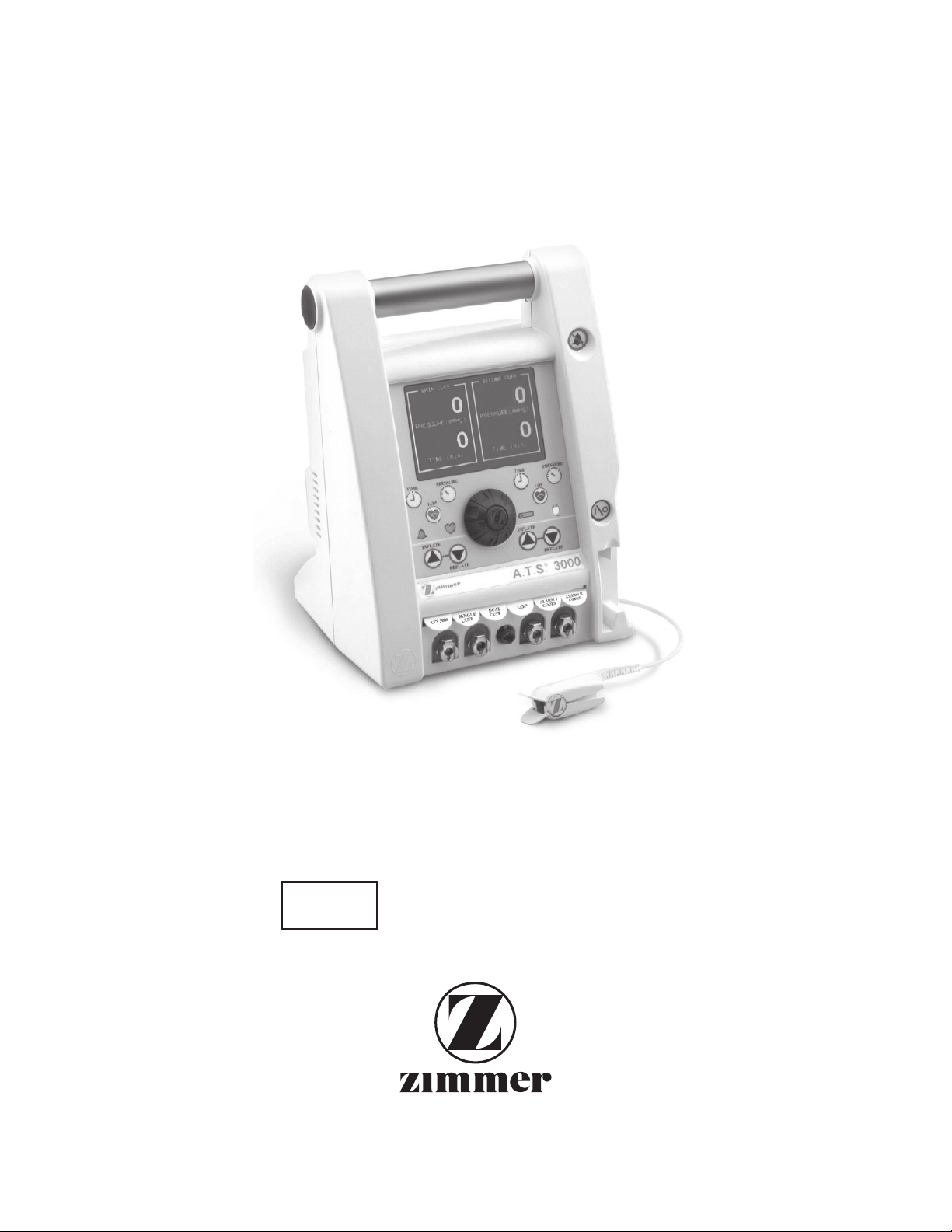
2.2 Controls, Indicators, and Connectors .................................................................................................. 8
2.3 Initial Setup .......................................................................................................................................... 9
2.4 Functional and Calibration Check ....................................................................................................... 9
2.5 Pressure and Time Defaults ................................................................................................................. 11
2.6 Limb Occlusion Pressure (LOP) Determination ................................................................................. 11
2.7 Single Cuff Operation .......................................................................................................................... 13
2.8 Dual Cuff Operation ............................................................................................................................ 14
2.9 Bier Block Cuff Operation (IVRA) ..................................................................................................... 15
2.10 Speaker Volume Setting ....................................................................................................................... 15
2.11 Contrast Display Setting ...................................................................................................................... 15
2.12 Alarm Conditions ................................................................................................................................. 15
3.0 MAINTENANCE
3.1 General Maintenance Information ....................................................................................................... 24
3.2 Access to Parts ..................................................................................................................................... 24
3.3 Limb Occlusion Pressure (LOP) Sensor Cleaning and Disinfecting .................................................. 24
3.4 Periodic Maintenance .......................................................................................................................... 24
3.5 Calibration ............................................................................................................................................ 25
3.6 Leak Testing ......................................................................................................................................... 26
3.7 Battery Voltage and Battery Service .................................................................................................... 27
3.8 Fuse and Fuse Drawer Replacement ................................................................................................... 27
3.9 Unscheduled Maintenance ................................................................................................................... 28
3.10 Troubleshooting Guide ........................................................................................................................ 28
3.11 Expected Test Point Readings ............................................................................................................. 28
3.12 Replacement Parts ................................................................................................................................ 32
3.13 Storage ................................................................................................................................................. 32
3.14 Warnings, Cautions, and Symbology ................................................................................................... 39
1
Page 4

TABLES
A.T.S. 3000 AUTOMATIC TOURNIQUET SYSTEM
2.1 Alarm Conditions ................................................................................................................................. 16
2.2 LOP Alarm Conditions ........................................................................................................................ 18
2.3 Error Codes .......................................................................................................................................... 18
2.4 EMC Guidance and Declaration - EMC Emissions ............................................................................ 20
2.5 EMC Guidance and Declaration - EMC Immunity/Disturbances ....................................................... 20
2.6 EMC Guidance and Declaration - EMC Immunity/RF ....................................................................... 22
2.7 EMC Guidance and Declaration - EMC Immunity/Separation Distances .......................................... 23
3.1 Board Plug Designators ....................................................................................................................... 24
3.2 Troubleshooting ................................................................................................................................... 29
3.3 Expected Test Point Readings ............................................................................................................. 31
3.4 Parts List .............................................................................................................................................. 32
ILLUSTRATIONS
1 A.T.S. 3000 Overview – front ............................................................................................................. 33
2 A.T.S. 3000 Overview – rear ............................................................................................................... 34
3 Main and Second Calibration Kit Setup .............................................................................................. 35
4 Battery Removal Overview ................................................................................................................. 35
5 Rear Power Cord Cover Removal ....................................................................................................... 36
6 Rear Clamp Removal ........................................................................................................................... 36
7 Wiring View of Control Board ............................................................................................................ 36
8 Rear Case Separation ........................................................................................................................... 37
9 Control Board Layout .......................................................................................................................... 38
2
Page 5

GENERAL INFORMATION
A.T.S. 3000 AUTOMATIC TOURNIQUET SYSTEM
SECTION 1.0
ZIMMER A.T.S. 3000 AUTOMATIC TOURNIQUET SYSTEM
1.1 SPECIFICATIONS
Mains Line Voltage Range:
100–240 V ~ (AC), 50/60 Hz. Auto switching
Line Current:
670 mA RMS @ 120 V ~ (AC)
Input Power:
53 Watts typical
Battery Type:
Rechargeable, 12 VDC sealed lead acid,
4.0 amp hours
Battery Discharge Time:
Unit will operate on battery power for 240 minutes minimum
with a fully charged battery.
Battery Recharge Time:
24 hours
Unit should be plugged in 24 hours before initial use.
In the event of a deep battery discharge that cannot be
recovered in the first 24 hours, a second 24 hour charging
period may be required. In this event, the A.T.S. unit should
be unplugged for 60 seconds and reconnected to AC
power prior to starting the second charging session.
Power Cord:
Type SJT or international equivalent of HO5VV-F,
AWG 16 (1.31mm2), 14 ft. (4.27 m)
Power Plug:
Hospital grade, 3 prong straight blade, 15 amp or proper
equivalent power plug
Line Protection:
2 time delayed 1.0 amp 250 volt fuses
CONTROLS:
PRESSURE Button:
PRESSURE
Used in conjunction with the shuttle knob to adjust the
pressure set point. Can also be pressed to verify the set
point. The Main Cuff and Second Cuff have separate
Pressure buttons.
TIME Button:
TIME
Used in conjunction with the Shuttle Knob to adjust the time
alarm set point. Can also be pressed to verify the set point.
The Main Cuff and Second Cuff have separate Time buttons.
Cuff INFLATE / DEFLATE Buttons:
INFLATE
DEFLATE
Controls inflation or deflation of the respective cuff.
The Main Cuff and Second Cuff have separate
DEFLATE
buttons.
INFLATE /
ON/STANDBY Button:
Turns the unit ON / sets unit to STANDBY.
ALARM SILENCE Button:
Allows operator to manually silence most alarms for
30 seconds.
3
Page 6

A.T.S. 3000 AUTOMATIC TOURNIQUET SYSTEM
A.T.S. 3000 AUTOMATIC TOURNIQUET SYSTEM
Limb Occlusion Pressure (LOP) Button:
Cuff Pressure Range:
LOP
Controls the LOP feature. When the pulse sensor is in place
and cuff applied, pressing this button will start the process to
measure the patient’s LOP and give the user a recommended
tourniquet pressure (RTP).
AC Indicator Light Icon (Green LED):
50–475 mmHg, 1 mmHg increments
Pressure Accuracy:
±3 mmHg (50–475 mmHg)
Pressure Regulation:
±4 mmHg of set point
(10 second average under non-transient conditions without
external leaks)
Maximum Pressure:
475 mmHg cuffs
Time Alarm Set Range:
5–240 minutes; 1 minute increments
Timer Accuracy:
0.25% of elapsed time
Indicates unit is operating on AC Mains. This is the normal
means of operation (battery power is only intended for
emergency power loss or patient transport).
Battery Indicator Light Icon (Orange LED):
Indicates unit is operating on backup battery. This indicator
always flashes.
Alarm Indicator Light Icon (Red LED):
Visual indicator to show the unit is in an alarm condition.
LOP Heart Indicator Icon (Yellow LED):
Internal Diagnostics:
Program, memory, watchdog timer, transducer calibration,
improper valve actuation.
SIZE:
Height:
13.0 in. (33.02 cm)
Width:
9.5 in. (24.1 cm)
Depth:
10.375 in. (26.35 cm) (including clamp and ports)
Weight:
16.3 lbs. (7.4
DISPLAYS:
The A.T.S. 3000 uses a backlit 1/4 panel LCD.
Pressure Display: Displays pressure setting, sensed cuff
pressure, and hardware failure conditions / other
messages.
Time Display: Displays time alarm set point, elapsed
time, and hardware failure conditions / other messages.
kg)
Visual indicator to show the LOP function has been invoked.
4
Page 7

A.T.S. 3000 AUTOMATIC TOURNIQUET SYSTEM
UL60601-1 Classification:
Type of protection against electric shock: Class I or Internally Powered Equipment*
Degree of protection against electric shock: Type BF applied part
Classification according to the degree of IPX0
protection against ingress of water:
Mode of operation: Continuous operation
*When the unit is operating on backup battery, the type of protection against electric shock changes to internally powered equipment.
This device is not suitable for use in the presence of flammable anesthetic or gases.
Emissions/Immunity:
The A.T.S. 3000 Tourniquet System complies with EMC criteria set forth in EN 60601-1-2. The user of this device should be
aware that precautions should be taken in regards to EMC. The device should be installed and used according to the EMC
information provided in the instructions for use. See EMC Guidance Tables included in this manual.
Cables
Zimmer LOP sensor cable
Mains power cord
WARNING: use of an LOP sensor cable or mains power cord with a length other than those specified may result in
increased emissions and decreased immunity.
Maximum length
98 inches (249 cm)
170 inches (432 cm)
5
Page 8

A.T.S. 3000 AUTOMATIC TOURNIQUET SYSTEM
A.T.S. 3000 AUTOMATIC TOURNIQUET SYSTEM
1.2 INTENDED USE
The A.T.S. 3000 Tourniquet System is intended to be used by
qualified medical professionals to temporarily occlude blood
flow in a patient’s extremities during surgical procedures
on those extremities. Tourniquets have been found useful in
producing a bloodless operation field in surgical procedures
involving the extremities including:
Reduction of certain fractures
Kirschner wire removal
Tumor and cyst excisions
Subcutaneous fasciotomy
Nerve injuries
Tendon repair
Bone grafts
Total wrist joint replacement
Replacement of joints in the fingers
Knee joint replacements
Amputations
Replantations
WARNING: Do not use tourniquet cuffs to control the
distal flow of CO2 or any other gases used as a distention
media. Tourniquet cuffs have not been evaluated for safety or
effectiveness in controlling gas flow beyond the surgical site
during arthroscopic insufflation procedures. Possible effects
of using a tourniquet cuff in this manner include serious
subcutaneous emphysema proximal to the cuff.
1.3 CONTRAINDICATIONS
The medical literature lists the following as possible
contraindications. However, in every case, the final
decision whether to use a tourniquet rests with the
attending physician.
Open fractures of the leg
Post-traumatic lengthy hand reconstruction
Severe crushing injuries
Elbow surgery (where there is excess swelling)
Severe hypertension
Skin grafts in which all bleeding points must be
readily distinguished
Compromised vascular circulation, e.g., peripheral
artery disease
Diabetes mellitus
The presence of sickle cell disease is a relative
contraindication. (See PRECAUTIONS IN USE.)
A tourniquet should also be avoided in patients who
are undergoing secondary or delayed procedures
after immobilization.
1.4 PRECAUTIONS IN USE
◆ The tourniquet system must be kept well calibrated
and in operable condition. Accessories should be checked
regularly for leaks and other defects.
◆ The tourniquet cuff must never be punctured; therefore
towel clips used near the system must be handled with
special care. Cuffs with inner rubber bladders must be
completely enclosed by the outer envelope to preclude
ballooning and possible rupture of the bladder. Cleaning and
assembly instructions of the cuff manufacturer should be
followed carefully.
◆ Do not use an elastic bandage for exsanguination in
cases where this will cause bacteria, exotoxins, or malignant
cells to spread to the general circulation, or where it could
dislodge thromboemboli that may have formed in the vessels.
◆ The tourniquet cuff must be applied in the proper
location on the limb, for a “safe” period of time, and within
an appropriate pressure range. Never apply a tourniquet
over the area of the peroneal nerve or over the knee or
ankle. Do not readjust an already inflated cuff by rotating it
because this produces shearing forces which may damage the
underlying tissue.
◆ Prolonged ischemia may lead to temporary or permanent
damage to tissues, blood vessels, and nerves. Tourniquet
paralysis may result from excessive pressure. Insufficient
pressure may result in passive congestion of the limb with
possible irreversible functional loss. Prolonged tourniquet
time can also produce changes in the coagulability of the
blood with increased clotting time.
◆ Inflation should be done rapidly to occlude arteries and
veins as near simultaneously as possible.
◆ Careful and complete exsanguination reportedly
prolongs pain free tourniquet time and improves the quality
of Intravenous Regional Anesthesia, (Bier Block anesthesia).
In the presence of infection and painful fractures, after
the patient has been in a cast, and in amputations because
of malignant tumors, exsanguination before tourniquet
application may be done without the use of an elastic
bandage by elevating the limb for 3 to 5 minutes.
◆ In case of failure, the tourniquet cuff must be fully
deflated and the limb exsanguinated again before reinflation.
Reinflation over blood-filled vasculature may lead to
intravascular thrombosis.
◆ Tourniquet users must be familiar with the inflationdeflation sequence when using a dual-cuff tourniquet or two
tourniquet cuffs together for IVRA (Bier Block anesthesia),
so that the wrong tourniquet will not be released accidentally.
◆ Test for hemoglobin type and level before using a
tourniquet on patients with sickle-cell anemia. When the
tourniquet is used for these patients, the limb should be
carefully exsanguinated and the PO
closely monitored.
◆ Select the proper cuff size to allow for an overlap of
about 3 to 6 in. (7.6–15 cm). Too much overlap may cause
cuff rolling and telescoping, and may lead to undesired
and pH should be
2
6
Page 9

A.T.S. 3000 AUTOMATIC TOURNIQUET SYSTEM
pressure distribution on the limb. The skin under the
tourniquet cuff must be protected from mechanical injury by
smooth, wrinkle-free application of the cuff.
If the tourniquet cuff is applied over any material that
may shed loose fibers (such as Webril) the fibers may
become embedded in the contact closures and reduce their
effectiveness. As an under padding, a section of stockinette
may be used. The deflated cuff and any underlying
bandage or protective sleeve should be completely
removed as soon as tourniquet pressure is released.
After the cuff has been fully deflated and removed from
the patient, the unit can be set to STANDBY. Even the
slightest impedance of venous return may lead to congestion
and pooling of blood in the operative field.
◆ If skin preparations are used preoperatively, they should
not be allowed to flow and collect under the cuff where they
may cause chemical burns.
◆ Whenever the tourniquet cuff pressure is released, the
wound should be protected from blood surging back by
applying pressure dressings and, if necessary, elevating the
limb. Transient pain upon tourniquet pressure release can be
lessened by elevation of the limb. If full color does not return
within 3 to 4 minutes after release, the limb should be placed
in a position slightly below body level.
◆ Whenever IVRA, Bier Block anesthesia, is used, it is
recommended that the tourniquet remain inflated for at least
20 minutes from the time of injection.
◆ WARNING: Cuffs will not deflate in STANDBY
mode. Ensure cuffs are fully deflated before setting the
unit to STANDBY.
1.5 ADVERSE EFFECTS
A dull aching pain (tourniquet pain) may develop throughout
the limb following use.
Pathophysiologic changes due to pressure, hypoxia,
hypercarbia, and acidosis of the tissues occur and become
significant after about 1 1/2 hours of tourniquet use.
Symptoms of tourniquet paralysis are motor paralysis
and loss of sense of touch, pressure, and proprioceptive
responses.
Intraoperative bleeding may be caused:
1. By the slight impeding effect exerted by an
unpressurized cuff (and its padding, if used),
which prevents venous return at the beginning of
the operation.
2. By blood remaining in the limb because of
insufficient exsanguination.
3. By inadequate tourniquet pressure (between systolic
and diastolic blood pressure of the patient), or slow
inflation and deflation, all of which allow arterial
blood to enter while preventing venous return.
4. By blood entering through the nutrient vessels of the
long bones, such as the humerous.
7
Page 10

A.T.S. 3000 AUTOMATIC TOURNIQUET SYSTEM
INSTALLATION
AND OPERATING
INSTRUCTIONS
SECTION 2.0
ZIMMER A.T.S. 3000 AUTOMATIC TOURNIQUET SYSTEM
2.1 INITIAL INSPECTION
Unpack the A.T.S. 3000 Tourniquet upon receipt and inspect
the unit for any obvious damage that may have occurred
during shipment. We recommend that this inspection be
performed by a qualified biomedical engineer or other
person thoroughly familiar with electronic medical devices.
If the unit is damaged, notify the carrier and your Zimmer
representative immediately. If the initial inspection results
are satisfactory, a functional and calibration check should
be performed after a 24-hour charge. The attention label
covering the ON/STANDBY button can be removed and
discarded after the 24-hour charge.
2.2 CONTROLS, INDICATORS, AND CONNECTORS
Refer to Figure 1 in the back of the manual for the locations
of the unit’s controls, indicators, and connectors.
1. ON/STANDBY button
Turns the unit ON or sets the unit to STANDBY. This
button will not set the unit to STANDBY when the
cuff pressure is at a non-zero value. Ensure both
cuffs are fully deflated and have been removed
from the patient as well as all underlying bandages
or protective sleeve prior to setting the unit
to STANDBY.
NOTE: During STANDBY, the power to the A.T.S.
3000 instrument and all instrument functions (i.e.
inflation, deflation, etc.) are OFF but power continues
to supply the battery charging circuitry anytime ~ (AC)
power (Mains) is present.
2. Shuttle Knob
Changes the value of set time or default time and set
pressure or default pressure. Turn knob clockwise
to increase the value; turn knob counterclockwise to
decrease the value.
3. PRESSURE button
Press to verify or modify set pressure.
4. TIME button
Press to verify or modify set time.
5. INFLATE buttons
Inflation of the respective cuff is initiated by depressing
the INFLATE button.
6. DEFLATE buttons
Deflation of the respective cuff is initiated by depressing
the DEFLATE button. For greater safety, the DEFLATE
button has a delay and, therefore must be held for
approximately 2 seconds before the unit will allow a cuff
to deflate.
7. ALARM SILENCE button
The ALARM SILENCE button will silence most audible
alarms for 30 seconds after the button is pressed.
When an alarm sounds because of an internal hardware
malfunction, the alarm cannot be silenced.
NOTE: The alarm messages will continue to flash on
the displays until the alarm condition is corrected.
8. AC INDICATOR light
The AC INDICATOR light indicates that the unit is
plugged in and is being powered by AC Mains. This is
the normal means of operation (battery power is only
intended for emergency power loss or patient transport).
9. BATTERY INDICATOR light
The BATTERY INDICATOR light indicates that the
unit is operating on backup battery. The light will
flash continuously while the unit is running on battery
backup power.
10. PRESSURE displays (independent)
During normal operation with no buttons being pressed,
the independent PRESSURE display areas will show the
monitored cuff(s) pressure. At other times, depending on
alarm conditions and buttons pressed, the display may
communicate other information such as alarm messages,
set pressure, or default set pressure.
11. TIME displays (independent)
During normal operation with no buttons being pressed,
the independent TIME display area will show elapsed
inflation time of each cuff. At other times, depending on
alarm conditions and buttons pressed, the display may
communicate other information such as alarm messages,
set time, or default set time.
8
Page 11

A.T.S. 3000 AUTOMATIC TOURNIQUET SYSTEM
A.T.S. 3000 TOURNIQUET SYSTEM
NOTE: The elapsed inflation time can be “zeroed” at
any point in the procedure by pressing the TIME and
PRESSURE buttons for the respective cuff simultaneously.
Cuff connector ports
12.
The
13. Pole Clamp
The Pole Clamp is used to mount the unit on an
NOTE: Do not hang articles on the tourniquet pole that
14. Hose hangers
The A.T.S. 3000 is equipped with hose hangers that
NOTE: Do not hang articles on the tourniquet’s hose
2.3 INITIAL SETUP
Inspect to ensure the correct fuse drawer with the
appropriately rated fuses is present. The 100–120 V unit
uses the gray fuse drawer with 1.0 A time delay fuses.
The 220–240 V unit uses the black fuse drawer with 1.0
A time delay fuses. See Section 3.8 Fuse and Fuse Drawer
Replacement. The power cord should be plugged into the
power entry module on the back of the unit. The unit should
be plugged into ~ (AC) power (Mains) for 24 hours
before initial use. During shipping and storage, the unit’s
battery could become weak. Always charge 24 hours
before any initial use including any calibration checking
procedures, initial checks, tests and any institutional
performed biomedical evaluations.
2.4 FUNCTIONAL AND CALIBRATION CHECK
The unit shall produce the results explained in the following
steps exactly as indicated. Failure to do so indicates that
a problem may exist and the device is not to be used until
necessary repair or calibration has been made.
Cuff connectors are the ports used to connect the
unit to the cuff hoses. Please note that the Main Cuff is
the RED ports and the Second Cuff is the BLUE ports.
The A.T.S. 3000 is designed and tested for use with
Zimmer dual port cuffs. Zimmer does not recommend
the use of any cuff other than Zimmer dual port cuffs.
Do not use single port cuffs with the A.T.S. 3000.
I.V. pole.
are not related to tourniquet use. For stability reasons, do
not use an I.V. pole with a base less than 27.56 inches
(70 cm) in diameter.
pull out of the unit’s handle. The cuff hoses can be
temporarily hung on the hangers for transport or when
disconnecting from the cuff.
hangers that may cause the tourniquet to become
unstable. Cuff hoses or the LOP sensor should be the
only item to utilize the hose hangers.
1. Connect the power plug of the unit to a properly
polarized and grounded power source with voltage
and frequency characteristics compatible with the
specifications listed in Section 1.1.
Observe that the green AC Mains indicator light turns on.
2. Turn the unit ON by pressing the ON/STANDBY button
and observe the following:
a) “Zimmer” along with the circle “Z” appears on the
LCD display.
b) The unit displays “SELF TEST” below the
“Zimmer” name. The unit is self-testing specific
system hardware and software.
c) Emits tones while “SELF TEST” is displayed.
d) The front panel “Alarm”, “LOP”, and “Battery”
indicators flash on and off while “SELF TEST”
is displayed.
e) “CAL” is displayed in the PRESSURE display areas
during the calibration check.
f) “0” is displayed in the PRESSURE and TIME
display areas after the startup routing is complete.
If a number other than zero is displayed in the
PRESSURE display, the unit should be calibrated.
3. Test the PRESSURE set point system as follows:
a) Press either PRESSURE button.
b) The PRESSURE display should read “*250” (the
factory default set point) for approximately 2
seconds.
c) Within the 2 second time frame, rotate the
SHUTTLE KNOB to change the pressure set
point (clockwise to increase, counter-clockwise
to decrease). The set pressure can be maintained
between 50 mmHg and 475 mmHg in increments
of 1 mmHg.
d) Repeat step 3 for the other PRESSURE set point.
4. Test the TIME set point system as follows:
a) Press either TIME button.
b) The main TIME display should read “* 60” (the
factory default set point) for 2 seconds.
c) Within the 2 second time frame, rotate the
SHUTTLE KNOB to change the time set point
(clockwise to increase, counter-clockwise to
decrease). The set time can be maintained between
5 and 240 minutes in increments of 1 minute.
d) Repeat step 4 for the other TIME set point.
NOTE: Anytime an asterisk (*) appears in the left most
display digit, the data being displayed is the set point. Set
pressure and time will revert back to the default pressure and
time settings when the unit is set to STANDBY.
9
Page 12

A.T.S. 3000 AUTOMATIC TOURNIQUET SYSTEM
A.T.S. 3000 AUTOMATIC TOURNIQUET SYSTEM
5. Calibration Check
NOTE: During the power-up diagnostic self-test described
above, the unit will test the calibration. Should an out of
calibration condition be detected, the unit will display either
“CAL” “FAIL”, “CAL M” “FAIL” or “CAL 2” “FAIL” in
the PRESSURE and TIME display areas. Even though the
unit performs this check at every power-up, the following
quantitative check is recommended at regular intervals.
a) Verify the unit is in the STANDBY mode.
b) Enter the calibration mode by pressing then
releasing the ON/STANDBY button then
immediately depress and hold in the Main Cuff
INFLATE and Main Cuff DEFLATE buttons during
power on self test. The unit will enter calibration
mode after momentarily displaying “ZIMMER”
“SELF TEST”. When “CALIBRATION” is
momentarily displayed, release the Main Cuff
INFLATE and Main Cuff DEFLATE buttons. The
unit will also display the software revision level in
the lower left corner. The software revision level can
be recorded for future reference.
NOTE: The calibration is only being checked in this section.
For complete calibration, see Maintenance Section 3.0.
c) Connect a calibrated 0 to 700 mmHg pressure meter
(minimum requirement) to the calibration hose
assembly. The calibrated meter will be used as the
pressure standard (See Figure 3 in the back of the
manual).
d) Connect a pressure source capable of supplying 0 to
700 mmHg of pressure, minimum.
e) Insert one end of the calibration hose assembly
connector into the Main Cuff sense port on the unit
(red port). The sense port is the second port over
from the left side of the unit.
f) Insert the other end of the calibration hose assembly
connector into the Second Cuff sense port on the
unit (blue port). The sense port is the fourth port
over from the left side of the unit.
NOTE: The unit will be displaying “0” where the cuff
pressures are normally displayed and alternating “CAL” and
“0” where the cuff times are normally displayed.
g) Increase the pressure in the calibration hose
assembly to 50 mmHg. Both PRESSURE displays
should read 50±5 mmHg when compared to the
calibrated meter.
h) Increase the pressure to 250 mmHg. Both
PRESSURE displays should read 250±5 mmHg.
i) Increase the pressure to 475 mmHg. Both
PRESSURE displays should read 475±5 mmHg.
j) Decrease the pressure to 0 mmHg and remove
the calibration hose assembly from the unit. The
PRESSURE displays should return to 0 mmHg.
k) Press and hold in the Main Cuff INFLATE and
Main Cuff DEFLATE buttons to advance to the
reservoir calibration check.
NOTE: At this point the reservoir pressure, if pressurized,
will be exhausted through the source ports and the Main
Cuff PRESSURE display should go to “0” while the Main
Cuff TIME display should continue to display “CAL” “0” as
described earlier.
l) Insert one end of the calibration hose assembly
connector into the Main Cuff source port on the
unit (red port). The source port is the first port from
the left side of the unit.
m) Insert the other end of the calibration hose assembly
connector into the Second Cuff source port on the
unit (blue port). The source port is the third port
over from the left side of the unit.
n) Increase the pressure in the calibration hose assembly
to 250 mmHg. The display should read 250±5 mmHg.
o) Increase the pressure to 475 mmHg. The display
should read 475±5 mmHg.
p) Increase the pressure to 700 mmHg. The display
should read 700±5 mmHg.
NOTE: If any reading is off by more than ±5 mmHg, the
entire unit must be recalibrated by following the calibration
procedure as outlined in Maintenance Section 3.0.
q) To complete this procedure, turn the unit OFF by
holding in the ON\STANDBY button until the unit
is set to STANDBY.
r) Calibration check is complete.
6. Low Pressure Alarm Check –
Turn the unit ON by pressing the ON/STANDBY button.
Connect a cuff and standard length hose set to the Main
Cuff ports. Inflate the cuff to 250 mmHg. Create a
leak in the cuff by partially detaching the hose (either
port) from the unit while a cuff is inflated. Make the
leak large enough that the pressure drops more than
15 mmHg below set point. Observe:
a) A 1.5 second delay is instituted to reduce nuisance alarms.
b) The PRESSURE display flashes between “LO-P” and
the monitored pressure (if a substantial leak has been
present for more than 9 seconds, the PRESSURE display
will show “CUFF” “LEAK”).
c) An audible tone will sound and the red alarm indicator
will illuminate announcing the alarm condition.
10
Page 13

A.T.S. 3000 AUTOMATIC TOURNIQUET SYSTEM
A.T.S. 3000 AUTOMATIC TOURNIQUET SYSTEM
d) Stop the leak and observe the monitored pressure
returns to regulated state, the audible tone stops, the red
alarm indicator turns off, and the alarm message is no
longer displayed.
Repeat this procedure with the Second Cuff ports.
2.5 PRESSURE AND TIME DEFAULTS
To modify the default pressure or time limits for either cuff,
follow the following steps.
1. Default Pressure
a) The Default Pressure is selected by depressing and
holding either PRESSURE button for 2 seconds.
When the default mode is entered, the audible
alarm beeps once and a “D” is displayed in the first
position on the selected cuff PRESSURE display.
b) The Default Pressure is modified via the
and can be set between 50 and 475 mmHg in
Knob
increments of 1 mmHg.
c) After the correct value is selected, it is saved by
momentarily depressing the PRESSURE button or it
will be saved automatically in 3 seconds.
d) The new default value will be displayed for
1.5 seconds and the audible alarm will beep once
signifying a new default value has been stored.
e) The new default pressure will be stored and remains
the default every time the machine is turned on.
2. Default Time Limit
a) The Default Time Limit is selected by pressing and
holding either TIME button for 2 seconds. When
the default mode is entered the audible alarm beeps
and a “D” is displayed in the first position on the
selected cuff TIME display.
b) The Default Time Limit is modified via the Shuttle
Knob and can be set between 5 and 240 minutes in
increments of 1 minute.
c) After the correct value is selected, it is saved by
momentarily depressing the TIME button or it will
be saved automatically in 3 seconds.
d) The new default value will be displayed for
1.5 seconds and the audible alarm will beep once
signifying a new default value has been stored.
e) The new time limit default will be stored and
remains the default every time the machine is
turned ON.
NOTE: The elapsed inflation time can be “zeroed” at
any point in the procedure by pressing the TIME and
PRESSURE buttons simultaneously for each respective
cuff time.
Shuttle
2.6 LIMB OCCLUSION PRESSURE (LOP)
DETERMINATION
NOTE: Limb Occlusion Pressure (LOP) determination is not
intended for use in pediatric procedures.
The patient’s limb occlusion pressure is the lowest pressure
required to stop the flow of blood in the extremity. The A.T.S.
3000 has the ability to estimate the patient’s limb occlusion
pressure based on their physiological characteristics. The
A.T.S. 3000 will also take into account anticipated changes in
blood pressure during the procedure by adding an additional
pressure margin to the LOP measurement at the end of the
LOP determination. This additional pressure margin added
to the LOP measurement is referred to as the Recommended
Tourniquet Pressure or RTP. The RTP is calculated using the
LOP with the following:
LOP 100–130 mmHg LOP + 50 mmHg = RTP
LOP 131–190 mmHg LOP + 75 mmHg = RTP
LOP 191–300 mmHg LOP + 100 mmHg = RTP
The RTP can be accepted or rejected based on the
physician’s discretion. The RTP value is presented at the end
of the LOP determination.
When deciding to accept the RTP value or not the physician
may take into account other factors such as the patient’s
blood pressure, anesthetic technique to be used, expected
procedure duration, cuff location, cuff type, cuff width,
snugness of cuff application and surgical procedure to
be performed. The physician may also choose to use an
alternative method such as the Doppler stethoscope to
manually determine the patient’s LOP, or to confirm the
LOP determined by the A.T.S. 3000. The accuracy of the
automatic determination of LOP can be verified manually, by
employing a Doppler stethoscope and carefully following the
published technique for manual LOP determination.
The A.T.S. 3000 will suggest the RTP as the lowest pressure
for the extremity to ensure the field will remain clear even
during changes in blood pressure. However large changes
in the patient’s blood pressure during surgery may result in
reduced visibility in the field. The pressure may need to be
adjusted slightly to improve visual quality. The RTP may
be overridden at any time simply by changing the pressure
set point.
11
Page 14

A.T.S. 3000 AUTOMATIC TOURNIQUET SYSTEM
It should be noted that certain physiologic conditions in
some patients may prevent the A.T.S. 3000 from making
a determination of LOP, in which case the instrument
will display an appropriate message and will terminate
the attempt to measure LOP. In that event, the physician’s
judgment should be used to set tourniquet pressure in the
absence of LOP and RTP values.
The determination of LOP is intended as additional,
supplementary information for the physician responsible
for selecting the tourniquet pressure to be employed for a
specific patient and procedure. The physician’s best judgment
should always be paramount in the selection of tourniquet
pressure.
NOTE: The pulse sensor appears very similar to other
sensors used for pulse measurements. It should be noted,
the A.T.S. 3000’s pulse sensor does not measure oxygen
saturation nor can it be modified to do so. The A.T.S. 3000
uses a custom sensor. Non Zimmer sensors will not work
with the A.T.S. 3000. Use of a non Zimmer sensor could
damage the A.T.S. 3000 or cause unpredictable operation.
Never use any sensor other than approved Zimmer
pulse sensors.
2.6.1 Single Bladder Cuff LOP Measuring
NOTE: If the LOP determination is performed on the Main
Cuff, all readings and recommendations are for the Main
Cuff only. If the LOP determination is performed on the
Second Cuff, all readings and recommendations are for the
Second Cuff only.
c) Connect the LOP pulse sensor to the LOP socket in the
front of the A.T.S. 3000.
d) Prepare the patient in accordance with your established
procedures and cuff manufacturer’s instructions. The
precautions of Section 1 and the following are offered as
a guide to assist in this process.
In most cases a tourniquet cuff should be applied to
the widest part of the limb to allow as much tissue
as possible to lie between the cuff and any nerves or
vascular structures susceptible to damage. The optimum
positions are the upper arm and the proximal third
of the thigh. In certain cases of fore-foot surgery, the
tourniquet cuff can be applied around the calf or to the
area proximal to the malleoli. The valve port and hose
connections should be placed so that the hose will not be
kinked when the limb is positioned for surgery.
e) Attach the LOP pulse sensor to the patient’s index
finger or second toe on which the tourniquet cuff has
been applied.
NOTE: LOP determination temporarily inflates then deflates
the tourniquet cuff automatically to obtain the patient’s LOP.
a) Press the ON/STANDBY button to turn the unit ON.
The unit will execute a self-check diagnostic test as
described in Section 2.4 of this manual. Successful
completion of the self-check indicates the unit is ready
for use.
CAUTION: If a connected cuff is pressurized to
50 mmHg or more during power-up, the A.T.S. 3000
Tourniquet will declare it an abnormal start-up sequence.
It will assume that a surgical procedure is in process,
and will adopt the pressure sensed in the cuff as the new
set point. It will automatically go into the regulate mode
on the cuff. To alert the operator of this condition, the
unit will sound a tone and display a “CUFF” “INFL”
alarm. The operator should immediately check the
pressure set point and readjust to the proper set point if
necessary. The alarm will be cleared as soon as the set
point is examined, (press the correct pressure button).
b) Connect a dual port cuff to the unit at the Main Cuff or
Second Cuff port connectors. The Main Cuff and Second
Cuff both have the ability to perform the LOP function.
NOTE: The LOP Pulse Sensor is applied to a finger or toe
on the operative limb.
f) Ensure the sensor is fully engaged to achieve the best
possible and most accurate reading.
g) With the cuff and sensor applied to the patient, press the
corresponding LOP icon to start the LOP determination.
The A.T.S. 3000 will begin to inflate the cuff
incrementally while continuously analyzing the patient’s
pulse. If the sensor or cuff were not properly installed,
the unit will display alarm messages. The meanings to
the alarm messages are found in Table 2.2.
h) The LOP determination will last approximately
30 seconds depending on the quality of pulse sensed.
i) At the end of the LOP determination, the A.T.S. 3000
will beep and display the LOP and RTP pressures
in the lower display area for that cuff. The unit will
automatically display the RTP in the cuff pressure
display area preceded by a “*”.
NOTE: The RTP is the summation of the pressure margin
and the LOP which ensures the field visibility remains clear
during the procedure.
j) To accept the RTP and return to normal operation
press the corresponding PRESSURE button. To reject
12
Page 15

A.T.S. 3000 AUTOMATIC TOURNIQUET SYSTEM
the RTP value and enter a user defined pressure value,
turn the
Section 2.4.3.c.
k) To retry the LOP procedure, repeat section 2.6 steps
f thru i.
NOTE: The A.T.S. 3000 will not automatically inflate the
cuff at the end of the LOP determinations. It is the user’s
responsibility to accept or reject the RTP.
l) If the RTP is acceptable and no other adjustments are
required, pressing the respective INFLATE button will
inflate the cuff to the RTP.
m) In the event the quality of visibility is reduced by
an increase in patient blood pressure, the tourniquet
pressure can be increased manually. To increase the
tourniquet pressure manually, momentarily press the
corresponding PRESSURE button and rotate the
Knob clockwise to increase the pressure set point.
n) After the LOP has been measured and the unit has
offered an RTP, the unit is ready to be used. However,
the user need not perform a LOP measurement to use the
tourniquet system.
NOTE: The LOP is only used to obtain patient LOP prior
to tourniquet use. Once the patient LOP measurement is
complete, remove the LOP sensor from the patient and store.
2.6.2 Dual Bladder Cuff LOP Measuring
NOTE: LOP determination temporarily inflates then deflates
the tourniquet cuff automatically to obtain the patient’s LOP.
LOP measurement for a dual bladder cuff is identical to a
single bladder cuff except for the following points:
1. A dual bladder dual port cuff is connected to the unit
(Reminder: Main Cuff is the Red ports, Second Cuff is
the Blue ports).
2. At the end of the LOP determination using the first
bladder, press the corresponding PRESSURE button to
accept the RTP for that cuff.
3. Initiate an LOP determination using the second bladder
by pressing the corresponding LOP button.
4. At the end of the LOP determination using the second
bladder, the RTP will appear in the corresponding
pressure display area preceded by a “*”.
5. Compare the RTP currently being displayed with the
RTP that was accepted in step 2 above.
NOTE: The RTP accepted in step 2 above is now
the pressure set point for that cuff. To verify the RTP,
momentarily press the corresponding PRESSURE button.
During this activity the RTP in step 4 will temporarily
Shuttle Knob and follow the procedure in
Shuttle
be “cleared” from the display but will return following a
3-second delay.
6. If the RTP from the first LOP determination is higher
than the second RTP, turn the Shuttle Knob and follow
the procedure in Section 2.4.3.c to adjust the second
RTP to equal the first RTP.
7. If the RTP from the first LOP determination is
lower than the second RTP, press the corresponding
PRESSURE button to accept the RTP from the second
LOP determination. Next, follow the procedure in
Section 2.4.3.c to adjust the first RTP to equal the
second RTP.
2.7 SINGLE CUFF OPERATION
1. Press the ON/STANDBY button to turn the unit ON.
The unit will execute a self-check diagnostic test as
described in Section 2.4 of this manual. Successful
completion of the self-check indicates the unit is ready
for use.
CAUTION: If a connected cuff is pressurized to 50 mmHg
or more during power-up, the A.T.S. 3000 Tourniquet will
declare it an abnormal start-up sequence. It will assume
that a surgical procedure is in process, and will adopt the
pressure sensed in the cuff as the new set point. It will
automatically go into the regulate mode on the cuff. To alert
the operator of this condition, the unit will sound a tone
and display a “CUFF” “INFL” alarm. The operator should
immediately check the pressure set point and readjust to
the proper set point if necessary. The alarm will be cleared
as soon as the cuff set point is examined, (press the correct
PRESSURE button).
2. Connect a dual port cuff to the unit at the Main Cuff
connectors (red ports).
3. The default settings for cuff pressure and time limit are
retrieved from the nonvolatile memory during power up.
For each patient, tourniquet pressure required to occlude
blood flow to the operative site should be set to the
minimum effective pressure. The minimum effective
pressure should be determined by factors such as:
whether the cuff is to be applied to an upper or lower
limb; whether the limb is normal, hypertrophied, or
obese; the patient’s preoperative systolic pressure;
and the maximum anticipated rise in systolic pressure
during the procedure. The A.T.S. 3000 has the unique
ability to estimate the minimum effective pressure. This
pressure is referred to as the Limb Occlusion Pressure
or LOP. Refer back to Section 2.6 for using the LOP
measuring feature.
13
Page 16

A.T.S. 3000 AUTOMATIC TOURNIQUET SYSTEM
4. Prepare the patient in accordance with your established
procedures and cuff manufacturer’s instructions. The
precautions of Section 1 and the following are offered as
a guide to assist in this process.
In most cases a tourniquet cuff should be applied to
the widest part of the limb to allow as much tissue
as possible to lie between the cuff and any nerves or
vascular structures susceptible to damage. The optimum
positions are the upper arm and the proximal third of the
thigh. In certain cases of fore-foot surgery, the tourniquet
cuff can be applied around the calf or to the area
proximal to the malleoli. For emergency surgery of the
hand, a sufficiently small tourniquet can be fitted around
the wrist.
Apply a leak-free tourniquet cuff smoothly without
wrinkles. The valve port and hose connections should
be placed so that the hose will not be kinked when
the limb is positioned for surgery. The viability of the
skin and deeper tissues should be established prior to
exsanguination of the limb and tourniquet inflation.
Exsanguinate the limb by elevating it for a minimum of
2 minutes and wrapping it, distal to proximal, using an
Esmarch, Martin, or elastic bandage. The bandage should
come up approximately to 1 in. (2.5 cm) from the edge
of the tourniquet cuff. The elastic bandage is removed
following inflation of the cuff. If regional anesthesia is
being used, the anesthetic agent or nerve block is then
administered. The tourniquet time depends greatly on the
patient’s anatomy, age, and absence of vascular disease.
The surgeon will determine:
1) When the tourniquet is to be inflated;
2) What pressure is applied;
3) How long the tourniquet is applied;
4) Whether to allow for intermittent aeration of tissue
by deflating the cuff for 10 to 15 minutes;
5) To what point in the operation the tourniquet should
be released.
In many operating rooms, it is customary to prominently
note the time of inflation, and to warn the surgeon after
a certain time has elapsed. This will allow the surgeon to
assess the need for further tourniquet time.
There is a general agreement that, for reasonably healthy
adults, 2 hours should not be exceeded without releasing
the tourniquet to allow the underlying tissue to breathe.
During this time, the limb should be elevated to about
60 degrees, and steady pressure should be applied to the
incision with sterile dressings.
5. The cuff is inflated by pressing the red Main Cuff
INFLATE button. The unit will pressurize the Main
Cuff to the set pressure and start the elapsed inflation
time alarm clock. The Main Cuff inflation information
will be displayed on the LCD screen. If the unit cannot
pressurize the cuff to within 15 mmHg of the set point
in less than 30 seconds, a leak alarm will be sounded.
See Section 2.12 for information about possible alarm
conditions. Once the cuff is inflated, the time display
will track elapsed inflation time.
6. At the end of the procedure, deflate the cuff by pressing
the Main Cuff DEFLATE button for minimum of
2 seconds. The Main Cuff PRESSURE display will show
the deflation of the cuff and the elapsed inflation time
alarm clock will stop.
NOTE: The elapsed inflation time can be “zeroed”
at any point by pressing the TIME and PRESSURE
buttons simultaneously.
7. Remove the tourniquet cuff and any underlying
bandages or protective sleeve immediately following
final deflation. The time of tourniquet cuff removal
should be noted, and the circulation of the limb should
be checked.
8. After the cuff has been removed, disconnect the cuff
from the A.T.S. 3000.
9. During normal use, the A.T.S. 3000 should not be set to
STANDBY if pressure is present in either cuff. Once
the cuff has been properly deflated, removed from the
patient, and disconnected from the A.T.S. 3000, the unit
can be set to STANDBY.
2.8 DUAL CUFF OPERATION
Operation of the unit is identical to Single Cuff operation
(see Section 2.7) except for the following points:
1. Two dual port cuffs are connected to the unit (Reminder:
Main Cuff is the Red ports, Second Cuff is the
Blue ports).
2. The Main and Second LCD screen section will display
inflation information and begin timing the cuff inflation.
3. Deflation of one cuff will not be permitted while the
other cuff is inflating.
4. When inflating a second cuff with the other cuff already
inflated, the unit will continuously check the original
cuff to ensure that the pressure is within allowable limits.
The unit will stop its inflation and maintain the original
cuff to within 10 mmHg of the set point before returning
to the inflating cuff. This ensures that at least one cuff
maintains occlusion at all times. If there is a significant
leak in the original cuff, this feature could cause the
inflation rate of the subsequent cuff to be longer and
perhaps even cause the 30-second inflation alarm
to sound.
14
Page 17

A.T.S. 3000 AUTOMATIC TOURNIQUET SYSTEM
5. When both cuffs are inflated, the LCD screen displays
independent information for each cuff. That is, the
PRESSURE and TIME displays are independently
operated and controlled for each cuff.
6. In order to deflate the final cuff, a sequence must be
followed to prevent accidental deflation:
a) Press and hold the DEFLATE button on the cuff to
be deflated;
b) When the “CUFF” “DEFL” alarm is active,
release the DEFLATE button;
c) Within 5 seconds of the alarm discontinuing, press
the DEFLATE button once again;
d) The cuff will deflate. This safety feature is
particularly useful when using the unit for Bier
Block Cuff Operation, (IVRA).
2.9 BIER BLOCK CUFF OPERATION (IVRA)
Review Sections 2.7 and 2.8, SINGLE CUFF OPERATION
and DUAL CUFF OPERATION.
1. The following are suggested cuff connections:
a. The proximal cuff connected to the Red Main Cuff
ports using the white/red cuff tubing;
b. The distal cuff connected to the Blue Second Cuff
ports using the white/blue cuff tubing.
2. Follow the cuff inflation sequence adopted by your
institution or requested by the surgeon.
3. Deflation of a cuff is not possible while the other
is inflating.
4. When requested, the first can be deflated simply by
pressing and holding the DEFLATE button for a minimum
of 2 seconds.
5. In order to deflate the final cuff, a sequence must be
followed to prevent accidental deflation:
a) Press and hold the DEFLATE button on the cuff to
be deflated;
b) When the “CUFF” “DEFL” alarm is active,
release the DEFLATE button;
c) Within 5 seconds of the alarm discontinuing, press
the DEFLATE button once again;
d) The cuff will deflate.
6. For Bier Block procedures follow the cuff inflation/
deflation sequence adopted by your institution or
requested by the surgeon.
2.10 SPEAKER VOLUME SETTING
An operator may want to change the speaker volume setting
from the default. The following steps will allow a user to
customize the speaker volume default setting.
1. Press the ON/STANDBY button to turn the unit ON. The
unit will execute a self-check diagnostic test as described
in Section 2.4.
2. Press and hold both the Main Cuff TIME and Main Cuff
PRESSURE buttons for approximately 3 seconds.
3. When the volume selection screen appears, the user can
adjust the volume up or down by turning the
. Clockwise rotation increases volume while a
Knob
counterclockwise rotation decreases volume. With every
increment or decrement the speaker will sound to give the
user feedback of the volume level setting selected. After
5 seconds of inactivity the system will accept the volume
setting as displayed and return the display back to its
normal mode of operation.
4. The user can accept the volume setting by pressing the
Main Cuff PRESSURE button which stores the setting
and returns the display to its normal mode. Or, wait
approximately 5 seconds as noted above to allow the
system to accept the new volume setting.
2.11 CONTRAST DISPLAY SETTING
An operator may want to change the display contrast setting
from the default. The following steps will allow a user to
customize the display contrast default setting.
1. Press the ON/STANDBY button to turn the unit ON. The
unit will execute a self-check diagnostic test as described
in Section 2.4.
2. Press and hold both the Second Cuff TIME and Second
Cuff PRESSURE buttons for approximately 3 seconds.
3. When the contrast control setting selection screen appears,
the user can adjust the display contrast by turning the
Shuttle Knob. Clockwise rotation increases display
contrast while a counterclockwise rotation decreases
display contrast. With every increment or decrement the
display will show the new contrast setting selected. After
approximately 5 seconds of inactivity the system will
accept the contrast control setting as displayed and return
the display back to its normal mode of operation.
4. The user can accept the new setting by pressing the
Second Cuff PRESSURE button which stores the setting
and returns the display to its normal mode. Or, wait
approximately 5 seconds as noted above to allow the
system to accept the setting.
2.12 ALARM CONDITIONS
There are a number of conditions for which the A.T.S. 3000
Tourniquet will produce a visual and/or audible alarm. Those
conditions, indications, and appropriate actions are shown
in Table 2.1. The appropriate actions indicated are based on
the most probable causes and should only be used as a guide.
Other causes of alarm conditions may indicate a need for other
actions. In addition to the conditions shown in Table 2.1, it
is conceivable that a malfunction could occur for which
the indications are unintelligible and unpredictable. In this
Shuttle
15
Page 18

A.T.S. 3000 AUTOMATIC TOURNIQUET SYSTEM
situation, it is likely that the valves will be disabled causing
the system to hold cuff pressure. It is also likely that a tone
will sound under these conditions. Most audible alarm tones
may be silenced for 30 seconds by pressing the ALARM
SILENCE button. The tone will be re-enabled at the end of
the silenced period. Pressing the ALARM SILENCE button
will cause the alarm tone to be silenced again.
The A.T.S. 3000 Tourniquet will also provide Error Code
information for critical alarms as shown in Table 2.3.
To minimize nuisance alarms (i.e. “HI-P”, “LO-P”) that can
be caused by vigorous movement of the patient’s limbs, a
1.5-second delay has been designed into the alarm actuation.
Under certain conditions, such as when a FAIL indication
appears in the TIME display or the information that appears
in the TIME and PRESSURE displays is unintelligible,
the operator should conclude that a hardware failure has
occurred, rendering the unit unusable. The appropriate
action is to set the unit to STANDBY by pressing the ON/
STANDBY button. Since this removes power from the
internal instrument circuitry, all instrument functions,
commands to the valves and pump will cease. This
Table 2.1 Alarm Condition
CONDITION PRESSURE
DISPLAY
will cause the cuff to hold pressure (in the absence of
leaks). Clamp the cuff lines with hemostats and replace the
tourniquet unit.
2.12.1 PRESSURE ALARMS
A pressure alarm will occur when the pressure in a cuff is
more than 15 mmHg from the pressure set point. It is also
possible for a cuff to have a leak that is substantial but which
the unit can compensate for by continual pumping. This type
of leak could be due to a pin hole in a cuff bladder, or a loose
pneumatic fitting. This type of leak could progress into a
total failure of a cuff to hold pressure. To alert the operator
that a substantial leak is present, a pressure alarm is declared
when this type of leak is continuously present for more than
9 seconds. If a pressure alarm occurs, and the displayed
pressure is not more than 15 mmHg from the set point, then
this type of substantial leak has been detected and all cuffs
and pneumatic fittings should be checked for leaks.
TIME
DISPLAY
APPROPRIATE ACTION/REMARKS
CUFF PRESSURE LOW
The pressure in the cuff is
15 mmHg below set point
CUFF PRESSURE HIGH
The pressure in the cuff is
15 mmHg above set point
CUFF SIDE LEAK
A leak has been present for at least
9 seconds.
RESERVOIR LEAK
A leak is present between the pump
and valves
INFLATION TIME IN EXCESS
OF SETTING
The cuff has been inflated beyond
the set time limit
CUFF INFLATION ON
POWER UP
Cuff pressurized to 50 mmHg or
greater at power up
CUFF NOT DEFLATED
Pressure in deflated cuff is a nonzero value
LO-P normal This condition is generally caused by a leak in
the system, or a hose occlusion. All lines and
connections should be checked.
HI-P normal Normally caused by transient conditions such as
patient movement, controller overshoot, or hose
occlusion. This condition, for an extended period,
would indicate a hardware failure and the A.T.S.
3000 unit should be replaced.
CUFF LEAK normal A substantial leak has been present for more
the 9 seconds. All lines and connections should be
checked.
RES LEAK normal Do not use the unit. Service the unit.
normal TIME UP Surgeon should be warned of time up condition.
Only on the direction of the surgeon, time should
be set to new value.
CUFF INFL The system assumes that a procedure is in progress
and adopts the sensed pressure as the new set point.
The operator should immediately check the set
value to determine if it needs reset.
normal CUFF NOT
DEFL
Check for kinks in hose. If alarm persists,
disconnect hose from cuff. If attempting to
set the unit to STANDBY, ensure that cuff is
fully deflated.
16
Page 19

A.T.S. 3000 AUTOMATIC TOURNIQUET SYSTEM
Table 2.1 Alarm Condition
CONDITION PRESSURE
LINE OCCLUSION
An occlusion is present in the
cuff tubing
LOW BATTERY VOLTAGE
Low battery voltage
CHECK CUFF
An increase in cuff pressure has not
been sensed within 1 second after
depressing the inflate key
BATTERY FAILURE
Battery voltage is too low to ensure
proper operation
CALIBRATION OUT OF SPEC
The transducer calibration is out
of specification
CALIBRATION OUT OF SPEC
A transducer calibration is out
of specification
AMPLIFIER FAILURE
Amplifier is out of range
MATH FAILURE
Result of math operation was out
of range
ROM FAILURE
Microprocessor failed a ROM
memory check
RAM FAILURE
Microprocessor failed a RAM
memory check
VALVE FAILURE
Improper valve combination
occurred
WATCHDOG FAILURE
Windowing watchdog system
detected a malfunction
SYSTEM FAILURE SYSTEM FAIL Cycle the ON/STANDBY Button. If problem
Continued
TIME
DISPLAY
LINE OCCL normal Check for hose kinks or other defects.
normal BATT LOW
CHK CUFF Check to see that a cuff and hose assembly is
BATTERY FAIL Plug unit in and cycle the ON/STANDBY Button.
CAL M or CAL 2
CAL FAIL Indicates general calibration fail. Calibrate the unit.
AMP FAIL Cycle the ON/STANDBY Button. If problem persists,
MATH
VA LV E
DISPLAY
PLUG IN
FAIL
FAIL
ROM
FAIL
RAM
FAIL
FAIL
WDT
FAIL
APPROPRIATE ACTION/REMARKS
Plug unit in. If the unit is not plugged in, a battery
failure condition will occur and the unit will shut down
in a fail safe mode closing all valves. While running
with a Low Battery Voltage Alarm Condition other
alarm conditions can not be guaranteed.
connected to the proper ports on the unit.
CAL M (CALIBRATION MAIN) or CAL 2
(CALIBRATION SECOND) indicates a cuff
transducer circuitry is out of calibration. Pressure in
error by at least 6 mmHg will cause these failures.
Calibrate the unit.
service the unit.
Cycle the ON/STANDBY Button. If problem
persists, service the unit.
Cycle the ON/STANDBY Button. If problem
persists, service the unit.
Cycle the ON/STANDBY Button. If problem
persists, service the unit.
Cycle the ON/STANDBY Button. If problem
persists, service the unit.
Cycle the ON/STANDBY Button. If problem
persists, service the unit.
persists, service the unit.
17
Page 20

A.T.S. 3000 AUTOMATIC TOURNIQUET SYSTEM
Table 2.2 LOP Alarm Condition
CONDITION PRESSURE
DISPLAY
No LOP pulse sensor detected
during LOP
Message displayed at bottom
of display area.
“CONNECT LOP SENSOR”
LOP pulse sensor not properly
secured to patient normal
normal
normal TIME OUT
Cuff is leaking or not connected
to unit or connected to incorrect
normal CUFF INFL
port during LOP function
Patient LOP is too high for LOP
measurement normal HIGH LOP
LOP pulse sensor attached to
incorrect limb normal
LOP procedure stopped
normal STOP
TIME
DISPLAY
CHECK
SENSOR
LOW
SIGNAL
CHECK
SENSOR
APPROPRIATE ACTION/REMARKS
Plug LOP pulse sensor in. Reattach LOP pulse sensor and
retry. Replace LOP pulse sensor with known good working
sensor and retry. If problem persists, service the unit.
Check LOP pulse sensor and retry. Replace LOP pulse sensor
with known good working sensor and retry. If problem persists,
service the unit.
Check LOP pulse sensor and retry. Replace LOP pulse sensor
with known good working sensor and retry. If problem persists,
service the unit.
Check LOP pulse sensor and retry. Replace LOP pulse sensor
with known good working sensor and retry. If problem persists,
service the unit.
Check cuff for leaks and retry. Connect cuff to correct port and
retry. Connect cuff to unit and retry. If problem persists, service
the unit.
Check LOP pulse sensor and retry. Replace LOP pulse sensor
with known good working sensor and retry. Do not use the
LOP function, follow normal tourniquet procedures.
Attach LOP pulse sensor to correct limb and retry.
Replace LOP pulse sensor with known good working
sensor and retry. If problem persists, service the unit.
A front panel button may have been pressed while in the LOP
function. Wait for the message to clear and retry. If problem
persists, service the unit.
NOTE: 1 Some Error Codes are followed by a four-digit numeric code. This code represents detailed
Table 2.3 Error Codes
information related to the failure. Contact the manufacturer for information concerning those specific codes.
ERROR CODE CRITICAL FAILURE EXPLANATION/APPROPRIATE ACTIONS
A timing error was detected during self-test. Cycle the ON/
E001 XXXX
1
SYSTEM FAIL
STANDBY button. If problem persists, note error code and contact
manufacturer.
E002 XXXX
1
SYSTEM FAIL
A Safety Monitor signal error was detected. Cycle the ON/STANDBY
button. If problem persists, note error code and contact manufacturer.
A pneumatic system error was detected during self-test. Cycle the
E003 SYSTEM FAIL
ON/STANDBY button. If problem persists, note error code and
contact manufacturer.
A Safety Monitor timing error was detected. Cycle the ON/
E004 WDT FAIL
STANDBY button. If problem persists, note error code and contact
manufacturer.
The Safety Monitor detected an illegal valve state. Cycle the ON/
E005 VALVE FAIL
STANDBY button. If problem persists, note error code and contact
manufacturer.
18
Page 21

A.T.S. 3000 AUTOMATIC TOURNIQUET SYSTEM
Table 2.3 Error Codes
ERROR CODE CRITICAL FAILURE EXPLANATION/APPROPRIATE ACTIONS
E006 SYSTEM FAIL
E007
E008 SYSTEM FAIL
E010 ROM FAIL
E011 ROM FAIL
E012 RAM FAIL
E013 BATTERY FAIL
E014 BATTERY FAIL
E015 CAL FAIL
E016 CAL FAIL
E017 CAL FAIL
E018 CAL M FAIL
E019 CAL 2 FAIL
E020 XXXX
E021 XXXX
E022 XXXX
E023 XXXX
E024 XXXX
E025 XXXX
E026 XXXX
E027 XXXX
1
1
1
1
1
1
1
1
Continued
MATH FAIL
SYSTEM FAIL
AMP FAIL
AMP FAIL
AMP FAIL
AMP FAIL
AMP FAIL
AMP FAIL
SYSTEM FAIL
A Safety Monitor detection error was detected. Cycle the ON/
STANDBY button. If problem persists, note error code and contact
manufacturer.
A processor error was detected. Cycle the ON/STANDBY button. If
problem persists, note error code and contact manufacturer.
The processor received an unknown interrupt. Cycle the
ON/STANDBY button. If problem persists, note error code and
contact manufacturer.
A non-volatile memory value was detected during power-up.
Cycle the ON/STANDBY button. If problem persists, note error
code and contact manufacturer.
ROM check error detected a self-test. Cycle the ON/STANDBY
button. If problem persists, note error code and contact manufacturer.
A microprocessor RAM error was detected during self-test. Cycle
the ON/STANDBY button. If problem persists, note error code and
contact manufacturer.
Battery voltage below minimum threshold. Plug unit in and cycle
the ON/STANDBY button. If problem persists, note error code and
contact manufacturer.
A battery charging circuit failure was detected at power-up. Verify a
battery is connected and cycle the ON/STANDBY button. If problem
persists, note error code and contact manufacturer.
Incorrect zero pressure calibration point was detected. Calibrate unit.
If problem persists, note error code and contact manufacturer.
Incorrect calibration point was detected. Calibrate unit. If problem
persists, note error code and contact manufacturer.
Calibration error was detected. Calibrate unit. If problem persists, note
error code and contact manufacturer.
Main cuff transducer calibration error was detected. Calibrate unit. If
problem persists, note error code and contact manufacturer.
Second cuff transducer calibration error was detected. Calibrate unit.
If problem persists, note error code and contact manufacturer.
A software exception error was detected. Cycle the ON/STANDBY
button. If problem persists, note error code and contact manufacturer.
A transducer reference voltage is out of range. Calibrate unit. If
problem persists, note error code and contact manufacturer.
Reservoir transducer is out of range. Calibrate unit. If problem
persists, note error code and contact manufacturer.
The Main cuff transducer is out of range. Calibrate unit. If problem
persists, note error code and contact manufacturer.
The Second cuff transducer is out of range. Calibrate unit. If problem
persists, note error code and contact manufacturer.
A voltage level is out of range. Cycle the ON/STANDBY button. If
problem persists, note error code and contact manufacturer.
A voltage level is out of range. Cycle the ON/STANDBY button. If
problem persists, note error code and contact manufacturer.
A speaker or alarm tone generation circuitry failure was detected.
Verify that the speaker is connected and cycle the ON/STANDBY
button. If problem persists, note error code and contact manufacturer.
19
Page 22

A.T.S. 3000 AUTOMATIC TOURNIQUET SYSTEM
Table 2.4 EMC Guidance and Declaration - EMC Emissions
Guidance and manufacturer’s declaration – electromagnetic emissions
The A.T.S. 3000 is intended for use in the electromagnetic environments specified below. The customer or the user of the
A.T.S. 3000 should assure that it is used in such an environment.
Emissions Test Compliance Electromagnetic environment - guidance
RF emissions
CISPR 11
RF emissions
Group 1
The A.T.S. 3000 uses RF energy only for its internal function.
Therefore, its RF emissions are very low and are not likely to
cause any interference in nearby electronic equipment.
CISPR 11
Harmonic emissions
IEC 61000-3-2
Voltage fluctuations/
Flicker emissions
IEC 61000-3-3
Table 2.5 EMC Guidance and Declaration - EMC Immunity/Disturbances
Guidance and manufacturer’s declaration – electromagnetic immunity
The A.T.S. 3000 is intended for use in the electromagnetic environments specified below. The customer or the user of the
A.T.S. 3000 should assure that it is used in such an environment.
Immunity test IEC 60601
test level
Electrostatic
discharge (ESD)
IEC 61000-4-2
Electrical fast
transient/burst
IEC 61000-4-4
Surge
IEC 61000-4-5
± 6 kV contact
± 8 kV air
± 2 kV for power
supply lines
± 1 kV for input/output
lines
± 1 kV line(s) to line(s)
± 2 kV line(s) to earth
Class A
Class A
Complies
Compliance level Electromagnetic environment – guidance
± 6 kV contact (230 Vac
50 Hz / battery)
± 8 kV air (230 Vac/
battery)
± 2 kV for power supply
lines (120 Vac 60 Hz / 230
Vac 50 Hz)
± 1 kV for input/output
lines
± 1 kV line(s) to line(s)
(120 Vac 60 Hz / 230 Vac
50 Hz)
± 2 kV line(s) to earth
(120 Vac 60 Hz / 230 Vac
50 Hz)
The A.T.S. 3000 is suitable for use in all establishments other than
domestic and those directly connected to the public low-voltage
power supply network that supplies buildings used for domestic
purposes.
Floors should be wood, concrete or ceramic tile.
If floors are covered with synthetic materials, the
relative humidity should be at least 30%
Mains power quality should be that of a typical
commercial or hospital environment.
Mains power quality should be that of a typical
commercial or hospital environment.
In the event of a power surge, the A.T.S. 3000’s
LCD screen may malfunction, but all other
functions should continue to operate. Power
down the device to reset. Consult the Operator and
Service Manual for additional specifications.
20
Page 23

A.T.S. 3000 AUTOMATIC TOURNIQUET SYSTEM
Table 2.5 EMC Guidance and Declaration - EMC Immunity/Disturbances Continued
Voltage dips,
short interruptions
and voltage
variations on
power supply
input lines
IEC 61000-4-11
Power frequency
(50/60 Hz)
magnetic field
<5% U
T
(>95% dip in UT)
For 0.5 cycle
40% U
T
(60% dip in UT)
70% U
T
(30% dip in UT)
<5% U
T
(>95% dip in UT)
for 5 s
3 A/m
<5% U
T
(>95% dip in UT)
For 0.5 cycle
(120 Vac 60 Hz / 230 Vac
50 Hz)
40% U
T
(60% dip in UT)
(120 Vac 60 Hz / 230 Vac
50 Hz)
70% U
T
(30% dip in UT)
(120 Vac 60 Hz / 230 Vac
50 Hz)
<5% U
T
(>95% dip in UT)
for 5 s
(120 Vac 60 Hz / 230 Vac
50 Hz)
3 A/m
Main power quality should be that of a typical
commercial or hospital environment. If the user of
the A.T.S. 3000 requires continued operation during
power mains interruptions, it is recommended that
the A.T.S. 3000 be powered from an uninterruptible
power supply or a battery.
The A.T.S. 3000 is equipped with a backup battery
in the event of power mains interruptions. Consult
the Operator and Service Manual for additional
specifications.
Power frequency magnetic fields should be at levels
characteristic of a typical location in a typical
commercial or hospital environment.
IEC 61000-4-8
Note: UT is the a.c. mains voltage prior to application of the test level.
21
Page 24

A.T.S. 3000 AUTOMATIC TOURNIQUET SYSTEM
Table 2.6 EMC Guidance and Declaration - EMC Emissions/RF
Guidance and manufacturer’s declaration – electromagnetic immunity
The A.T.S. 3000 is intended for use in the electromagnetic environments specified below. The customer or the user of the
A.T.S. 3000 should assure that it is used in such an environment.
Immunity test IEC 60601
test level
Compliance level Electromagnetic environment – guidance
Portable and mobile RF communications
equipment should be used no closer to any part
of the A.T.S. 3000, including cables, than the
recommended separation distance calculated from
the equation applicable to the frequency of the
transmitter.
Conducted RF
IEC 61000-4-6
Radiated RF
IEC 61000-4-3
3 Vrms
150 kHz to 80 MHz
3 V/m
80 MHz to 2.5 GHz
3V
3 V/m
Recommended separation distance
d = 1.2√P
d = 1.2√P 80 MHz to 800 MHz
d = 2.3√P 800 MHz to 2.5 GHz
where P is the maximum output power rating
of the transmitter in watts (W) according
to the transmitter manufacturer and d is the
recommended separation distance in meters (m).
Field strengths from fixed RF transmitters, as
determined by an electromagnetic site survey, a
should be less than the compliance levels in each
frequency range.
Interference may occur in the vicinity of
equipment marked with the following symbol:
b
Note 1: At 80 MHz and 800 MHz, the higher frequency range applies.
Note 2: These guidelines may not apply in all situations. Electromagnetic propagation is affected by absorption and reflection
from structures, objects and people.
a Field strengths from fixed transmitters, such as base stations for radio (cellular/cordless) telephone and land
mobile radios, amateur radio, AM and FM radio broadcast and TV broadcast cannot be predicted theoretically with accuracy.
To assess the electromagnetic environment due to fixed RF transmitters, an electromagnetic site survey should be considered.
If the measured field strength in the location in which the A.T.S. 3000 is used exceeds the application RF compliance levels
above, the A.T.S. 3000 should be observed to verify normal operation. If abnormal performance is observed, additional
measures may be necessary, such as re-orienting or relocating the A.T.S. 3000.
b Over the frequency range 150 kHz to 80 MHz, field strengths should be less than 3 V/m.
22
Page 25

A.T.S. 3000 AUTOMATIC TOURNIQUET SYSTEM
Table 2.7 EMC Guidance and Declaration - EMC Immunity/Separation Distances
Recommended separation distances between portable and mobile RF communication equipment and the A.T.S. 3000
The A.T.S. 3000 is intended for use in the electromagnetic environment in which radiated RF disturbances are controlled. The
customer or the user of the A.T.S. 3000 can help prevent electromagnetic interference by maintaining a minimum distance
between portable and mobile RF communications equipment (transmitters) and the A.T.S. 3000 as recommended below,
according to the maximum output power of the communications equipment.
Rated maximum
output power of
transmitter
W
150 kHz to 80 MHz
Separation distance according to frequency transmitter
m
80 MHz to 800 MHz
800 MHz to 2.5 GHz
d = 1.2√P
0.01 0.12 0.12 0.23
0.1 0.38 0.38 0.73
1 1.2 1.2 2.3
10 3.8 3.8 7.3
100 12 12 23
For transmitters rated at a maximum output power not listed above, the recommended separation distance d in meters (m) can
be estimated using the equation applicable to the frequency of the transmitter, where P is the maximum output power rating of
the transmitter in watts (W) according to the transmitter manufacturer.
Note 1: At 80 MHz and 800 MHz, the separation distance for the higher frequency range applies.
Note 2: These guidelines may not apply in all situations. Electromagnetic propagation is affected by absorption and reflection
from structures, objects and people.
d = 1.2√P
d = 2.3√P
23
Page 26

A.T.S. 3000 AUTOMATIC TOURNIQUET SYSTEM
MAINTENANCE
SECTION 3.0
ZIMMER A.T.S. 3000 AUTOMATIC TOURNIQUET SYSTEM
3.1 GENERAL MAINTENANCE INFORMATION
While the A.T.S. 3000 Tourniquet has been designed and
manufactured to high industry standards, it is recommended
that regular inspection and calibration be performed to ensure
continual safe and effective operation. This section contains
information to assist in the effort as well as serve as a guide
to expediting unscheduled maintenance.
3.2 ACCESS TO PARTS
CAUTION: Be sure that the unit is set to STANDBY and
the power plug is unplugged before disassembly. To remove
mains power from unit, disconnect power cord from wall
or rear of unit. Many of the parts on the control board are
static sensitive. Take precaution when servicing the board.
To gain access to all internal parts, remove:
a) Rear – 4 (#6) nuts
b) Rear – 2 large pole clamp screws
c) Rear – 2 carrying handle screws
d) Bottom – 4 foot pad screws
See illustration 4 through 8 in the back of the manual.
When opening, take care not to damage any of the wire
harnesses or pneumatic tubing. The control board is attached
to the front housing therefore the harnesses and tubing will
need to be disconnected for full disassembly. Follow the
table below to reassemble.
Table 3.1 Board Plug Designators
Component Board Plug ID
ALARM SILENCE P1
AC Mains P2
LCD Panel Display P5
Valve Harness Second P6
Valve Harness Main P7
Membrane Panel P8
LOP Harness P9
Backup Battery P10
ON/STANDBY P11
Factory Test Port P12
Speaker P13
Pneumatic Pump P14
To reduce the risk of damage, tubing should not be
disconnected at the transducer.
NOTE: Failure to plug the electrical or pneumatic
components into the correct associated receptacle can
result in damage to the control board.
When reassembling the unit, be extremely careful not to
pinch any wiring or tubing.
3.3 LIMB OCCLUSION PRESSURE (LOP) SENSOR
CLEANING AND DISINFECTING
Clean or disinfect the sensor before attaching to a
new patient.
1. Cleaning
Unplug the LOP sensor from the A.T.S. 3000 Tourniquet
before cleaning. Clean the sensor and patient contact
surfaces with a soft cloth moistened in water or a mild
soap solution.
2. Disinfecting
Unplug the LOP sensor from the A.T.S. 3000 Tourniquet
before disinfecting. Disinfect the sensor by wiping the
sensor and patient contact surfaces with disinfecting
solution. Isopropyl alcohol is recommended as a
disinfecting solution. If another commercially available
disinfectant is used, follow the manufacturer’s
recommendation for use.
3.4 PERIODIC MAINTENANCE
Test and inspect as per this section at minimum every
six months.
1. Cleaning
The exterior of the unit may be cleaned with a cloth that
has been dampened (not dripping) with a mild detergent.
The interior of the unit may be vacuumed or blown out
as required. The exterior of the cuff hose may be cleaned
using a mild detergent solution or alcohol. The interior
of the cuff hoses should not be cleaned. Tourniquet cuffs
should be cleaned in accordance with their cuff package
insert instructions.
2. Inspection
The unit should be inspected at regular intervals. It
is recommended that a qualified technician perform
a visual inspection at least once every six months.
Inspection points are:
a) Obvious internal or external damage.
b) Condition of the power cord.
c) Tightness of pneumatic fittings.
24
24
Page 27

A.T.S. 3000 AUTOMATIC TOURNIQUET SYSTEM
d) Condition of internal tubing.
e) Accumulation of dust or dirt within the unit.
f) Mating integrity of internal connectors.
g) Integrity of the pump.
h) Security of circuit board.
i) Security of the membrane panel.
3. Functional and Calibration Checks
It is recommended that the functional and calibration
checks described in Section 2.4 are performed at least
once every three months.
3.5 CALIBRATION
Calibration should be performed every six months, or
after any unscheduled maintenance.
Calibration of the A.T.S. 3000 Tourniquet allows the output
signal from the pressure transducers to be compared against
a calibrated pressure source. The difference between the
known pressure and the pressure measured by the transducers
is recorded at each of four set points for cuffs (0 mmHg,
50 mmHg, 250 mmHg, and 475 mmHg) and 4 set points
for the reservoir (0 mmHg, 250 mmHg, 475 mmHg, and
700 mmHg). These calibration points are used to correct the
signal from the pressure transducers during normal operation.
The calibration points and a checksum are stored in nonvolatile memory.
EQUIPMENT REQUIRED:
A.T.S. 3000 calibration hose (supplied).
Calibrated 0 to 700 mmHg pressure meter
(minimum requirement).
Adjustable 0 to 700 mmHg pressure source (minimum
required pressure source).
CAUTION: The following steps must be taken in the exact
order to calibrate the unit. Failure to do so may result in
incorrect pressure readings while the unit is in operation.
CUFF AND RESERVOIR CALIBRATION
Below is a step-by-step procedure for calibrating both
cuff transducers as well as the reservoir transducer. The
calibration procedure will not be complete until both cuff
transducers are calibrated as well as the reservoir transducer.
1. To enter the calibration mode, press and hold the Main
Cuff INFLATE and Main Cuff DEFLATE buttons
while powering the unit ON. When the unit displays
“CALIBRATION” release the Main Cuff INFLATE
and Main Cuff DEFLATE buttons. Calibration mode is
indicated by alternating “CAL” and “0” in the TIME
display windows and indicates the unit is now ready to
be calibrated.
2. The unit will display “0” in the PRESSURE displays
and alternating “CAL” and “0” in the TIME displays.
Throughout this procedure, the TIME display(s) will
indicate the pressure in which the user is calibrating.
3. For zero, allow the port to be open to atmospheric
pressure so the unit can sense the zero point (i.e. when
setting the zero point, nothing should be connected to the
cuff ports). Press the Main PRESSURE button, the unit
will calibrate the zero pressure. The unit will beep to let
the user know the set point was taken.
4. Connect the calibration hose, calibrated pressure meter
and adjustable pressure source to the Main and Second
Cuff sense ports. See Figure 3 for more details.
a. The Main Cuff sense port is the second port over
from the left side of the unit.
b. The Second Cuff sense port is the fourth port over
from the left side of the unit.
5. Once the zero point is calibrated, press the Main Cuff
INFLATE button to advance the unit to the next pressure
level. The unit’s TIME displays will now be alternating
between “CAL” and “50”. Apply 50 mmHg of pressure.
Once the pressure has stabilized, press the Main
Cuff PRESSURE button so the unit can calibrate the
50 mmHg point. The unit will beep to let the user know
the set point was taken.
6. Once the 50 mmHg point is calibrated, press the Main
Cuff INFLATE button to advance the unit to the next
pressure level. The unit’s TIME displays will now be
alternating between “CAL” and “250”. Increase the
pressure to 250 mmHg. Once the pressure has stabilized,
press the Main Cuff PRESSURE button so the unit can
calibrate the 250 mmHg point. The unit will beep to let
the user know the set point was taken.
7. Once the 250 mmHg point is calibrated, press the Main
Cuff INFLATE button to advance the unit to the next
pressure level. The unit’s TIME displays will now be
alternating between “CAL” and “475”. Increase the
pressure to 475 mmHg. Once the pressure has stabilized,
press the Main Cuff PRESSURE button so the unit can
calibrate the 475 mmHg point. The unit will beep to let
the user know the set point was taken.
8. After the 475 mmHg set point has been taken, press the
Main Cuff INFLATE and Main Cuff DEFLATE buttons
to advance to the reservoir transducer calibration step.
When in the reservoir calibration process the Second
Cuff display area goes blank and the Main Cuff display
area switches to “RESERVIOR”. Calibration mode is
indicated by alternating “CAL” and “0” in the lower
display area and indicates the unit is now ready to
calibrate the reservoir transducer.
25
Page 28

A.T.S. 3000 AUTOMATIC TOURNIQUET SYSTEM
NOTE: At this point the reservoir pressure, if pressurized,
will be exhausted through the source ports and the lower
portion of the display should continue to display “CAL” “0”
as described earlier.
9. For zero, allow the port to exhaust to atmospheric
pressure so the unit can sense the zero point (i.e. when
setting the zero point nothing should be connected to any
cuff port). Press the Main Cuff PRESSURE button, the
unit will calibrate the reservoir zero pressure, the unit
will beep to let the user know the set point was taken.
10. Connect the calibration hose, calibrated pressure meter
and adjustable pressure source to the Main and Second
Cuff source ports. See Figure 3 for more details.
a. The Main Cuff (red port) source port on the unit is the
first port from the left side of the unit.
b. The Second Cuff (blue port) source port on the unit
is the third port over from the left side of the unit.
11. Press the Main Cuff INFLATE button to advance the
unit to the next reservoir pressure level. The display will
now be alternating between “CAL” and “250”. Apply
250 mmHg of pressure. Once the pressure has stabilized,
press the Main Cuff PRESSURE button so the unit can
calibrate the 250 mmHg point. The unit will beep to let
the user know the set point was taken.
12. Once the 250 mmHg point is calibrated, press the
Main Cuff INFLATE button to advance the unit to
the next reservoir pressure level. The display will
now be alternating between “CAL” and “475”. Apply
475 mmHg of pressure. Once the pressure has stabilized,
press the Main Cuff PRESSURE button so the unit can
calibrate the 475 mmHg point. The unit will beep to let
the user know the set point was taken.
13. Press the Main Cuff INFLATE button to advance the
unit to the next reservoir pressure level. The display will
now be alternating between “CAL” and “700”. Apply
700 mmHg of pressure. Once the pressure has stabilized,
press the Main Cuff PRESSURE button so the unit can
calibrate the 700 mmHg point. The unit will beep to let
the user know the set point was taken.
14. At this point, press the Main Cuff INFLATE and
Main Cuff DEFLATE buttons. The unit will display
“CALIBRATION” “COMPLETE”. The message
tells the user the calibration set points have been
calibrated to the unit and have now been saved into the
non-volatile memory.
NOTE: If the “CALIBRATION” “COMPLETE” message
is not displayed, the calibration is incomplete and the
adjustments will not be saved. Be certain to end the
calibration session by simultaneously pressing the Main
Cuff INLFATE and Main Cuff DEFLATE buttons and
verify the “CALIBRATION” “COMPLETE” message
is displayed.
If any pressure setting is off by more than 15 mmHg
or adjusted incorrectly, a “CAL” “FAIL” alarm will be
generated and service or calibration to the user’s pressure
meter or pressure source is recommended.
If the pressure signal from the internal transducer
requires more than a 15 mmHg correction to equal the
applied pressure, a “CAL” “FAIL” alarm will also be
generated. Service to the unit is recommended.
15. The unit remains in calibration mode until it is set
to STANDBY.
16. The stored calibration factors are retrieved from the nonvolatile memory during the power-up sequence. If the
checksum is invalid, a “CAL” “FAIL” alarm is generated
in the displays. The alarm will persist until the unit is set
to STANDBY. Re-calibration is required if this occurs.
17. It is recommended to check the calibration by following
the steps in Section 2.4 Step 5 “Calibration Check”
before using this unit on a patient.
3.6 LEAK TESTING
The A.T.S. 3000 Tourniquet is capable of keeping a cuff with
a substantial leak inflated. Naturally it is desirable to keep
plumbing leaks to an absolute minimum. For this reason,
a check for significant leakage is recommended at regular
intervals as well as following any service procedure.
After verifying the operation of the A.T.S. 3000 Tourniquet
per Section 2.4, connect a 24 in. (61 cm) (or larger) cuff
which is known to be leak free to the Main
of A.T.S. 3000 Tourniquet System. Adjust the Main Cuff set
point to 475 mmHg. Ensure that all external connections
are tight. Inflate the Main Cuff and allow the pressure to
stabilize. At this point, the unit must be set to STANDBY.
Under normal use, the unit cannot be set to STANDBY
with a non-zero pressure value displayed in either cuff.
However for leak testing purposes, a bypass feature has
been incorporated. Press the ON/STANDBY button until the
alarm message “CUFF” “NOT” “DEFL” appears. Release
the ON/STANDBY button and within 5 seconds of the
alarm discontinuing, press and hold the ON/STANDBY
button again. The button must be held in for an additional
10 seconds before the unit will be set to STANDBY.
Cuff ports (Red)
26
Page 29

A.T.S. 3000 AUTOMATIC TOURNIQUET SYSTEM
NOTE: During the 10 seconds, the alarm message will be
displayed, the alarm will continue to sound and the ALARM
SILENCE button will not silence the alarm.
Once the unit is set to STANDBY, wait for approximately
10 minutes and turn the unit back on. Operation will resume
under cuff inflated start-up conditions (See Section 2.7 Part
1 for explanation). Cancel the alarm using the ALARM
SILENCE button. Display the set point by activating the
PRESSURE button and view the current (new) pressure set
point. The set point is always displayed with an asterisk in
the far left position. The current set point for the cuff should
be at least 400 mmHg or more. Values less than this indicate
an unacceptable leak rate and the source of the leak should
be traced and corrected. The first connection to check should
be the connections of the cuff. Different cuffs and/or cuff
hoses may be tried to determine if the leak is internal or
external of the unit.
Repeat the test for the Second cuff ports.
3.7 BATTERY VOLTAGE AND BATTERY SERVICE
NOTE: This section assumes that the unit has been
charged for at least 24 hours. The unit’s bottom battery
compartment must be removed to measure battery voltage.
See Section 3.2 “Access to Parts” and be sure to follow
cautionary statements.
1. Battery Voltage Check
Be sure the unit is unplugged. Measure the battery
voltage. The battery voltage should not be lower
than 12 volts while the unit is unplugged and set to
STANDBY. If, after 1 minute, the voltage reads less than
12 volts, the integrity of the battery should be suspect
and should be replaced.
2. Battery Service
The 12-volt sealed lead acid battery is charged using
lead acid charging technology. The charging circuit is
active anytime the unit is plugged into an acceptable
AC Mains outlet. The charger automatically sequences
through several charge states based on the battery
voltage and charging current conditions. Based on
a charger test, the best charge mode is selected. No
maintenance is required of the battery charging circuit.
The life of the battery depends on the type of service
and the storage method. Battery replacement will
need to be more frequent with continued cycles of
deep discharge and/or storage in a high temperature
environment. Infrequent short-term use of the battery
and storage in a room temperature environment will
result in maximum life. It is recommended that the
battery in the A.T.S. 3000 Tourniquet System be replaced
annually. As a reminder, the A.T.S. 3000 System should
be plugged in 24 hours before initial use.
NOTICE – BATTERY DISPOSAL
THE BATTERY IS OF A LEAD ACID TYPE.
BATTERY MUST BE RECYCLED OR DISPOSED
OF PROPERLY.
3.8 FUSE AND FUSE DRAWER REPLACEMENT
Depending on region, A.T.S. systems are factory
installed with two fuses in one of these types:
1A, 250V Time Delay Fuse ¼ inch x 1 ¼ inch
1A, 250V Time Delay Fuse 5 x 20 mm
NOTE: When using the ¼ inch x 1 ¼ inch fuses, the
GRAY fuse drawer must be used and the BLACK fuse
drawer will not be needed. When using the 5 x 20 mm
fuses, the BLACK fuse drawer must be used and the
GRAY fuse drawer will not be needed.
Fuse drawer holding clip
Fuse Drawer (removed from device)
To remove and install a fuse drawer:
1. Locate the power entry module at the rear of the
device where the power cord attaches.
2. If still attached, remove the power cord to ensure no
power is being supplied to the device.
3. Using a tool such as a slotted small screwdriver,
gently pry the holding clip of the fuse drawer to
release the latch. The fuse drawer and fuses will
release and can be removed.
4. Install the proper fuses in the appropriate fuse
drawer – the ¼ inch x 1 ¼ inch fuses fit the GRAY
fuse drawer; the 5 x 20 mm fuses fit the BLACK
fuse drawer.
27
Page 30

A.T.S. 3000 AUTOMATIC TOURNIQUET SYSTEM
5. Push the fuse drawer into the power entry module
until the fuse drawer locks into place (an audible
click will be heard).
6. Reconnect power cord to power entry module, plug
in to AC and verify device AC power is active.
3.9 UNSCHEDULED MAINTENANCE
The A.T.S. 3000 Tourniquet is designed with several specific
self-test features to assist in fault isolation. These features
are designed to show messages in the Pressure and Time
displays. The meanings of these messages are delineated in
Tables 2.1, 2.2 and 2.3.
Another mode of failure that may occur is when an audible
alarm occurs that cannot be silenced by the ALARM
SILENCE button. The valves and pump will be disabled
which seals off the cuff to prevent pressure loss. The
displays may show random characters. Should this occur, the
watchdog timer circuit of the safety processor has detected a
problem. The microprocessor may not be executing reliable
instructions and is not able to display the correct failure
message. The unit should be serviced if this occurs.
The calibration error message “CAL” “FAIL”, “CAL M”
“FAIL” or “CAL 2” “FAIL” may be due to defective circuitry
or may simply indicate the need for calibration.
3.10 TROUBLE SHOOTING GUIDE
To aid in unscheduled maintenance, Table 3.2 delineates a
number of possible malfunctions that could occur with the
unit. The most likely causes are shown for each symptom.
While it is not practical to enumerate every conceivable
malfunction and all possible causes, the table will assist in
isolating the most common problems.
3.11 EXPECTED TEST POINT READINGS
To expedite unscheduled maintenance, Table 3.3, Expected
Test Point Readings, has been incorporated into this manual.
This table, as well as Table 3.2, Troubleshooting, should
give a qualified technician a good starting point from which
to locate and repair most problems that could occur during
the life of the unit. Unless noted, all measurements are to
be made at room temperature with the cuffs disconnected,
and the unit plugged in. All voltage measurements are with
respect to ground and are to be made with the unit ON.
28
Page 31

A.T.S. 3000 AUTOMATIC TOURNIQUET SYSTEM
Table 3.2 Troubleshooting
SYMPTOM POSSIBLE CAUSES
1. Main Cuff or Second Cuff will not inflate.
2. Main Cuff or Second Cuff will not deflate.
a) Membrane Panel not properly plugged into P8.
b) Tubing inside unit may be pinched or
improperly connected.
c) Deflate valve is stuck open.
d) Pump not properly plugged into P14.
e) Pump’s electrical harness damaged.
f) INFLATE button not working.
g) Valve’s electrical harness damaged.
h) Defective valve driver circuitry.
a) Membrane Panel not properly plugged into P8.
b) DEFLATE button not pressed long enough
(at least 2 seconds).
c) Deflate valve is stuck shut.
d) DEFLATE button not working.
e) Valve’s electrical harness damaged.
f) Defective valve driver circuitry.
3. No green AC Indicator light.
4. No flashing orange Battery Indicator light.
5. ALARM SILENCE button not working.
6. Alarm indicator light not working.
a) Unit not plugged into wall outlet.
b) No
c) Mains AC harness not properly plugged into P2.
d) Blown fuse(s).
e) Membrane Panel not properly plugged into P8.
f) Defective AC indicator.
g) Defective AC indicator circuitry.
a) Unit running on AC.
b) Membrane Panel not properly plugged into P8.
c) Defective battery indicator.
d) Defective battery indicator circuitry.
a) ALARM SILENCE button not properly plugged
b) Non-silenceable alarm (System Failure).
c) ALARM SILENCE button defective.
d) Defective alarm silence circuitry.
a) Membrane
b) Defective alarm indicator.
c) Defective alarm indicator circuitry.
power at wall outlet.
into P1.
Panel not properly plugged into P8.
29
Page 32

A.T.S. 3000 AUTOMATIC TOURNIQUET SYSTEM
Table 3.2 Troubleshooting
SYMPTOM POSSIBLE CAUSES
a) Transducer amplifier not working.
7. No cuff pressure reading.
8. Pump will not stop running.
9. Battery Fail alarm/message.
10. Backup battery not charging.
b) Internal tubing kinked.
c) Transducer tubing on incorrect transducer.
a) Leak in internal hose or connector.
b) Internal tubing kinked.
c) Transducer(s) not working.
d) Transducer tubing on incorrect transducer.
a) Blown battery fuse (board mounted F1).
b) Broken battery wire harness.
c) Dead or depleted battery.
a) Blown battery fuse (board mounted F1).
b) Battery not properly plugged into P10.
c) Unit not plugged into wall outlet (verify the
green AC indicator is illuminated).
d) Mains AC harness not properly plugged into P2
(verify the green AC indicator is illuminated).
e) Unit was not permitted to charge for at least
24 hours.
f) Defective battery.
g) Defective battery charging circuitry.
11. AMP FAIL alarm.
12. Unit cannot be set to STANDBY.
13. Unit does not turn ON.
a) Transducer(s) amplifier out of range.
b) Battery fully depleted or defective.
c) Extremely high pressure exerted on transducers.
a) ON/STANDBY
into P11.
b) Pressure sensed in the Main or Second Cuff
(unit will alarm “CUFF” “NOT” “DEFL”).
c) ON/STANDBY not fully pressed.
d) ON/STANDBY button defective.
a) Membrane Panel not properly plugged into P8.
b) ON/STANDBY button defective.
c) Blown fuse(s).
d) Unit not plugged in and battery fully depleted.
30
membrane not properly plugged
Page 33

A.T.S. 3000 AUTOMATIC TOURNIQUET SYSTEM
Table 3.3 Expected Test point Readings
Board Location Nominal-Reading Tolerance Description / Comments
TP1 5.0 Vdc
0.0 Vdc
TP2 26.9 Vdc
TP3 N/A N/A Not used for any measurement
TP4 DC Common +50 mV DC common supply
TP5 5.0 Vdc
TP6 13.6 Vdc
TP7 14.0 Vdc +1.0 Bulk system voltage
TP8 N/A N/A Development programmable pins only
TP9 N/A N/A Development programmable pins only
TP10 5.0 Vdc +0.2 Nominal voltage under normal use
TP11 4.1 Vdc +0.2 ON / STANDBY switch logic
TP12 5.0 Vdc +0.3 5 Volt DC regulator supply
TP13 Removed Removed Not used
TP14 5 Vdc 5 Vdc Transducer reference voltage supply
TP15 Removed Removed Not used
TP16 13.6 Vdc Nominal system voltage
TP17 4.095 Vdc
+0.2 5 Volt DC supply for battery charge circuit
0 Vdc while on battery operation
+1.5 Battery DC bulk charging voltage
12 Vdc nominal while on battery operation
Voltage will vary while on battery operation and condition
of battery
(high voltage DC common only)
+0.2
+1.0 Nominal system voltage
Voltage will vary while on battery operation and condition
Voltage goes to 0 Vdc under system reset condition
Voltage will vary while on battery operation and condition
+50 mV Precision reference voltage supply
5 Volt DC switch mode supply
of battery
0 Vdc while on battery operation
of battery
NOTE: USE TP4 (DC COMMON) AS THE VOLTAGE REFERENCE FOR ALL MEASUREMENTS
LISTED ABOVE.
CAUTION: HIGH VOLTAGE ELECTRICAL HAZARD. HIGH VOLTAGE WILL BE
PRESENT ON THE POWER INPUT MODULE AND CONTROL BOARD. ALL SERVICE
WORK MUST BE COMPLETED BY QUALIFIED TECHNICIANS.
Note: If the unit is locked in a failure, not all test voltages will be valid. Above voltages are listed for normal
readings because failure readings will likely be unpredictable.
31
31
Page 34

A.T.S. 3000 AUTOMATIC TOURNIQUET SYSTEM
3.12 REPLACEMENT PARTS
The following is a list of field replacement parts that can be ordered from Zimmer. To obtain part or additional information
regarding your unit, write or phone:
MAIL: Zimmer Surgical
200 West Ohio Avenue
Dover, Ohio 44622 U.S.A.
PHONE: 1-330-343-8801 or 1-800-830-0970
You can also contact your Zimmer distributor. To ensure prompt service, please include the following information with
your order:
Model Number
Serial Number
Description of Part
Part Number (if known)
Quantity Desired
Shipping Address
Shipping Means (if any)
We strongly recommend that all repairs be done by Zimmer staff.
Parts marked with an “*” are commonly used maintenance and/or preventative maintenance parts.
Table 3.4 Parts List
Replacement Part
Number
06001304883 1A Time Delay Fuse, 5 x 20 mm *
60200011000 Calibration Hose Assembly *
60236000100 Pole Clamp Knob
60300010500 LOP Sensor Kit *
60300070200 Battery Kit *
60300071100 Pole Clamp Kit
60460000100 Power Cord Kit – Central Europe / Korea
60460000400 Power Cord Kit – Denmark
60460000500 Power Cord Kit – Italy
61210000200 Cord/Pole Clamp Cover
62113700100 Fuse Drawer, 1/4 x 1-1/4 in.
62113800100 Fuse Drawer, 5 x 20 mm
62117900100 1A Time Delay Fuse, 1/4 x 1-1/4 in. *
62210001900 Battery Plate
62210002000 Battery Clamp
62210009600 Operator & Service Manual (English)
622100096DE Operator & Service Manual (German)
Description
Replacement Part
Number
622100096DK Operator & Service Manual (Danish)
622100096ES Operator & Service Manual (Spanish)
622100096FI Operator & Service Manual (Finnish)
622100096FR Operator & Service Manual (French)
622100096GR Operator & Service Manual (Greek)
622100096IT Operator & Service Manual (Italian)
622100096NL Operator & Service Manual (Dutch)
622100096PT Operator & Service Manual (Portuguese)
622100096SE Operator & Service Manual (Swedish)
622100096TR Operator & Service Manual (Turkish)
62460000200 Power Cord – UK / Hong Kong
62460000300 Power Cord – Switzerland
62460000600 Power Cord – Australia
62460000700 Power Cord – Japan / Taiwan
62460000800 Power Cord – India / South Africa
62800001000 Power Cord – North America *
Description
3.13 STORAGE
The A.T.S. 3000 Tourniquet System has an operating range of 50˚F to 100˚F (10˚C to 38˚C).
The following are environmental conditions for transportation and storage:
A. Ambient temperature range ..............................................................1˚F to 149˚F (–17˚C to 65˚C).
B. Relative humidity range ...................................................................10% to 80%
C. Atmospheric pressure range .............................................................500 hPA to 1060 hPA.
32
32
Page 35

A.T.S. 3000 AUTOMATIC TOURNIQUET SYSTEM
1
19
23
21
25
1
2
24
3
4
5
22
6
7
20
8
18
17
16
15
1. Carrying Handle
2. ALARM SILENCE Button
3. Display Window
4. Second Cuff TIME Button
5. Second Cuff PRESSURE Button
6. Second Cuff LOP Button
7. Green AC MAINS Indicator
8. ON/STANDBY Button
9. Second Cuff DEFLATE Button
10. Second Cuff INFLATE Button
11. LOP Sensor Holder
12. Orange Backup Battery Indicator
13. Second Cuff Ports
12
9
10
11
13
14
FRONT CASE VIEW
14. LOP Port Socket
15. Main Cuff Ports
16. Quick Reference Cards
17. Main Cuff DEFLATE Button
18. Main Cuff INFLATE Button
19. Red Alarm Indicator
20. Yellow LOP Indicator
21. Main Cuff LOP Button
22. Main Cuff TIME Button
23. Main Cuff PRESSURE Button
24. Shuttle Knob
25. Pull Out Hose Hanger – One on each side of unit
33
33
Page 36

A.T.S. 3000 AUTOMATIC TOURNIQUET SYSTEM
2
7
6
3
1
8
1. Power Cord
2. Cord / Pole & Clamp Cover
3. Potential Equalization Conductor Stud
4. Factory Test Port
5
REAR CASE VIEW
5. Pole Clamp
6. Mains Fuse Block
7. Rear Case and Handle Screws
8. Bottom Feet Case Screws
34
34
4
2
Page 37

A.T.S. 3000 AUTOMATIC TOURNIQUET SYSTEM
3
3
TO MAIN CUFF PORT
TO SECOND CUFF PORT
1
Main and Second Calibration Kit Setup
1. Calibrated Pressure Meter with a minimum range of 0 to 700 mmHg.
2. Pressure Regulator / Source adjustable from 0 to 700 mmHg minimum.
3. Calibration Hose Kit included with unit.
2
4a
Removing the Battery – Easiest if unit is mounted
to stand.
1) Remove two (2) screws from Battery Plate.
4b
Removing the Battery Continued
2) Carefully slide the bottom Battery Plate to the left
and away from front of unit. Battery will drop out.
Caution: battery is heavy
35
35
Page 38

A.T.S. 3000 AUTOMATIC TOURNIQUET SYSTEM
4c
Removing the Battery Continued
3) Disconnect battery at the cord plug connection.
4) Replace battery by removing Battery Clamp.
5) Make note of wire color to battery polarity.
6) Reverse the process to reassemble.
5
Removing the Rear Power Cord Clamp Cover
1) Remove the 4 #6 nuts holding the Cord / Pole Clamp
Cover.
6
Removing the Pole Clamp
1) Remove the two (2) Pole Clamp screws from the rear.
7
Disconnecting wiring from control board.
1) Use caution when disconnecting wiring from printed
circuit board headers.
2) Mark wires before disconnecting and see
Section 3.2 Table 3.1 for proper re-connect of Board
Plug Designators.
36
36
Page 39

8
A.T.S. 3000 AUTOMATIC TOURNIQUET SYSTEM
Rear case separation
1) All components are easily accessed when the rear case is removed.
2) Remove the Cord / Pole Clamp Cover and Pole Clamp before proceeding. See illustrations 5 and 6.
3) Remove the power cord from the back of the unit.
4) Remove the two screws from the rear bottom feet.
5) Remove the rear handle screws, one on each side of the handle.
6) Slide the rear cover away from the front cover.
7) Remove mufflers from inside of rear case.
8) Reverse the process to reassemble.
Be extremely careful not to pinch any wiring or tubing when reassembling!
37
37
Page 40

A.T.S. 3000 AUTOMATIC TOURNIQUET SYSTEM
13
10
9
12
15
14
1
2
11
16
8
7 9
Control Board Layout
1. LCD Panel Header (P5)
2. Main Cuff Valve Header (P7)
3. Factory Test Port Header (P12)
4. Speaker Header (P13)
5. LOP Sensor Socket Header (P9)
6. Shuttle Knob Retaining Washer/Screw (not shown)
7. Front Membrane Header (P8)
8. Battery Header (P10)
3
4
5
6
9. Battery Fuse (F1)
10. Second Cuff Valve Header (P6)
11. ON / STANDBY Header (P11)
12. ALARM SILENCE Header (P1)
13. Not Used - Development Ports Only (P4)
14. AC Power Input Header (P2)
15. Power Supply Area
16. Pneumatic Pump (P14)
38
38
Page 41

A.T.S. 3000 AUTOMATIC TOURNIQUET SYSTEM
3.14 Warnings, Cautions, and Symbology
YYYY-MM
M
h
f
This product contains a Lead Acid
Battery that must be recycled.
Do not dispose of battery in trash.
UL / C-UL Classification mark
Medical Equipment with respect
to electric shock, fire, and
mechanical hazards only, in
accordance with UL 60601-1,
CAN/CSA C22.2 No. 601.1, and
IEC 60601-1
Declaration that a product meets the EMC
regulations per marking requirements.
39
39
P
Contains or presence of
Phthalates.
Replace fuse as marked
CAUTION: Federal law (USA)
restricts this device to sale by or on
the order of a physician.
This product contains electrical or
electronic materials. The presence
of these materials may, if not
disposed of properly, have potential
adverse affects on the environment.
Presence of this label on the product
means it must not be disposed of in
normal household waste and must
be disposed of separately. To find
out how to properly dispose of this
product, please contact your local
Zimmer Representative.
This product contains one or more
toxic or hazardous substances or
elements. The Environmental
Protection Use Period on the logo
refers to the period in years which
toxic or hazardous substances or
elements contained in the product
will not leak or mutate under normal
operating conditions.
d
Page 42

Page 43

Page 44

A.T.S. 3000 AUTOMATIC TOURNIQUET SYSTEM
M
Revision: 12-10
© 2005, 2010 Zimmer Surgical, Inc.
Printed in U.S.A.
62210009600 ENG
Zimmer Surgical, Inc.
200 West Ohio Avenue
Dover, Ohio 44622 U.S.A.
P
0086
Zimmer U.K. LTD.
9 Lancaster Place
South Marston Park
Swindon, Wiltshire SN3 4FP
United Kingdom
 Loading...