

Page 1
Operator
&
Service
NSN
A.T.S.º
6515-01-287-0607
Manual
1500
TOURNIQUET
Z
SYSTEM
Zimmer
Page 2
()
SCOPE
Zimmer,
During
OF
Inc.
the
materials
Limited
described
SHALL
WHICH
Warranty
NOT
HAS
DISCLAIMER
The
foregoing
ZIMMER
ABILITY
MAKES
OR
LIMITATION
In
no
case
breach
breach
apply.
of
warranty
in
certain
WARRANTY
In
the
event
1.
Notify
Customer
contact
Product
shipping
your
serial
authorization.
WARRANTY
warrants
warranty
or
workmanship
is
made
in
this
Limited
APPLY
BEEN
OF
IMPLIED
Express
NO
FITNESS
OF
REMEDIES
shall
Zimmer,
or
transactions.
CLAIMS
of a warranty
Service
local
Zimmer
number.
LIMITED
the
period
only
Warranty
TO
ANY
Product
Zimmer
or
(A.T.S.
will
which
fails
to
the
original
are
PRODUCT
SUBJECTEDTO
WARRANTIES
Limited
OTHER
Warranty
WARRANTIES
FOR A PARTICULAR
Inc.
be
liable
for
other
legal
theory.
In
such
claim
within
the
Department,
representative.
Upon
receipt
of
this
ONE YEAR
1500
repair
to
meet
purchaser
the
exclusive
WHICH
MISUSE
is
given
INCLUDING
PURPOSE.
any
special,
Some
states
states,
the
warranty
Zimmer
Please
information
Tourniquet
or
replace,
the
published
of
remedies
HAS
OR
ABUSE.
in
lieu
incidental
do
not
limits
in
period
Patient
provide
details
Zimmer
WARRANTY
System)
at
its
the
Product
BEEN
of
any and
THE
or
allow
this
paragraph
please
Care
about
will
for
one
option,
product
for
ALTERED
IMPLIED
any
specification
and
is
breach
OR
all
other
WARRANTIES
consequential
limitations
on
and
take
the
following
Division,
provide
the
Dover,
nature
you
year
from
date
Product
non-transferable.
of
warranty.
MODIFIED
express
which
for
THIS
or
implied
that
IN
OF
damages
warranties
the
preceding
steps:
Ohio
of
the
with a date
whether
or
on
paragraph
at
1-800-321-5533
problem
for
service
of
purchase.
is
defective
model.
The
remedies
WARRANTY
ANY
WAY
warranties.
MERCHANT-
based
remedies
do
and
include
or a return
in
This
OR
on
for
not
or
the
2.
Upon
the
Your
shipping
receipt
authorization.
compliance
of
with
the
shipping
these
The
Rev.
authorization,
steps
will
revision
letter
level
printed
Zimmer
P.O.
Box
10,
Phone:
forward
help
assure
of
this
on
this
Patient
200
West
(330)
Manual
the
that
manual
page
Ohio
equipment,
you
receive
is
completely
and
Care
Avenue,
freight
prompt
specified
by
any
errata
Division®
Dover,
OH
prepaid,
warranty
that
44622
343-8801 / 1-800-321-5533
Number
60-4019-002
to
the
service
by
the
follow.
location
for
your
specified
Product.
in
Unit
Serial
Number.
Page 3
SECTION
1.0
11
12
13
1.4
15
16
TABLE
OF
CONTENTS
&
LIST
A.T.S.
TITLE
GENERAL
EEE
SpechieaOns:
Contraindications
PrecautionsinUse....................................
Adverse
1500
INFORMATION
MERE
EEE
2205s
AA
AS
Effects
.
.
OF
ILLUSTRATIONS
TOURNIQUET
EEE
usimaau
EE
ss uy 4d yn y OSS
mess
eksem
EE
EE
rime
GS
LY YR EE K VVS
rr
rr
SYSTEM
RS
AS
RMS
A A AOR
iie
mme
mee
nn
renen
0
MM
A
ne
Rea
kama
-
meen
PAGE
È
er
3
3
4
5
5
5
6
»
Ko
O
一
2.0
21
2.2
23
2.4
25
26
27
28 Alarm
281
30
31
3.2
3.21
322
3.2.3
3.2.4
3.25
3.2.6
3.2.7
3.28
3.29
3.2.10
33
40
41
4.2
43
431
43.2
433
434
INSTALLATION
Initial
Functional
Installation
Controls,
Single
Dual
Bier
Pressure
THEORY
Block
Detailed
Power
Microprocessor
Control'Line'
Sound
WatchDogTlimer...................................
DISPIAVS
Switches
Pressure
A/D:Gonverter
ο ο ο
Autozero
MAINTENANCE
General
Accessdo
Periodic/
CARO
INSPECTION
Functional
Calibration
AND
OPERATING
Inspection
and
.
Indicators
Cuff
Operationw
Cuff
Operation « «us
Block
Operaton
Conditions
Alarms.........................................................
GP
OPERATİON»
Diagram
Circuit
Supply/BatteryCharger
Decoder 5 «0
Generaller.
and
the
Transducers
ου
Maintenance
ParlS:
Maintenance: : 4
ra
,
and
し
に
Calibration
.
565 4 s à 4 4 à à à i vě
Description
and
Switch
pics
Εμμ
р
da
Calibration
Check.
and
Connectors
cssssemensaszassosanmeau
............................
«sas
Memory
onsau
R
Latch
and
Amplifiers
is
seni
Information.
use
ibra
Checks
INSTRUCTIONS
............................................
に
に
ο
ο
esnemeye
K
..............................................
.
uns
ee
aa
eee
ο
ce
в
.
.........................................
PEA
BE
EROI
ο
...........................................
nada
...........................................
a ο ο
le e I
...............................
aaa
«νε
ων
νε
ων
ων εν ων
ut
idee
O
Komen
rana
раны В ыы
PROTO,
A
es
dia
SONORE
ennen
RARES
usas
0500408
e
kk
E E ER
LEH
Ag HE
RSI
VE
PE
kernen
suado
ennen
ORR
peau
AM
LA
и
ο
ου
ARRE
posar
keen
ET
RGUERE
SISSA
bbb
e
nens
νεο
ea
nuns
nunne
uma
SORE
benne
aaa
bane
nr
A
O
νο ν ων
ua
ROA
RA
A
nnnee
GR RR RE
eee
kr
nnnnne
EA
RULES
UN
KUKA
Rad な な
ν
ete
eee
nnrnne
ーー
9
κ ρ
ον
9
AN
RE
11
sis a 12
14
14
16
17
17
nne
17
17
20
RES
20
20
22
en
22
25
25
SEI
26
26
어 이 27
ーー
29
29
Е
29
ga
29
να
ων
29
29
30
30
7
7
7
1
Page 4
A.T.S.
4.3.4.1
4.3.4.2
4.3.4.3
4.3.4.4
4.3.5
4.3.6
4.3.7
4.3.8
4.3.9
44
4.4.1
4.5
4.6
4.7
4.8
4.9
4.10
4.11
1500
Transducer
Common
Span
Iteration
Watchdog
Leak
Power
Battery
Overpressure
Unscheduled
Troubleshooting
Replaceable
Parts
100V
220V
240V
Storage
Supplied
Offset
Mode
.....
Adjustment
of
Adjustments ..
Timer
Testing
Supply/Battery
Voltage
Ordering
Version
Version..
Version..
....
Check
Regulator
Maintenance
Parts
Information
Equipment...
....
..
Test
Guide
......
..
Charger
and
Battery
.......
....
...
Service
..
.
35
FIGURE
2.1
3.1
3.2
3.3
3.4
4.1
4.2
4.3
4.4
4.5
4.6
4.7
4.8
4.9
4.10
4.12
TABLE
LIST
OF
ILLUSTRATIONS
TITLE
Controls,
Block
Microprocessor
WDTSTB
WDT
A1
A2
Rear
Front
Valve
Internal
Calibration
Common-Mode
Schematic
Schematic
Alternate
TITLE
Indicators & Connectors
Diagram
Synchronization
Timing
Logic
PWB
Power
Supply
Panel
Panel
Cover
Assembly
Speaker
Assembly
Assembly
Kit:
Diagram,
Diagram,
Timing
Diagram
Assembly
PWB
Assembly
Location
“T”
Hose
Display
Location
Diagram
Timing
...........
Assembly
......
Assembly
Sequence
A2
Power
A1
Logic
Diagram
.
....
Supply
Board.
..
PAGE
.
as
..
24
PAGE
2.1
2:2
4.1
4.2
Alarm
Conditions
Hardware
Switch
Expected
Functions & Display
Malfunction
Test
Point
Reading
Displays
Indications
...
in
το
the
Calibration
πο
πο
ο
Mode
ο
ο
ο
ο
ο
%
37
Page 5
GENERAL
INFORMATION
A.T.S.
1.1
FEATURES
The
A.T.S.
1500
processor-based
features
M
Bilateral
E
during
E
sensing
to
EH
EH
a
B
ating
has
venient
I
distance.
include:
The
ability
to
procedure.
Moroprocessor
Bier
Block
Uses
dual
line
cuff
pressure
pressurize
Built
Precision
microprocessor
Built-in
room
been
Large,
the
in
battery
pressure
inflation
staff
reached.
means
bright
Tourniquet
pneumatic
control
control
cuff
switching.
tubing
from
cuff
via
charger
transducers
based
time
alarm
when
the
This
to
monitor
LED
displays
1500
is
an
automatic,
tourniquet
two
cuffs
in a Bier
prevents
and
dual
port
one
line
the
other.
and
charging
in
control
anticipated
system
and
system.
system
also
record
for
easy
SECTION
TOURNIQUET
micro-
system.
loss
of
cuffs
to
and
supplying
indicator.
conjunction
to
alert
cuff
inflation
provides a con-
total
inflation
viewing
Its
Block
or
occlusion
facilitate
air
with
the
oper-
time
time.
from
a
1.0
Il
Self-testing
tion,
and
certain
each
time
the
testing
occurs
E
Automatic
compensate
I A variety
user
to
abnormal
not
within
acceptable
low,
and
hardware
ment
malfunctions,
that
identify
isolation
I
alarm
E
disassembly.
IM
repair.
IB
IV.
time.
An alarm
tones
Simple
Modular
calibration
Portable
poles.
SYSTEM*
of
alarm
tones,
portions
unit
continuously
zeroing
for
system
of
audible
conditions
the
cause
silence
for
30
construction
and
designed
of
is
turned
of
pressure
drift.
and
limits,
failure.
the
unit
of
switch
seconds.
that
the
For
will
the
may
for
displays,
hardware
on.
In
addition,
during
normal
transducer
visual
alarms
including
time
alarm,
certain
display
error,
thus
to
permit
be
performed
ease
of
to
be
mounted
system
calibra-
and
software
some
operation.
circuits
to
alert
sensed
silencing
maintenance
battery
types
error
messages
reducing
on
pressure
voltage
of
equip-
of
without
existing
self-
to
the
fault
most
and
4,469,099;
Patents
*U.S.
B1
4,520,820;
4,548,198;
4,573,888
Page 6
ΑΤ.5.
1.2
SPECIFICATIONS
Line
Voltage
105-130
For
other
Line
Current:
485
mA
300
mA
Input
Power:
58 W Maximum
36 W Nominal
Battery
Rechargeable,
Battery
Unit
will
(minimum
Battery
24
hours
Power
Type
SIT,
Power
Hospital
Line
Protection:
05
A,
250
Cuff
Pressure
50-475
Pressure
+ 5 mmHg
Range:
VAC,
50/60
available
RMS
RMS
Type:
Discharge
operate
with
Recharge
(Maximum)
Cord:
AWG
Plug:
Grade, 3 prong
V, 5 x
mmHg
Accuracy:
(50-475
1500
Hz
voltages
Maximum
Nominal
Sealed
fully
18,
*
Range:
Time:
on
charged
Time:
13
20
mm
mmHg)
Lead
battery
ft. 2 in.
straight
See
Acid,
power
battery).
(401m)
SLO-BLO
Pgs.
12
VDC,
for
blade,
Fuse
58-62.
2.3
15
15
A
AH
minutes
Pressure
+
6mm
of
(10
second
transient
external
conditions
leaks)
Maximum
475
mmHg
600
mmHg
Time
Alarm
0-240
min.; 1 min.
Timer
Accuracy:
0.25% + 1
Internal
Program,
Transducer
Diagnostics:
SIZE:
Height:
16.13
in.
(41.0
Width:
8.75
in.
(22.3
Depth:
74
in.
(179
WEIGHT:
198
Lbs
(9
Regulation:
Set
Point
average
under
without
Pressure:
(Normal
Operation)
(Internally
Set
Ranges:
increments
sec.
Memory,
Calibration,
Watchdog
cm)
cm)
cm)
(including 2 in.
Kg)
not
Limited)
Timer,
Improper
clamp)
Valve
Actuation.
ALARMS:
CONDITION:
Over
Pressure
Under
Pressure
Sustained
Exceeded
Battery
Hardware
Cuff
Leak
Set
Voltage
Failure Failure
Not
Deflated
CONTROLS:
On/Standby
Control
Pressure
Controls
Time
Controls
setpoint.
Cuff
Controls
second
to
apply
Touch-Switches:
to
increase
Touch-Switches:
to
Touch-Switches:
to
cuff.
Time Time
Low
Switch:
power
to
unit.
or
increase
inflate
or
decrease
or
deflate
the
decrease
the
main
VISUAL
Pressure
Pressure
Pressure
Message
On
Failure
On
pressure
the
cuff
INDICATION:
Display & Cuff
Display & Cuff
Display & Cuff
Display
On
Messages
Time & Pressure
Message
Time & Pressure
setpoint.
time
alarm
and/or
Flashes
Time
Appear
Appears
the
LED
LED
LED
Display
Displays
Displays
Alarm
Control
alarm
DISPLAYS:
Pressure:
Red
Pressure,
Time:
Red
Time,
Flashes
Flashes 996
Flashes
Silence
tones
LED
LED
and
allow
to
for
Display
and
Display
Hardware
Switch:
operator
30
seconds.
for
Pressure
Hardware
for
Time
Failure
AUDIBLE
996
Hz
Hz
996
Hz
488
Hz
244
Hz
996
Hz
966
Hz
manually
to
Setting,
Failure
Condition
Alarm
Condition
TONE:
(Modulated)
silence
Sensed
Messages.
Setpoint,
Elapsed
Messages.
certain
Cuff
Page 7
Main
Cuff
Light:
Yellow
light
bar
to
indicate
pressure
junction
Second
Yellow
or
conjunction
Battery
Yellow
receiving a charge.
SPECIFICATIONS
OUT
1.3
The
used
occlude
gical
been
field
including:
alarm
with
Cuff
light
bar
pressure
alarm
with
Charging
light
bar
NOTICE.
INTENDED
A.T.S.1500
by
qualified
blood
procedures
found
in
surgical
Reduction
Kirschner
Tumor
and
in
the
the
Pressure
Light:
to
the
to
ARE
USE
Tourniquet
flow
on
useful
procedures
of
certain
wire
cyst
Subcutaneous
Nerve
Injuries
Tendon
Bone
Total
Replacement
Knee
Repair
Grafts
wrist
joint
joint
replacements
of
Amputations
Replantations
notuse
of
flow
media.
for
beyond
medical
whether
physician.
Do
CO;
safety
the
procedures.
cuff
emphysema
literature
WARNING:
distal
distention
evaluated
flow
gas
insufflation
tourniquet
subcutaneous
1.4
CONTRAINDICATIONS
The
contraindications.
decision
attending
inflation
main
cuff
of
when
the
main
flashing
cuff
in
Display.
indicate
in
inflation
the
second
Pressure
of
the
cuff
when
Display.
second
flashing
Light:
indicate
medical
in a patients
in
that
the
backup
SUBJECT
TO
CHANGE
System
professionals
is
extremities
those
extremities.
producing a bloodless operating
involving
battery
intended
to
temporarily
during
Tourniquets
the
extremities
fractures
removal
excisions
fasciotomy
replacement
joints
of
the
fingers
control
to
tourniquet
any
or
Tourniquet
effectiveness
or
surgical
Possible
manner
this
in
lists
However
a
use
to
cuffs
gases
other
cuffs
during
site
effects
include
proximal
following
the
every
in
tourniquet
used
not
have
controlling
in
arthroscopic
using
of
serious
cuff.
the
to
possible
as
the
case
with
rests
or
con-
cuff
in
is
WITH-
to
be
sur-
have
the
as
been
final
the
a
a
Open
fractures
Post-traumatic
Severe
Elbow
Severe
Skin
crushing
surgery
swelling)
hypertension
grafts
readily
distinguished
in
Compromised
artery
disease
Diabetes
The
contraindication.
The
who
dures
1.5
I
The
and
checked
IB
The
therefore
handled
ders
envelope
of
the
the
M
Do
in
cases
malignant
where
in
the
The
@
location
within
tourniquet
the
cuff
forces
i
manent
Tourniquet
insufficient
dangerous,
ble
time
the
i
and
avoid
mellitus
presence
use
of a tourniquet
are
undergoing
after
immobilization.
PRECAUTIONS
tourniquet
in
operable
regularly
tourniquet
towel
with
special
must
be
to
preclude
bladder.
cuff
manufacturer
not
use
where
cells
it
could
vessels.
tourniquet
the
on
appropriate
an
over
ankle.
or
knee
rotating
by
which
Prolonged
damage
paralysis
resulting
irreversible
also
can
with
blood
Inflation
veins
must
as
return
of
the
lengthy
injuries
(where
which
vascular
of
sickle
(See
secondary
IN
system
condition.
for
leaks
cuff
clips
used
care.
completely
ballooning
Cleaning
an
elastic
this
will
to
spread
dislodge
cuff
for
limb,
area
the
Do
because
it
damage
may
ischemia
tissues,
to
may
pressure.
in
functional
produce
increase
an
done
be
simultaneously
near
blood
of
ATS.
leg
hand
reconstruction
there
is
concomitant
all
bleeding
circulation,
cell
disease
Precautions
should
should
must
pressure
not
changes
into
USE
must
Accessories
and
should
near
Cuffs
enclosed
and
assembly
be
bandage
cause
to
the
thrombi
be
“safe”
a
the
of
readjust
this
the
lead
may
blood
result
The
passive
loss.
in
rapidly
the
be
be
other
never
the
with
and
bacteria,
general
that
applied
range.
peroneal
underlying
from
latter
congestion
Prolonged
clotting
limb.
1500
points
e.g.,
peripheral
is a relative
in
Use)
avoided
or
delayed
kept
well
defects.
be
system
inner
rubber
by
possible
instructions
followed
period
produces
to
vessels,
in
carefully.
for
exsanguination
exotoxins,
circulation,
may
have
in
of
Never
nerve
already
an
temporary
excessive
either
may
coagulability
the
time.
occlude
to
possible,
as
excess
must
be
in
patients
proce-
calibrated
should
be
punctured;
must
be
blad-
the
outer
rupture
of
or
or
formed
proper
the
and
time,
a
apply
over
or
inflated
shearing
tissue.
per-
or
nerves.
and
or
more
be
possi-
with
tourniquet
of
arteries
to
and
Page 8
A.T.S.
HB
No
known
vals
during
established.
10
and
preferably
minutes
M
During
safe
zone
should
This
is
necessary
distally.
bandage
complete
free
tourniquet
may
be
blood
will
vascular
painful
and
exsanguination
done
elevating
№
deflated
reinflation.
lead
deflation
or
niquet
a
the
should
pH
about
ing
sure
wrinkle-free
fractures,
in
amputations
without
In
case
to
intravascular
Tourniquet
two
tourniquet
will
№
Test
for
tourniquet
tourniquet
be
should
Select
EB
3
and
build-up.
protected
be
applied
is
as
(such
contact
the
cases
most
may
and
any
and
removed
the
Even
congestion
to
lead
tive
field.
1500
safe
prolonged
Tissue
subsequently.
exsanguination
of
uncovered
be
maintained
Cuff
effectiveness
is
wound
exsanguination
time.
desirable
aid
in
the
structures.
before
the
the
limb
of
failure,
and
the
Reinflation
users
sequence
cuffs
not
be
hemoglobin
on
patients
is
carefully
be
closely
proper
the
inches.
6
to
wrinkling
The
from
application
any
over
Webril)
the
closures
padding
additional
cause
underlying
soon
as
slightest
limit
to
the
number
tourniquet
aeration
15
to
periods
minutes
with
skin
between
prevent
up
to
the
first
an
Esmark
about one
cuff
the
is
also
the
reportedly
However,
in
certain
visualization
In
the
after
the
because
tourniquet
use
for 3 to 5 minutes.
the
limb
over
partial
cases
and
presence
patient
of
application
of
an
elastic
tourniquet
exsanguinated
blood-filled
thrombosis.
must
be
familiar
when
using a dual-cuff
together,
released
type
used
exsanguinated
monitored.
cuff
Too
lead
and
under
skin
so
that
accidentally.
and
its
with
sickle-cell
for
these
allow
to
size
overlap
much
localized
to
tourniquet
the
mechanical
If
cuff.
the
of
may
material
fibers
as
impedance
and
that
may
reduce
and
not
has
wrinkles.
bandages
tourniquet
pooling
become
their
been
should
pressure
of
of
of
aeration
time
has
should
time
last
and
at
15
bandage,
inch
and
bandage.
cuff
from
slipping
reduced
cuff.
Careful
prolongs
exsanguination
where
the
residual
identification
of
infection
has
been
in
a cast,
malignant
cuff
vasculature
with
the
level
tumors,
must
bandage
must
be
again
before
the
inflation-
tourniquet,
wrong
before
anemia.
patients,
and
for
injury
the
shed
the
PO2
the
overlap
an
cause
may
excessive
cuff
smooth,
by
tourniquet
loose
embedded
effectiveness.
necessary
found
deflated
The
completely
be
released.
is
venous
blood
return
the
in
inter-
been
least
to
20
a
wide
if
the
and
pain-
of
and
be
by
fully
may
tour-
using
When
limb
and
of
roll-
pres-
must
cuff
fibers
in
In
cuff
may
opera-
圖
|f
skin
preparations
should
where
the
back
elevating
sure
If
release,
below
mended
20
requiring
anesthetic
tourniquet
about
not
they
Hi
Whenever
wound
by
release
full
color
body
i
Whenever
minutes
15
be
may
should
applying pressure
the
limb.
can
does
the
limb
level.
that
from
only a few
agent
several
seconds;
seconds.
1.6
ADVERSE
A
dull
aching
throughout
Pathophysiologic
hypercarbia,
become
use.
ysis
prioceptive
the
significant
Symptoms
and
loss
responses.
Intraoperative
1.
By
the
slight
surized
venous
2.
cient
3.
and
inflation
to
4,
long
cuff
(and
return
By
blood
exsanguination.
inadequate
By
diastolic
and
enter while
By
blood
entering
bones,
are
allowed
the
to
flow
cause
chemical
tourniquet
be
protected
dressings
Transient
be
not
should
infiltration
the
tourniquet
the
can
times.
reinflation
pain
lessened
return
within
be
placed
anesthesia
remain
time
of
injection.
minutes,
be
prevented
Deflation
EFFECTS
pain
(tourniquet
limb
following
changes
and
acidosis
after
about
of
tourniquet
of
sense
of
touch,
bleeding
impeding
its
at
the
remaining
tourniquet
blood
deflation,
preventing
such
as
may
effect
padding,
beginning
in
the
pressure
all
of
venous
through
the
humerus.
used
preoperatively,
and
collect
burns.
cuff
pressure
from
and,
upon
by
elevation
3 to 4
in a position
is
used,
inflated
For a procedure
too
rapid
by
periods
periods
pain)
use.
due
to
pressure,
of
the
tissues
1-1/2
hours
paralysis
pressure,
be
caused:
exerted
if
used),
of
the
limb
because
pressure
of
the
which
allow
return.
the
nutrient
under
the
is
released,
blood
surging
if
necessary,
tourniquet
of
the
minutes
slightly
it
is
recom-
for
at
release
reinflating the
of
should
about
30
to
may
develop
hypoxia,
occur
of
tourniquet
are
motor
and
by
an
unpres-
which
prevents
operation.
of
insuffi-
(between
patient),
systolic
or
arterial
vessels
they
cuff
pres-
limb.
after
least
the
last
45
and
paral-
pro-
slow
blood
of
the
Page 9
INSTALLATION
&
OPERATING
INSTRUCTIONS
2.1
INITIAL
Unpack
physically
that
recommend
qualified
thoroughly
the
your
inspection
calibration
2.2
The
following
so
necessary
1.
power
nameplate.
2.
and
the
inspect
may
biomedical
familiar
unit
is
found
Zimmer
check
FUNCTIONAL
unit
shall
steps,
indicates
repairs
Connect
compatible
Move
the
observe
a)
The
word
display;
display;
b) A series
PRESSURE
BACKUP
nated;
c)
The
Alarm
unit
The
d)
amedium
tone
(244
tones
The
e)
glows
extinguished;
Both
f)
display
sensed
A.T.S.
INSPECTION
A.
7.S.1500
have
that
to
representative
results
produce
exactly
that
the
power
ON/STANDBY
the
SELF
the
of
BATTERY
both
Silence
emits
pitched
Hz);
are
more
CUFF
reads
pressure
Tourniquet
the
unit
for
occurred
this
inspection
engineer
with
electronic
be
damaged,
are
satisfactory, a functional
should
the
are
be
AND
CALIBRATION
the
as
device
made.
plug
with
the
ratings
switch
following
sequence:
appears
word
TEST
zeros
and
and
TIME
CHARGING
yellow
CUFF
Switch
pitched
high
a
tone
silenced;
brightly
are
lights
PRESSURE
the
0;
(near
1500
upon
any
obvious
during
immediately.
performed.
results
indicated.
is
of
asterisks
(448
the
for
extinguished;
zero).
shipment.
be
performed
or
other
medical
notify
the
explained
Failure
not
to
be
the
unit
to a source
listed
to
the
on
the
appears
appear
displays;
Light
lights
illuminate;
illuminates;
(996
tone
Hz);
then a low
Silence
Alarm
moment
a
display
SECTION
2.0
TOURNIQUET
3.
Test
the
receipt
on
ON
PRESSURE
on
and
damage
We
by
person
devices.
carrier
and
If
the
initial
and
CHECK
in
the
to
used
until
the
units
position
the
TIME
on
the
yellow
is
illumi-
then
Hz),
pitch
Switch
then
TIME
the
reads
a
If
do
of
the
is
a)
Press
DECREASE)
b)
The
c)
The
pressure
d)
The
momentarily;
e)
The
by units
pressure
f)
The
momentarily;
g)
The
by
mum
h)
Releasing
blink
zero);
i)
Once
DECREASE)
second;
SURE
step
j)
Release
4.
Test
a)
Press
DECREASE)
b)
The
c)
The
setting,
d)
The
e)
The
units
PRESSURE
and
PRESSURE
PRESSURE
setpoint,
PRESSURE
PRESSURE
of
setpoint
PRESSURE
PRESSURE
units
of
of
0)
twice,
again press
after
display
g)
above;
the
the
TIME
and
TIME
TIME
for
TIME
TIME
of
one
SYSTEM
setpoint
hold
the
PRESSURE
touch-switch;
display
display
for
approximately
display
display
one,
until
display
five
to a maximum
mmHg;
the
touch-switch
then
touch-switch
momentary
should
PRESSURE
alarm
hold
touch-switch;
display
display
approximately
display
display
until
210
(or
in
increments
display
display
the
PRESSURE
read
system
the
will
blank
will
read
will
again
increases
70
(or
50),
increases
increases
TIME
system
will
reads
as
INCREASE
blank
“200,’
follows;
momentarily;
the
1.5
seconds;
again
(or
decreases)
190),
thus
altering
of 1 mmHg;
again
(or
decreases)
of
475
(or a mini-
causes
sensed
the
display
pressure
INCREASE
for
approximately
blanking,
the
last
the
setting
touch-switch.
as
follows:
INCREASE
momentarily;
“60/
the
default
1.5
seconds;
blank
momentarily;
(or
decreases)
thus
altering
(or
default
blanks
the
blanks
to
(near
(or
1
PRES-
from
(or
alarm
by
the
time
Page 10
A.T.S.
alarm
f)
The
g)
The
units
of 0)
h)
Releasing
blink
i)
Press
touch-switch
))
After
should
k)
Release
5.
Calibration
NOTE:
described
pressure
performed
transducers
resulting
range
reading
calibration
unit
would
self
checks
detected
use.
Even
power-up,
mended
information
a)
Connect a manometer,
working
hose
this
available
NOTE:
be a cuff
hose
operate
CAUTION:
ble
1500
setpoint
TIME
display
TIME
display
of
five
to a
minutes
the
twice
then
the
TIME
momentary
read
the
Check
During
pressure readings
connection. A suitable
of
the
above,
the
transducers
by
momentarily
to
the
would
and/or a hardware
go
into a CAL
indicates
and
that
though
at
the
following
regular
on
autozero.
the
order,
assembly
from
In
addition
or
assembly
properly.
The
developing
manometers
pressure
measured
b)
Set
the
to
by
desired
PRESSURE
switches. A test
recommended.
c)
Press
the
MAIN
OBSERVE:
increase
accuracy
point.
results
d)
If
the
6
mmHg
to
of
It
is
suggested
of
each
unit
does
of
The
within 6 mmHg
the
the
Calibration.
e)
Repeat
steps a thru
in
increments
again
increases
maximum
of
inflation
touch-switch
display
INCREASE
for
approximately
blanking,
the
last
setting
TIME
touch-switch.
power-up
unit
completes
and
amplifiers.
connecting
atmosphere
as
indicate
FAIL
no
out
the
unit
is
unit
completes
quantitative
intervals.
to
will
Zimmer
other
A.7-S.
can
be
your
See
the
main
normally
see
to
the
volume
to
insure
1500
pressures
measure.
within
manometer.
test
increase
pressure
CUFF
and/or
INFLATE
manometer
manometer)
that a record
calibration
not
inflate
setpoint,
d for
of 1 minute;
blanks
momentarily;
(or
decreases)
of
240
(or a minimum
before
the
alarm
causes
elapsed
(or
one
the
from
the
time
DECREASE)
TIME
step
diagnostic
an
autozero
This
the
and
by
zero
pressure.
an
amplifier
problem
state.
of
sufficiently
exists
Completion
range
reading
calibrated
this
check
check
Section
known
cuff
connector.
be
required
“T”
hose
Figure
to
4.7).
manometer,
attached
the
tourniquet
Tourniquet
greater
Select
the
the
range
pressure
decrease
of
250
touch-switch.
reading
(plus
or
of
the
pressure
be
check
to
identify
the
manometer
please
see
Section
the
SECOND
by
sounds;
display
(zero);
second;
to
display
g)
above;
self-tests,
of
the
autozero
pressure
taking
An
is
and
out
out
of
the
the
the
was
for
during
is
recom-
33
for
more
be
in
good
(A
“T”
to
make
assembly
there
must
to
the
“T”
will
is
capa-
than
some
calibration
that
can
be
using
the
touch-
mmHg
is
should
minus
the
set-
kept
of
the
trends.
to
within
4.3.4,
CUFF.
is
of
of
is
6.
Under
Pressure
Create a leak
the
leak
attempting
more
than
a)
The
begin
b)
The
c)
After
will
in
large
enough
to
maintain
15
mmHg
PRESSURE
to
flash.
Alarm
approximately 1 second,
sound
condition.
nuisance
Stop
the
returns
to
the
Alarm
7.
Leak
Test
The
A.T7.S.
1500
cuff
with a substantial
desirable
minimum.
leakage
Connect
would
commonly
some
or
tightly
to
475
Inflate the
to
stabilize.
to
the
the
resume
Section
using
PRESSURE
current
400
table
traced
should
nectors
to
For
is
recommended.
be
best
used.
object
around
mmHg.
STANDBY
switch
under
2.5
the
ALARM
pressure
mmHg.
leak
rate,
and
be
the
may
keep
both
if
(cylinder,
main
Now
back
part 3 for a description).
touch-switch
Values
corrected.
be
using a bubble
50/50),
combinations.
the
and
has
second
NOTE:
Luer
together
connect
leak,
8.
the
or
source
the
unit
been
cuff.
Luer
connector
snugly
or
it
must
Ifall of
the
A.T.S.
by
testing
Elimination
of
the
should
repaired.
connectors
disconnect.
be
previous
1500
Alarm
the
main
cuff
that
pressure,
below
display
Silence
announcing
This
Switch
delay
alarms.
leak
and
observe
within
limits,
Silence
Switch
Tourniquet
leak
plumbing
this
reason, a check
pairs
of
cuff
the
cuffs
were
The
cuffs
should
coffee
themselves.
Ensure
cuff
move
that
and
the
position.
to
the
ON
Cuff
Inflated
SILENCE
for
setpoint.
and
less
the
This
than
source
The
Luer
connectors
tested
by
solution
different
of
leak
points
be
removed
Repeat
have a finite
is
used,
the
but not
requiring
If a Luer
replaced.
seven
Tourniquet
Check
while
it
is
inflated.
even
though
setpoint.
and
illuminates.
the
is
the
audible
light
is
capable
inflated.
leaks
connectors
the
can
Set
all
connections
allow
the
the
pressure
Observe:
MAIN
CUFF
an
audible
pressure-out-of-limits
used
to
that
the
tone
extinguishes.
of
Naturally
to
an
for
significant
to
ones
that
be
wrapped
or
something
the
desired
the
ON/STANDBY
After
10
minutes,
position.
Start-up
Operation
Conditions
Cancel
pushbutton.
one
value
this
of
first
connection
of
submersing
(soap
cuffs
the
cuff
to
the
same
two
mating
Activate
second
should
indicate
the
leak
the
cuffs.
them
and
water
and/or
and
cuff
leak
being
from
service
procedures
life.
parts
all
of
your
and
an
Whenever
connector
checks
is
ready
were
successful,
for
use.
Make
unit
will
be
still
falls
light
tone
preclude
pressure
ends,
and
keeping
it
absolute
cuffs.
are
most
around
similar)
pressure
are
snug.
pressure
switch
move
will
(see
the
alarm
either
view
the
be
at
least
unaccep-
should
to
check
The
in
be
con-
water,
mixture
cuff
hose
hoses
as
internal
until
for
should
strength
is
found
a
is
It
it
a
fit
to
to
o
Page 11
2.3
INSTALLATION
The
A.TS.
mounted
range
of
the
accommodate
(1.25
to
3.8
The
power
restraining
of
the
IV.
the
likelihood
the
event
of
Connect
polarized
and
those
2.4
Refer
indicators,
and
frequency
listed
The
A.T.S.
CONTROLS,
AND
CONNECTORS
to
Figure
and
described
1.
POWER
nected,
2.
current
ting
PRESSURE
ting
current
increase
desired
this
PRESSURE
pressure
touch-switch
for a moment,
cuff
To
change
(+)
setting
increments
in
increments
switch
is
released
reached.
Other — See
tions
of
the
3.
TIME
ALARM
time
alarm
switch
for
up
blank,
display
then
return
the
touch-switch
To
change
increase
desired
(+)
setting
1500
Tourniquet
on
any
stable
pole
clamp
on
pole
diameters
cm).
cord
of
each
strap
that
should
pole
in
use.
This
of
upsetting
an
inadvertant
the
power
cord
grounded
characteristics
on
the
nameplate
1500
Tourniquet
INDICATORS,
2.1
for
the
connectors.
below.
SWITCH — With
switch
turns
the
SETTING
setting,
for
display
pressure
of 1 mmHg
will
and
when
pressure
or
decrease
is
reached.
blank,
then
setting,
for
of 5 mmHg
or
the
Section
switches
4.3.4
during
SWITCHES — To
setting,
to
depress
to
1.5
seconds.
the
time
alarm
displaying
is
released.
time
alarm
or
decrease
is
reached.
the
setting,
is
designed
I.V.
pole.
The
the
right
side
of the
of
0.5
to
unit
is
eguipped
be
attached
is
intended
the
pole
jerk
on the
of
the
power
source
are
of
the
is
locations
Their
primary
the
unit's
unit
on
to
mounted
power
unit
to a properly
whose
compatible
unit.
now
ready
of
the
unit's
functions
power
and
SWITCHES — To
depress
up
the
the
limits
either
to
1.5
seconds.
display
touch-switch
(—)
The
first
thereafter
of
the
return
to
depress
touch-switch
setting
10
mmHg,
until
of O or
this
475
manual
pressure
displaying
and
will
Calibration.
view
either
time
alarm
The
TIME
setting
for a
moment,
current
(—)
The
inflation
depress
and
touch-switch
setting
will
to
adjustment
unit
1.5
inches
with
the
bottom
to
minimize
unit
cord.
voltage
for
use.
controls,
cord
con-
off.
view
The
pressure
is
released.
hold
until
change
and
then
the
touch-
mmHg
for
func-
the
current
touch-
display
time
when
hold
until
change
be
will
a
in
with
are
the
set-
set-
the
the
the
in
are
will
and
the
the
in
increments
increments
is
released
The
depressing
switches
enable
at
the
power
setpoint).
of 1 min.
of 5 minutes
or
the
accumulated
the
simultaneously
the
unit
same
pressure
(and
thus
Other — See
tions
of
these
switches
4.
INFLATE/DEFLATE
tion
of
the
cuff(s)
appropriate
DEFLATE
one
second
main
cuff
when
the
light
is
NOTE:
other
cuff
touch-switch.
touch-switch
before
is
inflated,
second
on.
It
is
not
possible
is
inflating.
Other — See
tions
of
these
switches
5.
ALARM
button
conditions
of
these
depressing
lighted
when
malfunction,
6.
PRESSURE
with
will
show
range
the
other
in
the
be
viewed
touch-switches
above.
within
when
Section
When
pressures
both
pressures
See
alarms
See
SILENCE
switch
will
exist.
The
alarms
this
until
the
alarm
an
alarm
condition
the
tone
DISPLAY — During
no
touch-switches
the
pressure
of 0 to
475
deflated,
inflated
on
cuff.
this
are
When
the
15
mmHg
there
is a sustained
2.81,
this
both
cuffs
sensed
cuffs
are
deflated,
will
be
Section
Section
or
abnormal
2.8
4.3.4
A.T.S.
for
the
first
10
thereafter
limits
of O or
inflation
time
increase
for
to
be
used
setting
erasing
Section
the
4.3.4
during
SWITCHES — Inflation
is
accomplished
must
deflation
the
MAIN
cuff
is
inflated,
to
Section
4.3.4
during
SWITCH — This
light
when
audible
may
be
silenced
switch.
The
conditon
is a result
cannot
being
sensed
mmHg.
the
display
The
desired
display
operated
sensed
of
the
pressure
desired
leak
display
are
inflated,
in
the cuffs
will
the
displayed.
for
other
conditions.
for
indications
until
240
minutes
time
may
and
two
seconds.
for
multiple
without
previously
of
this
Calibration.
For
greater
be
depressed
commences.
CUFF
the
deflate
of
this
Calibration.
any
of a
tone
associated
push-button
is
corrected.
be
silenced
depressed,
in
With
one
will
pressure
when
the
in
accordance
pressure
present
flash
the
an
will
be
highest
possible
1500
min.
and
the
touch-switch
are
reached.
be
set
to
decrease
This
procedures
turning
stored
manual
by
SECOND
one
manual
number
for
of
an
normal
the
cuff
show
pressure
in
the
sensed
average
displayed.
of
the
indications
during
for
depressing
safety,
longer
When
light
is
cuff
when
for
lighted
with
30
seconds
will
In
internal
by
this
operation,
this
cuff(s)
over
inflated
the
pressure
setting
with
cuff(s)
setting,
as
described
pressure.
two
Calibration.
then
in
zero
by
touch-
would
off
the
pressure
func-
or
defla-
the
the
than
the
on,
and
CUFF
the
func-
push-
of
alarm
most
by
remain
general,
circuit
switch.
display
the
and
may
setting
item
2
is
not
or
in
of
the
When
sensed
during
O
Page 12
ΑΤ.5.
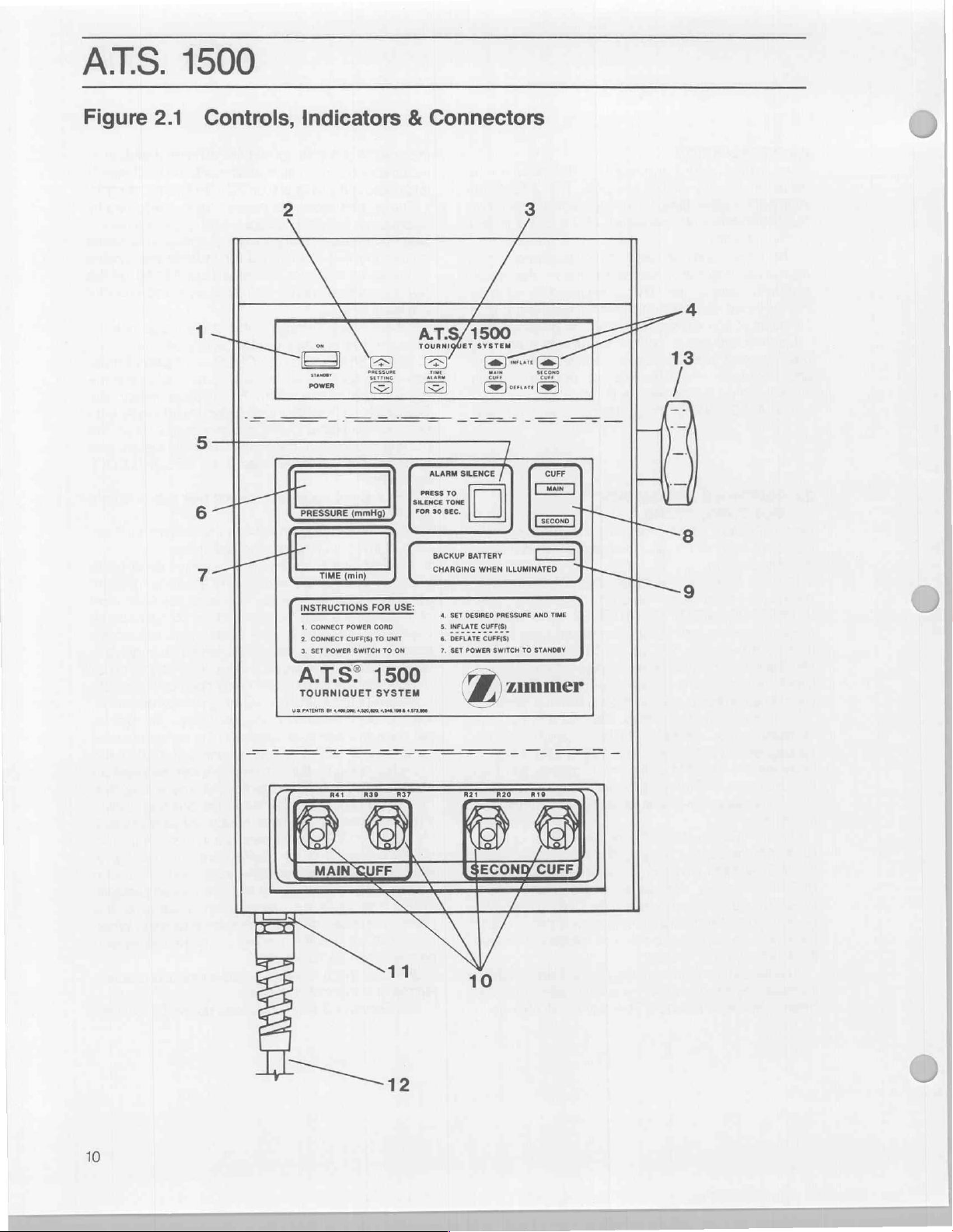
Figure
2.1
1500
Controls,
Me
i
MT
6
7
—İ
TT
Indicators & Connectors
2 3
x 7
HT
PRESSURE
厂
INSTRUCTIONS
=a
TIME
4.
CONNECT
2.
CONNECT
3.
SET
N
EA
(min)
POWER
CUFF(S)
POWER
(mmHg)
FOR
CORD
TO
SWITCH
(
‘SILENCE
|”
USE:
UNIT
TO
ON
AT.
PRESS
“
ALARM
SILENCE
TO
TONE
SEC.
30
BACKUP
CHARGING
4.
SET
5.
INFLATE
6.
DEFLATE
7.
SET
a
500
ma
/
圖
BATTERY
WHEN
DESIRED
PRESSURE
CUFF(S)_
CUFF(S)
POWER
SWITCH
t
ILLUMINATED.
CUFF
(esses)
[==
AND
TIME
TO
STANDBY
TA
+
—
=
H
\
|
|
/
L
>
|
8
440000:
432000,
2
4346100
CUFF
m
US.
PATENTE
DV
01
MAIN
P
437.00
VA
ECOND/
0
ammer
CUFF
/
10
Page 13
7.
TIME
DISPLAY — During
touch-switches
the
inflation
to a
maximum
may
be
touch-switches
above.
If
setting,
See
Section
abnormal
See
Section
8.
CUFF
active.
Lights
indicate
9,
BACKUP
when
the
higher
illuminated
nected
battery
for
being
time
of
the
of
240
viewed
the
the
on
are
operated
inflation
display
2.8
conditions.
4.3.4
LIGHTS — Indicates
flash
which
cuffs
BATTERY
backup
level
charging
when
the
more
than a few
in
the
unit,
receiving a charge.
intervals,
charged
transition
also
be
up
or
between
off
while
to a few
the
battery
the
recover a severely
Section
10.
cuff(s).
11.
against
replaced
12.
unit
13.
unit
2.5
1.
tion,
source
nameplate
2.
connectors.
3.
unit
described
completion
to
CAUTION:
that
during
declare
3.2.1
for
battery
CUFF
CONNECTORS
PRIMARY
POWER
when
POLE
on
an
SINGLE
With
the
connect
that
LINE
internal
only
with
CORD — Supplies
connected
CLAMP — Adjustable
IV.
pole.
CUFF
ON/STANDBY
the
is
compatible
of
the
Connect a dual
Set
the
ON/STANDBY
will
execute a self-check
in
Section
of
the
use.
Special
if
either
cuff
power-up,
it
an
abnormal
overloads.
one
power
device.
port
self-check
is
normal
depressed,
cuff(s)
minutes.
this
display
in
time
has
will
flash
for
indications
for
indications
operation,
this
in 1 min.
The
time
when
accordance
exceeded
the
current
during
during
which
when a pressure
to
check.
LIGHT — This
battery
is
states.
power
charging
The
cord
has
seconds
or
if
the
battery
The
light
may
go
minutes,
charging
trickle
discharged
charger
FUSE
of
to
appropriate
if
charger
states.
charger
—
Ports
—
Protects
This
the
same
primary
the
has
battery.
operation.
to
clamp
OPERATION
switch
in
the
cord
to
an
with
the
ratings
cuff
to
the
unit
switch
to
the
diagnostic
2.2
of
this
manual.
indicates
note
should
pressurized
the
A.T.S.
be
to
50
1500
start-up
with
display
will
increments
alarm
the
time
with
the
time
inflation
alarms
Calibration.
cuff
or
cuffs
alarm
occurs
light
is
illuminated
in
one
light
will
not
been
discon-
or
if
there
is
incapable
off
for
varying
battery
just
made
The
light
is
attempting
Refer
connect
fuse
type
receptacle.
power
should
and
AC
to
mount
tubing
rating.
power
STANDBY
electrical
listed
at
the
main
ON
position.
test
Successful
the
unit
is
made
of
the
mmHg
or
Tourniquet
sequence.
no
show
up
setting
alarm
item
3
alarm
time.
or
are
to
of
the
be
is
no
of
is
fully
a
will
to
to
to
line
be
to
the
posi-
power
on
the
cuff
The
as
ready
fact
more
will
It
will
assume
will
cuff
the
(depending
in
the
pitched
light.
pressure
alarm
that a surgical
adopt
the
as
the
new
inflation
excess
of
operator
tone
The
operator
set
is
cleared
higher
mode
on
whether
50
of
this
and
point
Switch.
4.
In
the
absence
preset
values
for
time
alarm
of
200
These
decrease
to
tive
applied
the
5.
The
the
the
values
pressing
For
each
the
minimum
pressure
account
normal,
operative
pated
rise
Set the
ing
the
switch
until
desired
(+)
or
decrease
Prepare
lished
procedures
may
the
PRESSURE
(—)
touch-switch
patient,
should
factors
to
an
upper
hyperthrophied,
systolic
in
systolic
desired
PRESSURE
the
desired
inflation
the
patient
precautions
offered
possible
cular
positions
niquet
area
of
inflated
wrinkles.
be
the
pared
and
as a guide
In
most
cases a tourniquet
widest
part
to
lie
between
structures
are the
thigh.
In
certain
cuff
can
proximal
the
to
hand, a sufficiently
around
Apply a leak-free
The
valve
placed
limb
so
is
positioned
and
draped
deeper
that
tissues
exsanguination
Exsanguinate
of 2 minutes
and
ATS.
procedure
of
the
set
point.
It
and
regulate
either
mmHg)
effective
such
(—)
of
susceptible
be
the
of
the
to
condition,
illuminate
should
and
readjust
by
depressing
of
operator
desired
mmHg
and
be
observed
and/or
tourniquet
pressure.
be
determined
as:
or
lower
or
pressure;
pressure
cuff
pressure
increase
setting
time
alarm
touch-switches.
in
accordance
and
cuff
of
Section 1 and
to
assist
the
limb
the
upper
arm and
cases
of
applied
the
malleoli. For
wrist.
tourniquet
stem
and
the
tubing
for
surgery.
for
surgery.
should
the
limb
limb
by
wrapping
is in
pressures
will
the
the
the
immediately
cuff
60
for
up
whether
limb;
obese;
and
(+)
is
using
manufacturer's
sensed
automatically
either
or
or
both
had
new
set
point.
unit
will
Alarm
Silence
it
if
necessary.
the
Alarm
action,
the
pressure
minutes
on
the
TIME
increase
to
1.5
seconds.
pressure
The
the
should
minimum
by
cuff
whether
the
the
maximum
during
the
by
pressing
or
decrease
reached.
the
TIME
with
the
in
this
process.
cuff
should
to
allow
as
much
cuff
and
any
nerves
to
damage.
fore-foot
around
small
cuff
tube
will
The
be
and
tourniquet
elevating
it,
starting
The
the
proximal
surgery,
the
calf
emergency
tourniquet
smoothly
connections
not
be
The
limb
viability
established
it
for a minimum
from
1500
process
sound a high
unit
and
respectively.
displays
patients
procedure.
Similarly
instructions.
following
be
kinked
and
in
each
go
into
both
cuffs
pressures
To
alert
Switch
check
the
The
Silence
adopts
inflation
by
(+)
or
be
set
effec-
taking
is
the
into
to
be
limb
is
pre-
antici-
and
hold-
(—)
touch-
set
increase
your
estab-
are
applied
tissue
as
or
vas-
optimum
third
the
tour-
or
to
the
surgery
can
be
without
at
of
should
when
is
then
pre-
of
the skin
prior
to
inflation.
the
distal
1
Page 14
ATS.
and
progressing
Esmark,
should
edge
removed
anesthesia
block
The
anatomy,
surgeon
inflated,
allow
the
operation
operating
the
certain
need
healthy
two
the
for
should
pressure
dressings.
be
are
minimum.
6.
INFLATE
cuff
clock.
cuff
within
pressure
information
7.
pressing
MAIN
will
time
if
desired.
underlying
deflation.
Martin,
come
of
the
following
is
is
then
tourniquet
age,
will
to
what
for
intermittent
cuff
for
10
the
rooms,
time
of
time
for
further
There
is
adults,
hours
should
tourniquet
about
15
be
elevated
should
Under
optimum
kept
inflated
in
place.
The
cuff
is
touch-switch.
to
the
desired
The
MAIN
activation.
15
mmHg
alarm
At
the
end
the
CUFF
show
the
clock
will
It
is
best
The
1500
to
the
or
elastic
up
approximately
tourniquet
being
administered.
and
determine
to
tourniquet
inflation,
period
tourniquet
general
about
to
allow
to
20
be
until
Postoperative
inflated
If
the
will
about
of
MAIN
light
deflation
stop.
to
remove
bandages
time
cuff.
inflation
used,
the
time
depends
absence
when
pressure,
aeration
15
minutes,
should
it
is
customary
and
so
that
agreement
one and a half
not
be
the
minutes.
about
applied
conditions,
the
by
pressing
The
pressure
CUFF
light
unit
cannot
of
setpoint
be
sounded.
possible
the
procedure,
CUFF
will
go
of
Record
the
immediately
of
tourniquet
proximal
bandage.
to
one
The
elastic
of
the
anesthetic
greatly
of
vascular
the
tourniquet
for
how
long,
of
tissue
and
to
what
be
released.
to
note
to
warn
the
he
or
she can
time.
that,
hours
exceeded
underlying
During
60
to
final
swelling
without
tissue
this
degrees,
the
incision
the
tourniquet
compression
is
the red
unit
will
pressurize
and
start
will
illuminate
pressurize
in
less
than
See
alarm
conditions.
deflate
DEFLATE
out,
the
the
touch-switch.
the
PRESSURE
cuff,
elapsed
tourniquet
cuff
part,
using
The
bandage
inch
from
bandage
cuff.
If
agent
on
the
disease.
whether
by
deflating
point
prominently
surgeon
assess
for
reasonably
is
“safe”
releasing
to
“breathe”
time,
and
with
dressings
then
kept
MAIN
the
the
inflation
to
the
30
seconds,
Section
the
and
the
inflation
cuff
and
following
removal
an
the
is
regional
or
nerve
patients
The
is
to
be
to
in
the
In
many
after
a
the
and
the
limb
steady
sterile
cuff
can
to
a
CUFF
main
time
indicate
cuff
to
a
2.8
for
cuff
by
The
display
inflation
time
any
final
should
be
noted,
be
checked.
8.
Set
tion
only
50
mmHg.
2.6
DUAL
Operation
tion
1.
Both
the
unit.
2.
The
(ie.
If
are
inflated.)
3.
During a pressure
indicates
4.
Deflation
other
5.
When
inflated,
to
insure
unit
will
to
within
inflating
tains
in
the
rate
of
causing
display
allow
6.
When
inflated,
remains
7.
When
average
has a significant
a
sustained
pressure
cuffs
inflated
inflated
quently,
below
and
the
ON/STANDBY
after
the
CUFF
of
the
(see
Section
dual
port
CUFF
both
CUFF
the
cuff(s)
of
one
cuff
is
inflating.
inflating a cuff
the
unit
that
the
stop
its
10
mm
cuff.
This
occlusion
original
the
shows
the
at
cuff,
subsequent
the
30
the
operator
deflating a cuff
the
display
inflated.
both
cuffs
of
the
pressures
leak
alarm
as
one
commences
is
within
cuff
remains
when
neither
set
point,
the
lights
will
pressure
inflation,
second
may
the
circulation
switch
pressure
display
OPERATION
unit
is
identical
2.5)
except
cuffs
are
connected
indicate
lights
are
illuminated
alarm
to
check.
cuff
will
not
with
continuously
is
within
and
of
setpoint
is
to
insure
that
all
times.
If
this
feature
cuff
to
inflation
pressure
to
view
in
the
with
shows
the
are
inflated,
sensed
leak
(as
described
(as
described
be
sounded.
when
3mm
of
set
within
10mm
cuff
pressure
average
of
the
to
the
STANDBY
indicates
to
Single
for
the
following
at
the
cuff that
the
flashing
be
permitted
the
other
check
allowable
maintain
before
there
could
be
the
returning
at
least
is a significant
cause
longer,
alarm
the
inflating
progress
the
other
pressure
the
display
in
the
in
in
section
Regulation
the
second
point
while
of
set
is
of
the
pressures
limb
less
Cuff
the
bottom
is
then
both
CUFF
while
cuff
the
original
limits.
original
one
cuff
the
perhaps
to
sound.
cuff
of
inflation.
cuff
remaining
in
the
indicates
two
cuffs.
section
cuff
the
point.
30mm
should
posi-
than
opera-
points;
of
active.
cuffs
light
the
already
cuff
The
cuff
to
the
main-
leak
inflation
even
The
so as
to
cuff
that
an
If
one
2.8),
or
2.81)
a
of
dual
to
be
initially
Subse-
or
more
sensed
12
Page 15
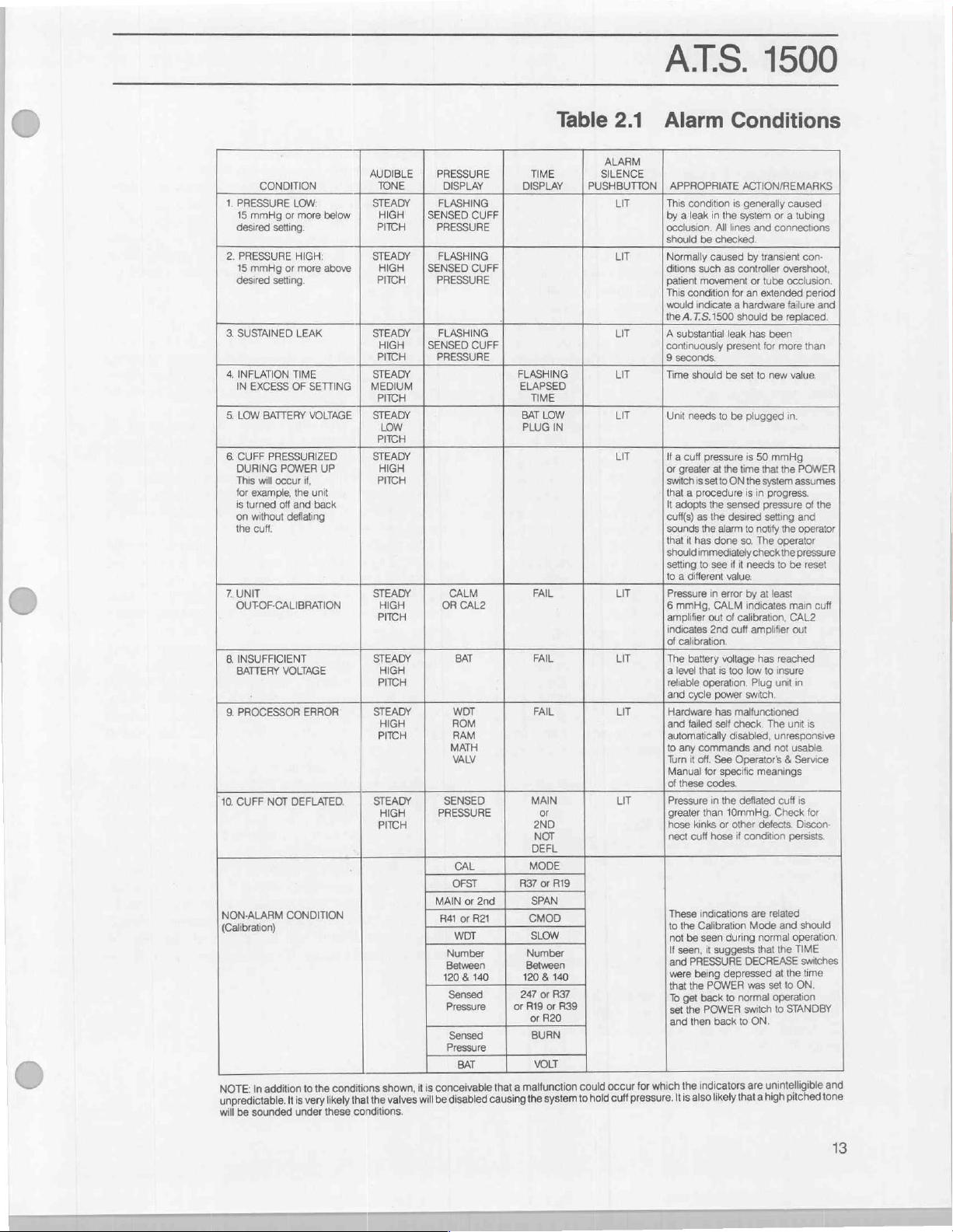
O
A.S.
CONDITION
1.
PRESSURE
15
desired
2.
PRESSURE
15
desired
3.
SUSTAINED
4,
INFLATION
IN
5.
LOW
6.
CUFF
DURING
This
for
is
turned
on
the
7.
UNIT
OUT-OF-CALIBRATION
8.
INSUFFICIENT
BATTERY
9.
PROCESSOR
10.
CUFF
NON-ALARM
(Calibration)
NOTE:
unpredictable.
will
be
LOW:
mmHg
or
more
setting.
HIGH:
mmHg
or
more
setting.
LEAK
TIME
EXCESS
OF
SETTING | MEDIUM
BATTERY VOLTAGE
PRESSURIZED
POWER
will
occur
the
off
and
deflating
VOLTAGE
NOT
DEFLATED.
CONDITION
addition
is
It
under
if,
unit
back
ERROR
to
very
example,
without
cuff.
In
sounded
the
AUDIBLE
TONE
STEADY
below
above
UP
conditions
likely
these
HIGH
PITCH
STEADY
HIGH
PITCH
STEADY
HIGH
PITCH
STEADY
PITCH
STEADY
LOW
PITCH
STEADY
HIGH
PITCH
STEADY
HIGH
PITCH
STEADY
HIGH
PITCH
STEADY
HIGH
PITCH
STEADY
HIGH
PITCH
the
that
conditions.
SENSED
SENSED
SENSED
MAIN
conceivable
is
it
shown,
valves
will
be
PRESSURE
DISPLAY DISPLAY
FLASHING
CUFF
PRESSURE
FLASHING
CUFF
PRESSURE
FLASHING
CUFF
PRESSURE
CALM
OR
CAL2
BAT
WOT
ROM
RAM
MATH
VALV
SENSED
PRESSURE
CAL
OFST
or
2nd
Balen
Rel
WOT
ος
140
&
120
Sensed
Pressure | orRi9
Sensed
Pressure
BAT
disabled
TIME
FLASHING
ELAPSED
TIME
BAT
PLUG
FAIL
FAIL
FAIL
MAIN
or greater
2ND
NOT
DEFL
MODE
R37
or
SPAN
SMOD
SLOW
ee.
120
247
or
or
BURN
VOLT
malfunction
a
that
the
causing
Table
LOW
IN
R19
140
&
R37
or
R39
R20
system
2.1
ALARM
SILENCE
PUSHBUTTON | APPROPRIATE
LIT
LIT
LIT
LIT
LIT
LIT
LIT
LIT
LIT
occur
could
cuff
hold
to
Alarm
This
condition
by a leak
in
UT
ocelusion.
should
Normally
ditions
patient
This
would
the
A
continuously
9
Time
Unit
if a cuff
or
switch
that a procedure
It
cuff(s) as
sounds
that
should
setting
to a different
Pressure
6
amplifier
indicates
of
The
a
teliable
and
Hardware
and
automatically
to
Turn
Manual
of
Pressure
hose
All
be
checked.
caused
such
movement
condition
indicate a hardware
A.
T.S.1500
substantial
seconds.
should
needs
pressure
greater
at
is
setto
adopts
the
the
the
it
has
done
immediately
to
see
in
mmHg,
CALM
out
2nd
calibration.
battery
level
that
operation.
cycle
power
has
failed
self
any
commands
it
off.
See
for
these
codes.
in
than
kinks
nect
cuff
hose
These
indications
to
the
Calibration
not
be
seen
If
seen,
it
suggests
and
PRESSURE
being
were
that
the
POWER
To
get
back
set
the
POWER
and
then
back
indicators
the
which
for
pressure.
Itis
also
likely
1500
Conditions
ACTION/REMARKS
is
generally
the
system
lines
as
controller
for
should
leak
present
be
set
to
be
the
time
ON
sensed
desired
alarm
so.
if it
value.
error
of
calibration,
cuff
voltage
is
too
malfunctioned
check.
disabled,
Operator's & Service
specific
the
deflated
10mmHg.
or
other
if
during
depressed
to
normal
to
that
caused
or a tubing
and
connections
by
transient con-
overshoot,
or
tube
occlusion.
an
extended
failure
be
replaced.
has
been
for
more
to
new
value.
plugged
in.
is
50
mmHg
that
the
the
is
to
needs
by
indicates
amplifier
low
Plug
switch.
condition
are
Mode
DECREASE
was
switch
ON.
are
POWER
system
assumes
in
progress.
pressure
setting
and
notify
the
operator
The
operator
check
the
pressure
to
be
at
least
main
CAL2
out
has
reached
to
insure
unit
in
The
unit
unresponsive
and
not
usable.
meanings
cuff
is
Check
defects.
Discon-
persists.
related
and
should
normal
operation.
that
the
TIME
switches
time
the
at
set
to
ON.
operation
to
STANDBY
unintelligible
pitched
high
a
period
and
than
of
the
reset
cuff
is
for
and
tone
13
Page 16
ATS.
in
the
individual
simultaneously.
fall
30mm
cuff
will
be
to
the low
less
below
remains
the
low
detected
low
tion
vided
The
alternately
(are)
and
before
set
excessive
the
mence
to
one
selected
be
then
cuff
until
point.
point,
recovered
not
will
below
2.7
1.
OPERATION
2.
not
time
pressure
pressure
will
be
both
control
recovered
the
other
resuming
If
both
point
system
to
be
recoverable.
in
which
recovered
the
until
the
If
both
dual
within
be
individually
set
BIER
Review
following
The
a)
The
MAIN
or
more
secured
pressure
set
more
that
individual
cuff,
to
go
30mm
cuff
given
do
not
system
until
is
cuffs
are
(as
they
leak;
will
manage
the
for
management
to
system
it
is
not
cuff
selected
recover
cuff
to
not
10mm,
point
BLOCK
Sections
and
proximal
CUFF
1500
If
point
such
to
not
hose
attempt
not
will
more
before
tubing.
distal
The
b)
SECOND
cuff
Follow
3.
institution
Remember
4.
while
the
CUFF
tubing.
cuff
the
or
requested
that
other
is
cuffs
is
thereafter,
below
cuff
than
the
will
to
go
will
not
dual
detected
might
the
The
highest
attempt
more
regulation
then
only
set
while
individual
until
provided
30mm
attention
pressure
or
more
be
secured
the
previously
30mm
continue
time
that
more
than
more
than
cuff
regulation
to
in
the
failure,
cuff
to
secure
cuff
deemed
first
cuff
pressure
under
more
than
to
than
20mm
first
again
to
not
more
than
20mm
the
cuff
brought
dual
cuff
it
or
fall
is
to
OPERATION
and
2.5
DUAL
CUFF
suggested
are
cuff
connected
connector
connected
cuff
connector
inflation
sequence
by
the
deflation
inflating.
used
to
one
cuff
point,
then
attention
is
brought
that
the
below
set
is
being
in
the
below
set
and
individual
secured
more
below
to
manage
one
(or
10mm
20mm
simultaneously.
30mm
event
of
failure,
both
to
to
be
inflated
is
sensed.
these
20mm
inflate
the
below
falls
30mm
than
10mm
resumed.
below
with
the
no
more
regulation
2.6,
OPERATION.
connections:
cuff
to
using
the
the
to
using
adopted
surgeon.
cuff
a
of
control
is
detected
the
second
is
to
10mm
secured
point.
If
during
given
secured
point,
then
cuff pro-
set
the
both)
of
them
below
set
below
set
or
more
the
onset
or
the
like)
cuffs
and
be
more
will
If
the
conditions
below
set
lower
pressure
set
point,
below
below
If
both
set
point,
lower
pressure
than
is
resumed.
SINGLE
the
red
outlined
white/red
outlined
blue
white/blue
the
by
possible
not
is
both
to
given
or
cuff
to
the
cuff
is
the
atten-
point.
cuffs
is
point
point
below
of
an
then
com-
likely
be
the
cuff
can
point,
or
set
set
are
but
10mm
CUFF
cuff
your
2.8
ALARM
There
1500
Tourniquet
alarm.
actions
actions
causes
causes
other
actions.
In
addition
it
is
conceivable
which
able.
It
causing
that a high
conditions.
Most
seconds
The
light
remain
been
corrected.
will
be
will
cause
It
is
present
the
alarm
identify
dition
alarm
associated
manner
To
minimize
caused
a
1.5
generator.
the
1.5
Under
indication
mation
displays
CONDITIONS
are a number
Those
conditions, indications
are
shown
indicated
and
should
of
alarm conditions
to
the
indications
is
very
the
system
pitched
audible
by
depressing
in
the
lit
until
the
reenabled.
the
possible
at
any
time.
conditions
the
causes
that
presents
silence
with
that
it
by
vigorous
second
delay
The
second
certain
appears
that
appears
is
unintelligible,
that a hardware
unusable.
set
removes
to
the
the
Clamp
replace
The
the
ON/STANDBY
power
valves
cuff
to
the
the
and
hold
cuff
tourniquet.
of
conditions
will
produce a visual
in
Table
are
based
only
be
used
may
the
conditions
that a malfunction
are
unintelligible
likely
that
the
to
hold
cuff
tone
will
be
alarm
tones
may
the
Alarm
Alarm
condition
At
the
Depressing
alarm
tone
for
more
In
in
of
the
switch
multiple
does
for
nuisance
Silence
that
the
pushbutton
that
end
of
the
the
to
be
than
one
event,
sequence.
alarms
most
danger
will
silence
alarm
single
pressure
movement
has
been
pressure
period.
conditions,
failure
appropriate
in
display
the
TIME
in
the
the
has
occurred
action
operator
switch
from
the
internal
pump
will
cease
pressure
lines
with
FAIL
(in
hemostats
for
which
and/or
and
appropriate
2.1.
The
appropriate
on
the
most
as a guide.
indicate a need
shown
valves
pressure.
sounded
could
and
will
It
be
silenced
Silence
in
be
under
pushbutton.
will
created
the
silence period,
Alarm
Silence
silenced
alarm
the
The
and
conditions
alarm
of
designed
will
such
display
TIME
again.
condition
unit
will
operator
act
on
first.
Note
the
audible
in
conditions.
alarms
the
patient's
that
into
still
flash
as
when a FAIL
or
and
PRESSURE
should
rendering
in
such
an
to
STANDBY.
circuitry,
the
conditions
all
which
absence
or
should
the
can
the
A.
T.S.
audible
probable
Other
for
Table
2.1,
occur
for
unpredict-
disabled
is
also
likely
these
for
normally
alarm
has
tones
switch
to
announce
should
the
con-
that
the
tones
the
same
can
limbs,
the
tone
during
the
infor-
conclude
the
unit
event
is
Since
this
commands
cause
of
leaks).
like
and
only
30
be
be
to
be
14
Page 17
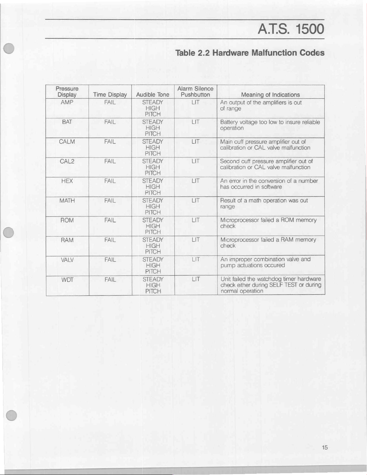
Pressure
Display Time
AMP
BAT
CALM
CAL2
HEX
MATH
ROM
RAM
VALV
WDT
Display | Audible Tone
FAIL
FAIL
FAIL
FAIL
FAIL
FAIL
FAIL
FAIL
FAIL
FAIL
STEADY
HIGH
PITCH
STEADY
HIGH
PITCH
STEADY
HIGH
PITCH
STEADY
HIGH
PITCH
STEADY
HIGH
PITCH
STEADY
HIGH
PITCH
STEADY
HIGH
PITCH
STEADY
HIGH
PITCH
STEADY
HIGH
PITCH
STEADY
HIGH
PITCH
Table
Alarm
2.2
Silence
Pushbutton
LIT
LIT
LIT
LIT
LIT
LIT
LIT
LIT
LIT
LIT
Hardware
An
of
Battery
operation
Main
calibration
Second
calibration
An
has
Result
range
Microprocessor
check
Microprocessor
check
An
pump
Unit
check
normal
Meaning
output
range
voltage
cuff
cuff
error
in
occurred
of a math
improper
actuations
failed
either
operation
ATS.
Malfunction
of
Indications
of
the
amplifiers
too
low
to
pressure
or
or
the
the
amplifier
CAL
valve
pressure
CAL
in
combination
watchdog
during
amplifier
valve
conversion
software
operation
failed a ROM
failed a RAM
occured
SELF
1500
Codes
is
out
insure
reliable
out
of a
was
memory
memory
valve
timer
TEST
of
out
of
number
out
and
hardware
or
during
malfunction
malfunction
O
Page 18
ATS.
reset
by
setting
In
the
event
that a FAIL
sient
condition,
operation
STANDBY
the
The
identified
delineated
2.8.1
A
pressure
cuff
by
and
special
CAUTION
definitions
in
in
PRESSURE
is
more
alarm
than
1500
the
ON/STANDBY
shutdown
it
may
be
possible
first
setting
then
for
conditions 7 through 9 of
Table
15
setting
note
the
2.2.
ALARMS
will
occur
mmHg
the
in
hardware
switch
was
to
ON/STANDBY
it
back
to
2.53
for
when
then
from
the
caused
resume
ON.
abnormal
failure
pressure
to
STANDBY.
by
tran-
normal
switch
Please
read
startup.
messages
Table
21
pressure
setpoint.
to
are
in
It
substantial
continual
a
pin
This
a
substantial
when
than 9 seconds.
displayed
setpoint,
a
detected
be
is
also
hole
type
cuff
to
this
checked
possible
but
which
pumping.
in a cuff
of
leak
hold
pressure.
leak
is
type
of
If a pressure
pressure
then
this
and
all
for
leaks.
for a cuff
the
This
bladder,
could
present, a pressure
leak
is
is
not
type
cuffs
and
to
have a leak
unit
can
compensate
type
of
leak
or a loose
progress
To
continuously
of
into a total
alert
the
alarm
more
than
substantial
pneumatic
could
be
pneumatic
failure
operator
alarm
is
declared
present
occurs,
for
15
mmHg
leak
has
fittings
that
for
by
due
fitting.
that
more
and
the
from
been
should
is
to
of
a
16
Page 19
O
O
A.T.S.
3.1
BLOCK
Refer
The
A.T.S.
controlled
takes
verter,
generate
displays,
pressure.
inflation,
tourniquet
The main
pump
inflation
closed
and
V6
atmosphere
block
(no
power)
cause power
failure
cease
internal
The
converter
digitized
sor,
along
pump,
dition
checked.
tage
when
alarm
loss
of
The
monitors a timing
sor.
Should
problem
the
Watch
and
the
microprocessor.
the
interrupt, a failure
panel
DIAGRAM
to
Figure
1500
automatic
inputs
from
and
the
memory
commands
alarm
The
pump
deflation,
cuffs
and
via
valves
of
the
cuffs.
and
valves
connect
periodically
diagram
(Figure
conditions.
to
fail
mode,
the
and
they
leaks.
pressure
pressure
to
of
when
AC
Watch
valves
displays
transducers
via
excitation
with a velocity
regulate
the
+12V
This
voltage
AC
power
the
power
Dog
this
signal
with
either
Dog
Timer
and
and
1500
3.1
Tourniquet
tourniquet.
various
to
circuitry)
and
sensing,
and
their
second
V1
and
V3.
For
deflation
V2
and
the
pressure
for
3.1)
Should a condition
or
should
power
to
will
go
and
signals
the
pressure
power
represents
is
not
battery
or
during
voltage
Timer
signal
generated
become
the
microprocessor
circuit
attempts a hardware
If
the
microprocessor
message
an
alarm
is a microprocessor
switches,
and
uses
the
outputs
in
order
the
six
and
pressure
cuffs
are
These
V4 are
calibration.
shows
the
the
valves
into a position
are
amplification
are
used
feedback
in
supply
present.
becomes
patient
is a hardware
abnormal,
cuts
is
tone
THEORY
OPERATION
TOURNIQUET
The
microprocessor
the
A/D
this
information
(valves,
to
regulate
valves
calibration
valves
of
opened.
transducers
all
unit
connected
by
the
is
the
by
off
displayed
is
control
transducers.
connected
are
the
cuffs,
Please
valves
enter a hardware
and
the
that
to
circuitry.
the
microproces-
signal
cuff(s).
also
periodically
true
battery
The
unit
low
transport.
circuit
the
microproces-
indicating
or
the
power
to
interrupt
is
able
on
emitted.
SECTION
con-
to
pump,
cuff
the
of
the
two
to
the
open
for
they
are
Valves
V5
to
the
note
the
in
their
off
occur
to
pump
will
prevents
the
A/D
The
from
the
The
con-
vol-
can
thus
during
a
that
a
software,
the
pump
of
the
to
act
on
the
front
30
3.2
DETAILED
The
following
of
the
basis.
the
Power
Figures
3.2.1
Primary
cord
resettable
windings
nected
fault
condition
which
the
thermal
from
With a nominal
the
transformer
mately
filtered
+22.2
section
TP2
is
battery
An
produce
resistive
output
the
output
are
protection
OF
CIRCUIT
is a detailed
tourniguet's
The
text
is
supplemented
Supply
4.9
and
4.10
Power
Refer
with
the
Supply/Battery
to
Figure
AC power
fault
protection
thermal
of
the
power
between
terminals 1 and
that
would
degrade
fuse
would
unit.
have
174
VRMS
by
capacitor
VDC
at
TP2.
will
vary
with
used
as
an
charging
circuit.
adjustable
an
output
divider
voltage.
comprised
Capacitors
and
adjustment
diodes
primary
SYSTEM
DESCRIPTION
description
electronics
and
respectively.
49
is
supplied
fuse
would
the
open
an
which
C3
Note
load
input
to
voltage
voltage
for
on a circuit
by
the
the
Logic
Charger
to
the
provided
is
encapsulated
transformer
2.
result
in
winding
insulation
removing
voltage,
output
is
to
that
terminals 5 and
voltage
rectified
by
produce
the
voltages
conditions.
the
12
volt
regulator
of
+12
of
R1,
R2,
C1
and
C2
pins
while
the
voltage
of
the
operation
by
schematics
Board
found
(A2)
unit
via
the
by
A4F1. A non-
between
A3T1,
and
In
the
event
temperatures
of
the
transformer,
primary
of
approxi-
bridge
CR1 and
approximately
listed
The
voltage
regulator
(VR1)
is
used
VDC
at
TP1.
and
RS
insure
stability
CR5
and
regulator.
circuit
of
in
power
the
con-
of
a
power
6 of
in
this
at
and
the
to
The
sets
the
at
CR6
17
Page 20
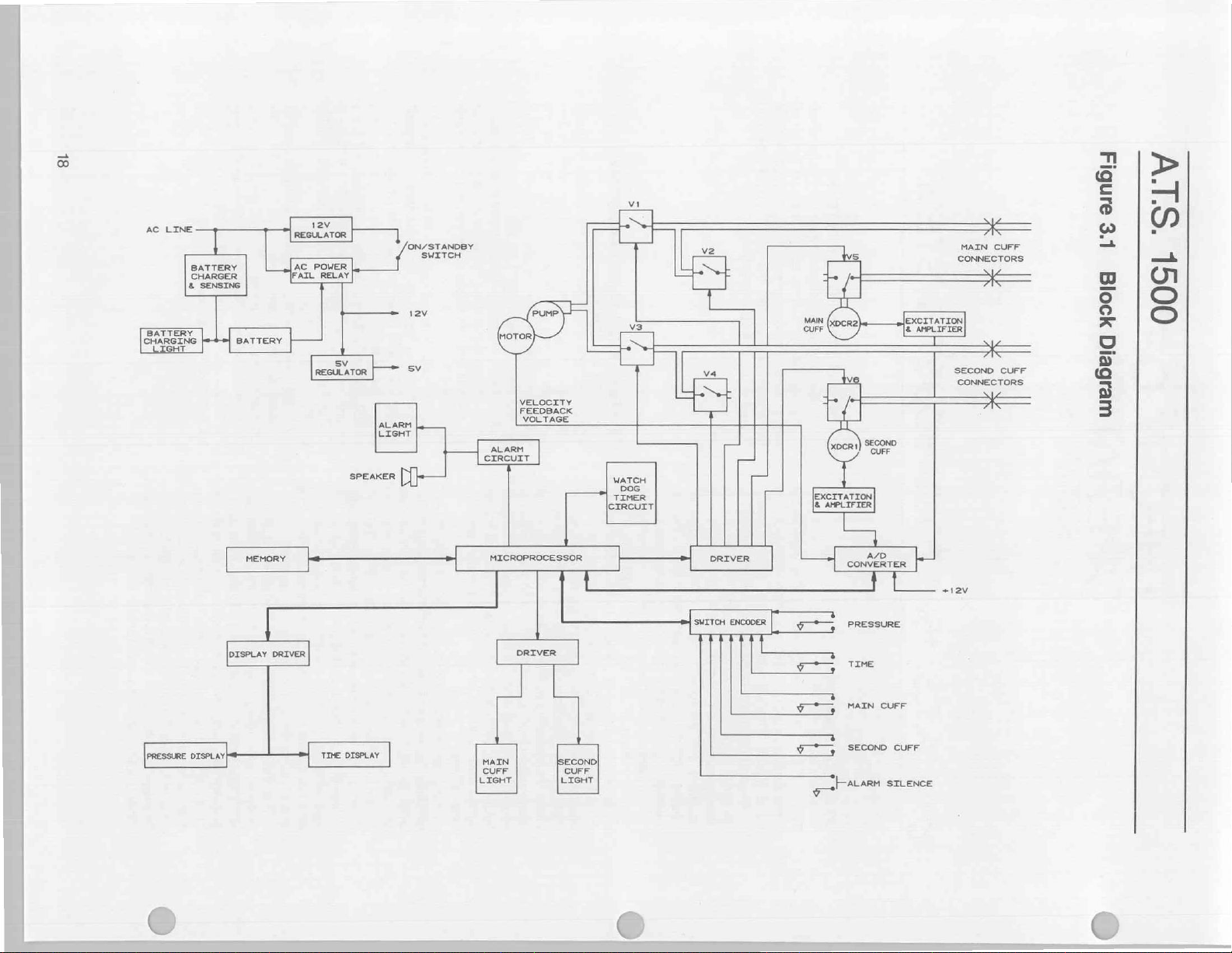
8L
AC
LINE
BATTERY
CHARGING
PRESSURE
BATTERY
CHARGER
&
SENSING
DISPLAY|
|
DISPLAY
eee
DRIVER
12V
REGULATOR
AC
POWER
İFATL
RELAY
그
ee
|
"i
sv
거우!
SPEAKER
一
ALARM
LIGHT
一
一
'ON/STANDBY
SWITCH
sv
出-
一
一
一
VELOCITY
FEEDBACK
VOLTAGE
ALARM
LerRcurr
MICROPROCESSOR
DRIVER
MAIN
CUFF CUFF
LIGHT
PRO!
し レレ
LIGHT
t
COND}
WATCH
TIMER
[CIRCUIT
トーー-
ーー
vi
—
DOG
=
er
SWITCH
ENCODER
=
(+
|
меч
>
L,
qo
vw,
я
ver
ý
*,
>
A/D
CONVERTER
pressure
TIME
MAIN CUFF
SECOND
CUFF
上
ALARM
SILENCE
MAIN
CONNECTORS
SECOND
CONNECTORS
av
|
x
т
CUFF
し
À
CUFF
aunbig
‘SIV
L'g
yo0/q
weibeiq
0091
Page 21
The
voltage
charging
battery
sealed
charger
lead
Tourniquet.
at
pins 3 and
insures
to
stability
sense
Transistor
voltage and
is a pass
discharging
for
sensing
resistive
R19,
and
levels
used
determines
present.
the
circuit
trickle
charge
A2U2-11
battery.
is a bulk
0.5
Amps
battery
the
voltage
circuit
imately
Here
the
voltage
of
through
50
mA,
float
stage.
charging
life.
A2U1
from
circuit.
Integrated
designed
acid
The
voltage
battery
5. A 22
of
the
the
charging
Q1
is a pass
current
diode
when
applied
used
AC power
when a battery
divider
R6
sets
by
string
the
the
circuit.
if a battery
If
not
(a
dead
does
not
of
up
to
attempt
If a battery
charge
DC
state
to
the
is
through
senses
+14.2
circuit
+14.9
R7.
the
voltage
and
that
VDC,
provides
VDC
When
the
circuit
enters
Here
the
of
associated
TP2
IC.
voltage
output
to
to
sensed,
where
battery
the
while
current
battery
+13.8
amplifier/comparator
BATTERY
age
mode
CALIBRATION
ature
A2C12
The
through
protects
reversal
voltage
where
is
lost.
The
(power
low
tery
voltage
not
mode
battery
deep
life
CHARGING
sensed
across
adjustment
compensation
stabilizes
battery
it
unit
cord
battery
voltage
goes
be
insured
when
to
discharge
also
is
is
fuse
Fi
charging
the
while
connecting
fed
also
is
is
available
may
disconnected)
alarm
is
below
so
+105
accept
degraded
A2CR9.
for
Section.
for
the
battery
connected
which
circuit
to
to
power
be
operated
be
will
than
less
+10.5
the
unit
VDC
charge
a
low
and
is
also
used
by
circuit
U2
specifically
found
from
TP2
uP
tantalum
Precision
current
going
device
to
the
to
prevent
is
not
is
receiving a charge.
comprised
different
Upon
of
battery
9mA
or
any
will
for
in
the
is
fed
capacitor
resistor
into
for
controlling
battery.
the
present
of
R15,
voltage and
power
at
least
no
battery
voltage,
be
supplied
recover a deeply
the
first
charging
the
circuit
while
sensing
pins
12
and
13
the
battery
second
the
sensing
the
VDC
circuit
light
the
A2CR13
the
voltage
stage
battery
with a constant
the
drops
to
third
stage
is
held
at
to
optimize
circuitry
are a differential
used
depending
A2R12
first
stage
provides
CHARGING
approximately
to
is a common-
charger.
to
the
charging
in
conjunction
from
the battery.
terminals
the
for
generated
+115
VDC,
goes
reached.
is
will
battery
continued
by
with
accidental
an
and
5
tourniquet
on
battery
least
at
whenever
VDC.
reliable
into a BATTERY
The
adversely
be
temperature.
deep
the
battery
implements
the
type
A.7.S.
1500
into
the
chip
(C4)
R7
is
used
the
battery.
the
Diode
CRY
battery
as
from
well
The
R16, R17,
current
up
the circuit
+11.0
VDC
present)
however
from
discharged
stage
provides
of
current
its
the
scaled
U2.
When
is
approx-
is
reached.
drawn
which
ideal
up
is
float
standby
control
on the
of
A2U1;
light
diode
The
of
8
if
power
15
the
If
operation
ability
the
volt-
see
temper-
circuit.
circuit
CR10
polarity
battery
relay
AC
power
alone
minutes.
bat-
the
battery
can-
FAIL
of
affected
Battery
discharge
a
of
as
is
a
to
a
Ki
A
the
by
cycles,
discharged
power
the
recommended
and 8 of
present.
filtered
at
the
voltage,
voltage
terminals 7 and 8 of
diodes
whenever
+12
tively.
voltage
tects
the
E14
+12
the
available
K2.
K2
is
and
Capacitors
CR11
its
operations,
VALVENA
present
further
filtered
determines
DRIVE
amplifier
the
provides
high
state.
to
operate
unit
without a battery
When
AC
the
transformer
This
by
capacitor
TP3.
Resistor
capacitor
Vunres
is
applied
CR3 & CR4
AC power
VDC
and
When
there
(Vem)
the
coil
Moving
the
voltages
and
E9
respectively.
voltage
main
logic
at
terminal 7 and
The
voltage
and
to
the
preset
at
+5
is
available
C10 and
is a protection
When
the
self
testing
(E11)
at
E8
filtered by
voltage
that
voltage
(Q2,
DC
motor
current
temperature
Because
the
unit
that
the
power
is
voltage
C7
R26
voltage
for
is
approximately
to
terminal 7 of
the
and
is
Vunres
is
is
no
is
present
of
the
relay
power
switch
present
is
A.T.S.
at
further
board
via
Vunses
voltage
VDC
to
regulator
which
the
diode.
1500
and
is
relay
K2
filtered
low.
(VALVES)
R25
is
called
the
pump
at
E18
Q3,
and
connected
limiting
comprise a resistive
(Vac)
protects
voltages
12V
current
assembly
IDLE,
vibrate
used
to
the
motor
of
the
Ret
protects
during
has
and
RUN.
(oscillate).
determine
drive
motor.
the
the
discharge
three
During
This
pump.
The
voltages
the
A2
power
main
logic
49
lists
voltage/signal
each
board
the
and
signals
supply
through a wire/cable
pin
numbers
goes
ΑΤ.5.
storage,
the
battery
if
AC
power
is
not
recommended.
battery
applied
have
is
is a bleed
safe
transformer
fed
present,
present
AC power
at
E6
is
C11
ready
This
and
associated
divider
The
relay
modes
board
be
replaced
to
the
approximately
rectified
to
by
produce a voltage
off
servicing.
relay
to
the
coil
relay
at
E7
present,
E6
and
E7.
during
power
to
the
ON
and
E7
to
With
AC
power
by
C6
E10.
The
+12
one
side
connected
VR2.
can
be
main
logic
insure
stability
Tourniquet
to
commence
is
switched
allows
and
allows
capacitors
VMOTOR.
causes
to
and
must
operate,
the
the
pump.
resistors
Whenever
resistors)
for a feedback
motor
speed.
amplifier
from
resistor
contacts
of
A2C8,
of
idle
state
is
normal
coming
are
connected
of
the
cable
to.
1500
and
storage
provides
fails,
operation
annually.
unit,
terminals
12.0
bridge
+15.1
is
and
of
The
measured
operation:
condition
from
CR2
resistor
At
nominal
VDC.
K1.
The
also
rectified
of
relay
K1.
K1
switches
and
E6
the
Diode
CR7
down.
position
be
connected
present,
is
available
voltage
the
coil
to
terminal
output
board
and
has
completed
by
bringing
+12
VDC
Vunres
C8 8 C9.
the
emitter
Resistor
R22 & R23
Diode
the
inductive
from
A2K2-8
by
limiting
C9.
The
the
pump
and
harness.
connector
to
AC
respec-
battery
of
via
the
follower
to
voltage
going
to
in
a
the
of
It
is
7
VRMS
and
Vunres
lower
line
This
from
by
Thus,
and
pro-
allows
to
the
to
is
also
relay
10
of
of
VR2
at
TP5
E16.
diode
normal
to
be
to
be
This
unit
PUMP
power
A3R1
CR12
to
peak
pump
OFF,
will
for
the
to
the
A1
Figure
that
49
Page 22

A.T.S.
3.2.2
Microprocessor
The
microprocessor
Tourniquet
uP
receives
up,
capacitor
proper
reset
high
for
3.58
MHz
and
C10
and
19.
The
configured
Inthe
A.T.S.
is
used
to
Port 3 (pins
inputs
Ports 0 and 2 are
address/data
transferring
input
(U15).
lines
and
bus
which
latched
there
and
instructions
To
(pins
then
(please
causes
memory
present
until
returns
able
line
program
19
of
U15
later.
The
or
write
A
data read
ferent
from a program
First,
the
This
is
to
pret
the
Secondly,
address
(pin
line
the
data
Figure
see
from
tions
when
an
10
Pin
display
the
is
11
Pin
12
Pin
WDTFAIL
drive
pump
WDT
circuit.
3.2.3
Control
control
The
1500
is
an
bypassed
C12
by
causing
at
least
24
quarts
crystal
to
implement
uP
has
in
different
1500
directly
10
through
outputs
bus
data.
The
do
this
the
30
and
places
see
Figure
the
into
an 8 bit
chip.
The upper 5 bits
on
pins
21
after
the
PSEN
to a logic
of
the
EPROM
instruction
and
is
entire
process
operation
or
write
uP
does
insure
that
address
causes
16)
is
used
is
as a request
every
either
the
of
transferred
Thus
3.2).
EPROM
the
external
uP
the
of
address
as
interrupt
an
goes
line
circuitry.
Line
line
And
Memory
(uP)
used
80C31
and
with
+5
VDC
an
internal
the
voltage
oscillator
(X2)
along
the
four
8 bit
ways
for
Tourniquet
control
used
from
29
the
the
17)
which
will
to
implement a multiplexed
for
outputting
primary
the
program
uP
places
respectively)
address
3.2).
lower 8 bits
latch
that
through
instruction
25
low
(pin
is
then
output
read
by
the
is
repeated
to
an
external
from
an
memory
not
pulse
the
EPROM
data
read
RD
the
low
go
to
uP
on
the
constantly
pP
the
interrupting
read
or
write
to
used
is
writing
when
for
input
an
line
Pin
low.
and
14
Pins
Decoder
decoder
is
in
the
A.T.S.
external
periods.
uP
ports
different
port 1 (pins 1 through
valves
is
used
memory.
at
pin 40.
resistor
at
with
oscillator
be
At
pin 9 to
The
unit
capacitors
at
which
applications.
and
cuff
for a variety
discussed
power
insure
remain
uses
pins
can
lights.
addresses
purpose
The
is
of
is
bringing
uP
the
for a program
or
address/data
output
the
that
13
of
the
memory
the
ALE
and
in a logic
on
the
address/data
ALE
line
of
the
address
internal
readin.
of
the
the
uP
to
address
andare
The
the
22
of
U15)
on
pins
one
machine
until a data read
address
external
fetch
line
during
is
implemented
in
ALE
(U15)
write
(pin
the
needed.
the
the
to
alarm
senses
the
is
are
15
address
several
or
PSEN
does
to
an
17)
the
fetches
process
highest
display
silence
output
outputs
bus
EPROM
PSEN
high
goes
the
87C64
uP
output
low.
11
through
occurs.
not
instruction.
external
the
or
time
bus
(please
instruc-
switch.
when
for
for
using
1500
The
a
a
C9
18
be
8)
of
later.
and
is
to
state
low
to
be
are
held
then
en-
The
state
is
dif-
ways.
lines.
inter-
WR
when
only
of
bit
chip.
the
the
the
a
74HC259
AND
from
address/data
strobe
intrepreting
memory.
either
address
of
U8)
determine
of
the
address
would
and
address
latch
RD
address/data
The
by
The
line
the
(U3),
control
The
that
outputs
external
line
display
select
(address
(address
Receiving
Hex),
external
3.2.4
The
tones
of
the
996
other
inverter
signal
other
Outputs
generating
MHz)
(U16).
WDT/Sound
KHz)
the
output
15
Output
addressable
gate
U9.
an
external
line
is
held
the
With
the
RD
to
be
low.
The
which
address
of
B000
cause
the
cause
that
corresponds
will
use
this
signal,
to
enable
bus.
data
present
the
uP
which
end
of
the
goes
low
as
PSEN
line
the
output
line
lasts
process
the
signal
for
WR
line
data
location
for
chip
(address
(address
DOOO
5000
data
and
the
read
Sound
sound
Hz,
for
various
tones
488
Generator
generator
used
Hz,
frequencies
from
can
be
frequencies
Q10
their
is
the
clock
Output
is
used
by
input
clock.
frequencies.
Hz
respectively)
Q7
(244
When
lines
PSEN
or
latched
is
from
A/D
operations.
U11
measured
(996
A1
circuit
latch
the
uP
address,
ADO
high.
This
address
high,
WR
line
into
top
three
output
of
acts
as
the
Hex
(1011
top
three
output
control
external
part
connected
for
that
Hex)
from
respective
the
Hz)
to
to
the
signal,
the
outputting
on
the
then
brings
read
of a read from
is
cleared.
only a portion
an
external
goes
low
the
uP
using
the
location.
3000
7000
Hex),
Hex),
and
are
all
the
converter
is
alarm
conditions.
by
the
and
244
a 2
MHz
and
R12,
by
the
Hz)
and
signal
(500
KHz)
(U3).
second
This
second
Outputs
are
is
used
(U8)
and
one
quarter
wants
to
write
to
the
address
through
prevents
as a request
and
the
will
go
low.
U8
by
bringing
bits
of
U8
will
data.
0000
bits
(101)
be a logic 1 (high).
switch
in
combination
address/data
the
occurs
to
pin 15
Thus
write
and
the
which
WR
line
Outputting
Hex),
A/D
the
external
switch
latch
(address
used
to
A.T.S.
1500
Hz.
To
generate
crystal
R13,
at
TP1.
It
frequency
Q11
(488
alarm
used
by
is
the
Lastly,
frequency
divider
Q9
and
used
by
directly
is
output
AD15.
The
the
EPROM
for
address
This
causes
EN
the
16
bit
be
active
and
Thus
outputting
0000 0000
to
select
latch.
The
of
its
data
bus
RD
line
high
when
the
EPROM.
of
the
switch
each
strobing
of a
machine
is
the
same
address/data
is
latched
and
the
data
the
A/D
conversion
alarm
tone
write
operations.
(address
9000
produce
The
frequencies
Tourniquet
these
(X1)
is
driven
C7,
and
is
divided
divider
Hz)
are
tones.
Output
the
A/D
clock
signal
output
divider
generates
Q11
(61
the
WDT
as
an
alarm
program
available,
address
output
the
Hex)
C8.
converter
O4
of
or
read
on
PSEN
from
the
(pin
14
bit
12
an
Binary)
5
This
switch
with
the
on
the
is
read
again.
PSEN
Since
latch
of
a
cycle.
except
bus
into
an
control
to
the
channel
begin
circuit
B000
are
audible
are
and
by
an
This
into
five
US.
used
for
O0
(1
for
the
(62.5
(U4)
as
3
Hz
and
circuit.
tone.
20
Page 23

INSTRUCTION
FETCH
EXTERNAL
DATA
READ
MACHINE
STATES
XTAL
ALE
PSEN
P2
PI
2
e
sı
al!
αι
s2
ο
LOW
ADDRESS
μα
HIGH
MACHINE
Ss
ADDRESS
NsraucrioN
CYCLE
IN
1
54
|
ss
|
Se
si
s2
MACHINE
sa
CYCLE
s4
2
35 Se
aunbi-j
|
2“
|
HIGH
>=
Low
ADDRESS
HIGH
ADDRESS
FOR
EXTERNAL
READ
OR
WRITE
DAYAN.
>.
ADDRESS
HIGH
ADDRESS
LOW
ADDRESS,
FOR
FOF
ossaooldololN
6uluull
SIV
區
uugJ6eld
00SE
Page 24

ATS.
The
WDT/Sound
erasable
cuit
as
inputs
address
outputs
996
respectively.
the
nected
alarm
other
current
be
R3
speaker
open
information
tone,
5000
the
signal
into
address/data
another
to
the pP.
alarm
temporarily
3.2.5
The primary
to
detects
causes
low
removing
cause
output a 996
sage
The
mSec.
nal
by
in
soon
allowed
mum
the
well
EPLD
programmable
receives
ground
Hz
to
its
present
are
at
binary
the
and
output
thus
The
open
collector
to
the
light
and
terminals.
at
the
selected
emitted
and
The
SOUND
sound
The
and
R4
limit
while
collector
WDT/Sound
from
the
uP
writes
Hex.
This
line
from
U11
U12
from
bus.
write
until
+5
VDC
silence
silenced.
Watch
resistor
to
it
light
Dog
function
detect timing
an
error,
the
interrupt
and
the
valve
+12
of
the
timing
Hz
on
the
front
The
basic
operation
software
At
the
has
beginning
emanates
this
signal.
the
WDT
such
or
too
late
between
period
is
The
WDT
is
circuit.
sound
latched
as
different
use
1500
circuit
three
+5
at
ground,
address
output
alarm
speaker
When
the
the
driver.
U12 a four
the
causes
high.
pin 8 and
the
The
it
occurs,
is
deliberately
output
to
errors
the
enable
VDC
alarm
panel
one
from
There
that
the
pulses
33
implemented
This
registers.
is
logic
alarm
VDC
and
(pin
20
pins
16,
+5
(pin
drivers
circuit
light
have
an
alarm
frequency
alarm
power
R51
tone
information
the
This
signal
the
three
output
thus
is
used
in
and
light
insures
receives
control
least
indicate
Timer
of
the
in
WDTFAIL
line
at
pin
line
from
the
error
is
tone
displays.
of
the
main
of
pin
14
of
is a timing
if
the
WDT
fails.
is
mSEC.
chip
clocks,
implemented’
device
(EPLD).
tone
frequencies
connects
of
U3)
depending
17,
and
18.
VDC,
244
000,
001,
010,
20)
is
connected
U1
which
the
speaker.
+12
VDC
applied
tone
is
output,
causing
to
illuminate.
dissipated
bit
latch.
tone
of
U12
an
turned
to
the
Watch
the
line
12
(ENA)
pump
not
and
WDT
loop
every
the
by
proper
the
To
output
to
external
line
decoder
is
AND'ed
information
significant
remains
alarm
tone
off
brightly
alarm
Dog
uP
(U14).
is
latched
of
the
uP
to
and
too
severe,
display a help
is
relatively
that
is
begun
loop, a WDTSTB
uP.
The
window
WDTSTB
40
in
contains
Because
The
mSEC.,
the
same
the
pulse
maximum
decoding
the
signal
in
U3,
The
as
well
one
of
these
on
The
possible
Hz,
488
Hz, &
in
011, &
turn
to
one
is
con-
100
Both
to
their
U1
sinks
the
tone
Resistors
the
light
and
turn
on
of
sound
address
an
alarm
location
to
pulse
with
the
WR
is
latched
bits
of
constant
will
or
changed
until
continue
illuminate
tone
has
been
Timer
(WDT)
If
the
WOT
low
which
to
be
pulled
be
latched
valves.
the
If
unit
mes-
simple.
every
WDT
is
reset
implemented
occurs
period
mini-
the
and
EPLD
(U3).
logic
and
uP
syn-
first
is
an
cir-
the
of
the
to
the
the
by
the
is
low
the
will
37
sig-
too
as
as
the
chronized
and
uSec.
Capacitor C5
WDTSTB
were
tor
WDISTB
the
Thus
Zero
The
follows
chronized
generated.
and
time,
whose
and
divider
and
until
causes
until a STB
low
also.
occurs
Q2
of
the
high.
further
rupts
brought
removing
causes
tion
is
disabled.
In
ment
after
up,
nal,
WDISTB
WDT
have
WDTENA
enable
latching
3.2.6
The
segment,
used
to
the
SURE
cathode
play,
to
13
(see
negative
pulse
to
fail
in
R14
limits
pulse
frequency
all
WDT
point.
timing
(please
by
The
Q2
which
the
WDTSTB
outputs
J2
of
the
then
J2
are
present.
J1
has
internal
pulse
to
high
transition
In
part A of
at
its
are
all
reset.
timing
This
causes
STB
pulses
the
processor,
low,
power
the
unit
where
the
order
to
the
permanent
it
senses a logic
but
before
the
uP
tests
line
passes
been
line
line
the
Displays
displays
high
to
convey
operator.
display
drive,
is
about
the
500
KHz
Figure
the
3.3).
pulse
and
pull
eventually
middle
the
current
is
inverted
divider
timing
window
see
Figure
the
EPLD
STB
signal
are
internal
that
up
of
U4
relationships
in
the
and
pulse
Q9
and
Q11
EPLD
(Pins
commences
Signal
gone
high.
register
normal
In
window
and
to
valves
test
Q1
resets
it.
of
J2
Figure
3.4
37
mSec
part B the
and
the
WDTFAIL
are
ignored.
the
the
WDT
from
the
fail
in a nonrecoverable
seal
the
WDT,
latching
low
enabling
and
all
sucessfully
low.
high
WDTFAIL
(I1
efficiency
while
supplied
190
the relay
the
WDT
looking
of
the
tests,
completed,
The
and
will
and
through
data,
calibration,
11
and
12
13
and
mA
per
to
clock
entering
The
WDTSTB
can
be
observed
resistor
outputting
going
by
at
goes
U11
the
EPLD
R10
high
into
and
same
is
pin 5 of
the
time
begin
implemented
3.4); A WDTSTB
the
internal
is
used
to
reset
to
the
EPLD.
resets
frequency
are
connected
11
and
2).
to
count
and
J2
is
ignored
When
Ji
does
to
go
high
After
Q1
goes
will
cause
Q2
it
is
seen
that a STB
interval
STB
both
valve
cannot
unit.
the
the
of
at
pin 23.
by
varying
at
the
and
and
pulse
Q1
and
line
to
The
WDTFAIL
enable
be
Thus a timing
cuffs
off
EPLD
does
the
WDTFAIL
Right
with
the
the
WDTFAIL
all
other
the
EPLD
then
brings
react
to
any
ENA
lines
14)
are
common
alphanumeric
and
are
referred
14
are
pins
character.
the
11
to
TIME
and
The
U3
at
pulse
ensure
even
if
signal.
U11.
is
used
it
resets
from
pulse
signal
registers
At
the
divider
to
inputs
The
frequency
eventually
by the
go
high
and
stay
high,
the
to
latch
J1,
J2,
occurs
Q2
are
latch
low
line
line
(ENA)
reset
safe
and
the
not
line
after
WDTENA
timing
line.
self
uP
brings
the
timing
error
low.
cathode,
LED
error
messages
as
the
display.
16
of
each
scan
pins
1
is a 33
at
TP2.
that
the
the
uP
Resis-
The
to
reset
U3,
one
as
is
syn-
STB
is
Q1
same
U4
J1
J1
EPLD
this
there
next
high
pulse
Q1,
&
outside
latched
and
inter-
is
without
error
condi-
pump
imple-
until
power-
sig-
of
the
If
the
checks
the
valve
by
14
displays
PRES-
The
dis-
rate
is
22
Page 25

CLK
WDTSTB
A.S.
Figure
3.3
WDTSTB
Synchronization
—=
Timing
4—1
1500
Diagram
рЗес
o
4
w
Page 26

A.T.S.
Figure
1500
3.4
J1
WDT
Timing
Diagram
WDTFAIL
J2
01
02
24
Page 27

approximately
(U13)
is a self
and
driving
memory
randomly
ting
the
character,
the
character
address
which
is
chip.
The
character
a
word,
3000
Hex.
DISPLAY
signal
to
display
with
the
nected
character
contained
the
holds
addressing
mode
the
uP
address
bits
become
output
lower
to
be
the
uP
The
control
create
IC.
The
high
bit
to
pin
28.
until
address.
3.2.7
Switches
There
are
nine
quet.They
that
Resistor
current
used
(U6)
read
B000
decoder
NAND'ed
generate
to
generate
uP
bus
from
uP
3.2.8
Inthe
by
phragm
along
sensed
which
by
In
Main
amplifiers
electrically
second
component
sponding
Amplifier
substituting
the
are
limited
switch
which
by
the
Hex.
then
(ADO
the
alarm
at
pin
Pressure
A.
TS.
XDCR1
with
pressure
are
the
uP
the
Cuff
cuff
Second
are
all
grounded
network
signals
is a 74HC573.
uP
The
(U8).
with
the
output
the
reads
through
11
where
1500
and
pressure
their
translated
in
the
following
Amplifier
and
identical, a detailed
will
or
reference
will
what
Cuff
400Hz.
system
multiplexed
eight
characters
the
desired
pin
(pin
31)
first
places
on
the
during
an
six
bits
of
displayed.
completes
control
line
which
an
active
8 bit
word
is
of
the
character
The
display
new
data
and
the
Switch
switches
implemented
when a switch
RN5
and
+5
VDC.
are
connected
via
an
external
address
The
the
is
resulting
RD
enable
ENA
signal
the
switch
AD7).
The
silence
switch
its
status
Transducers
Tourniquet
XDCR2,
transducers.
signal
conditioning
into
proportional
by
the
pressure
paragraphs,
will
excitation
not
be
made.
test
point
designator
be
shown
you
find
Amplifier
The
for
displays.
and
character
to
ground.
the
most
pin
10
(P3.0).
top
bits
external
data
are
After
combining
the
external
line
decoder
is
NANDed
low
signal
latched
address
IC
is
written
LED
will
driver
storing
characters
The
is
configured
by
To
write
connec-
signinficant
The
other
of
the 8 bit
write
to
the
the
code
the
write
to
address
activates
with
the
at
pin
17
into
the
chip
which
then
display
to
that
character
display
for
bits
is
Latch
on the
A.T.S.1500
as
+5
resistor
The
eight
The
switch
read from
decoded
SWITCHES
signal
data
(OE)
for
the
from
from
signal
ninth
and
is
can
and
cuff
pressure
double
A/D
ended
converter
control
the
be
discussed.
circuits
for
VDC
R11
most
to
the
by
the
switch
the
switch
connected
be
read
Amplifiers
The
circuitry,
analog
algorithm.
operation
the
Tourni-
pull
up
is
activated.
provide
commonly
switch
is
periodically
address
control
signal
U7
pin
and
inverted
latch.
address/data
line
comes
directly.
is
sensed
silicon
transducers,
convert
voltages
and
Since
two
cuffs
description
Instead,
is
referenced,
for
in
brackets [ ]
in
brackets, a description
can
be
whenever
the
the
Second
Thus
obtained.
chip
chips
for
to
a
bit
of
two
word
the
into
the
WR
of
the
along
con-
the
lines
the
latch
line
is
11 to
The
to
the
dia-
used
of
the
the
are
of
the
a
corre-
Cuff
by
of
The
transducers
compensation
as
R201
included
of
the
transducer
resistors
tion,
if
the
one
of
the
one
is
always
range
of
an
offset
A
nominal
transducer
one
half
The
gain
ble
by
varying
no
pressure
nominally
ducer
is
The
output
to a differential
U20,
U22,
the
second
U22
[U19]
respectively
and
C20
filtering.
the
amplifiers
[R19].
This
mmHg
level
of
differential
is
adjusted
The
outputs
inputs
of
limiting
R35]
and
connected
voltage
above
53
This
voltage
damage
Resistor
With
nal
voltages
are
approximately
247
mmHg
voltage
(Vir—
The
A.
bit
resolution
fact that
method
mode
voltage
by
the
increase
resistors
through
on a ceramic
must
ALWAYS
resistors
resistors
absent.
500
mmHg.
null
of
excitation
by a constant
of
U21
(span)
of
this
applied
—60
mV
nulled
at a pressure
of
the
instrumentation
and
the
half
are
set
[R28.R27
[C16
and
Offset errors
are
is
done
applied)
the
common
amplifier
using
of
the
A/D
is
performed
diodes
to a 4.7
at
the
inputs
VDC
(4.7V + O6V
limiting
while
the
R43
biases
no
pressure
present
applied
Vies)
T.S.1500
in
sensed
it
uses
an
is
accomplished
at
equivalent
in
pressure
A.T.S.
are
supplied
which
R205
[R101
substrate
itself. A transducer
be
are
the
will
be a short
The
They
—60
mV.
of
[U18]
and
the
transducer,
current
to
the
(Vre1—Vrer)
pressure
second
of
U18].
at
80
and
C18]
provide
contributed
adjusted
with
during
the
mode
is
also
potentiometer
the
amplifier
converter
using
CR4 & CR3
volt
zener
to
the
protects
current
the
zener
applied
at
TP14
98
mV
and
to
the
[Vres—Vrrio]
Tourniquet
pressure
8 bit
A/D
the
output
of % bit.
at
with a set
either
through
attached
replaced
discrete
transducers
have a span
1.5
mA
current
excitation
The
source
some
transducer,
[Vies—Vies].
of
247
transducer
amplifier
half
of
gain
by
R36/R44
R29.R30].
single
by
out
by
the
transducer
calibration
voltage
varied
during
R41
are
after
resistors
[CR2 & CR1]
diode
A/D
converter
across
the
limiting
to
insure
to
the
and
TP13
4.902 V respectively.
transducer
iS
zero.
achieves
converter.
by
lowering
of
the
This
TP13
[TP10]
1500
of
selected
reside
on
the
R105],
to
the
and
its
associated
as a set.
types
(piece
have a full
is
supplied
associated
in
mmHg,
via
R39
mmHg.
U21
of
U20
Capacitors
the
transducer
potentiometer
procedure.
applied
[R21].
connected
current
R45 & R46
(CR5).
the
A/D
protects
voltage
transducer,
[TP8
readings
differential
appears
In
on
the
of
wire)
of
120
mV
comprised
resistors.
is
adjusta-
[R20].
its
output
The
is
connected
comprised
[U17,
U19,
[U17]
and
R47/R48
pole,
low
nulled
calibration
and
voltage
which
Thus
cannot
signal
diode).
converter
the
stability.
the
and
the
differential
an
effective
despite
This
patented
the
common-
amplifier
as a %
and a %
PWB
or
are
bottom
addi-
PWB,
and
scale
and
to
the
of
With
is
trans-
of
and
and
C19
pass
and
R37
(247
The
to
the
and
to
the
[R34
&
are
the
rise
from
zener.
nomi-
TP10]
With
9
the
bit
bit
25
Page 28

A.T.S.
decrease
equivalent
[V:es-Vieio].The
digitized
[VirsVirw]
changes
converter.
3.2.9
A/D
The
A/D
microprocessor
data
bus
the
device
data
bus
address
from
the
INO
through
Vrach
Which
speed
of
VDC
power
and
potentiometer
is
representative
is
power
power
is
nal
called
which
rises
combination
CLK
The
from
frequency
The
microprocessor
outputting
describes
nal
to
digitize.
output
by
001
would
The
uP
performing
The
Hex.
which
line
resulting
which
verter
device.
the
version,
This
Hex.
start
AID
With
verter
approximately
loop
wait
of
result
location
from
decoder
ANDed
is
output
the
the
for
and
read
3.2.10
six
The
1500
in
pressure
of a Y
advantage
equivalent
changes
only % bit
Converter
converter
compatible
from
the
and
the 3 least
(ADO,
AD1,
lines
of
transducer
IN3.
is a voltage
the
pump.
line
through
present,
not
present.
VFAIL
to
about
valve/pump
of
10)
(pin
divider
an
address
input
the
The 3 least
the
uP
cause
sends
the
external
an
control
ANDed
is
pulses
signal
latches
tell
To
writes
uP
the
causes
connected
line
the
100
the
while
conversion,
the
9000
pulse
to
the
with
enable
be
to
data
by
the
Valves
and
valves
the
Input
of
and
which
input
becomes
the
line
the
1
uP.
at
TP14
bit
shift
in
of
of
the
value
when
of
the
resolution
(U16)
is
an 8 bit, 8 input,
device.
uP
is
connected
significant
AD2)
are
converter.
amplifiers
IN4
is
connected
that
Input
INS
is
dividing
R26.
The
voltage
the
+12
battery
the
of
Input
IN6
is
normally
+2.5
VDC
activations
receives
US.
begins a data
to
the
A/D
which
from
pin
significant
the
A/D
converter
information
to
write
decoder
WR
the
with
ALE
the
data
the
converter
to
zero
a
the
MHz
uSec.
control
line
pin
to
clock,
The
conversion
uP
the
which
Hex
READ
A/D
the
from
signal
RD
(pin
U16
of
line
presented
Valve
the
in
on
Relay
A.TS.
[TP8].
the
voltage
this
method
quantity
the
pressure
of
The 8 bit
to
the
bits
of
connected
The
analog
are
connected
is
proportional
connected
resistors
measured
VDC
supply
voltage
is
connected
near 0 VDC
when
MHz
1
a
conversion
converter.
U16
bits
address
to
sense
to
the
A/D
external
the
pulses
signal
(pin
line
address
the
into
begin
to
external
decoder
(START)
6
conversion
the
executes
pP
place.
takes
an
does
causes
high.
line
the
U7,
high
9)
address/data
the
Tourniquet
1500
This
is
Vrea—Vres
is
that
(Vreu—View)
the
8 bit
CMOS,
address/
data
port
the
address/
to
the
voltages
to
inputs
to
the
signal
to
to
the
R23,
at
when
when
to a sig-
an
improper
occured.
has
signal
clock
by
This
address
the
takes
of
the
for
U16.
input
converter
address
WRITE
A/D
U11.
from
the
of
22)
lines
actual
the
address
pulse
to
the
of
software
a
read
To
external
control
the
When
result
enough
long
the
the
input
A/D
on
three
the
+12
R22,
INS
AC
AC
but
first
sig-
data
Thus
IN1.
by
7000
The
con-
of
con-
D000
the
con-
takes
the
read
line
this
brings
bus
are
driven
by
open
port 1
of
the
RN4
provides a pull
on
fully
and
VALVES
+12V
The
when
Schematic
checks
This
brings
energize
open
nected
coil.
VDC.
to
of
pump
any
U2
fail
relay
valves & the
would
sealed
to
pump
these
failure
receives
by
valve
the
pins
VDC
its
RN1,
down
When
sensed
bination
more
causes
nected
(U16).
same
an
checks
and
to
message
failure
V5 & V6
power
other
four
the
During
power
sucessfully,
enables
the
ENA
the
collector
(via a cable
The
other
Thus a logic
flow
through
the
valves
drive
timing
error by
will
cause
state
with
would
then
off
to
A
valve
sensing
determine
actuations
combinations
or a failure
its
R15,
C6,
has
relay
sense
valve
through
2
exists
respective
RN2,
logic
to
valve
a
by
of
than
pin
the
to
The
a
as
interrupt
the
voltage
a
if
valve
a
on
would
collector
uP
(pins 1 through
up
quickly.
in
Block
at
all
times
valves
valve
relay
Figure
4.9)
up,
the
the
WDT/Sound
line
high.
valve
relay.
driver
harness)
side
high
the
relay
now
have
circuit
has
the
the
WDT/Sound
the
WDTFAIL & ENA
then
be
pump
would
be
in a safe
prevent
circuit
when
abnormal
occur.
whether
of
the
clock
signal
and
R16,
been
circuit
When
9.
point
the
at
collector
open
RN3
and
where
levels
pump
the
or
then
will
U2
valve/oump
cycles
clock
2
(VFAIL)
12
circuit
WOT
circuit
WOT
error.
timing
is
signal
present
is
displays.
the
due
be
at
voltage
problem.
drivers
for
each
The
Diagram
when
and
the
(K2
is
activated.
if
the
yP
WDTENA
circuit
The
It
does
in
U1,
the
to
of
the
coil
on
the
coil
and
+12
Vunres
available.
4P
or a valve
disabled
be
condition
pressure
is
implemented
The
circuit
they
valve/pump
from a 20
inverters
two
activated
begins
valve
a
where
divide
they
on,
is
VDC.
0
be
actuations
(approximztely
go
to
(U3)
reacts
valve
The
the
to
sent
(VFAIL)
6
pin
knows
it
then
can
It
With
WDT
a
to
connected
6).
driver
directly
Resistor
to
insure
network
SENSE/CALIBRATE
Figure
3.1)
receive
the
unit
is
turned
pump
only
have
on the
completes
output
ENA
VDC
circuit
without
loss.
combinations
by
sensing
or
valve/pump
driver.
the
high.
and
to
Power
line
is
(U3)
ENA
signal
this
by
of
one
side
is
connected
line
causes
the
relay
available
From
failure
(U3)
lines
and
all
power.
where
is
designed
are
due
drivers.
Hz
oscillator
U11.
from
uP
the
the
pump
the
Resistor
respective
be
can
respective
the
abnormal
Any
which
This
the
to
VFAIL
the
is
relay
(WDTFAIL).
uP
the
of
failure
the
the
place
voltage
no
all
of
brought
which
is
used
turning
which
of
the
to
switch.
and
then
signal
to
latch
low.
Thus
of
the
The
the
cuffs are
in
EPLD
of
to
to a
software
The
When
(through
voltages
is
connects
netwoks
voltages
sense
continue
100
signal
converter
A/D
signal
disabled
converter
A/D
was
appropriate
present,
failure.
to
it
turns
on.
power
Supply
its
self
low.
in
turn
to
on
an
is
con-
relay
to
+12
current
All
the
on,
from
ina
the
critical
unit
U2
valve/
sense
circuit
formed
the
U3),
at
+12
off,
to
U2.
by
voltage
com-
for
mSec)
con-
is
the
and
uP
The
due
the
26
Page 29

3.3
AUTOZERO
During
periodically
niquet
ducers
the
power-up
during
completes
and
amplifiers.
operation,
an
autozero
connecting a pressure
allowing
reading,
cuff.
pressure
measurement
allows
out
calibration.
bration,
amplifier
to
detected
the
and
The
and
the
of
range
amplifier
or
the
atmosphere.
pressure
by
reconnecting
reading
is
used
of
cuff
unit
to
reading
This
may
drift,
the
valve
during
taken
as an offset
pressure.
compensate
indicates a cuff
used
If
the
diagnostic
the
A.7.S.1500
of
the
This
autozero
transducer
to
stabilize,
to
taking a pressure
the
transducer
is
considered
in
Periodic
for
amplifier
be
caused
by
or a hardware
to
connect
this
out
of
range
power-up
self-tests,
Tour-
pressure
is
performed
the
the
trans-
atmosphere,
to
as
zero
subsequent
autozeroing
drift.
channel
is
improper
problem
the
transducer
out
cali-
in
condition
self-tests,
and
by
the
An
of
the
is
an
immediate
unit
secutive
an
individual
state.
state
in
the
self-tests,
time.
tion
cuffs,
imately
drift
would
amplifier
VDC
an
AMP
CAL
FAIL
will
not
operate.
out
of
range
cuff
This
prevents
due
to
an
intermittent
pressure
Because a simultaneous
may
the
every
out
not
due
measuring
both
amplifiers
cause a disturbance
amplifiers
76
seconds.
of
range
be
entered
output
voltage
to
drift
or a hardware
FAIL
state
message
During
measurements
before
the
the
unit
circuit.
are
are
alternately
and
stay
for
becomes 0 VDC
within
370
AT.S.
is
displayed
operation,
are
required
unit
enters a CAL
from
entering
valve
autozeroed
autozero
in
the
Thus
if
there,
up
to
failure,
mSec.
the
malfunction
During
the
at
during
regulation
autozeroed
an
amplifier
the
CAL
456
seconds.
the
1500
and
the
three
con-
on
FAIL
CAL
FAIL
or
noise
power-up
the
same
opera-
of
small
approx-
were
to
FAIL
state
If
an
or = +5
unit
enters
27
Page 30

A.T.S.
1500
Page 31

MAINTENANCE
A.T.S.
4.1
GENERAL
While
the
A.7:S.1500
and
manufactured
recommended
tion
be
performed
effective
intended
guide
assemblies
blies
4.2
CAUTION:
OFF
BEFORE
CAUTION:
ASSEMBLIES
APPROPRIATE
THESE
accomplished
of
from
bly
Rear
configuration.
operation.
to
to
expediting
The
unit
of
the
ACCESS
AND
DISASSEMBLY.
BOARDS.
Access
the
unit
the
may
to
Rear
be
Panel
To
gain
access
Disconnect
a)
in
the
disconnected
manifold
Valve
transducers
always
the
tubing.
Disconnect
b)
c)
Disconnect
regulator
Disconnect
d)
connector
assist
is
organized
for
unit
BE
THE
MANY
all
and
turned
Assembly.
Valve
Cover
use
MAINTENANCE
Tourniquet
to
high
that
periodic
to
This
in
that
unscheduled
into
ease
of
service.
are
shown
TO
PARTS
SURE
THAT
POWER
OF
THE
ARE
STATIC
PRECAUTIONS
internal
by
removing
lifting
the
Panel
Assembly.
over
and
Figure
to
the
tubing
the
Cover
Assembly.
where
and
NOT
Assembly
may
occur.
fingers
your
tubing
the
the
tubing
mounted
Valve
the
on the
A1
1500
industry
inspection
insure
section
parts
A1
at
on
effort
easily
The
in
Figures
THE
PLUG
PARTS
except
two
screws
Front
Panel
The
laid
4.6
PWB
exits
that
they
the
end
or
damage
To
to
the
at
from
the
Cover
PWB.
continual
contains
as
SENSITIVE.
WHEN
on
shows
preclude
connect
rear
SECTION
TOURNIQUET
INFORMATION
has
been
designed
standards,
and
calibra-
safe
information
well
as
serve
maintenance.
accessible
major
UNIT
IS
Front
its
Assembly:
from
The
attach
going
four
the
panel.
Wire
modular
subassem-
41
through
IS
TURNED
UNPLUGGED
ON
THE
TAKE
SERVICING
the
A1
PWB
from
each
Assembly
Panel
Assem-
face
beside
the
unit
two
the
tubes
should
to
the
through
to
the
pressure
any
damage,
disconnect
or
connectors.
cuff
overpressure
Harness
it
is
and
as
a
46.
PWB
is
side
away
the
in
this
holes
be
valve
the
the
at
4.0
e)
Remove
Assembly.
lifted
4.3
Perform
less
4.3.1
The
with a cloth
with a mild
vacuumed
cuff
solution
should
cleaned
4.3.2
The
recommended
by a qualified
Points
Obvious
E
Condition
E
Tightness
relief.
E
Tightness
E
Condition
connection
E
Accumulation
B
B
Rear
M
EPROM
EH
Connectors.
E
E
the
The
to
expose
PERIODIC
the
tests
frequently
Cleaning
exterior
of
that
detergent.
or
blown
hoses
may
or
with
not
be
in
accordance
Inspection
unit
should
to
be
included
internal
of
of
of
of
tubing).
Mating
Integrity
Tightness
Integrity
integrity
of
Panel
Assembly.
Security
(A1U15)
Integrity
of
of
of
of
SYSTEM
four
screws
securing
Assembly
the
MAINTENANCE
and
than every 6 months.
the
unit
has
out
be
cleaned
alcohol.
cleaned.
be
inspected
that a visual
technician
or
the
power
the
power
pneumatic
tubing
of
dust
of
battery
the
in
their
the
cuff
the
pump
the
pump
may
now
A1
PWB.
inspections
may
be
cleaned
been
dampened
The
interior
as
required.
using a mild
The
interior
Tourniquet
with
their
individual
at
regular
inspection
at
least
in
the
inspection
external
damage.
cord.
cord
and
fittings.
(both
internal
or
dirt
within
internal
microprocessor
fuse
mounted
connectors.
sockets.
tubing
O-Rings
mount.
filter.
the
of
this
of
the
The
of
cuffs
every
power
and
the
on
be
the
Valve
Cover
carefully
section
by
(not
unit
exterior
not
wiping
dripping)
may
be
of
the
detergent
cuff
hoses
should
be
instructions.
intervals.
be
six
are:
external
It
performed
months.
cord
strain
cuff
unit.
A2
PWB
(A1U14)
and
and
Luer
it
is
in
29
Page 32

АЛ.$.
4.3.3
Functional
In
addition
performs
other
periodic
tion,
it
is
Calibration
formed
4.3.4
Calibration
series
conditioning
made.
adjustment
connectors
Calibration
operating
individual
specific
entered
switches.
described
by
DECREASE
switch
touch-switches
appear
remain
components
to
the
INCREASE
amplifier
rently
of
played
calibrating
tion
through
switch
amplifier
on
Calibration
of
These
The
units
depressing
is
on
in
normal
ON/STANDBY
Once
being
the
appropriate
on
sequence
should
1500
to
the
during
maintenance
recommended
Checks
at
least a quarterly
of
the
tests
during
circuitry
adjustments
tool
at
the
software
Mode
software.
subroutines
calibration
by
appropriate
The
functions
in
Table
the
touch-switches
set
to
the
are
the
displays.
this
mode
to
reach
operation
in
the
touch-switch
that
you wish
calibrated
the
front
the
main
has
4.3.4.4)
be
and
the
RECOMMENDED
6
months.
any
the
Calibration
unscheduled
unit
fails
self-test.
and
Calibration
internal
each
calibration
power-up
steps
that
described
A.
7.S.1500
which
adjustments
of
the
pressure
are
through
front
of
the
the
contains
that
is
independent
Within
may
tasks.
41.
TIME
ON
released
for
after
switch
Calibration
CUFF
of
cuff
been
the
PRESSURE
pressed
sequence
These
operation
of
each
The
Calibration
DECREASE
while
position.
and
It
is
recommended
at
least ten
operating
calibration,
to
STANDBY.
mode,
may
to
calibrate.
is
indicated
light
the
unit.
amplifier
completed
to
change
repeated.
CALIBRATION
should
maintenance
Checks
check
sequence,
outlined
the
Functional
in
section
basis.
Tourniquet
transducers
made
by
holes
above:
unit.
an
instruction
the
Calibration
be
called
subroutines
of
the
of
these
Mode
and
the
After
the
the
words
minutes
temperature.
momentarily
the
be
used
The
by the
and
by
the
The
unit
first.
After
(sections
INCREASE
to
the
INTERVAL:
also
be
performed
and
in
that
the
unit
and
the
by
this
sec-
and
2.2
be
per-
consists
to
the
of
signai
are
inserting
the
cuff
set
for
the
of
the
normal
Mode,
to
perform
are
units
touch-
switches
PRESSURE
ON/STANDBY
unit
CAL
that
to
is
entered
is
on,
MODE
the
allow
To
return
are
the
unit
the
PRESSURE
to
select
the
amplifier
cur-
illumination
message
the
dis-
defaults
calibra-
4.3.4.1
touch-
second
cuff
Every
after
the
event
that
a
an
set
to
EQUIPMENT
1.
Manometer
instrument
2.
Calibration
NOTE:
Since
to
some
extent,
sequence
4.3.4.1
A.
Transducer
Using
the
1)
Connect a 0-300
output
hose
Kit.
Verify
is
fully
manometer,
attached
tourniquet
2)
Connect
receptacle.
3)
Enter
4)
Verify
the
TIME
mended
least ten
reach
5)
Press
switch
a)
The
b)
The
the
this
for
second
match
adjustment
bottom
c)
Release
begin
a)
After
TIME
display
by
6)
Using
calibration
potentiometer
manometer
Allow
REQUIRED:
or
other
capable
shown
of
Kit,
Zimmer
the
calibration
calibration
to
minimize
measuring
Offset
Internal
of
assembly
that
the
amplifier
the
Pressure
(See
closed.
there
to
the
“T"
will
operate
the
power
the
Calibration
that
the
PRESSURE
display
that
the
unit
minutes
operating
and
and
PRESSURE
TIME
potentiometer
portion
the
to
the
display
temperature.
hold
the
verify:
display
of
the
main
cuff
cuff
amplifier).
the
ones
holes
front
of
the
touch-switch.
run.
pump
reads
indicates
the
manometer.
the
adjustment
kit,
adjust
until
are
in
about
10
seconds
calibrated
pressure
at
Catalog
adjustments
should
be
reiteration.
Source
mmHg
valve
must
under
Figure
of
NOTE:
be a cuff
hose
manometer
4.7)
the
In
assembly
properly.
cord
to
an
Mode.
display
reads
MODE.
warm
up
to
allow
the
TIME
DECREASE
display
reads
indicates
that
should
calibration
amplifier
These
that
appear
in
the
output
the
unit.
has
stopped,
247
and
sensed
the
agreement
pressure
tool
the
previously
PRESSURE
of
settling
measuring
least
300
mmHg.
No.
60-1468-003
are
interactive
performed
to
the
test
using
the
of
the
Calibration
“T"
hose
assembly
addition
or
other
volume
to
insure
appropriate
reads
CAL
It
is
recom-
in
this
mode
components
OFST.
the
designator
be
adjusted:
sequence.
and
R19
for
designators
beneath
panel
The
pump
should
verify
that
the
PRESSURE
as
verified
provided
indicated
display
(within
time
mmHg).
between
in
the
cuff
“T”
to
the
the
power
and
for
at
to
touch-
of
for
(R37
the
the
at
the
the
in
the
and
30
Page 33

©
15
в
ーー
ET
O.
ASSV
—
Asi
8Md
‘A8
L100-p078-19
919071
Ly
r--
TON
jE
PORT
een!
ah
Figure
Assembly
Replacement
(less
4.1
U15,
A1
Number
Part
U2, U3, 8 hose)
Е
ーーーーーー
コ
==
p-
ATS.
Logic
Number
it
1
1
1
|
q
+
Ne
PWB
014
1500
Assembly
61-3404-001
62-9000-001
=
31
Page 34

A.T.S.
Table
in
the
Switch
Action
NONE
PRESSURE
INCREASE
PRESSURE
DECREASE
TIME
INCREASE | OFST
TIME
DECREASE | OFST
MAIN
INFLATE
MAIN
DEFLATE
SECOND
INFLATE
SECOND
DEFLATE
1500
4.1
Switch
Calibration
CUFF | BURN
CUFF
CUFF
CUFF | BAT
Functions & Display
Mode
Pressure
Display
CAL’
CAL
R41
or
R21
then
value
between | value
120 & 140
then
sensed
sensed
sensed
|MAIN
then
pressure
|WDT
supply
pressure
then
pressure
then
pressure
or
2ND
sensed
then
power
voltage
Display
MODE
MODE
|CMOD
120 & 140
EXTM
|then
R37
|then
IN
then
(SPAN
then
R39
SLOW
|VOLTthen
Time
then
between
or
EXT2
R37
or
or
R19
247
BURN | |
or
R20
then
BAT _ |
Indications
Waiting
entered.
mode
switch
Selects
selected
Transducer
|Transducer
R19
|precision
Transducer
as
the
Factory
Transducer
FAIL | Watch
Displays
when
Backup
for a command.
Present
or
is
cuff
pressure
test.
Dog
the
AC
Battery
in
whenever
pressed.
amplifier
is
indicated
Common-Mode
Offset
pressure
Offset
source.
Span
adjustment.
Timer
voltage
power
is
when
Calibration
Mode
No
this
PRESSURE
to
on
adjustment
source.
adjustment
test.
of
present,
specific
mode
upon
be
calibrated.
the
CUFF
adjustment.
the
+12
and
AC
power
entering
INCREASE
lights.
using
using
VDC
the
is
not
subroutine
calibration
touch-
Amplifier
an
external
the
pump
power
supply
voltage
of
present.
the
32
Page 35

TO
At
LOGIC
BOARD
TO
BATTERY
TO
"ec
AI
BOARD
TO
BATTERY
TO
A1
LOGIC
BOARD
9
THA
es
Et
E11
CR8
L]
E21
E13
E14
R14
>
O)
ῇ
n
ce
E7
TO
66
K2
Figure
A1
LOGIC
Es
CR7
05
4.2
BOARD
ES
+
“O
[
a
+
È
A2
Assembly
Replacement
(Complete)
:
M
러
x
ona!
2
U2
m
R13
ト
E
R16
р
TT
©
18
Г]
1
О
3
=
308
R25
=
+
сэ
a
SE
<
Power
Number
CR2
(
TF
M
M
+
ihe
+
2
3
RS
CR13
à
Di
T+
1
[I
615
R26,
4012
ee
ae
TPS
Са
T+
R24
TPE
VY
aa
|
Sm
as
23
Ow
oS
5
AT.S.
Supply
Part
Number
5%
Cai
MTS
ta
ÉS
A
DO
AO!
tt
o
me
=
BMD
es
E
old
띠
|
이
|º
은
WU
I
)
TP4
Go
010
VRE
K
an
|
παν
BOE
8
ερδτειδι
=
T+
E
a
1
»
리리
tla
Gr
1
TEN
PWB
61-3378-001
62-3378-001
O
INIT
O O
Е
1500
Assembly
¢
TO
TRANSFORMER
у
TO
POWER
RESISTOR
33
Page 36

ΑΤ.5.
successive
B.
Using
an
External
This
is
an
alternate
accurate
is
equipment
capable
entered
While
shoud
either
cuff
released,
sensed
the
amplifier
cuff).
adjusted
tiometer
247.
requirements.
4.3.4.2
CAUTION:
should
included
converter,
they
is
method
recommended
required
of
maintaining
by
pressing
the
touch-switch
read
OFST
EXTM
or
EXT2
amplifiers
designator
The
Please
respectively.
the
PRESSURE
pressure
(R37
for
precision
to
output
adjusted
consult
Common
The
be
kept
lower
in
the
however
should
applied.
1)
Connect a manometer,
be
connectors
hose
assembly
2)
If
not
already
the
instructions
3)
Press
and
touch-switch.
4)
Verify
that
the
mon
MODe),
the
designator
for
the
main
5.
Release
when
mmHg,
reaches
a
numerical
is
amplifier
of
display
is
proportional
the
the
6)
Using
bly,
cause
7)
Adjust
that,
the
the
and
260
proportional
(TP14
the
second
will
amplifier
second
the
leak
create a small
the
readings
the
previously
while
the
PRESSURE
1500
adjustments.
Pressure
method
is
if
and
and
of
the
the
external
247
so
Mode
voltages
design
preset
of
in
hold
TIME
and
cuff
touch-switch.
sensed
will
mmHg.
value
show a value,
(TP13
cuff).
control
pump
readings
to
used
during
the
equipment
is a precision
247
mmHg.
the
TIME
is
held
the
TIME
for
calibrating
When
DISPLAY
the
TIME
potentiometer
main
cuff
pressure
mmHg
that
the
the
at
TP8,
than
+5
of
the
if
R21
or
to
their
cuff, or
the
cuff
from
the
the
calibration
found
in
the
PRESSURE
display
the
PRESSURE
of
the
potentiometer
and
R21
pressure
turn
The
in
the
to
the
voltage
of
the
main
cuff
amplifier.
to
the
voltage
of
the
valve
leak
on
both
indicated
is
not
are
Source
43.41A
INCREASE
factory
the
PRESSURE
display
the
the
above.
calibration
is
available.
pressure
This
mode
touch-switch.
should
main
touch-switch
should
display
and
and
pressure
factory
VDC. A circuit
unit
R41
midpoint
under
calibration
section
should
to
adjust
R19
for
source
the
indicated
display
on
TP10,
TP13,
to
protect
are
ever
accumulator
test
using
mode,
4.3.4.
reads
CMOD
eguipment
before
kit.
enter
DECREASE
display
to
for
the
second
The
unit
is
less
off
when
the
TIME
display
range
of
100
on
one
cuff
amplifier
The
PRESSURE
in
the
same
on
the
other
main
cuff
and
of
the
"T"
hose
in
the
system.
displays
running,
the
to
potentiometer
the
same
(R41
This
more
source
may
display
read
or
second
display
display
for
the
second
should
poten-
reads
and
TP14
has
been
the
A/D
replaced,
power
to
the
it
using
(Com-
shows
adjust
(R41
cuff).
will
pump
than
pressure
will
show
to
130
side
of
and
range,
side
TP10
assem-
This
fall
slowly.
such
TIME
for
and
The
be
is
the
that
be
the
‘T”
200
that
the
TP8
that
of
of
will
.
and
the
main
cuff
This
is
not
8)
Closely
potentiometer
“lead”
the
TIME
SURE
for a graphic
sequence
adjusted.
control
4.3.4.3
This
adjustment
ducer
1)
Disconnect
2)
If
the
3)
Press
touch-switch.
4)
Verify
PRESSURE
being
5)
Release
PRESSURE
and
the
the
6)
Adjust
PRESSURE
between
and
4.3.4.4
Due
to
steps
specifications
4.3.5
This
test
microprocessor
period
this
timing
failure.
description
A.
The
done
the
above.
4)
Press
observe
the
pressure
display
display
valve
Span
Adjustment
and
amplifier.
not
already
instructions
and
that
adjusted
the
TIME
potentiometer
main
cuff
the
those
—1
mmHg.
Iteration
the
interactive
43.41
through
without
Watch
Dog Timer
causes
to a slow
period
Please
of
following
to
test
completion
and
touch-switch.
read
WDT
SLOW.
2)
Release
8)
The
mode
unit
with
the
should
and
R21
the
final
the
until
PRESSURE
falls
slowly,
is
one
50%
representation
with
the
It
may
be
to
facilitate
sets
the
all
hoses
in
the
calibration
found
hold
the
the
TIME
display
(MAIN
the
touch-switch.
display
display
that
and
R20
indicated
display
positions
of
Adjustments
nature
43.43
making
the
timing
to
change
43
mSec
to
be
abnormal
see
Section
how
the
WDT
is
the
test
the
WDT.
of
sections
hold
the
The
and
the
touch-switch.
immediately
the
PRESSURE
for
the
second
setting.
displays
the
less
of
the
necessary
sensitivity
from
while
TIME
display
the
number
than
time.
potentiometer
this
adjustment.
the
mode,
in
section
MAIN
display
reads
indicates
or
2ND).
Observe
will
show
will
show
should
be
for
the
potentiometer
reads 0 at
that
cause
of
the
adjustments,
until
all
further
Test
signal
from
the
period.
3.2.5
works.
The
and
of
sequence
This
sequence
43.4.1
SECOND
PRESSURE
TIME
display
go
display
cuff).
adjusting
display
by
50%,
shown
that
in
Refer
to
of
this
to
adjust
(gain)
of
cuff
connectors.
appears
That
the
Figure
the
enter
4.3.4.
CUFF
the
second
DEFLATE
SPAN
cuff
sensed
the
designator
adjusted
cuff).
about
readings
steps
are
adjustments.
emitted
normal
WDT
considers
causes
this
manual
that
is
should
through
CUFF
display
should
into a WDT
showing
NOTE:
the
to
is,
as
in
the
PRES-
48
display
properly
the
leak
trans-
it
using
and
the
amplifier
that
the
pressure
of
(R39
for
until
the
midway
of
1
repeat
within
from
the
37
mSec
the
WDT
for
a
normally
follow
4.3.4.4
INFLATE
should
read
failure
WDT
34
Page 37

©
and
the
should
should
4)
The
not
ON/STANDBY
STANDBY
5)
If
the
unit
operated
B.
This
test
may
ment
of
the
thorough a test
be
followed
1)
Begin
with
2)
Enter
the
Section
3)
Press
and
touch-switch.
read
WDT
SLOW.
4)
Release
5)
The
TIME
show
43MS
6)
The
period
measured
7)
This
mode
another
bration
switch
to
4.3.6
Leak
Testing
The
A.T.S.
1500
cuff
with a substantial
desirable
minimum.
leakage
as
following
After
Tourniquet
both
equivalent
pressure
connections
the
STANDBY
minutes,
Operation
conditions
Cancel
pushbutton.
for
setpoint.
more.
leak
and
be
and/or
leak
procedures
to
For
is
recommended
any
verification
per
pairs
of
volume
to
pressure
switch
move
will
(See
the
Activate
one
second
This
Values
rate,
and
corrected.
Luer
the
cuff
is
internal
for
TIME
display
be a high
be
able
to
leave
acted
as
correctly.
be
done
WDT
signals
as
part A above
by
completion
the
unit
calibration
4.3.4.
hold
the
The
and
the
the
touch-switch.
display
(meaning
between
at
TP2,
may
be
touch-switch
mode,
or
by
STANDBY.
Tourniquet
keep
plumbing
this
reason, a check
service
of
the
Section
cuff
connectors
accumulator.
475
mmHg.
are
tight.
Inflate
to
stabilize.
to
the
the
switch
resume
Section
alarm
using
either
and
value
should
less
than
this
the
source
The
first
connectors
may
hoses
or
external
second
showing
pitch
tone
to
silence
switch
this
mode.
described
when a physical
is
desired.
of
part
turned
off.
mode
SECOND
PRESSURE
TIME
display
reading
43
mSec).
the
WDTSTB
should
now
exited
to
get
moving
is
capable
leak
inflated.
leaks
at
regular
procedure.
operation
2.2
of
this
to a 24”
Ensure
the
Now
STANDBY
back
under
Cuff
2.5
part 3 for a description).
the
PRESSURE
view
the
be
at
indicate
of
the
leak
connection
cuffs.
the
of
tried
be
to
the
FAIL.
emitted
it.
must
be
above
and
should
A.
as
described
CUFF
display
should
should
be
43
by
either
into
another
the
ON/STANDBY
of
Naturally
to
an
for
intervals
of
the
manual,
or
larger
Set the
that
main
cuff
move
position.
to
the
On
Inflated
ALARM
touch-switch
current
least
400
an
unacceptable
should
to
check
Different
determine
to
unit.
Repeat
and
moved
the
measure-
It
is
INFLATE
change
pulses,
mSec.
pressing
keeping
absolute
significant
A.
T.S.1500
connect
desired
all
external
and
the
After
position.
Start-Up
SILENCE
pressure
mmHg
be
cuff.
There
you
to
WDT
not
as
always
in
should
read
to
as
cali-
a
it
is
as
well
cuff
or
allow
ON/
10
or
traced
should
cuffs
the
if
same
4.3.7
Power
A.
Power
Supply
With
the
switch
should
be
set
be
adjusted
located
4.2
for
location).
NOTE:
PWB.
The
output
fixed
and
voltage
VDC
then
B.
Battery
In
order
voltage,
charging
illuminated)
ing
voltage
+138
VDC + 01
1)
Remove
are
connected
cord
2)
Observing
a
Battery
parallel
A2TP4
3)
Adjust
1380
4)
Measure
positive
Adjust
A2U11
measured
30
to
the
come
5)
Again,
CHARGING
6)
Disconnect
CHARGING
subsequently
ing
go
off
7)
Seal
NOTE:
compensated
voltage
output
following
4.3.8
voltage
Battery
NOTE:
plugged
The
at
approximately
temperature
This
in
Supply/
Adjustments
unit
plugged
to
ON,
+12
if
on
the
A2
Ground
of
may
be
is
greater
the
voltage
Charger
to
properly
the
unit
(BATTERY
for
at
is
A2F1
to
an
appropriate
the
Simulator
with a 100
(+).
A2R19
+/-
002
the
lead
A2R12
to
TP7
across
70
mVDC.
BS
to
TP4,
on
within a few
disconnect
the
on
the
condition
when
A2R12
battery
and
to
appear
Voltage
section
and
the
ATS.
Battery
in
the
voltage
VDC + 01
necessary
Power
Supply
may
be
found
the
+5
VDC
measured
than
+51
regulator
Adjustments
adjust
must
have
CHARGING
least
24
hours.
measured
VDC.
and
verify
to
the
battery.
polarity
(BS), a 22K
pF
capacitor,
for a voltage
VDC.
voltage
of
the
BS
to
set
the
to
within
A2CR9.
Reconnect
the
CHARGING
the
positive
light
should
BS
completely,
light
should
go
off
for
of
the
charger
and
A2R19
charging
will
change
-23mV/°C.
unstable
changes.
and
assumes
battery
1500
Charger
and
the
ON/STANDBY
measured
VDC.
This
voltage
via
potentiometer
PWB
(See
at
TP7
voltage
at
TPS.
If
the
VDC
or
less
should
be
the
battery
been
plugged
light
on
The
battery
at
TP4
and
that
the
battery
Connect
AC
source.
of
the
capacitor,
1/4W
to
A2TP7
across
across
seconds.
A2CR9
disconnected
voltage
imv
The
the
measured
of
the
voltage
positive
light
lead
of
go
off.
reinstall
come
up
to 2 minutes
the
battery.
changes
with
network
Battery
that
charging
glyptol
is
the
battery
This
can
when
Service
the
unit
for
The
state.
temperature
in
at
TP1
may
R2
Figure
on
the
A2
regulator
measured
than
replaced.
front
should
the
resistor
the
from
+49
charger
in
and
panel
charg-
be
leads
power
connect
in
(-)
and
BS
of
with
the
TP4.
is
from
voltage
should
be
lead
of
should
the BS, the
A2F1,
the
on.
It
may
depend-
light
will
or
the
like.
output
cause
the
fact
it
is
just
has
been
at
least
24
35
Page 38

ΑΤ.5.
hours.
When
servicing
good
practice
tive
(red)
unnecessary
results
if
A.
Battery
The
opening
below.
guarantee
to
maintain
battery
ability
power.
1)
If
using
2)
Press
touch-switch.
3)
Verify
the
4)
Release
play
the
voltage
+12
adjusted
showing
adjusted
PWB
play
PWB
5)
Unplug
the
in
one
less
should
6)
Plug
B.
Battery
The
by a three
tion
plugged
without
voltage
43.7B).
other
The
service
ment
cycles
temperature
of
the
environment
mended
replaced
to
terminal
battery
the
Power
Voltage
battery
the
An
acceptable
that
power
to
maintain
not
already
the
and
that
TIME
will
still
voltage
should
VDC
(see
and
agree.
the
actual
the
range
minute
than
be
the
Service
+12
VDC
stage
3.2.1)
in.
overcharging,
has
No
than
life
of
and
will
need
of
deep
battery
that
annually.
1500
other
disconnect
of
the
battery.
discharge
Switch
is
Check
voltage
unit
normal
can
instructions
hold
the
display
the
read
of
supply
per
on
via
Figure
the
unit.
battery
of
+12.0
suspect
unit
that
The
been
maintenance
charging.
the
the
environment.
will
may
by
following
battery
the
battery
operation.
indicate a specific
operation
in
the
the
SECOND
PRESSURE
reads
touch-switch.
BAT.
The
the
+12
be
+12
voltage
Section
the
PRESSURE
potentiometer
4.1
for
voltage
The
measured
TIME
voltage.
of
+12.3
VDC
idling
in
this
VDC,
and
back
in.
sealed
lead acid
charging
operates
unit
can
provided
properly
battery
storage
to
be
more
discharge
and
storage
result
in
the
battery
parts
of
the
the
connector
This
will
and
other
inadvertantly
be
measured
the
voltage
has
sufficient
Only
tourniquet's
during
calibration
found
display
mode,
in
section
CUFF
reads
VOLT.
The
PRESSURE
TIME
display
VDC
power
VDC + 0.1
has
been
43.7
above,
supply
R26
on
the
location)
This
mode,
the
it
should
so
at
TP1
display
will
voltage
to
+130
the
voltage
integrity
of
be
battery
circuit
(described
whenever
be
plugged
in
that
adjusted
is
required
depends
method.
frequent
and/or
Infrequent
in a room
maximum
in
Battery
storage
the
on
with
life.
A.T'S.
(see
of
short-term
unit,
it
is
a
at
the
posi-
preclude
unintended
set
to
ON.
without
instructions
does
not
capacity
use
under
loss
of
AC
enter
it
4.3.4.
DEFLATE
BAT
and
dis-
will
show
supply.
VDC.
This
If
the
properly
the
voltage
can
be
A1
Logic
that
the
dis-
of
the
A2
now
show
should
VDC.
If,
after
be
reads
the
battery
replaced.
is
charged
in
Sec-
the
unit
is
indefinitely
the
charger
Section
the
battery
the
type
of
replace-
continued
in a high
use
temperature
It
is
recom-
1500
be
4.3.9
Overpressure
Mounted
sure
monitoring
ble
pump
regulate
The
mmHg
above
of
user
procedure
ever
1)
2)
3)
4)
5)
on
the
Regulator which
device
by
the
unit
in
control
mechanisms
cuff
pressure
Overpressure
+
25
mmHg
the
maximum
the
regulator
may
wish
should
replaced.
With
the
unit
described
in
Disconnect
nects
it
to
the
Connect
gauge
2
Press
pump
Observe
or
to
above.
the
will
gauge.
a 0
the
PRESSURE
begin
the
mmHg + 25
pressure
at
final
necting
insures
Glyptol
6)
Turn
4.4
The
specific
These
the
these
Another
is
one
silenced
valves
off
characters.
has
Regulator,
the
top,
until
setting
the
repeatability.
or
equivalent
the
unit
UNSCHEDULED
A.T7.S.
1500
self-test
features
PRESSURE
messages
particular
where a high
by
the
and
pump
prevent
to
If
detected a problem.
Regulator
rear
panel
serves
to limit
the
event
up
Regulator
to
design
is
somewhat
to
check
also
open,
Section
from
the
Valve
manifold.
to
650
mmHg
regulator
to
run.
pressure
The
pressure
mmHg.
using
the
correct
three
times
hose
to
off
and
Tourniquet
features
are
designed
and
TIME
are
delineated
mode
pitched
ALARM
will
be
The
leaks.
occurs,
this
assembly
as a redundant
maximum
that
all
other
fail.
The
to a
maximum
is
set
provide
an
pressure.
affected
its
calibration
be
followed
enter
the
calibration
4.3.4.
regulator
hose
the
manometer
barb
DECREASE
measured
should
If
it
does
not,
the
hex
value
is
by
disconnecting
the
manometer/gauge.
Seal
the
adjustment
when
done.
reassemble.
MAINTENANCE
is
designed
to
assist
to
show a message
displays.
in
of
failure
tone
occurs
SILENCE
disabled,
displays
the
The
and
Watch
microprocessor
is
the
Overpres-
pressure
pressure
unit
to
adequate
Since
prior
if
delivera-
safeguards
is
designed
of
475
mmHg.
relieve
by
the
at
margin
the
setting
altitude,
to
use.
regulator
mode
hose
that
or
pressure
uncovered
in
touch-switch.
by
the
manometer
stabilize
adjust
adjustment
obtained.
in
The
Tables
that
at
the
Test
and
recon-
screw
with
several
fault
isolation.
meanings
2.1
and
might
that
cannot
Over-
screw
pushbutton.
the
cuffs
sealed
random
show
may
Timer
Dog
and
to
550
the
This
is
as
con-
step
The
550
the
This
with
in
of
2.2.
occur
be
The
circuit
is
not
36
Page 39

A1
Test
A2
Test
NOTES:
1.
All
measurements
measurements
All
2.
PWB
Point
ΤΡΙ
TP2
ТРЗ
TP4
TPS
TP6
18
TP8
TP9
TP10
ТРИ
TP12
[808
TP14
TP15
PWB
Point
Met
TP2
TP3
TP4
ΤΡΡ
TP6
TP7
Nominal
2
MHz
33
uSec
Logic
Pulse
37
mSec
0.56
uSec
Logic Pulse
1.68
uSec
+12.0
VDC
2.0-4.5VDC
=
2.0-4.5VDC
=
+0.31
VDC
mVDC
+97.7
+0.31
VDC
+4907
2.0-4.5VDC
=
=
2.0-45VDC
+4907
+97.7
+00
VDC
Nominal
+12.0
VDC
+22.2
VDC
+156
VDC
+138
VDC
+50
VDC
+156
+0.0
made
must
VDC
relative
made
be
Reading
Square
Negative
with
Period
Positive
with
Period
VDC
VDC
mVDC
Reading
VDC
to
with
Table
Tolerance
Wave | + 2 KHz
+
2.5
N/A
+
01
N/A
N/A
+90
+58.6
+90
mVDC
+
90
N/A
N/A
+
90
+58.6
N/A
Tolerance
+
01
18
+
18
+
01
+
01
+
18
+
N/A
ground.
the
connected
unit
иЗес
VDC
mVDC
mVDC
mVDC
mVDC
mVDC
VDC
VDC
VDC
VDC
VDC
VDC
4.2
оп
period | WDTSTB
to
ATS.
Expected
Master
ALE
external
Used
+12V/Battery
After
sensed
After
sensed
Subject
after
After
sensed
Subject
after
After
sensed
After
sensed
After
sensed
After
sensed
After
sensed
Ground.
Output
Rectified
5 & 6
Rectified
7 & 8
Output
Measured
Output
Measured
Ground.
power
AC
Test
Conditions/Comments
Oscillator
Signal.
Signal.
read
to
determine
proper
pressure.
proper
pressure.
to
SPAN
calibration.
proper
pressure.
to
SPAN
calibration.
proper
pressure.
proper
pressure.
proper
pressure.
proper
pressure.
proper
pressure.
Conditions/Comments
of
+12
and
of
transformer.
and
of
transformer.
Battery
of
with
+5
of
with
nominal
with
Point
for
Changes
or
write
the
Supply.
calibration
(Non-critical
calibration
(Non-critical
adjust.
calibration
adjust.
calibration
calibration
(Non-critical
calibration
(Non-critical
calibration
calibration
VDC
filtered
filtered
charging
fully
Voltage
VDC
pump
line
WDT/Sound
charged
Readings
period
occurs.
voltage
O
with
0
with
Values
with
Values
with O mmHg
with
with O mmHg
with O mmHg
with
Voltage
output
output
circuit.
Regulator.
off.
voltage
1500
circuit.
when
of
the
mmHg
TP)
mmHg
TP)
are
mmHg
0
are
mmHg
O
TP)
TP)
mmHg
O
Regulator.
terminals
of
terminals
of
battery.
present.
37
Page 40

A.T.S.
Figure
1500
4.3
Rear
Panel
Assembly
Assembly
Power
Battery
Pump
Resistor 1 ohm/25
Transformer
Transformer
Overpressure
Wire
Speaker
Number
Supply
Assembly
220/240/270V
Harness
PWB
100/120V
Regulator
Assembly
W
61-3433-001
61-3378-001
62-3428-001
60-7000-008
62-1688-002
62-3411-001
62-4476-001
62-3302-001
60-7000-011
62-0333-001
Overpressure
Regulator
Speaker
Transformer
Resistor 1 ohm
Wire
Harness
Assembly
Pump
Assembly
Power
ie
Battery
Supply
38
Page 41

©
ATS.
Figure
Assembly
Logic
PWB
Cover
Panel
On/Standby
Pneumatic
Touch
Switch
Output
Power
Panel
Cord
4.4
Number
Assembly
Assembly
Switch
Coupling
Panel
Assembly
Front
Panel
1500
Assembly
61-3414-001
61-3404-001
61-3433-001
62-2421-001
62-2671-001
62-3285-001
62-3312-001
60-7000-013
Page 42

ATS.
Figure
4.5
1500
Valve
Cover
Assembly
Cover
Assembly
Replacement
(Less
Valve 2 Way
Valve 3 Way
Muffler
Hose
Hose
Manifold
Cover
Number
Speaker
Fitting
Panel
Panel
Part
Number
Screws & Nuts)
V1-V4
V5-V6:
61-3413-001
60-7000-010
62-4294-001
62-4293-001
62-1340-001
62-1342-001
62-1345-001
62-3417-001
62-3406-001
Page 43

|
|
©
ATS.
Front
Assembly
Panel
Figure
Wire
Assembly
Harness
4.6
Rear
Assembly
Panel
Internal
Acrylic
Assembly
Cover
Pump
1500
Location
Assembly
|
|
Cover
Assembly
Panel
i
ア
Power
Assembly
Cord
Power
PWB
Supply
Assembly
Page 44

ATS.
Figure
4.7
INSTRUCTIONS
1.
2.
3.
ATO
1500
Calibration
FOR
USE:
CONNECT
POWER
CUFF(S)
SWITCH
CORD
TO
TO
UNIT
CONNECT
SET
POWER
ON
Setup
4,
SET
5.
INFLATE
6.
DEFLATE
7.
SET
(Jammer
Assembly
DESIRED
PRESSURE
CUFF(S)
CUFF(S)
POWER
SWITCH
TO
AND
TIME
STANDBY
MANOMETER
(0—300mmHg)
42
Page 45

DISPLAY
VALUES
130
129-4
128-
Figure
4.8
Common-Mode
A.T.S.
Display
1500
Sequence
a
127=—
126—
eeeee
TIME»
PRESSURE
TIME
t
(about
seconds)
DISPLAY
2
DISPLAY
Page 46

ATS.
executing
the
others
cycling
message
faulty
calibration.
be
microprocessor
4.4.1
To
ing
that
1.
2.
3.
4.
reliable
correct
failure
giving a FAIL
the
ON/STANDBY
(CALM
circuitry
The
due
to a
faulty
Troubleshooting
further
aid
in
list
delineates a number
could
occur
SYMPTOM
Cuff(s)
will
not
Cuff(s)
will
not
No
displays
when
ON/STANDBY
moves
Alarm
not
working
to
ON
Silence
1500
instructions
message.
message,
switch.
FAIL
or
CAL2
or
may
simply
Watch
Dog
Watch
Dog
timing.
Guide
unscheduled
with
the
unit.
inflate
deflate
or
tones
switch
Switch
and
is
not
This
failure
might
be
The
calibration
FAIL)
may
indicate
Timer
error
Timer
circuit
maintenance,
of
possible
The
most
POSSIBLE
a)
Touch-switch
properly
b)
Connector
into
c)
Tubing
or
d)
U6
e)
WDT
f)
Valve(s)
g)
h)
i)
a)
b)
Touch
c)
d)
e)
f)
a)
b)
c)
d)
e)
f)
a)
b)
c)
able
to
display
mode,
and
all
cleared
be
the
message
or
the
malfunctions
likely
by
error
due
to
need
for
may
improper
follow-
causes
CAUSES
panel
plugged
J4
PWB
inside
improperly
defective
hardware
stuck
Pump
not
properly
on
A2
PWB
Pump
drive
circuitry
damaged
Inflation
permitted
inflating
Deflate
long
not
Connector
into
U6
Valve(s)
Deflation
permitted
inflating
Unit
dead
Main
battery
Wire
or
defective
of
one
while
touch-switch
enough
switch
panel
properly
plugged
J4
PWB
defective
stuck
of
one
while
not
plugged
or
absent
Fuse
blown
dead
harness
ON/STANDBY
ON/STANDBY
Power
supply
properly
VR2
Wire
not
Non-silencable
Voltage
Alarm
into
PWB
A2
on
Harness
properly
or
hardware
Silence
connected
are
to
possible
of
common
shown
at
the
respect
ON/STANDBY
otherwise,
listed
connector
into
not
properly
unit
may
connected
fault
plugged
on
cuff
will
the
other
not
connector
into
not
properly
cuff
will
the
other
in
and
and
or
absent
not
properly
switch
switch
defective
harness
J1
damaged
between
alarm
failure)
Switch
shown
enumerate
causes,
operation
problems.
Expected
in
Table
room
temperature
unit
plugged
to
below
not
J3
plugged
be
pinched
into
A2
PWB
not
be
cuff
is
depressed
J3
plugged
not
be
cuff
is
battery
plugged
not
plugged
defective
or
switch
and
at
J2
(Low
Battery
defective
for
each
every
this
will
be
readings
4.2.
in.
ground,
switch
all
reference
refer
J1
into
PWB
symptom.
conceivable
list
in
conjunction
of
assistance
on
The
measurements
with
the
All
voltage
and
are
in
the
designators
to
the
A1
CHECK
TP1
TP5
While
malfunction and
in
isolating
the
PWB
cuffs
disconnected,
measurements
to
be
ON
position.
PWB.
TEST
or
TP4
on
PWB
A2
on
it
is
not
with
test
points
are
to
made
Unless
and
test
POINTS
A2
PWB
practical
the
theory
the
most
are
be
made
and
are
with
with
the
noted
points
all
Page 47

SYMPTOM
.
Frequency
not
.
Frequency
out
Voltage
out
.
Voltage
out
.
Voltage
out
10.
Voltage
out
ie
No
Abnormal
12.
at
Abnormal
13.
power-up
14.
Abnormal
during
15.
Voltage
out
Voltage
16.
out
in
spec.
of
spec.
at
of
spec.
at
of
spec.
at
of
spec.
at
of
spec.
sound
power-up
or
calibration
at
of
spec.
at
of
spec.
at
TP3
at
TP1
TP5
or
TP6
TP8
or
TP10
TP11
or
TP12
TP13
or
TP14
during
power-up
operation
displays
operation
operation
TP5
of
A2
TP1
of
A2
during
PWB
PWB
POSSIBLE
a)
X2, C9,
b)
U14
damaged
a)
X1, C7,
or
defective
a)
Calibration
b)
Resistors
not
replaced
ο)
XDCR1
d)
U18
damaged
e)
+12
VDC
a)
Calibration
b)
U17,
U18,
c)
Resistors
replaced
а)
XDCR1
a)
Calibration
b)
Resistors
replaced
c)
XDCR2
d)
U21
damaged
e)
+12
VDC
a)
Calibration
b)
U20,
U21,
defective
c)
Resistors
replaced
d)
XDCR2
a)
No
signal
b)
Wiring
connected
c)
U1,
U3,
defective
a)
U14
or
or
improperly
b)
X1,
C7,
or
defective
c)
+5
VDC
d)
Main
fuse
below
a)
U13
damaged
b)
U7
damaged
c)
U8
damaged
a)
XDCR1
b)
Resistors
replaced
c)
Resistors
replaced
d)
U17,
U18,
U22
damaged
a)
VR2
damaged
a)
VR1
improperly
CAUSES
or
C10
C8,
R12,
required
R101
faulty
supply
reguired
or
R101
as a set
faulty
required
R201
as a set
faulty
supply
required
or
R201
as a set
faulty
at
to
speaker
U4,
U15
C8,
R12,
supply
blown
10.5
VDC
or
XDCR2
R101
as a set
R201
as a set
U19,
damaged
or
defective
R13,
through
as a set
or
defective
not
U19
damaged
through
with
through
with
or
defective
out
U22
damaged
through
with
TP1
faulty
U5,
or
U12
damaged,
seated
R13,
out
of
and
or
defective
or
defective
or
defective
faulty
through
with
through
with
U20,
U21
or
defective
or
defective
adjusted
or
defective
or
U11
damaged
R105
with
XDCR1
in
spec.
or
defective
R105
not
XDCR1
R205
not
XDCR2
of
spec.
or
R205
not
XDCR2
or
improperly
damaged
defective,
in
socket
or
U11
damaged
spec.
battery
R105
XDCR1
R205
XDCR2
voltage
not
not
or
or
defective
or
ATS.
CHECK
TP3
ΤΡΙ
TP5
or
TP6
TP1
on
A2
TP8
or
TP10
TP11
or
TP12
TP1
on
A2
TP13
or
TP14
TP1
TP3
TP5
on
A2
TP8,
TP10.
TP5
on
A2
TP1
ON
TEST
PWB
PWb
PWB
TP13
PWB
A2
PWB
1500
POINTS
or
TP14
45
Page 48

A.T.S.
SYMPTOM
17.
BACKUP
CHARGING
when
BATTERY
unit
plugged
1500
light
not
on
in
POSSIBLE
a)
Main
blown
b)
Battery
absent
c)
U1
d)
Power
plugged
e)
Battery
or
f)
Battery
g)
Power
CAUSES
fuse
or
or
absent
not
properly
or
dead
on
A2
PWB
supply
into
charging
defective
voltage
cord/plug
defective
NOTE:
go
battery
battery
transition
The
battery
recover a severely
battery.
off
for
light
Battery
varying
is
fully
charger
between
will
charger
fuse
F1
damaged
harness
J1
circuit
below
damaged
charging
intervals,
charged
has
charging
also
be
is
attempting
discharged
on
A2
PWB
connected,
or
defective
not
properly
damaged
+11.0
VDC
or
light
may
if
the
or
the
just
made
states.
off
while
the
to
a
CHECK
TEST
POINTS
18.
Pump
continues
assembly
to
run
a)
b)
Leak
Pump
NOTE:
three
IDLE,
the
pump
is
normal
in
system
drive
The
modes
and
RUN.
will
condition
circuitry
pump
assembly
of
operation:
During
vibrate
for
on
A2
PWB
has
OFF,
idle
state
(oscillate).
the
This
pump.
46
Page 49

YES
Leak
Cuff(s)
in
and/or
YES
the
Hose(s)
dropped
display
Problem:
Pressure
NO
Bleeding
the
Surgical
displayed
more
flashing;
than
unit
Into
Field
on
ATS
15
mmHg;
alarming
YES]
Check
Cuff
guidelines
effective
A.T.S.
NO
pressure
for
minimum
pressure
using
1500
[МО
O)
Cuff(s)
Replace
and/or
the
Hose(s)
*For
further
cuff
application,
Contact
Department
information
Repair
contact
regarding
your
local
Change
Cuff
Pressure
pressure
Zimmer
settings
Representative.
and
Cuff
Check
Application
O
47
Page 50

A.T.S.
19.
Loss
Reference
Designator
ASSEMBLY:
A
C1
C2-C4
of
power
Logic
1500
C5
C6
C7-C8
C9-C10
CH
C12
C18-C14
C15
C16
C17
C18-C20
C21
C22-C29
CR1-CR4
CR5
CR6-CR7
11-14
15-17
Ji
J2
J3
J4
01-92
R1-R2
R3
R4
RS-R6
R7-R8
R9
R10
R11-R12
R13
R14
R15
R16
R17
when
PWB
unplugged
Zimmer
Part
Number
(A1),
61-3404-001
62-3403-001
62-2720-003
62-2718-006
62-2718-004
62-2718-006
62-2718-001
62-2718-002
62-3305-001
62-1357-001
62-1854-001
62-2718-006
62-2718-004
62-2844-001
62-2718-004
62-2844-001
62-0267-002
62-0290-001
62-3446-001
62-0290-002
62-3399-001
62-1360-002
62-1390-008
62-1390-003
62-3402-001
62-2845-014
62-0412-001
62-0365-043
62-0365-033
62-0365-047
62-0364-107
62-0364-101
62-0364-079
62-0364-095
62-0364-087
62-0364-159
62-0364-063
62-0364-135
62-0364-119
62-0961-198
a)
Fuse
b)
Battery
or
c)
Relay
or
F1
on
not
properly
dead
K1
on
defective
A2
PWB
A2
PWB damaged
4.5
The
of
electronic
that
blown
or
absent
connect,
absent
REPLACEABLE
following
the
more
Zimmer,
all
repairs
see
Description
PWB,
Logic
Cap,
Electrolytic,
Cap,
Ceramic,
Cap,
Ceramic,
Cap,
Ceramic,
Cap,
Ceramic,
Cap,
Ceramic,
Tantalum,
Cap,
Tantalum,
Cap,
Cap,
Tantalum,
Cap,
Ceramic,
Cap,
Ceramic,
Cap,
Film, 1 pF
Cap,
Ceramic,
Cap,
Film, 1 pF
CAP
Ceramic,
Diode,
1N914A
Zener,
Diode,
Diode,
LED,
LED,
Header
1N914B
Segment
14
Light
Bar,
Receptacle,
Pin
Header,
9
Receptacle,
Transistor,
Resistor,
Resistor,
Resistor,
Resistor,
Resistor,
Resistor,
Resistor,
Resistor,
Resistor,
Resistor,
Resistor,
Resistor,
Resistor,
PNP
150,
56,
220,
68K,
39K,
4.7K,
22K,
10K,
10M,
1K,
1M,
220K,
113K,
PARTS
is a list
common
of
field
suppliers.
paragraph
be
done
Board,
A.T.S.
100
0.1
pF
4700
pF
0.1
uF
22
pF
33
pF
pF
22
HF
1
10
pF
01
pF
4700
pF
4700
pF
0.1
uF
1N5230B
uF
Alphanumeric
Yellow
Pin
4
Pin
15
5%
W,
V2
5%
W,
Ya
5%
W,
Ya
5%
W,
/4
5%
W,
Ya
5%
W,
Ya
5%
W,
V4
5%
W,
Ya
5%
W,
Ya
5%
W,
74
5%
W,
Ya
5%
W,
Ya
1%
W,
%4
replaceable
parts
are
For
ordering
4.6.
We
by
properly
1500
available
strongly
trained
parts.
Many
at
local
parts
from
recommend
staff.
:
0
O
48
Page 51

»
ς
Reference
Designator
R18
R19
R20
R21
R22
R23
R24-R25
R26
R27
R28-R29
R30
R31
R32-R33
R34-R35
R36
R37
R38
R39
R40
R41
R42
R43
R44
R45-R46
R47
R48-R50
R51
R52
R53
R54-R55
R56
RNI
RN2-RN3
RN4-RN5
TP1TP15
U1
U2
U3
U4-U5
U6
U7
U8
U9
U10
U11
U12
U13
U14
U15
U16
U17
U18
U19-U20
U21
U22
Zimmer
Part
Number
62-0961-326
62-1359-003
62-1359-001
62-1359-002
62-0364-085
62-0364-101
62-0364-087
62-3484-002
62-0961-383
62-0961-201
62-0961-383
62-0961-126
62-0961-383
62-0364-079
62-0961-201
62-1359-003
62-0961-198
62-1359-001
62-0961-326
62-1359-002
62-0961-126
62-0364-063
62-0961-383
62-0364-079
62-0961-201
62-0961-383
62-0364-071
62-0364-015
62-0364-098
62-0364-077
62-0364-098
62-2722-001
62-2721-001
62-2861-001
62-2725-001
62-1374-001
62-3397-001
62-3395-001
62-2572-001
62-3393-001
62-2573-001
62-3400-001
62-2570-001
62-1374-001
62-1373-001
62-2727-001
62-3396-001
62-3405-001
62-3398-001
62-2577-001
62-1363-001
62-1362-001
62-1363-001
62-1362-001
62-1363-001
Description
Resistor,
Potentiometer,
Potentiometer,
Potentiometer,
Resistor,
Resistor,
Resistor,
Potentiometer,
Resistor,
Resistor,
Resistor,
Resistor,
Resistor,
Resistor,
Resistor
Potentiometer,
Resistor,
Potentiometer,
Resistor,
Potentiometer,
Resistor,
Resistor,
Resistor,
Resistor,
Resistor,
Resistor,
Resistor,
Resistor,
Resistor,
Resistor,
Resistor,
Resistor
Resistor
Resistor
Test
IC.,
1.C.,
I.C.,
1C.,
1C.,
1.C.,
1C.,
1.C.,
IC.,
IC.,
I.C.,
IC.,
1.C.,
IC.,
I.C.,
1.C.,
1.C.,
1.C.,
IC.,
1.C.,
243K,
Va
100K,
1K,
10
8.2K,
Va
39K,
Ya
10K,
Ya
2K,
953K, 4 W,
1.21K,
Va
Ya
953K,
200,
Ya
V4
953K,
4
4.7K,
Ya
1.21K,
100K,
Va
1.13K,
1K,
Ya
24.3K,
10K,
Ya
200,
W,
Ya
1K,
Ya
95.3K,
Va
4.7K,
Ya
1.21K,
95.3K,
Ya
2.2K,
W,
Ya
10,
Va
30K,
Va
3.9K,
Ya
30K,
Network,
Network,
Network,
0.200
Point,
Driver,
OC.
300
EPLD,
600
EPLD,
74HC573
74HC259
Gate,
Driver,
Latch,
Bit
CD4040
Gate,
CD4069
Divder
Latch,
NAND
Latch,
AND
OC.
Inverter,
4
Alphanumeric
Microprocessor,
EPROM,
A/D
Op
Dual
Op
Dual
Op
87064
Converter,
CA3160A
Amp,
Amp,
Op
CA3160A
Amp,
Amp,
Op
CA3160A
Amp,
W,
1%
20T
20T
K,
20T
W,
5%
W,
5%
W,
5%
20T
196
W,
1%
1%
W,
W,
1%
1%
W,
5%
W,
1%
W,
20T
1%
W,
20T
1%
W,
20T
1%
W,
5%
1%
W,
5%
W,
1%
W,
1%
W,
4
5%
W,
5%
5%
W,
5%
W,
5%
W,
39K,
SIP,
68K,
SIP.
47K,
SIP
Centers
in.
ULN2003
Gate
Gate
CD4011
CD4081
ULN2003
CD40175
Display,
80C31
ADCO808
LM358
LM358
ΑΤ.5.
Pin
7
Pin
6
Pin
9
ICM7243B
1500
49
Page 52

AT.S.
Reference
Designator
X1
X2
XDCR1-XDCR2
xU2
XU3
XU14
XU15
ASSEMBLY:
A2
C1
C2
C3
C4
C5
C6
C7-C9
C10-C11
C12
C13
CR1-CR2
CR3-CR8
CR9
CR10
CR11-CR12
CR13
CR14
Ji
K1-K2
O1
02
Q3
R1
R2
R3
R4
R5
R6
R7
R8
R9-R10
R11
R12
R13
R14
R15
R16
R17
R18
R19
R20
R21
R22
Power
1500
Supply
PWB
Zimmer
Part
Number
62-1378-002
62-1378-001
62-1376-001
62-4433-001
62-4434-001
62-1377-009
62-1377-008
62-1345-001
(A2),
61-3378-001
62-3379-001
62-1357-001
62-1854-001
62-3314-001
62-3305-001
62-2718-007
62-0268-004
62-3314-002
62-2718-007
62-1854-001
62-0268-007
62-0258-002
62-0565-001
62-3313-001
62-1327-001
62-0565-001
62-3313-001
62-0290-001
62-3598-001
62-3307-001
62-3306-001
62-0412-001
62-1330-001
62-0364-064
62-0963-002
62-0364-043
62-0366-059
62-0364-041
62-0961-347
62-2973-001
62-0961-412
62-0961-414
62-0961-273
62-1359-006
62-0364-099
62-0364-051
62-0961-300
62-0961-409
62-0961-444
62-0961-414
62-0963-008
62-0364-039
62-0364-025
62-0364-089
Description
Crystal,
Crystal,
Pressure
Socket,
Socket,
Socket,
Socket,
Hose, ' in.
PWB,
Cap,
Cap,
Cap,
Cap,
Cap,
Cap,
Cap,
Cap,
Cap,
Cap,
Diode
Diode,
Diode,
Diode,
Diode,
Diode,
Diode,
200
MHz
3.58
MHz
Transducer
20
Pin
24
Pin
40
Pin
28
Pin
I.D.,
Power
Supply
Tantalum, 1 pF
Tantalum,
Electrolytic,
Tantalum,
Ceramic,
22
0.33
Electrolytic,
Electrolytic,
Ceramic,
Tant,
Elec.,
Bridge,
1N4004
Shottkey,
1N5400
1N4004
1N5821
1N914A
0.33
10
pF
100uF
VJ148
Header
Relay,
DPDT
Transistor,
Transistor,
Transistor,
Resistor,
Potentiometer,
Resistor,
Resistor,
Resistor,
Resistor,
Resistor,
Resistor
Resistor,
Resistor,
Potentiometer,
Resistor,
Resistor,
Resistor
Resistor,
Resistor,
Resistor,
Potentiometer,
Resistor,
Resistor,
Resistor,
PNP,
PNP.
NPN,
Va
1.1K,
4
150,
1
680,
Va
120,
40.2K,
1
0.50,
191K,
200K,
681K,
33K,
Ya
330,
130K,
178K,
412K,
200K,
4
100,
V4
27,
12K,
500,
Va
20K,
V4
20
Ya
Buna-N
10
uF
4700
uF
uF
pF
470
uF
10000
uF
1N5821
TIP32
MPS6533
MJ3055T
5%
W,
1T
5%
W,
5%
W,
5%
W,
1%
W,
%
1%
W,
1%
W,
1%
W,
4
1%
W,
%4
20T
5%
W,
5%
W,
1%
W,
4
1%
W,
4
1%
W,
V4
1%
W,
Va
1T
K,
5%
W,
5%
W,
5%
W,
иЕ
50
Page 53

Reference
Designator
R23
R24
R25
R26
R27-28
TP1TP7
U1
U2
VRI
VR2
W
XF1-XF2
Zimmer
Part
Number
62-0364-073
62-0366-046
62-2973-002
62-0366-059
62-0364-070
62-2725-001
62-1362-001
62-3304-001
62-1329-002
62-0417-004
61-3430-001
62-0295-001
62-0260-001
62-0288-004
62-0434-001
62-0436-001
62-0436-003
62-0436-004
62-0436-006
62-0436-007
62-0436-008
62-2985-001
62-3598-001
Description
Resistor
Resistor,
Resistor,
Resistor,
Resistor,
Test
IC.,
IC.,
Voltage
Voltage
Wire
Fuse
Cable
Terminals,
Wire,
Wire,
Wire,
Wire,
Wire,
Wire,
Wire,
Terminal,
2.7K,
200, 1 W,
0.50,
680, 1 W,
2K, % W,
Point,
0.200
Dual
Op
Battery
Charger,
Regulator,
Regulator, 5V + 2%
Harness
Clip
(2)
Ties
(6)
0.187,
22
AWG,
18
AWG,
18
AWG,
18
AWG,
18
AWG,
18
AWG,
18
AWG,
Soldertail
Header
Ya
W,
5%
5%
10
W,
1%
5%
5%
in.
Centers
Amp,
LM358
UC3906J
Adj.
Assembly,
Slip-on
Stranded,
Stranded,
Stranded,
Stranded,
Stranded,
Stranded,
Stranded,
(2)
A.T.S.
1500
A2
(2)
Yellow
(12.5
in.)
Red
(6
in.)
Orange
Yellow
Gray
Green
Black
(4.5
(4.5
(45
(4.5
(4
in.)
in.)
in.)
in.)
in.)
51
Page 54

ΑΤ.5.
Reference
Designator
ASSEMBLY:
A2
Bi
M1
PI
Ri
Ti
Rear
1500
Panel
(A3),
Zimmer
Part
Number
61-3413-001
61-3378-001
62-3428-001
62-1297-001
62-3682-003
62-1688-002
62-3411-001
62-0260-001
62-0323-003
62-0341-001
62-0343-001
62-0343-002
62-0343-003
62-0376-012
62-0378-003
62-0419-002
62-0419-003
62-0620-005
62-0649-001
62-0974-001
62-1284-001
62-1335-001
62-1342-001
62-1345-001
62-3682-201
62-1352-001
62-2079-001
62-2360-001
62-2408-001
62-2440-001
62-2546-001
62-2547-001
62-2549-001
62-2971-001
62-2972-003
62-3302-001
62-3347-001
62-3407-001
62-3408-001
62-3409-001
62-3425-001
62-3427-001
62-3429-001
62-0333-001
62-0433-004
62-0433-006
62-1389-001
62-1388-001
Description
Power
Supply
Battery,
Pump
Receptacle
12V,
1.9
Assembly
Resistor, 1 ohm,
Transformer,
Cable
Grommet
Nut,
Small
Nut,
Keps
Nut,
Keps
Nut,
Keps
Screw,
Screw,
Washer,
Washer,
Heat
Thread
Retainer,
Hinge,
Washer,
Hose
Hose,
Terminal
Clamp,
Screw,
Knob, 5 Lobe
Jaw, Pole
Screw,
Screw,
Hex
Nut,
Washer,
Bearing,
Body,
Regulator,
Rear
Battery
Bracket,
Spacer,
Plate,
Gasket,
Insulator,
Speaker
Wire,
Wire,
2
Pin
Terminal,
100V120V
Tie,
Small
(4)
Pattern
#4-40
#6-32
#8-32
BH.S.,
BH.S.,
Flat
44
Flat
46
Shrinkable
Sealer
Foam,
Cover
(1)
Shoulder,
Fitting,
Barb
Buna-N,
(2)
Hose,
Pump
Truss
Head,
Plastic
Clamp
Set,
%4-20
Pole
Clamp
Pole
Pole
Clamp
Pole
Clamp,
Pole
Clamp,
Overpressure
Panel
(1)
Box
(1)
Pump
V"
(4)
Hinge
(1)
Buna-N
Silicone,
(1)
24AWG,
24AWG,
Connector
Crimp
PWB
Assembly
AH
25
W
(5)
#4-40
(2)
(4)
(4)
(10)
44-40 x 1h”
48-32 x Va”
(6)
(4)
Tubing
Battery
(3”)
(1)
TO-220
(2)
'”
ID
(6”)
(1)
#6-32 x Ye”
(1)
(1)
Hex
Socket
(1)
Clamp
(1)
(1)
Special
Brown
(1)
(1)
(2)
TO-220
Stranded,
Stranded,
(1)
Fishook
(2)
(4)
(4)
(2)
(1)
(1)
(1)
(4)
Wht/BIk,
Wht/Org,
(2)
26.5”
26.5”
1)
(1)
52
Page 55

Reference
Designator
ASSEMBLY:
Al
A5
F1
51
S2
Wi
XF1
Front
Panel
Zimmer
Part
Number
(A4),
61-3414-001
61-3404-001
61-3433-001
62-1253-005
62-2421-001
62-1384-001
61-3435-001
62-1254-001
62-0260-001
62-0335-004
62-0343-002
62-0378-005
62-1345-001
62-1346-001
62-1385-001
62-1391-001
62-2043-001
62-2662-002
62-2671-001
62-2982-001
62-3285-001
62-3312-001
62-3346-001
62-3418-001
Description
Logic
PWB
Assembly
Cover
Panel
Fuse,
0.5A,
Slo-Blo
Switch,
Switch,
Wire
Power
Momentary
Harness
Fuseholder
Cable
Tie,
Small
Standoff,
Nut,
Screw,
Hose,
Standoff,
Lens
Lamp
Nylon,
Keps
B.H.S.
Buna-N
8-32
Cap
(1)
#6-32
(1)
Lockwasher,
Nameplate,
Pneumatic
Label,
Switch
Output
Front
Label,
Coupling,
Fuse
Panel
Panel
Panel
Output
(1)
Assembly
Pushbutton
(1)
Ya”
(14)
#8-32 x %"
'“
ID
M-F 1 x
Int.
Toothed,
Front
Panel
Rating
(1)
(1)
(1)
Panel
ATS.
Hex,
6-32
(4)
(12")
Va”
Hex
V2”
(1)
Female
(1)
1500
(4)
(4)
(4)
ASSEMBLY:
P4
V1-V4
V5-V6
Cover
Panel
(A5),
61-3433-001
62-1389-011
62-4294-001
62-4293-001
62-0260-001
62-0343-002
62-0377-003
62-0377-009
62-0649-001
62-1340-001
62-1342-001
62-1345-001
62-1388-001
62-3406-001
62-3417-001
62-3426-001
12
Pin
Connector
Valve,
Manifold, 2 Way
Valve,
Manifold, 3 Way
Cable
Tie,
Nut,
Keps
Screw,
Screw,
Thread
Muffler
Hose
Hose,
Terminal,
Cover
Manifold,
Bracklet,
B.H.S.
B.H.S.
Sealant
(4)
Fitting,
Buna-N,
Panel
Small
#6-32
46-32 x 14”
46-32 x %”
Barb
%"
Crimp
(1)
Valve
Angle
(1)
(7)
(2)
(11)
ID
Fishook
(1)
(2)
(2)
(2)
(45")
(12)
Page 56

A.T.S.
1500
Reference
Designator
ASSEMBLY:
ASSEMBLY:
Wire
Wire
Harness,
Harness
Zimmer
Part
Number
61-3430-001
62-0260-001
62-0288-004
62-0433-001
62-0433-005
62-0433-009
62-0433-010
62-0433-012
62-0434-003
62-0434-005
62-0434-006
62-0436-001
62-0436-006
62-1388-001
62-1389-008
W1,
61-3435-001
62-0434-001
62-0434-002
62-0434-004
62-0434-006
62-1388-001
62-1389-003
Description
Cable
Tie,
Terminal,
Wire,
Wire,
Wire,
Wire,
Wire,
Wire,
Wire,
Wire, 22
Wire,
Wire,
Terminal,
Connector
Wire,
Wire,
Wire,
Wire,
Terminal,
Slip-On,
24
AWG,
24
AWG,
24
AWG,
24
AWG,
24
AWG,
22
AWG,
22
AWG,
AWG,
18
AWG,
18
AWG,
Crimp
22
AWG,
22
AWG,
22
AWG,
22
AWG,
Crimp
Connector
Small
(8)
0.187”
Stranded,
Stranded,
Stranded,
Stranded,
Stranded,
Stranded,
Stranded,
Stranded,
Stranded,
Stranded,
Fishook
Plug, 9 Pin
Stranded,
Stranded,
Stranded,
Stranded,
Fishook
Plug, 4 Pin
Red
Blue
White/Red
Gray
Violet
Yellow
Green
Red
Orange
Red
Gray
(9)
(1)
Yellow
Green
Brown
Orange
(4)
(1)
(4)
(34”)
(28”)
(34”)
(29”)
(25”)
(66”)
(29”)
(33”)
(45”)
(49”)
(5”)
(5")
(5”)
(5”)
ASSEMBLY:
Power
Cord,
61-3445-001
62-0260-001
62-0287-004
62-0352-001
62-0436-008
62-0808-002
62-1539-001
Cable
Tie,
Ring
Lug,
Plug,
120V,
Wire,
18
Cable,
18-3,
Tubing,
Small
#8
Red
Hospital
AWG,
SJT,
Heat
Shrinkable,
(5)
(1)
Grade
Stranded,
(14'
7")
%"
(1)
Black
(3")
(18”)
54
Page 57

y
6
Reference
Designator
ASSEMBLY:
A3
A4
Final,
A.
Zimmer
Part
7.S.1500,
60-4000-001
61-3413-001
61-3414-001
60-4019-002
60-4020-001
60-4020-002
61-3445-001
62-0007-001
62-0260-001
62-0293-001
62-0343-003
62-0378-005
62-0438-001
62-0439-001
62-0620-004
62-0620-005
62-0649-001
62-1256-001
62-1257-001
62-1286-002
62-1313-001
62-1399-001
62-1556-001
62-2079-001
62-3424-001
62-3434-001
62-3439-001
62-3439-002
62-4030-001
Number
Description
Rear
Panel
Assembly
Front
Panel
Assembly
Manual,
Reference
Reference
Power
Nameplate
Cable
Operator & Service
Card,
Card,
Cord
(1)
Tie,
Small
Fuse, 3 Amp,
Nut,
Keps,
#8-32
Screw,
Sleeving,
Sleeving,
Thread
Strain
Trim
Trim
Screw,
Cover,
Shipping
Video
B.H.S.,
Bead
Chain
Link,
Bead
Sealant
Relief
Nut,
Strain
Plate,
Plate,
Retainer,
Loquic
Primer
Truss
Acrylic
Instapak
Instapak
Tape
Chain
Heat
Heat
Relief
Hinge,
Hinge,
Power
Carton
Mold
Mold
Operators
Operators
Assembly
(1)
3AG
(1)
(1)
#8-32 x %”
(9”)
(1)
Shrinkable,
Shrinkable,
(1)
(1)
Exterior
Interior
Cord
(1)
N
Head
#6-32 x He”
(1)
(1)
Form,
Bottom
Form,
Top
A.S.
(2)
(1)
(1)
(1)
(4)
%6"
(1.5”)
4"
(3”)
(1)
(1)
(2)
(1)
(1)
1500
55
Page 58

ΑΤ.5.
4.6
PARTS
The
following
Zimmer.
regarding
MAIL:
PHONE:
or
contact
prompt
mation
Model
Serial
Description
Part
Number
Quantity
Shipping
Shipping
Purchase
Your
ORDERING
is a list
To
obtain
your
Zimmer
200
West
Dover,
Number
Number
Name
OH
(330)
1-800-321-5533
your
service,
with
your
of
(if
Desired
Address
Means
Order
1500
INFORMATION
of
parts
parts
unit,
write
or
Patient
343-8801
Part
Ohio
44622
local
Zimmer
please
order:
known)
(if
any)
Number
Care
Avenue
or
include
that
can
be
or
additional
phone:
Division
distributor.
the
ordered
information
To
ensure
following
from
infor-
56
Page 59

Product
60-7000-001
Number
-00
60-7000-002-00
60-7000-003-00
Description
A.T.S1500
Includes:
61-3395-001
61-3397-001
62-3405-001
62-2577-001
62-1378-001
62-1378-002
A.T.S1500
Includes:
62-3304-001
62-3307-001
62-0258-002
62-3313-001
62-0417-004
A.T.8.1500
'
Includes:
62-4294-001
62-4293-001
62-1388-001
62-3417-001
LOGIC
POWER
,
VALVE
BOARD
SUPPLY
COVER
BOARD
A.T.S.
1500
60-7000-004-00
60-7000-008-00
60-7000-009-00
60-7000-010-00
60-7000-01
1-00
60-7000-012-00
A.T.5.1500
Includes:
TRANSDUCER
62-1376-001
62-1363-001
62-1362-002
A.T.8.1500
Includes:
PUMP
62-1297-001-00
62-3682-201
-00
62-0260-001-00
A.T.S4500
Includes:
SWITCH
62-3285-001-00
A.T.8.1500
Includes
COVER
all
parts
61-3433-001
A.T.8.1500
Includes
WIRE
all
parts
61-3430-001
A.T.8.1500
Includes
61-3435-001
WIRE
all
parts
ASSEMBLY
PANEL
PANEL
for:
HARNESS
for:
HARNESS
for:
57
Page 60

A.T.S.
Product
1500
Number
60-7000-013-00
60-7000-020
60-7000-021
60-7000-022
60-7000-024
Description
A.T.8.1500
Includes
POWER
all
61-3445-001
HOSE
COUPLING
Includes:
62-2879-001
A.T.S.LUER
Includes:
FITTING
62-1446-01
ACRYLIC
Includes:
COVER
62-3424-001
COVER
Includes:
HINGE
62-1284-01
parts
έ
CORD
for:
60-1468-003
60-4018-001
60-4019-001
60-4022-001
60-1908-001
62-3428-001
CALIBRATION
RED
HOSE
BLUE
HOSE
IV
STAND
ACCESSORY
BATTERY
KIT
BASKET
58
Page 61

Figure
4.9
0.5A
SLO-BLO
Schematic
A4F
4
WIRING
FOR
SWITCH
120V
rs
A
o
POWER
a
6
5
8
HOOKUP
AC
m
re
'
у
Diagram,
'
'
|
ES
lea
E1
|
E2
I
i
SES
Ger
ーー
ーーーーーーーーー…
ο
E14
VUNREG
A2
ya
CA
4
Ha
EE
1
Ki
i
Si
1
io 一 全
AA
1
spa
ημας
1
or
69
su)
Power
caí
VJ148
di
VJ148
»
Ť
_
4
|
1
Ls
17
~
+
on
之
4
一
Supply
Tre
I
TES
Ф
+ |
cz
10000
T
4
VUNREG
一
+12
4
a
4700
Spas
2680
VBAT
A.T.S.
Ува
LM3SOT
IN
1W
+
ha
F
22
1500
CRS
+
µου
ουτ
+ | сг
Г
10.0
=
as
680
зи
41]
16)
c
c/s
8jocT
AA
2
C/S-
C/S+ | CEN
Slevin
SİGND
Ua
っ
7
Ucaoe
a
pa
CRE®
1/2WS87_
compli4.
УЗЕМ
<
S450
г
3$
„>
11
<R1
Í'
R7
]
Gi
TIP32
2K
NC
of
+1
15 T 0.33 T 100
E
a
АЗ
vi
SLC
яз
na
500
R27
“aK
<R18
S200K
cs
|
cas
CR14
+]
R17
ANA—
412K
1
> 1 ci
I
1.0
c13
<R1
200k
=
Töd
2_,<
he
5
но
-
4
R19
37
20K
|
Lie
>
178K
2R15
2
13.0K
SAS
40-2K
jf
2
20k
+
|
sk
R12
1
ce
10
VBAT
RB
191K
L
3
2
AS
200%
ri
4
LM358
|-
4
CR40
<R13
>
зэк
]
R11
4
6.81K
p
¿38
Ξ
i
A2
PWB
CR13
us
LM358
5
et
=48
SZ
s
RS
420
1
'
est
1
;
as
6131
É
+12
CABLE
PIN
(TO
BATTERY
CHARGE
LIGHT)
le
一
一
一
一
ーー
T
A1J1-4
4
A3B1
+12
à
»
BAR
1
'
e
BICE
1
1
AT
a
salino
후
6
CR11
+4
vR2
LM340AT
IN
1
SV
OUT
e
Ka
ーー
i
РИМЕ
CR12
ЗЕ
VENA
VALVE
VVALVES
EE
DRIVE
+]
E16
中
CABLE
PIN
A1J1-9)
cs
470
9
TP6
ts
I
10000
cl
dE
(TO
E18
中
CABLE
PIN
A1J1-2)
2
E17
一
一
CABLE
PIN
1
(TO
A1J1-1)
==
2.7K
W
02
MPS6533
Q3
MYESOSST
m
cre
!
'
=
T
6.33
Te:
JS
10W
一
TES
I
-一
10000
+5У
(TO
TP7
~
E108
E11
E8e_
E
Ji-2
Ji-1
E194
E803
4
i
J
1
1
|
1
'
1
z
|
>
το.
CABLE
CABLE
CABLE
er
CABLE
PUMP
PIN
PIN
PIN
PIN
PIN
TOR
MOTO!
7
6
8
5
3
(TO
(TO
(TO
(TO
(TO
UNLESS
ALL
ALL
A1J1-7)
A1J1-6)
A1J1-8)
A1J1-5)
A1J1-3)
NOTED
RESISTORS
CAPACITORS
IN
OHMS
AND
1/4
IN
MICROFARADS.
WATT
Page 62

Figure
AS
COVER PANEL
COVER
<
4.10
PANEL
un < 5
Schematic
ASSY.
ASSY.
Diagram,
|
A1
Logic
Board
A.T.S.
1500
TO
TOUCH
SWITCHES
-6
FROM
A2!
Pio
A452
E
|
|
|
|
|
|
A452
ーー
ат
FROM
2,2518
FROM
AZEIO
^:
FROM
AZES
FROM
AZEZ
FROM
AZEIS
AZIO
FROM
ue
+!
i
=
1-4
Jt-3
us
Ji
42
+43
Ja
ca
eg
CONMECTS
CONNECTS
CONNECTS
CONNECTS
TRIS
τρφ
PWH
PUB
PUB
PUB
TO
TO
TO
TO
LIL,
A2
ALARM
TOUCH
COVER
POWER
SILENCE
SUITCMES.
PANEL
SUPPLY
SWITCH.
ASSEMBLY,
BOARD.
UNUSED
uo
a
sd
=
ul
“e
89932983
52
À
UNLESS
OTHERWISE
RESISTORS
RESISTORS
NOTED:
ARE
IM
IN
OHMS,
XDUCER
CAPACITORS
CIRCUITS
ARE
IM
1%.
1.
ALL
MICROFARADS.
2.
ALL
FROM
AZEIT
Azo
κ
+S¥
ег?
М]
Зее
ses
dica
Pl
car
に
7
oi
ol
di
gi
nav
с29
Е
on
=
Page 63

ATS.
The
following
schematic
and
1500
schematic
parts
and
listed
A4F1
1.0
SLO-BLO
parts
apply
elsewhere
A
in
to
this
Power
100V
A.7.S.1500
manual.
Transformer
Section
Tourniquet
Wiring
Systems
4.7
and
100V
replace
Version
the
equivalent
(
Reference
Designator
A4F1
100V
AC
Zimmer
62-3367-003
62-4910-001
61-4276-001
Part
2
4
Parts
No.
A3T1
unique
5
é
7
8
to
100V
A.7.S.1500
Description
Fuse,
5mm
X
Fuse
Rating
Nameplate
20mm,
Label
Time
AS
SHOWN
FIGURE
Delay,
1.0
=
IN
4.9
A
=
62
Page 64

The
following
equivalent
schematic
schematic
POWER
CORD | [GRN7
and
D
(|
y
and
parts
BRN
YEU
parts
listed
apply
to
elsewhere
Power
A4F1
0.5A
SLO-
220V
Α.Τ5.1500
in
this
manual.
Transformer
BLO
Section
Wiring
4
Tourniquet
A.T.S.
4.8
220V
Systems
Version
and replace
1500
the
ph
DE
AST1
de
ignat
te
Parts
N
No.
Zimmer
62-1253-005
62-2982-001
62-4476-001
61-4477-001
61-4478-001
Part
unique
to
220V
4.7S.1500
Description
FUSE,
FUSE
TRANSFORMER
NAMEPLATE
POWER
5mm
RATING
CORD
20mm,
X
LABEL
ASSEMBLY
8
9
TIME
AS
FIGURE
DELAY,
SHOWN
0.5A
IN
4.9
63
Page 65

A.T.S.
Section
The
following
equivalent
4.9
schematic
schematic
POWER
coro
1500
240V
[|
| |
Version
and
and
parts
BRN
A
66047 ㅜ 6 니
y
parts
listed
apply
to
elsewhere
Power
Transformer
A4F1
O.SA
SLO-
240V
in
BLO
A.7.S.1500
this
manual.
Wiring
4
Tourniquet
Systems
and
replace
the
Reference
Designator
A4F1
ASTI
Parts
No.
Zimmer
62-1253-005
62-2982-001
62-4476-001
61-4477-002
61-4478-001
Part
unique
to
240V
A.7.5.1500
Description
FUSE,
FUSE
RATING
TRANSFORMER
NAMEPLATE
POWER
5mm
CORD
20mm,
X
LABEL
ASSEMBLY
8
TIME
AS
FIGURE
DELAY,
SHOWN
0.5A
IN
4.9
64
Page 66

The
A.T.S.
centigrade
The
following
A.
B.
C.
It
is
recommended
the
batteries
1500
Tourniquet
or
50
to
100
are
environmental
Ambient
Relative
Atmosphere
temperature
humidity
that
charged
System
degrees
range
pressure
after
24
hours
has
fahrenheit.
conditions
range
range
the
unit
prior
to
has
use.
an
operating
for
transportation
been
stored
Section
temperature
-17°C
to
10%
to
80%
500
hPA
for a period
4.10
and
storage:
65°C
to
1060
of
Storage
range
between
hPA
time,
the
A.T.S.
10
and
38
degrees
unit
should
be
plugged
1500
in
and
O
65
Page 67

A.T.S.
Section
Description
A.T.S.
A.T.S.
A.T.S.
Tourniquet
Dual
Dual
Dual
Low
Set
220V
220V
220V
Serial
4.11
1500
Unit
1500
Manual
1500
Calibration
Stand
Port,
Dual
Port,
Dual
Port,
Dual
Pressure
Dual
Port,
Dual
Port,
Dual
Port,
Dual
Port,
A.T.S.
1500
A.T.S.
1500
Transformer
Power
Cord
Instruction
Number
Tag
1500
Supplied
Kit
with
Base
Bladder
Bladder
Bladder
Sheet
Cuffs
Single
Single
Single
Single
Dual
Dual
Cylindrical
Contour
Large
DPSB:
Bladder
Bladder
Bladder
Bladder
Hose,
Hose,
Equipment
Arm
Cuff
Arm
Cuff
Contour
Blue/White
Red/White
Thigh
Cylindrical
Contour
Contour
Lower
Arm
Thigh
Leg
Cuff
Arm
Cuff
Cuff
Cuff
Cuff
Part
#
60-4000-001-00
60-4019-002-00
60-1468-003-00
60-4022-001-00
60-7400-010-00
60-7400-011-00
60-7500-008-00
60-7400-005-00
60-7400-001-00
60-7400-002-00
60-7400-003-00
60-7400-004-00
60-4017-001-00
60-4018-001-00
62-4476-001-00
61-4478-001-00
62-0801-001-00
06-001
1-044-20
Quantity
EN
ος
A
e
«Αίας
ως
αν
--
66
Page 68

A.T.S.
1500
©
Section
The
! é
diagram
4.12
following
and
parts
ALTERNATE
КЕ
БРЕД
LOCATION
Alternate
diagram
and
listed
elsewhere
Speaker
parts
apply
in
о
Location
to
all
A.7.s.1500
.TS.
this
manual.
Tourniguet
à
S
F
stems
a
an
eS
i
a
&
Reference
Designator
P4B
P4A
Ея.
unique
Parts
Zimmer
62-1389-001
62-1389-011
Part
A.7.S.1500
to
No.
alternate
speaker
location
Description
PINCONNECTOR
2
PIN
12
WIRE,
(26.5
WIRE,
(26.5
CONNECTOR
AWG,
24
inches)
AWG,
24
inches)
STRANDED,
STRANDED,
WHT/BLK
WHT/ORG
67
 Loading...