

Page 1
MAINTENANCE
INSTRUCTIONS
for
SURGICAL
BATTERY
UNIT
ARTHROSCOPIC,
POWERED,
NSN
HALL
CARPINTERIA,
INTRA
120/230
VOLT,
6515-01-318-1558
MIL-D-42048
Manufactured
ZIMMER,
SURGICAL
by
INC.
DIVISION
CA
93013
ARTICULAR
50/60HZ
AC
CONTRACT
DLA
ISSUE
120-90-C-8527
DATE
09/90
Page 2
Table
Illustrations
人
Product
Installation...........
OPeñatiiON.
Operational
Inspection......
EO
Disassembly/Assembly..........
of
Contents
DEIANA
Description
Operational
Charging
Cutters
Cutters
Cutters
Handpiece
Storing
vincia
Handpiece
AsplmationuGonEro
Cutter
Cutter/Bur
Foot
Power
Handpieces......
Complete
Footswitch......
Console..
Handpiece..
Footswitch.
Window
Control
Checkout........
Console...
o
Console
Handpiece
Set
Instructions
and
Br
and Bur
and Bur
Connection...
the
APS.
aa
Activation
Removal.......
Connection
System.
as
Troubleshooting..
Troubleshooting
Up...
Assembly...
Insertion..
oa
dale
esmalte
(Forward/Reverse
lee.
Positioning
Ksk
Console.........
Handpieces......
Functional
Circuit
Description.
DESCAPPLION.
aaa,
Table
id
eines
eee
ota
TRI
dolomita
eleme
θε
se
of
Contents
ο
ella
Oscillate)
eee
cosmo
ieee
e
eh
serene
ο
elele
ie
ei
ο...
cr
..
…
.
cs
00.
.
.
=
MEZI
.
。。。
dio
…・
ase
ii
il
2:
6
6
7
8
8
9
10
11
11
lal
14
14
15
15
16
16
16
18
LO
20
20
20
20
21
25
CB
28
29
di
49
Appendix
Electrical
A
Mechanical
and
Assembly
Detail
Documents
Page 3
Illustrations
Figure
Figure
Figure
Figure
Figure
Figure
Figure
Figure
Figure
Figure
Figure
Figure
Figure
Figure
Figure
Figure
Figure
Figure
Figure
Figure
Figure
Figure
Figure
Figure
Figure
Figure
Figure
Figure
Figure
Figure
Figure
Figure
Figure
Figure
Figure
Figure
Figure
다
Articular
PO
Front
Lo
Handpiece
>
Power
AC
O1
Où
© =
LO
10.
11.
12.
13.
14.
15.
16.
17.
18.
19.
20.
21.
22.
23.
24.
25.
26.
27.
28.
29.
30.
31.
32.
33.
34.
35.
36.
37.
Indicator.........
Cutters
Cutter/Bur
Cutter/Bur
Cutter/Bur
Handpiece
Handpiece
Mode
Handpiece
Handpiece
Selection.......
Direction
Aspiration
Cutter
Cutter/Bur
Foot
Control
Console
Console
Console
Console Battery
Handpiece
Handpiece
Handpiece
Be
Schematic-Power
Schematic-Power
Schematic-Power
Schematic-Footswitch
WiringDiagram.....................
Schematic-Control
Sehematie-Cantrol
Schematic-Control
Schematic-Control
Component
Poner
Panel
Controls...
Cord
and
Connector
Connection..........
Selection..
Activation.
SM
ice...
Receptacle
ВО
Receptacle
Insertion............
Insertion
60:50:01.
еее
Alignment.
Selection.
Control............
Window
Top
Battery & Inner
Wire
Diagrama
Position
Removal............
Connections...............
Cover
Harness & Circuit
End Cap
Motor & Asipration
Trigger & NOsepiece
Layoue-ControMP6Bi.--
Disassembly/Assembly.............
Charger
Retainer
naaa
Supply
Supply,
Supply
PCB,
PCB.
PCB,
PCB,
sus
riadas
Alignment.
Check....
Control
et の CSc2C、 ご SNS5
Cover
Disassembly/Assembly..............
Selection
AC
Switch
&
Cord.......
Sheet 1 of 4..
Sheet 2 04
Sheet 3 of 4..
Sheet 4 fo
Disassembly/Assembly........
Cards
Disassembly/Assembly...........
Control
Disassembly/Assembly........
see
PCB....
PCB.
Disassembly/Assembly.
Disassembly/Assembly.
о
бе
несть
PCB.
he
see
4..
оне
нь
оо
nta
FRR
RENEE
2
3
5
6
7
8
9
9
10
10
10
11
12
12
13
14
14
15
LS
.
30
skal
.
32
.
ores
eve
ㆍ
.
.
.
=,
.
.
.
..
33
34
95
36
37
38
39
40
41
42
44
45
46
54
Table
Table
Table
Table
1.
2.
3.
4.
Charing
Operating
Test
Voltages...
o
AE
Modes.....
A
7
o
oo
is
pudo
ie
ole e iç
o
ee
erme
a
lele
ile
o
oa
.
7
13
2
55
Page 4
INTRODUCTION
INTRODUCTION
This
the
Speed
Maintenance
Zimmer
Articular
Handpiece
Instructions
Power
(5039-26),
Manual
System
and
applies
(APS)
the Low
Console
Speed
to
the
(5039-22),
Handpiece
maintenance
the
(5039-27).
of
High
Page 5
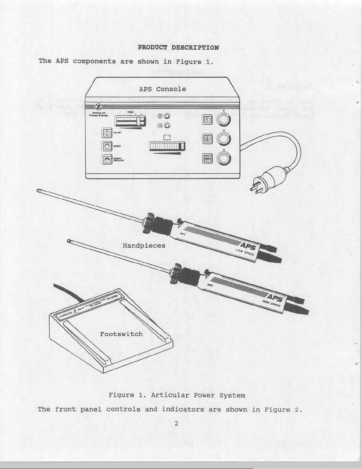
PRODUCT
DESCRIPTION
The APS
components
are
shown
APS
in
Figure
Console
1.
The
front
panel
Footswitch
Figure
controls
1.
Articular
and
indicators
2
Power
are
System
shown
in
Figure
2.
Page 6
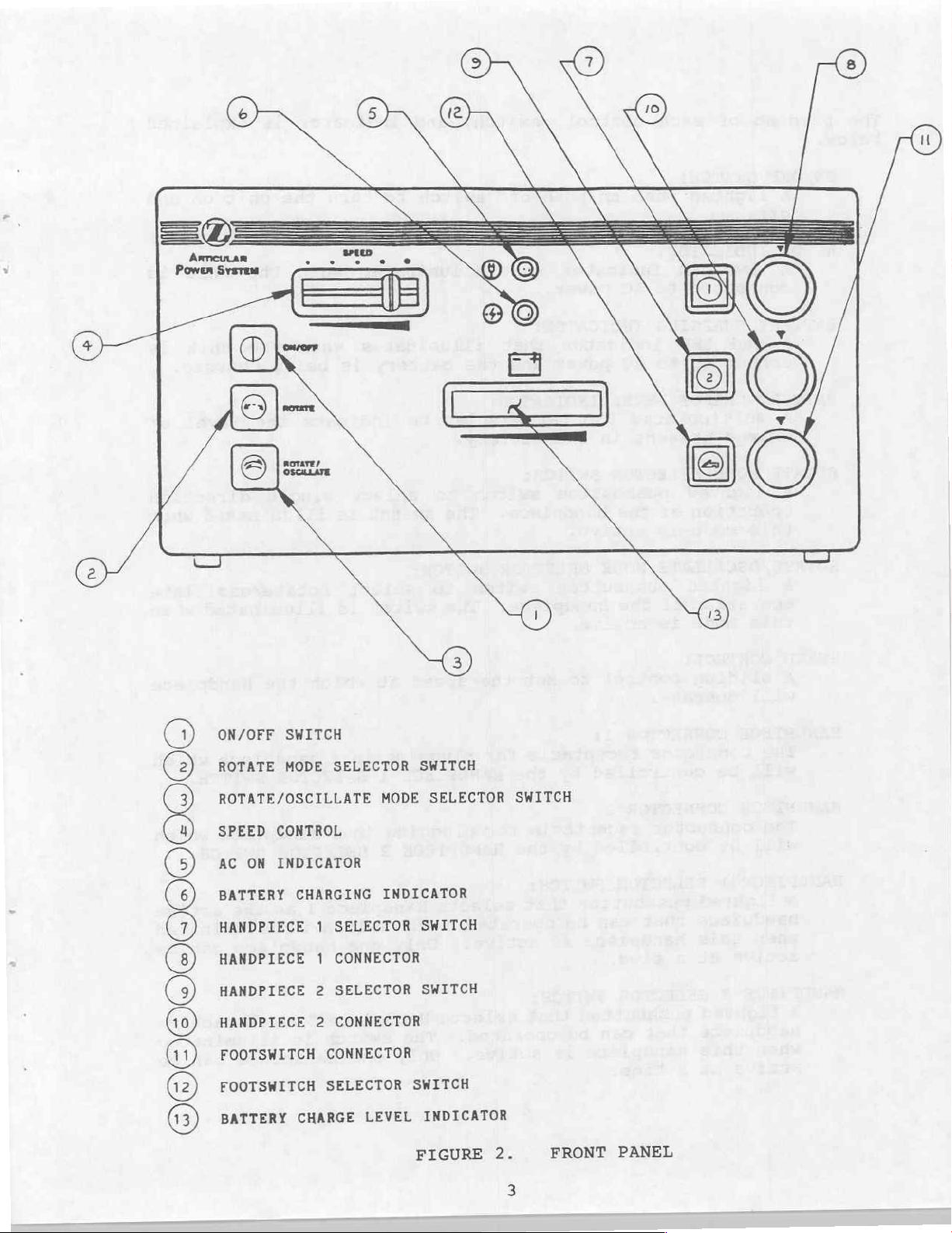
ON/OFF
ROTATE
ROTATE/OSCILLATE
SPEED
AC
BATTERY
HANDPIECE
HANDPIECE
HANDPIECE
HANDPIECE
FOOTSWITCH
FOOTSWITCH
BATTERY
0099009000000)
CONTROL
ON
INDICATOR
SWITCH
MODE
CHARGING
1
1
2
2
CONNECTOR
SELECTOR
CHARGE
SELECTOR
MODE
INDICATOR
SELECTOR
CONNECTOR
SELECTOR
CONNECTOR
LEVEL
SWITCH
SELECTOR
SWITCH
SWITCH
SWITCH
INDICATOR
FIGURE
2.
SWITCH
FRONT
PANEL
3
Page 7
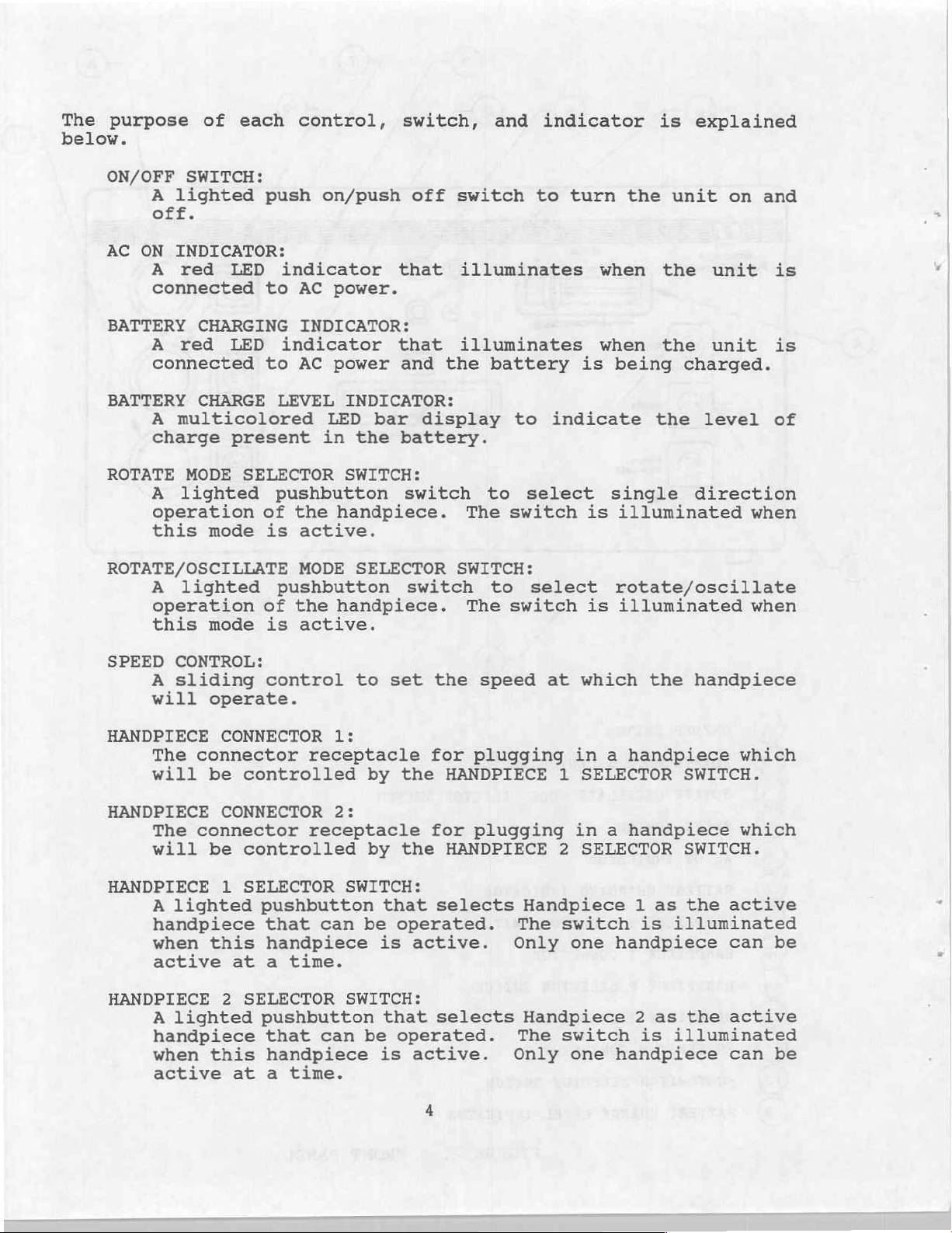
The
below.
purpose
of
each
control,
switch,
and
indicator
is
explained
ON/OFF
A
lighted
SWITCH:
off.
AC
ON
INDICATOR:
A
red LED
connected
BATTERY
A
red LED
CHARGING
connected
BATTERY
CHARGE
A
multicolored
charge
ROTATE
A
MODE
lighted
operation
this
ROTATE/OSCILLATE
A
mode
lighted
operation
this
mode
push
indicator
to
indicator
to
LEVEL
present
SELECTOR
pushbutton
of
is
pushbutton
of
is
on/push
AC
power.
INDICATOR:
AC
power
INDICATOR:
LED
in
the
SWITCH:
the
handpiece.
active.
MODE
the
SELECTOR
handpiece.
active.
off
that
that
and the
bar
battery.
switch
switch
switch
illuminates
illuminates
display
The
SWITCH:
The
to
turn
battery
to
indicate
to
select single
switch
to
select
switch
the
unit
is
when
when
being
the
the
the
is
illuminated
rotate/oscillate
is
illuminated
on
unit
unit
charged.
level
direction
and
is
is
of
when
when
SPEED
HANDPIECE CONNECTOR
HANDPIECE
HANDPIECE
HANDPIECE
CONTROL:
A
sliding
will
The
will
The
will
A
operate.
connector
be
CONNECTOR
connector
be
1
lighted
handpiece
when
this
active
2
A
lighted
handpiece
when
this
active
control
controlled
controlled
SELECTOR
pushbutton
that
handpiece
at a time.
SELECTOR
pushbutton
that
handpiece
at a time.
to
1:
receptacle
by
2:
receptacle
by
SWITCH:
that
can
be
is
SWITCH:
that
can
be
is
set
the
for
the
HANDPIECE
for
the
HANDPIECE
selects
operated.
active.
selects
operated.
active.
speed
plugging
plugging
Handpiece
The
Only
Handpiece
The
Only
at
which
in a handpiece
1
SELECTOR
in a handpiece
2
SELECTOR
1
switch
one
is
handpiece
2
switch
one
is
handpiece
the
handpiece
SWITCH.
SWITCH.
as
the
illuminated
as
the
illuminated
which
which
active
can
be
active
can
be
Page 8
FOOTSWITCH
The
in.
CONNECTOR:
connector
receptacle
where
the
footswitch
is
plugged
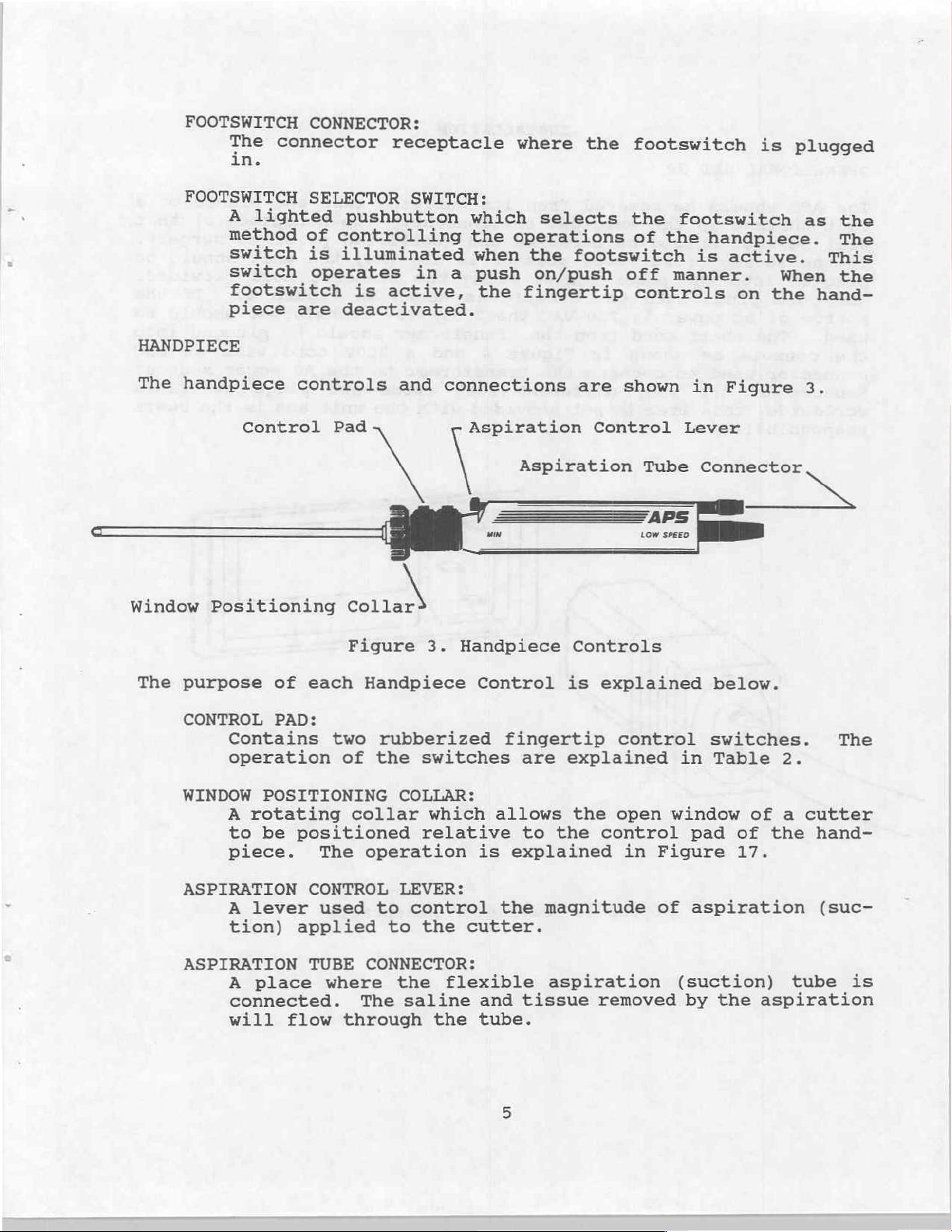
Window
FOOTSWITCH
HANDPIECE
The
handpiece
A
lighted
method
switch
switch
footswitch
piece
Control
Positioning
are
controls
SELECTOR
pushbutton
of
controlling
is
illuminated
operates
is
deactivated.
Pad
Figure
active,
and
(를
EN
SWITCH:
in
a
connections
3.
Handpiece
which
the
when
push
the
ος
um
selects
operations
the
footswitch
on/push
fingertip
are
Control
Aspiration
Controls
the
of
the
off
manner.
controls
shown
Tube
PS
LOW
SPEED
footswitch
handpiece.
is
active.
on
in
Figure
Lever
Connector
When
the
as
This
hand-
3.
the
The
the
The
purpose
CONTROL
Contains
operation
WINDOW
A
rotating
to
piece.
ASPIRATION
A
lever
tion)
ASPIRATION
A
connected.
will
of
each
PAD:
POSITIONING
be
positioned
CONTROL
applied
TUBE
place
flow
two
of
collar
The
used
where
through
Handpiece
rubberized
the
switches
COLLAR:
which
relative
operation
LEVER:
to
control
to
the
CONNECTOR:
the
The
saline
Control
is
cutter.
flexible
and
the
tube.
fingertip
are
allows
to
the
explained
the
magnitude
aspiration
tissue
is
explained
control
explained
the
open
control
in
removed
in
window
pad
Figure
of
aspiration
(suction)
by
below.
switches.
Table
the
2.
of a cutter
of
the
17.
aspiration
hand-
(suc-
tube
The
я
is
Page 9
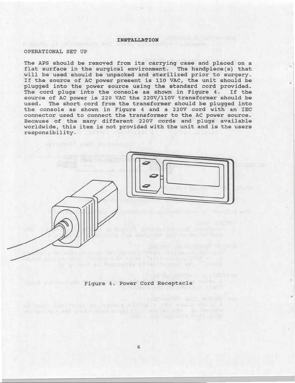
INSTALLATION
OPERATIONAL
The
will
plugged
The
source
used.
the
connector
Because
worldwide,
APS
flat
If
the
responsibility.
should
surface
be
used
source
into
cord
of
The
console
of
plugs
AC
used
SET
in
should
the
power
short
as
the
this
be
of
to
UP
removed
the
AC
power
into
cord
shown
connect
many
item
surgical
be
power
the
is
220
from
in
different
is
not
from
unpacked
present
source
console
VAC
the
Figure
the
provided
its
carrying
environment.
and
using
the
transformer
transformer
sterilized
is
the
as
shown
220V/110V
4
and
220V
with
110
a
cords
the
case
The
handpiece(s)
prior
VAC,
standard
220V cord
to
the
in
Figure
transformer
should
the
and
unit
and
unit
cord
be
AC
plugs
and
placed
to
4.
plugged
with
power
is
on
that
surgery.
should
provided.
If
should
into
an
source.
available
the
users
a
be
the
be
IEC
DY
Figure
4.
Power
Cord
Receptacle
Page 10
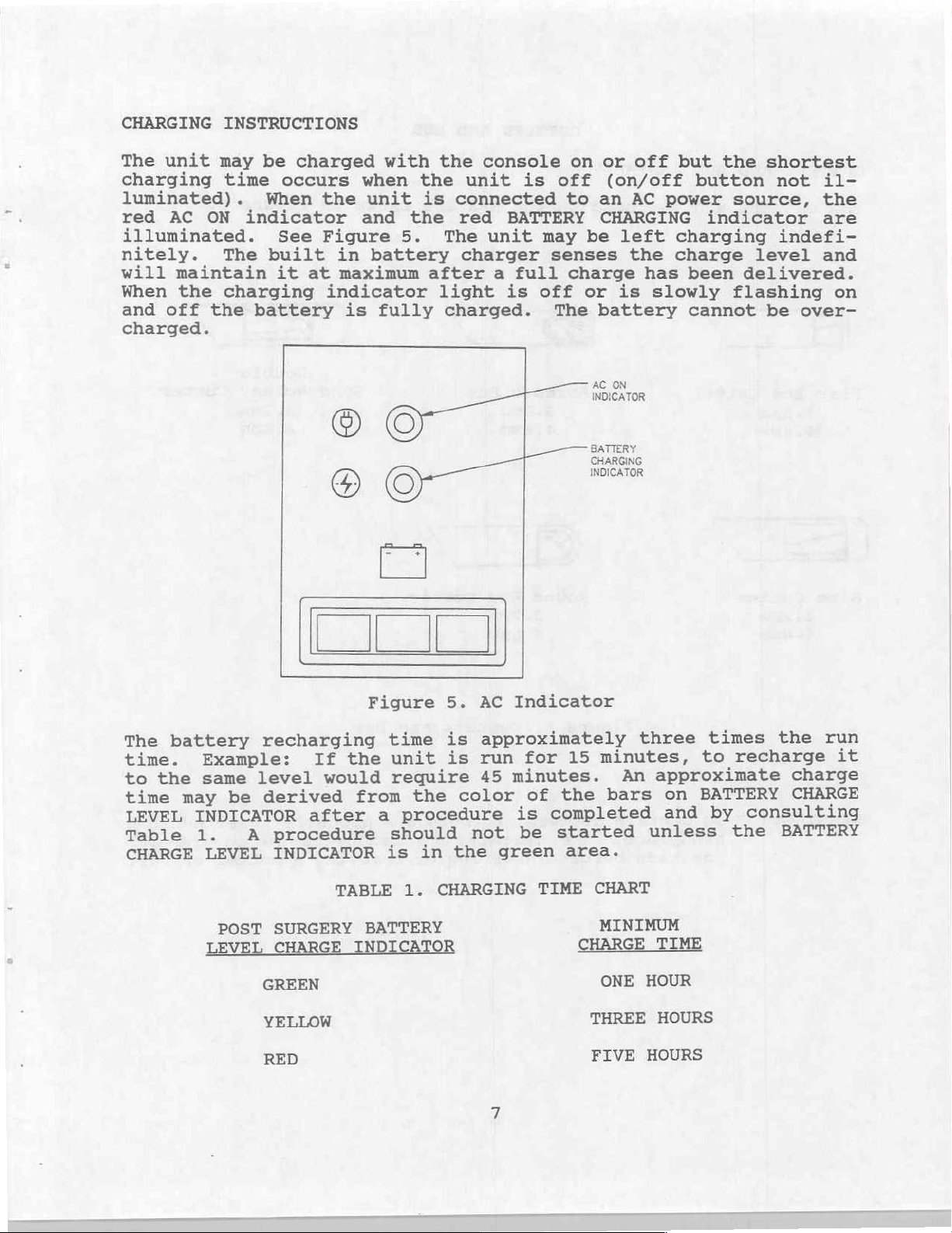
CHARGING
The
unit
charging
luminated).
red
AC ON
INSTRUCTIONS
may
time
illuminated.
nitely.
will
When
and off the
charged.
The
maintain
the
charging
be
charged
occurs
When
indicator
See
built
it at
battery
with
when
the
unit
and the red
Figure
in
battery
maximum
indicator
is
fully
the
5.
the
unit
is
connected
The
charger
after
light
charged.
console
is
BATTERY
unit
a
full
is
may
off
on
off
to an
CHARGING
be
senses
charge
or
The
battery
AC
INDICATOR
or
off
(on/off
AC
left
the
has
is
slowly
ON
but the
button
power
indicator
charging
charge
been
cannot
shortest
not
source,
indefi-
level
delivered.
flashing
be
over-
il-
the
are
and
on
The
time.
the
to
time
LEVEL
Table
CHARGE
battery
Example:
same
may
INDICATOR
1.
LEVEL
recharging
level
derived
be
procedure
A
INDICATOR
er
6)
Figure
the
If
would
from
after
a
TABLE
time
unit
require
the
procedure
should
in
is
1.
CHARGING
5.
AC
approximately
is
run
is
45
color
not
the
BATTERY
I
CHARGING
INDICATOR
Indicator
minutes,
15
for
minutes.
of
is
be
green
TIME
the
completed
started
area.
An
bars
CHART
on
and
times
to
BATTERY
by
three
approximate
unless
the run
recharge
charge
CHARGE
consulting
the
BATTERY
it
POST
LEVEL
SURGERY
CHARGE
GREEN
YELLOW
RED
BATTERY
INDICATOR
MINIMUM
CHARGE
ONE
THREE
FIVE
TIME
HOUR
HOURS
HOURS
Page 11
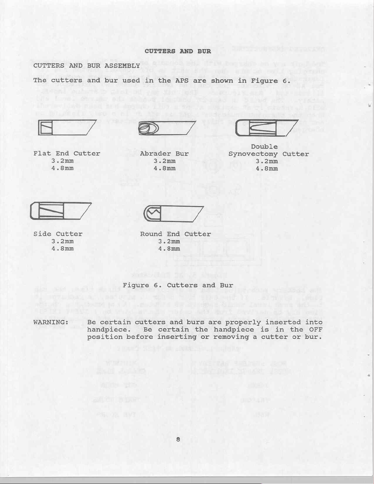
CUTTERS
AND
BUR
CUTTERS
The
cutters
η
Flat
3.2mm
4.8mm
Side
3.2mm
4.8mm
AND
End
Cutter
BUR
and
Cutter
ASSEMBLY
bur
used
in
D
Abrader
Round
the
7
3.2mm
4.8mm
End
3.2mm
4.8mm
APS
Bur
are
Cutter
shown
in
Figure
T7
Double
Synovectomy
3.2mm
4.8mm
6.
Cutter
WARNING:
Be
certain
handpiece.
position
Figure
cutters
before
6.
Be
certain
inserting
Cutters
and
burs
and
the
or
Bur
are
properly
handpiece
removing
is in
a
cutter
inserted
the
or
into
OFF
bur.
Page 12
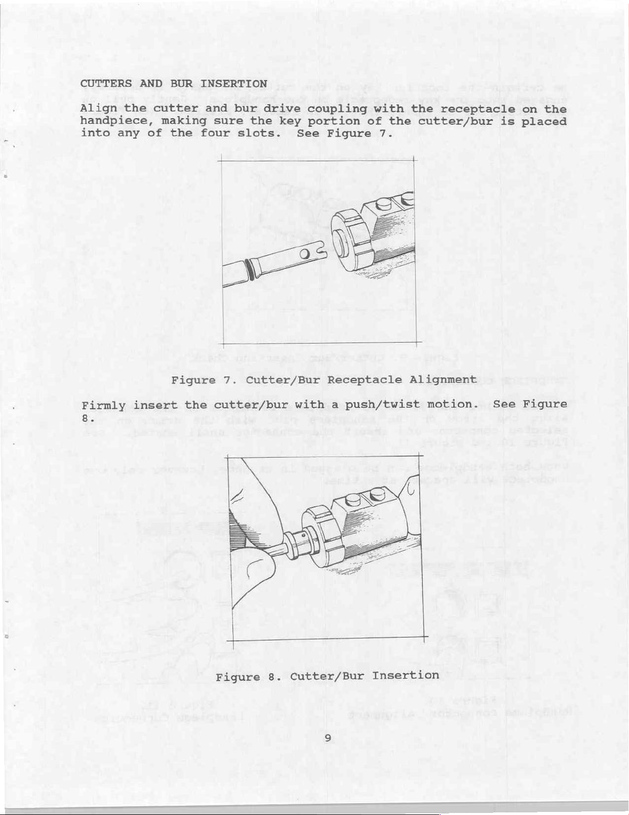
CUTTERS
AND
BUR
INSERTION
Align
handpiece,
into
Firmly
8.
the
any
insert
cutter
making
of
the
Figure
and bur
four
the
drive
sure
the
slots.
key
See
>
7.
Cutter/Bur
cutter/bur
with
coupling
portion
Figure
Receptacle
a
push/twist
with
of
7.
the
the
cutter/bur
Alignment
receptacle
motion.
is
See
on
the
placed
Figure
Cutter/Bur
Figure
8.
Insertion
Page 13
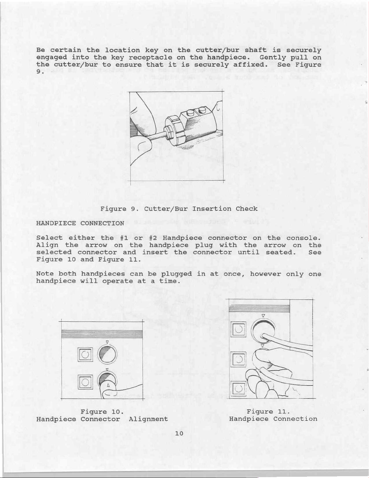
Be
certain
engaged
the
cutter/bur
9.
into
the
the key
to
location
receptacle
ensure
key
that
on
the
on
it is
cutter/bur
the
handpiece.
securely
shaft
affixed.
is
Gently
See
securely
pull
Figure
on
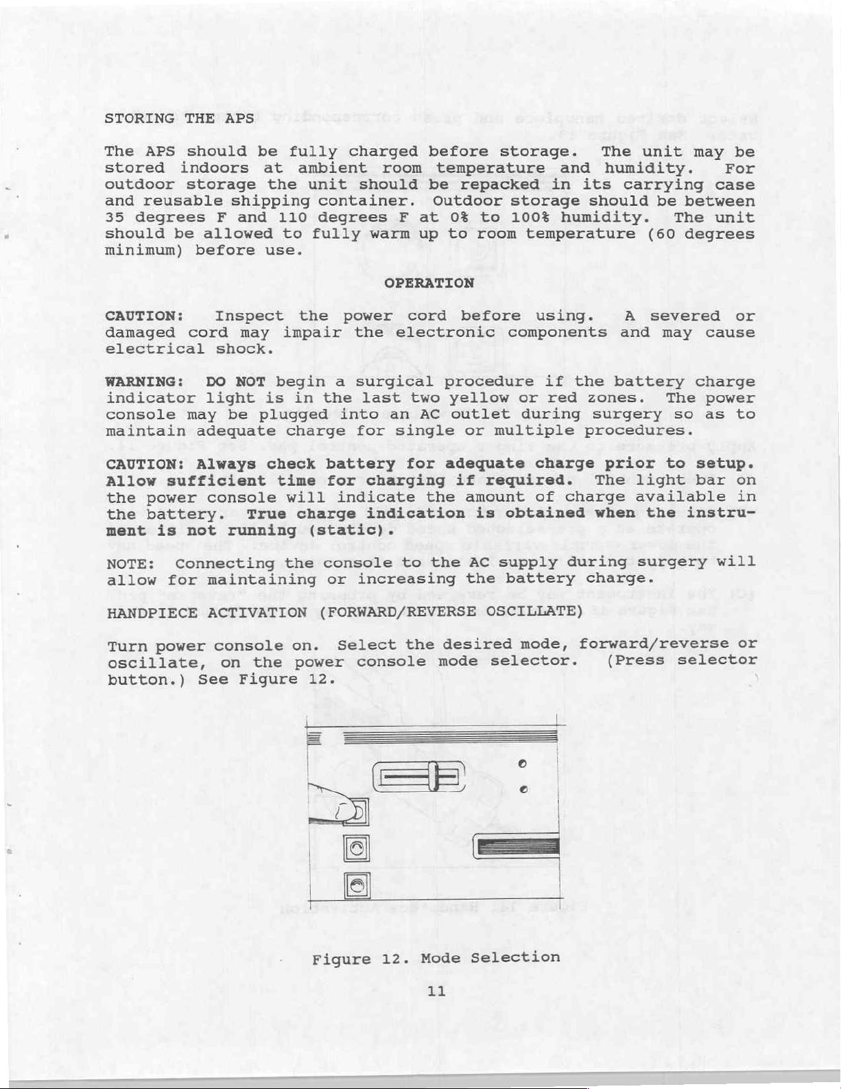
HANDPIECE
Select
Align
selected
Figure
Note
handpiece
both
CONNECTION
either
the
connector
10
and
will
Figure
the
arrow
Figure
handpieces
operate
on
#1
and
9.
Cutter/Bur
or
#2
the
11.
can
handpiece
insert
be
at a time.
Insertion
Handpiece connector
plug with
the
plugged
connector
in
at
once,
Check
the
until
however
on
the
arrow
seated.
console.
on
the
See
only
one
Handpiece
Figure
Connector
10.
Alignment
10
Figure
Handpiece
11.
Connection
Page 14
STORING
THE APS
APS
The
stored
outdoor
and
reusable
35
degrees
should
be
minimum)
CAUTION:
damaged
electrical
WARNING:
indicator
console
maintain
CAUTION:
Allow
the
the
ment
sufficient
power
battery.
is
should
indoors
storage
F
allowed
before
Inspect
cord
shock.
DO
light
may
be
adequate
Always
console
not
running
be
at
the
shipping
and
110
to
use.
may
NOT
impair
begin
is in
plugged
charge
check
time
will
True
fully
ambient
unit
container.
degrees
fully
the
the
battery
for
charge
(static).
charged
room
should
warm
OPERATION
power
the
a
surgical
last
into
an
for
charging
indicate
indication
before
temperature
be
Outdoor
F
at
0%
up
to
cord
electronic
procedure
two
yellow
AC
outlet during
single
for
adequate
if
the
storage.
repacked
storage
to
100%
room
before
components
or
multiple
required.
amount
is
obtained
and
in
its
humidity.
temperature
using.
if
the
or
red
charge
of
charge
The
unit
humidity.
carrying
should
A
and
be
(60
severed
battery
zones.
surgery
procedures.
prior
The
light
available
when
the
between
The
degrees
may
The
so as
to
instru-
may
For
case
unit
cause
charge
power
setup.
bar
be
or
to
on
in
NOTE:
allow
HANDPIECE
Turn
Connecting
for
power
oscillate,
button.)
maintaining
ACTIVATION
console
the
on
See
Figure
the
console
or
(FORWARD/REVERSE
on.
Select
power
12.
Figure
to
increasing
the
console
Mode
12.
the
desired
mode
=
AC
supply
the
battery
OSCILLATE)
mode,
selector.
Selection
during
surgery
charge.
forward/reverse
(Press
will
or
selector
EL
Page 15
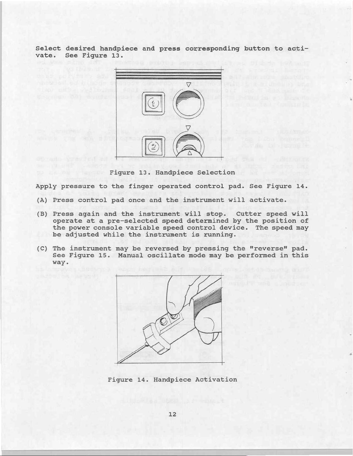
Select
vate.
desired
See
Figure
handpiece
13.
and
press
corresponding
button
to
acti-
Apply
(A)
(B)
(C)
pressure
Press
Press
operate
the
power
be
adjusted
The
See
way.
instrument
Figure
Figure
to
the
control
again
at a pre-selected
console
pad
and the
while
may
15.
Manual
variable
13.
finger
once
instrument
the
instrument
be
reversed
oscillate
Handpiece
operated
and the
speed
speed
Selection
control
instrument
will
determined
control
by
mode
stop.
is
running.
pressing
may
pad.
will
Cutter
by
device.
the
be
performed
See
activate.
the
Figure
speed
position
The
"reverse"
speed
in
14.
will
of
may
pad.
this
Figure
14.
Handpiece
12
Activation
Page 16
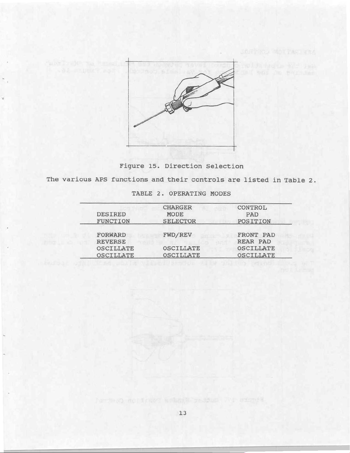
The
various
Figure
APS
functions
TABLE
DESIRED
FUNCTION SELECTOR
FORWARD FWD/REV
REVERSE
OSCILLATE
OSCILLATE
15.
and
2.
Direction
their
OPERATING
CHARGER
MODE
OSCILLATE
OSCILLATE
Selection
controls
MODES
are
CONTROL
POSITION
FRONT
REAR
OSCILLATE
OSCI
listed
PAD
PAD
PAD
T
in
Table
2.
13
Page 17
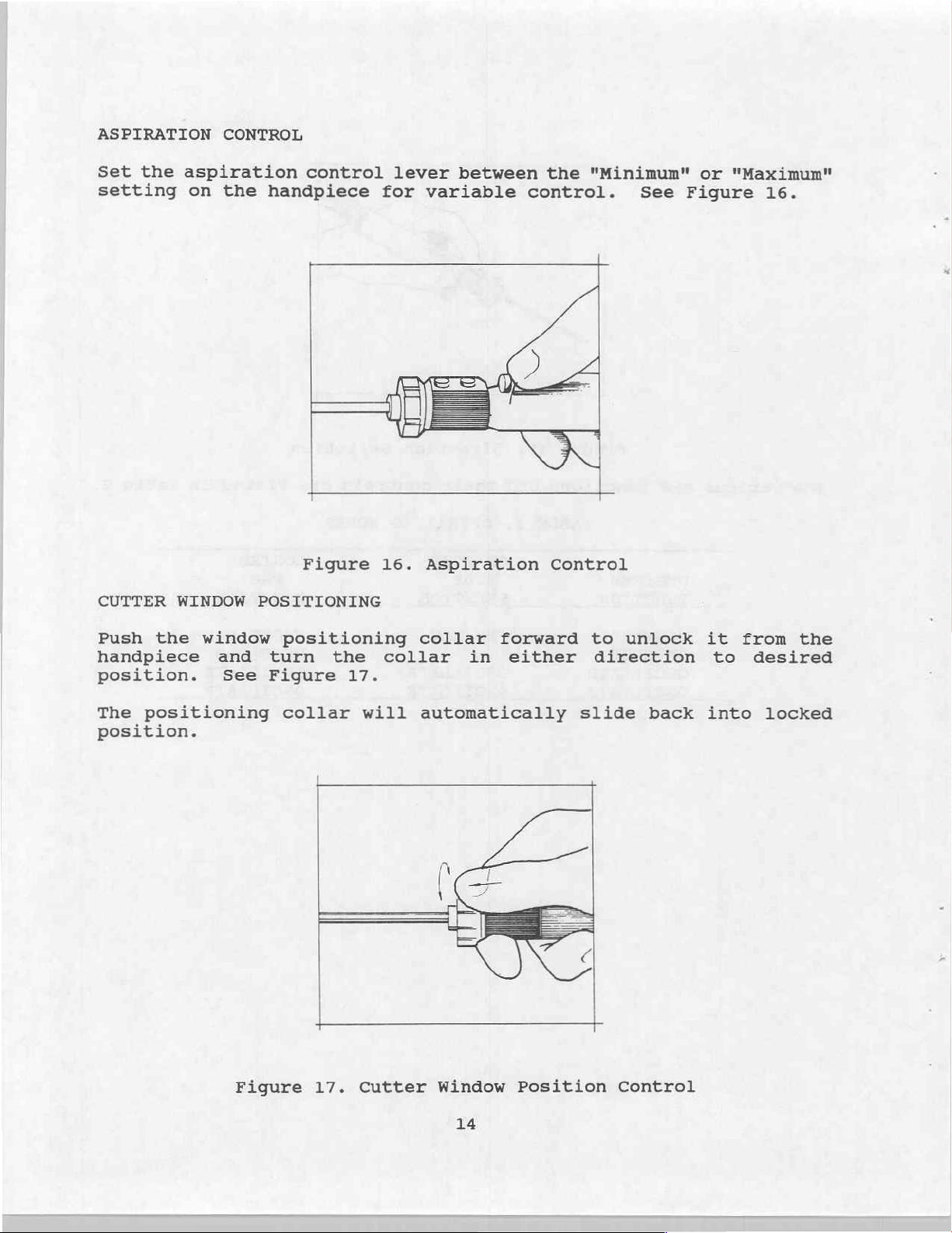
ASPIRATION
Set
the
setting
CONTROL
aspiration
on
the
control
handpiece
lever
for
between
variable
the
"Minimum"
control.
See
or
"Maximum"
Figure
16.
CUTTER
Push
handpiece
position.
The
position.
the
positioning
WINDOW
window
and
See
Figure
POSITIONING
positioning
turn
Figure
collar
the
17.
16.
collar
will
Aspiration
collar
automatically
in
forward
either
Control
to
direction
slide
unlock
back
it
to
into
from
desired
locked
the
Figure
17.
Cutter
Window
14
Position
Control
Page 18

CUTTER
OR
BUR
REMOVAL
Grasp
other.
FOOT
the
Pull
CONTROL
cutter
the
CONNECTION
or
two
Figure
bur
in
components
18.
one
hand
apart.
Cutter/Bur
and
the
APS
See
Removal
Figure
handpiece
18.
in
the
Insert
console.
the
activated
regulate
To
receptacle.
use
footpad;
fingertip
that
the
foot
foot
control
See
Figure
and the
the APS
pedal,
the
instrument
controls,
illumination
plug
19.
When
fingertip
handpieces.
press
simply
turns
Figure
the
will
19.
into
Press
button
the
press
off.
Foot
corresponding
the
illuminates,
controls
desired
respond
the
Control
blue
foot
on
the
rotation
accordingly.
blue
button
Connection
receptacle
control
the
handpiece
indicated
on
button
foot
To
the
on
the
above
pedal
no
longer
on
the
reactivate
console
is
so
15
Page 19

OPERATIONAL
CHECKOUT
POWER
Unpack
allowed
degrees
steps
results
sections
Plug
of
the
110V
Depress
that
locks
Depress
MODE
it
selector
CONSOLE
the
to
F)
should
obtained
of
console
AC
the
becomes
in
the
the
console
acclimate
for
24
hours
be
performed
are
the
manual.
STEP
into
power.
ON/OFF
illuminated
depressed
ROTATE/OSCILLATE
switch.
from
to
before
not
a
switch
portion.
its
room
with
as
source
such
and
carrying
ambient
operational
the
indicated,
case.
temperature
checkout.
indicated
see
The red
CHARGING
illuminate.
The
MODE
HANDPIECE
should
The
should
the
ON/OFF
selector
illuminate.
ROTATE
not
ROTATE/OSCILLATE
selector
illuminated.
The
console
results.
the
RESULT
AC
indicators
switch,
1
SELECTOR
MODE
be
switch
should
(minimum
The
following
If
troubleshooting
ON
and
switch
selector
BATTERY
the
and the
switches
ROTATE
switch
illuminated
should
be
60
the
should
and
MODE
be
Depress
selector
HANDPIECES
The
SPEED
handpieces
console.
An
following
APS
operational
quired.
results.
the
switch.
handpiece
The
If
troubleshooting
peated
for
CAUTION:
ROTATE
operational
from
the
power
following
the
results
section
each
handpiece.
Operational
formed
and
carrying
console
with
the
steps
of
check
a
MODE
checkout
LOW
SPEED
case
that
should
obtained
this
manual.
out
cutter/bur
The
selector
illuminated.
selector
illuminated.
steps
APS
and
plug
passes
be
performed
are
of
not
handpieces
installed.
ROTATE/OSCILLATE
switch
The
switch
apply
to
handpiece.
them
the
into
above tests
with
as
indicated,
The
steps
should
should
ROTATE
should
both
Unpack
the
should
not
MODE
not
MODE
the
the
HIGH
power
is
indicated
see the
be
be
per-
be
be
the
re-
re-
16
Page 20

STEP
RESULT
Turn
it in
MODE
the
selector
nated).
selector
to
the
Depress
the
operated
Depress
operated
Depress
operated
Depress
operated
Depress
cutter
selector
console
the
ROTATE
Depress
switch
handpiece
the
receptacle)
control
the
control
the
control
the
control
the
switch.
switch
front
STEP
front
HANDPIECE
ON
and
mode
place
(ROTATE
illumi-
the
HANDPIECE
corresponding
to be
pad
pad
rear
pad
rear
pad
tested.
(closest
finger
once.
finger
again.
finger
once.
finger
again.
to
2
The
handpiece
a
(direction
clockwise
looking
receptacle).
The
operating.
The
a
The
operating.
The
should
HANDPIECE
should
handpiece
handpiece
counterclockwise
handpiece
HANDPIECE
not
be
should
may
be
determined
into
RESULT
be
2
illuminated.
the
should
should
should
selector
1
illuminated.
selector
operate
direction
cutter
operate
motion.
switch
switch
in
by
stop
in
stop
The
Depress
selector
Depress
switch
depressed
the
Depress
switch
from
the
the
switch.
FOOTSWITCH
the
such
FOOTSWITCH
the
such
depressed
HANDPIECE
that
it
position.
that
selector
locks
selector
unlocks
it
position.
1
in
HANDPIECE
The
should
HANDPIECE
should
FOOTSWITCH
The
should
The
FOOTSWITCH
should
2
illuminated.
be
not
1
selector
be
illuminated.
illuminate.
be
not
selector
selector
selector
illuminated.
switch
The
switch
switch
switch
17
Page 21

COMPLETE
SYSTEM
The
plete
following
system.
must have been
steps.
results.
shooting
With
position
OSCILLATE
the
selector
Depress
operated
Depress
operated
Depress
operated
The
following
If
the
section
STEP
the
console
enter
mode
ROTATE/OSCILLATE
switch.
the
control
the
control
the
control
operational
The
preceding
successfully
steps
results
of
this
in
the
by
front
pad
front
pad
rear
pad
ROTATE/
depressing
once.
again.
once.
check
are not
manual.
the
MODE
finger
finger
finger
two
checkouts
completed
should
ON
out
will
test
before
be
performed
as
indicated,
The
ROTATE/OSCILLATE
switch should
The
handpiece
a
clockwise
The
operating.
The
an
approximately
clockwise
approximately
counterclockwise
returning
direction
fashion.
handpiece
handpiece
oscillatory
the
(CONSOLE
with
directions.
motion
to
in
unit
and
HANDPIECES)
performing
the
see
RESULT.
the
illuminate.
should
should
1.
1
operate
should
operate
fashion
second
followed
second
motion
a
a
as a com-
these
indicated
trouble-
mode
in
stop
in
with
of
by
of
then
clockwise
repeating
Depress
operated
Depress
operated
Move
the
front
left.
Move
the
front
right.
Depress
operated
control
control
of
of
control
the
the
SPEED
the
SPEED
the
the
rear
pad
front
pad
CONTROL
console
CONTROL
console
front
pad
finger
again.
finger
once.
on
to
on
to
finger
once.
the
the
the
the
The
operating.
The
a
The
should
The
should
The
operating.
18
handpiece
handpiece
clockwise
speed
decrease.
speed
increase.
handpiece
should
should
direction.
of
the
of
the
should
operate
handpiece
handpiece
stop
in
stop
Page 22

FOOTSWITCH
=
The
trol
and
following
of
SYSTEM)
steps.
results.
shooting
ROTATE
Plug
APS
the
console.
FOOTSWITCH
Depress,
then
the
control
handpiece.
Depress
treadle
Release
footswitch.
the
The
If
section
MODE
footswitch
in
back
pad
and
of
the
operational
APS.
must
be
following
the
selector
STEP
SELECTOR
turn,
finger
on
hold
the
footswitch.
left
Ereadte
The
previous
successfully
steps
results
of
this
switch.
into
Depress
switch.
the
front
operated
the
=
the
check
three
should
are not
manual.
the The
the
and The
active
left
the
of
out
will test
checkouts
completed
be
performed
as
indicated,
Before
should
position
operate.
The
clockwise
a
The
operating.
(CONSOLE,
before
beginning,
FOOTSWITCH
latch
and
handpiece
handpiece
handpiece
the
footswitch
performing
with
the
see the
RESULT
SELECTOR
in
the
illuminate.
should
direction.
HANDPIECE,
indicated
trouble-
depress
depressed
should
operate
should
con-
these
the
switch
not
in
stop
Depress
treadle
Release
footswitch.
the
and
of
the
the
hold
footswitch.
right
the
treadle
right
of
handpiece
The
counterclockwise
a
The
handpiece
operating.
should
should
operate
direction.
stop
in
19
Page 23

INSPECTION
This
given
section
to
viced.
CONSOLE
The APS
other
surgery.
The
switches
in
the
instructions,
When
the
BATTERY
unless
may
be
HANDPIECE
The
other
surgery.
the
outside.
Manual.
cracked,
console
foreign matter
Operational
plugged
it
found
handpiece
foreign matter
or
explains
the APS
The
power
on
please
in
CHARGE
is
fully
in
should
The
The
handpiece
Cleaning
handpiece
cut. The
console
should
the
and
LEVEL
the
the
detailed
be
that
cord
could
should
front
Checkout
see
the
turned
INDICATOR.
charged
Operations
be
clean
that
could
should
instructions
cord
control
and
clean
of
the
section
Operations
on,
the
to
and
pads
visual
handpieces
of
dirt,
accumulate
not
be
unit
of
APS
should
The
this
Manual.
of
accumulate
be
level.
dirt,
clean
may
connector
should
inspection
whenever
dust,
during
frayed,
should
this
Manual.
unit
dust,
during
on
be
found
not
blood,
cracked
operate
manual.
display
should
Charging
blood,
the
should
inside
in
be
that
they
storage
as
For
green
not
instructions
storage
the
not
cut
or
should
are
ser-
saline,
or
use
or
broken.
explained
cleaning
bars
be
stored
saline,
or
use
as
well
Operations
be
frayed,
damaged.
be
or
in
in
or
in
as
FOOTSWITCH
The
other
footswitch
foreign matter
surgery.
inspection.
footswitch
The
cord
should
plastic
The
should
cover
be
that
cover
should
not
clean
could
over
be
of
dirt,
accumulate
the
not
be
frayed,
20
dust,
during
footswitch
cut,
cracked,
cracked,
blood,
storage
may
or
cut.
be
or
saline,
or
removed
split.
use
or
in
for
The
Page 24

REPAIR
CONSOLE
The
following
should
the
problems.
DISASSEMBLY/ASSEMBLY
SYMPTOM:
PROBABLE
Bad
fuse
A.C.
connected
Bad
A.C.
Bad
charger.
TROUBLESHOOTING
be
used
Power
CAUSE
in
Power Entry
connector
to
charger.
Board
is a troubleshooting
in
conjunction
with
sections
does
not
come
Module.
assembly
assembly.
not
guide
the
of
for
BLOCK
this
on
REPAIR
Check
Reconnect
Assembly
and
Charger
Remove
Assembly
Remove
(22-6316-000-00)
the
APS
console.
DIAGRAM
manual
replace
(15-3092-032-00)
A.C.
(Figure
to
250mA
Connector
(22-6316-000-00)
and
replace
A.C.
(15-3902-290-00)
and
replace
8)
and
correct
fuses.
Board
Charger
It
to
SYMPTOM:
PROBABLE
Open
BACC
harness
Bad
connection
wire
relay
board.
CAUSE
harness,
to
"Charging"
charging.
from
battery.
or
bridge
charger
or
from BACC
light
on
to
A.C.
not
lighting
REPAIR
Remove
BACC
(15-3922-300-00),
Remove
when
and
and
Assembly
battery
check
Harness
replace
should
continuity
Assembly
repair
A.C.
(15-3092-290-00)
be
of
open.
Board
23
Page 25

SYMPTOM:
Far
right
lighting,
charge.
most
and
L.E.D.
battery
on
charge
has had
level
indicators
sufficient
time
not
to
PROBABLE
Bad
battery.
SYMPTOM:
PROBABLE
Faulty
SYMPTOM:
PROBABLE
Bad
speed
CAUSE
CAUSE
control
CAUSE
control
Erratic
indicators.
board.
Speed
control
assembly.
or
incorrect
not
functioning.
REPAIR
Remove,
Battery
required.
light
test,
(22-6320-000-00)
display
REPAIR
Remove,
Control
as
required.
REPAIR
Remove
Com
Er
test,
Board
and
o
(15-3922-034-00).
and
of
repair
(15-3922-296-00)
replace
Assembly
LED
or
replace
replace
as
charge
Speed
Faulty
SYMPTOM:
PROBABLE
Blown
Faulty
control
CAUSE
bulb.
switch.
One
board.
of
the
front
panel
22
Remove,
replace Control
test
and
(15-3922-296-00)
switches
REPAIR
Remove
(22-26954-00-00).
Check
if
out.
of
switch.
replace
2)
267.258)
22-6289-003-00
bulb
not
and
contacts
Also
as
9 —
lighting.
replace
check
Re-solder
required.
0)
OF
as
repair
as
required.
and
=
070
required.
or
Board
bulb
adjust
soldering
and/or
Use
or
Page 26

SYMPTOM:
Handpiece
functioning
doesn't
properly.
run and
console
indicators
are
PROBABLE
Open
harness
ground.
Faulty
SYMPTOM:
PROBABLE
Open
harness
Faulty
bad
direction
CAUSE
connection
assembly.
control
Handpiece
CAUSE
connection
assembly.
control
in
board.
in
board.
logic.
handpiece
Possible
runs
in
handpiece
Possible
one
REPAIR
Remove
and
Harness
(15-3922-301-00)
connection.
Remove,
Control
as
required.
direction
test,
Board
only.
REPAIR
Remove
Harness
and
(15-3922-301-00)
connection.
Remove,
Control
as
required.
test,
Board
test
continuity
Assembly
and
repair
(15-3922-296-00)
test
or
continuity
Assembly
and
repair
or
(15-3922-296-00)
of
repair
replace
of
repair
replace
SYMPTOM:
РВОВАВ:
Open
harness
Faulty
faulty
or
direction
Handpiece
.AUSE
connection
assembly.
control
forward/reverse
board.
logic.
in
handpiece
doesn't
Possible
timer,
oscillate.
REPAIR
Remove
Harness
(15-3922-301-00)
connection.
Remove,
Control
as
23
and
test,
Board
required.
test
continuity
Assembly
and
repair
(15-3922-296-00)
or
of
repair
replace
Page 27

SYMPTOM:
Handpiece
charge.
runs
slow
with
charge
indicators
showing
full
PROBABLE
Faulty
bad
SYMPTOM:
(Q1)
PROBABLE
Bad
battery.
Faulty
SYMPTOM:
CAUSE
control
or
CAUSE
control
board.
(U16).
Excessively
console.
board.
Handpiece
stop
when
Possible
>
fast
runs
when
button
discharge
trigger
is
depressed
REPAIR
Remove,
Control
as
required.
time
REPAIR
Remove,
Battery
necessary.
Remove,
Control
as
required.
is
test,
Board
of
repair
(15-3922-296-00)
charged
test
(22-6320-000-00)
test,
Board
repair
(15-3922-296-00)
depressed,
a
second
and
but
time.
or
replace
battery
replace
or
replace
will
in
as
not
PROBABLE
Faulty
wrong
direction
SYMPTOM:
PROBABLE
Faulty
Faulty
assembly.
resistor
CAUSE
control
logic.
Handpiece
switch.
CAUSE
switch.
footswitch
board.
at
(R56),
wire
REPAIR
Possibly
or
bad
doesn't function
harness
Remove,
Control
as
REPAIR
Check
(00-5039-028-00)
Remove
Wire
(15-3922-302-00)
24
test,
Board
required.
properly
and
and
Harness
repair
(15-3922-296-00)
when
replace
as
replace
as
or
replace
using
foot
Footswitch
required.
Footswitch
Assembly
required.
Page 28

HANDPIECE
The
following
it
should
section
SYMPTOM:
of
is
be
used
this
Handpiece
a
troubleshooting
in
conjunction
manual
to
doesn't
correct
run.
guide
with
problems.
for
the
the
APS
Handpieces.
DISASSEMBLY/ASSEMBLY
PROBABLE
Open
Bad
Bad
Bad
motor
instrument
motor
trigger
SYMPTOM:
PROBABLE
Motor
assembly
CAUSE
assembly.
CAUSE
adaptor
output
wire.
cord
assembly.
Handpiece
Os
loose
shaft.
assy.
runs
on
but
motor
REPAIR
Re-solder
Replace
Replace
Handpiece;
Low
Replace
cutter
REPAIR
Tighten
Adaptor.
wire.
Instrument
(15-3926-028-00)
Motor
(15-3930-001-00
15-3901-001-00)
Speed
Handpiece.
Trigger
(15-3901-005-00).
doesn't
(22-6469-000-00)
rotate.
Set
.
for
on
Cord
Assembly
High
Assembly
Motor
Assy.
Speed
for
Screw
Drive
Gear
SYMPTOM:
damage
PROBABLE
Shorted
in
Unit
CAUSE
trigger
motor
runs
_
assembly.
assembly.
without
Replace
(15-3930-001-00
Handpiece;
Low
depressing
一
REPAIR
Replace
(15-3901-005-00)
25
Speed
trigger.
Motor
for
15-3901-001-00
Handpiece)
Trigger
.
Assembly
High
.
Assembly
Speed
for
Page 29
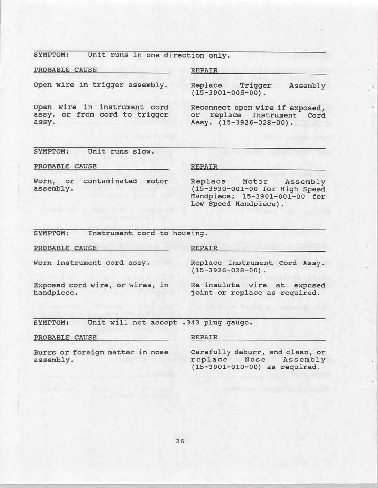
SYMPTOM:
Unit
runs
in
one
direction
only.
PROBABLE
Open
wire
Open wire
assy.
or
assy.
SYMPTOM:
PROBABLE
Worn,
or
assembly.
SYMPTOM:
PROBABLE
CAUSE
in
trigger
in
instrument
from cord
Unit
CAUSE
contaminated
Instrument
CAUSE
to
runs
assembly.
cord
trigger
slow.
motor
cord
to
REPAIR
Replace
(15-3901-005-00)
Reconnect
or
Assy.
REPAIR
Replace
(15-3930-001-00
Handpiece;
Low
housing.
REPAIR
Trigger
open
replace
Instrument
(15-3926-028-00).
Motor
15-3901-001-00
Speed
Handpiece)
.
wire
for
Assembly
if
exposed,
Assembly
High
.
Cord
Speed
for
Worn
instrument
Exposed
handpiece.
SYMPTOM:
PROBABLE
Burrs
or
assembly.
cord
CAUSE
foreign
wire,
Unit
cord
or
will
matter
assy.
wires,
not
in
in
accept
nose
Replace
(15-3926-028-00)
Re-insulate
joint
.343
plug
REPAIR
Carefully
replace
(15-3901-010-00)
26
Instrument
or
replace
gauge.
deburr,
wire
Nose
.
Cord
at
as
required.
and
as
required.
Assy.
exposed
clean,
Assembly
or
Page 30

SYMPTOM:
Collar
on
nose
assembly
will
not
retract
properly.
PROBABLE
Foreign
assembly.
CAUSE
matter
inside
nose
REPAIR
Remove
and
repair
(15-3901-010-00)
.
Nose
Assembly
27
Page 31

CONSOLE
DISASSEMBLY/ASSEMBLY
These
thru
the
Remove
(22-6329-000-00)
Cut
Disconnect
Remove
using
Remove
Battery
Remove
Assembly
Control
Remove
Assembly
from
Assembly
hold
inspected
instructions
23,
CONSOLE
Power
off
Wire
Safety
T-5039-7,
Battery
Bracket
Control
(15-3922-300-00),
Assembly
the
(15-3922-031-00)
Barrier
(15-3902-300-00).
the
board
Follow
TROUBLESHOOTING
Supply
.
Tie - red
leads
Screws
(22-6320-000-00)
Board
A.C.
Strip
to
at
this
from
(22-15925-00-00).
(15-3922-034-00)
Board
should
the
steps
Cover
(22-16699-00-00)
and
battery.
(22-6323-000-00)
(15-3922-296-00)
Handpiece
Assembly
leads,
be
as
black
by
(15-3902-290-00)
(22-6296-000-00)
Then
the
chassis
point
for any
(Note:
damage).
used
required
section
in
conjunetion
for
of
by
removing
this
(22-6377-001-00,
removing
Harness
and
A.C.
on
remove
from
by
Connector
The
Electronics
two
disconnecting
Assembly
(4)
Kep
Nuts
the
A.C.
the
(4)
Shield
Screws
by
Assembly
board,
Kep
with
repair
after
manual.
the
(4)
Screws
22-6377-002-00).
Cover
(22-6321-000-00)
the
(15-3922-301-00),
(22-16698-00-00)
BACC
(22-6313-000-00).
disconnecting
(15-3902-032-00)
and
BACC
Nuts
(22-15922-00-00)
(22-6313-000-00)
FIGURES
referencing
Harness
the
A.C. Tub
Harness
should
20
and the
Speed
leads
that
be
Remove
the
BACC
Harness
(22-6316-000-00).
Remove
the
A.C.
Charger
(22-6317-000-00).
Remove
(22-15863-00-00).
Remove
(22-6744-000-00)
Remove
Kep
Remove
(2)
the
Speed
the
A.C.
the
Handpiece
Nuts
(22-6328-000-00)
the
Foot
Retainers
Tub
.
Control
(22-16765-00-00).
Control
Assembly
Harness
Assembly
(22-6316-000-00)
Assembly
on
Wire
(15-3922-300-00)
(15-3922-034-00)
(15-3922-031-00)
Assemblies
each.
Harness
Assembly
28
from
by
removing
by
(15-3922-301-00)
(15-3922-302-0C)
the
by
removing
removing
the
(4)
by
A.C.
Screws
the
(2)
removing
by
Charger
(2)
Pot
Screws
removing
Clips
the
(3)
the
Page 32

HANDPIECES
These
thru
instructions
26,
HANDPIECE
Disassembly
Place
Remove
Remove
Remove
should
Follow
the
TROUBLESHOOTING
of
Instrument:
unit
in
T-5039-88
Instrument
Use
T-5039-22
Remove
Nose
Use
end
Assembly
T-5039-46A
Cord
assembly.
Trigger
Using
Housing
Assembly
an
X-Acto
(22-16200-00-00),
be
used
steps
as
section
and
secure
Assembly
to
remove
cap
to
expose
(15-3901-010-00).
&
B
or
T-5039-46C
(15-3901-005-00).
knife,
cut
in
conjunction
required
of
this
in
vise.
after
manual.
(15-3901-028-00).
End
Cap
Retainer
wire
connections,
through
remove
then
and
rubber
a
trigger
with
ref
a
(22-15913-00-00).
then
strap
boot
de-solder
wrench
where
assembly.
FIGURES
i
to
remove
it
mates
24
cord.
nose
with
Remove
Repair
Test
Repair
Remove Switch
Use
T-5039-22
Remove
Switch
Motor
Use
T-5039-88
T-5039-50.
and
Test
of
forward
Test
11.4
least
of
Nose
Remove
(22-15963-00-00)
With
Mount
Mount
Nut
(22-15917-00-00).
Assembly
Components
and
reverse
Motor
(15-3930-001-00)
volts - 2
750
RPM.
Assembly
Front
Cover
assembly
(22-15918-00-00).
to
remove
switch
(15-3930-001-00).
to
secure
or
speed
unit
Sub-assemblies:
of
Motor
using
amps.
Check
to
(15-3901-010-00).
(22-15961-00-00)
using a 1/16
apart,
clean
contaminated
mount
while
Assembly
assure
drift
nut.
removing
an
adjustable
forward
by
removing
punch.
components.
motor
assembly
(15-3930-001-00).
power
and
both
supply
reverse
Pins
with
e
set
speeds
at
of
at
Replace
any
damaged
15-3901-010-00.
or
worn
29
components
and
re-assemble
per
AP
Page 33

22-16699-00-00
(2
REQ'D)
15931
м
A
gf
6377-01
Figure
20.
Console
Top
30
Cover
22-6325-001-00
Disassembly/Assembly
Page 34

(SAI
22-16598-00-00
46)
‚
MUT
FROM
©
oo
ES
ta
ta
43
6321
D
42
6322
들
1
i
=
—
22-16878-00-00
Page 35

15-3922-304-00
TOP
RP-3
15-3922-296-00
(4
REOD)
6313
THREAD
(4
REO‘)
LOCKER
(6114)
1
242
\,
x
Ree
so
TOR
TOP
15-3922-297-00
RP-11
Î6-3922-301-009
AR
НЕО
О)
6313
THREAD
(6114)
(4
REO'D)
LOCKER
242
|
15-3922-298-00
RP-10
15-3922-303-00
Figure
6328
(6
22.
REQ'D)
22-16765-00
(2
REO'D)
15-3922-302-06
RP-13
E
Console
Wire
Harness
32
&
Circuit
Cards
i i
Disassembly/Assembly
TOK
1
Page 36

Figure
23.
Console
(2
REO'D)
Battery
Charger
33
6
22-6744-000-00
(2
REG'D)
Disassembly/Assembly
BOOT
5
(SAI
5)
15-3922-031-00
SS
RP=25
SRI
>
2
^
Page 37

15-3926-028-00
RP-16
Figure
24.
Handpiece
End
34
Cap
Retainer
Disassembly/Assembly
Page 38

Loctite
USE
(SAI
T-5039-129
ni
TOA
3)3-
8
22-6287-000-00\_
22-15914-01-00
RP=19
Δίδαι
4)
Low
15-3901-001-00
USE
AND
RP-18
Speed
T-5039-14b
T-5039-93
ee
Speed
19h
15-390-001-00
Figure
25.
Handpiece
Disassembly/Assembly
Motor
&
Aspiration
Control
Page 39

USE
22-6589-000-00
22-15915-00-00
RP-23
THRU
D1 & D2
(SAL
USE
T-5039-49
RP-20
T-5039-16
11r0F
12706
ピン
7)
в
~
THRU
D2
(SAI
7)
M
\
;
\
;
om
Es
BISAI
15-3901-035-00
22-5312-000-00
CHEVRON
(LIGHT
7)
RP-22
SRI-2
COAT)
RP-21
\
10.
{SAI
10)
z
v
Figure
15-3901-010-00
USE
TORQUE
2
HYDRAULIC
SEALANT
T-5039-32
TO
RP-15
26.
15-20
Handpiece
|
IN.
/LB.
22-15918-00-00
7)
(SAI
7
HYORAULIC
T-5039-88,
USE
TORQUE
Q(sa1
9)
75-3901-005-00
RP-14
Trigger
36
SEALANT
15-20
TO
&
Nosepiece
SOLDER
THREADS
ON
T-5039-22
IN/LBS
JOINT
Disassembly/Assembly
Page 40

|
BATTERY
APS
CONSOLE
AC
IN
FOOTSWITCH
|
|
CHARGER
1
AC
BOARD
APS
HANDPIECE
H—æ
CONTROL
BATTERY
』
1
FRONT PANEL
AND
HANDPIECE
SPEED
2
SWITCHES
CONTROL
Figure
27.
Block
37
Diagram
Page 41

|
SNO
FCR
+12
SLA
RELA
RELB
Figure
28.
Schematic-Power
Supply
(15-3922-297-00)
Selection
PCB
38
Page 42

LINE
МЕТ,
CHE,
En
ema)
о
(+)
perle
(B-)
ro
FORI
yo
Figure
3-2
A
33
4
29.
Schematic-Power
net
A
A
(15-3902-290-00)
LSK
ZSW
KIA
A
su
KIB
Supply,
AC
|
|
|
PCB
39
Page 43

P13-6
È
SA
P13-7
sa
s
=
|
=
doti
Lo
87
S9
a
Figure
30.
Schematic-Power
|
Supply
(15-3922-298-00)
A
|
+
Switch
PCB
40
Page 44

FOOT
SWITCH
REV
Figure
Schematic-Footswitch
31.
41
&
Cord
Page 45

cr
FOOT
ru
των
MOTOR
SANSTA
BE
“ZE
HANDPIECE
M
run
Burat
neu
Ta
Fur
pio
шелБет
НАНОРТЕСЕ
CONTROL
т
Ÿ
—
u
E
A
(BLK
x
n
——
В
dia,
16,
=
Bun
YEL)
γεια.
BLU
σας
ae)?
GRN
crv)
neo
BLK
[ть
a,
İsen.
Pia
ERK
VEL
DEN
re
ван
|
5
4
|
ver
|
3
|
1
7
==
sir
ЕВ
に
АЕ
so
ses
als
8
|
2
ο
é
|
rs
6
|
2|
Fra
[κε
SR
ρα
a
cmo
ns
MR
ap
GR
a
puo
애미
Rs
πα
SELECTOR
Bp
Assy
ο
rizju
For|
me.
s)a
sta]
ως
male
REL
al
RI
rs|
ма
|
emo)?
nr]
Rsla
ER
He]
LP|2
2
{vex
4
7?
9
5
6
Toro]
à
—
—
rr
ARES
RESTO,
15"
ines
νὰ,
3922-303-00
s2
[Ez
1]
es
5|
ня
a}
cna)
4|
МР
2|
gs
|
alan
대
기
|
a
z
|
sn
ve
|
a
т
EI
cuassis
ara
2
|
ren
|:
ll
alsın
в
6
|
+12
7
|
REL
conrno
po
We
ny
2
de
SPEED
CONTROL
‘assy
15-3922-024-08
16876
e
UNI
|
assy
|
dy
eles
3
fas
SWITCH
pem
品
ne
|a
ce
|a
en
|
2
GND
||
|
1
dea.
CHARGER
|
|
wer)
4
Tue
GRN/YEL
asy,
+
y
ana
з
|
в-
πα
5
|
eno
4
|
CHG(-)|
2
|
CHG(+)|
тв
LINE
arn]
BLK
Dan
ac
FUSED
assy
TUB
BATTERY
AC
BOARD
Fo
NEUT
de
ВЫШЕ
128
VAC
LINE
vac
128
NEUTRAL
—
Page 46

R68
R67 478
F1
3.54
| . тра
P5-2
S
P5-3
>
82 98 82
2N6187 2N6107
RSS
688
R7
688
ee)
SERED
R38
128
R9
128
REV
LF
UD
SEE
一
1
|
|
1
I
LV)
SHEET
一
FRONT
ON
95
ineses
一
一
SLIDEPOT
Bok
Е
Re
2
一
一
一
PANELI
=
А
二
|
!
1
I
R69 478
+
C31
4.7
ALL
CAPACITOR
cut
SEE
SHEET
SPEED
R78
99
LV
|
96
246386
VALUES
4
Figure
SCHEMATIC-
SHEET 1 OF
ARE
IN
NICROFARADS
33.
CONTROL
4
+
C32
4.7
PCB
CR28
MR858
P2-4
MTR
FWD
P2-5
MTR REV
43
Page 47

SEE
SHEET
ca
1.8
4
E
È
ae
sas
=.
0116
G
nr
ALL
CAPACITOR
ца:
в
74123
2
facex
의
a
Asi
fir
>
PT
:
тра
ca
|.
“901
・
E
8.2K
cri
iN4e01
cuz
1N4B
k,
cs
4.7
VALUES
я
IN
NICROFARADS
ss
P
R:
188x
Rse
1.8K
Re
tax
ce
8.1
Зея
Uda
74123
CE
E
ee
we
|
*
하느
i
из:
а
7418
1
TE
12
1 SEE
이
3
12
U3:B
Ls,
+ 으
U14:D
7408
01416
„748
s
i
P
4
2
SEE
ine
75452
SHEET
SHEET
4
1
TOTIUOD-oT3emouoS
eanbta
*ye
‘God
vv
JeeUS
z
JO
ャ
Page 48

SEE
SHEET
4
Le
sznBTa
・G
Torauoo-orawmero5
‘воа
R58
688
RES
18
R77
500
RSA
2x
Sİ
ini
2
Resour
a
Retna
ay
aan
8.25%
s
ODE
s
ste
‘
вн
2
Reroue
a
Y
Berna,
pe
+
ALL
CAPACITOR
VALUES
TN
NTOROFARROS
95
3eads
f
30
+
Page 49

Pi-3
элибтя
+95
толзчоо-эфрзешецос
‘чоа
95
зэецз
у
зо
$
s4
OSCILLATE
sa
ROTATE
στι
LP
SEE
SHEET
os
=)
R84
cRIZ
842
22
3
U13
rei
vim
LP
sight
RE
1.8
på
seis
T
52033
2
18
SEE
1
vis:a
75454
U15:8
75454
D8
2
PART
LAMP
PART
Lane
LAMP
ES
OF.
OP.
S4
83
CLICI
10850
Losi
io
el
oisp?
x
7]
018
Ra6
5108
出
czs
Tie
86-28 Ş 75.0
Riz
ματ
의
alate
8
cvonárua
DIS
sss
3
зэк
Ecza
Tee
2)
vma
Sİ
cvoruğrnr
SEE
SHEET
ALL
CAPACITOR
VALUES
2
IN
NICROFARADS
Page 50

FUNCTIONAL
DESCRIPTION
Please
AC
Input
and
as
3922-031.
BOARD.
BATTERY
The
charge
output
display Charger
LED's
in
AC
The
Battery
power
as
Schematic
BATTERY
The
Battery
fused
a
when
to
Diagram
refer
IN
power
provides
shown
in
is
figure
AC
CHARGER
Battery Charger
a
12
Volt
is
connected
are
visible
Figure
BOARD
AC
32
Board
when
from
shown
Battery
in
-
the
Power
positive
receptacle
cover
the
BOARD.
AC
the
-
BATTERY
to
Figure
provided
fusing
power
power
-
Wiring
is
the
battery
Figure
is
a
is
27
of
input power.
32 - Wiring
is
distributed
is
lead
used
to
from
-
acid
On
the
Diagram
to
Charger
to
32 - Wiring
Supply,
standard
voltage
(+)
located
removed.
Connections
6320.
for
the
to
the
a
standard
storage
the
and
AC
Charger
front panel.
-
disconnect
is
not
the APS
AC
PCB
12
is
inside
The
are
block
system
via
The
Diagram
to
the
commercial
battery.
BOARD.
in
CHARGER
the
energized
CONTROL
Diagram
of
Figure
Volt
gel
distributed
the
Battery
shown
as
diagram
an
receptacle
as
-
FUSED
BATTERY
The
Charger
Fast
Connections
6316.
Battery
and
Bd
Assy.
-
AC
BOARD
29.
cell
to
console
negative
in
of
IEC
unit
The
Charge
Charger
also
lead
the
and
Figure
the
unit.
plug
connections
AC
CHARGER
receptacle
TUB
ASSY
and
designed
Battery Charger
has
mode.
are
LED's
as
from
shown
distributes
Connections
5-3982-290
acid
APS
is
(-)
battery.
CONTROL
accessible
connected
is
-
32
thru
Wiring
are
15-
AC
to
to
The
the
are
and
APS
CONTROL
is
BD
BD
and
Control
ASSY,
ASSY
speed.
the
The
CONTROL
and
CONTROL
The
mode,
and
APS
control
Control
ROTATE/OSCILLATE
SPEED
CONTROL
Connections
ASSY
SPEED
The
5-3922-296
CONTROL
speed
control
interconnecting
Connections
CONTROL
ASSY
consists
SWITCH
thru
are
Board
Assy.
connection
front
ASSY
as
are
and
ASSY
assembly
cable
are
as
15-3922-34-00.
PCB
these
controls
The
Board
point
panel
15-3922-034-00
shown
in
in
Figures
which
shown
in
three
of
ASSY,
boards.
monitors
switches.
Figure
33
consists
connects
Figure
(3)
the
and
handpiece
and
for
is
-
32
thru
36,
of
32
47
printed
SELECTOR
motor
displays
the
The
ON/OFF,
Handpiece
connected
Wiring
Schematic
linear
a
to
Wiring
-
circuit
power,
via
Diagram
slide
the
ASSY.
BD
battery
ROTATE,
speed
this
-
Control
-
resistor
Control
Diagram
boards,
Power
+
direction,
charge
control
board.
CONTROL
PCB.
Board.
SPEED
-
and
BD
and
Page 51

SWITCH
The
mounting
PCB
Switch
controlled
Figure
Schematic
32
ASSY
Control
for
-
Handpiece
from
-
Power
the
Wiring Diagram
Supply
Assy
front
provides
1,
2
panel.
Switch
-
and
SWITCH
PCB
electrical
Foot
Control
Connections
PCB
of
figure
ASSY
30.
connections
mode
are
as
5-3922-298
switches
shown
and
in
and
SELECTOR
The
mounting
2
for
and
Selector
and the
the
interfaces
Connections
BD
ASSY
figure
28.
HANDPIECE
The
electrical
small
control
attached
Handpiece
Diagram
HANDPIECE
Operation
Connections
B.
FOOTSWITCH
The
connect
plug,
=
Handpiece
Foot
J14.
FOOT
brush
CONTROL
BOARD
for
foot
Handpiece
15-3922-297-00
1
the
are
(A)
ASSY
Board
three
control
with
as
1
construction
type
operation
cord
-
HANDPIECE
2
Switch
to
2.
is
the
and
Connections
(B)
identical
are
as
Consists
console
Connections
and
Assy
connectors
the
shown
can
motor
of
plug.
be
the
A.
shown
Figure
provides
(3)
relays
option.
J6,
SWITCH
in
Figure
and
Schematic
either
is
same.
and
two
unit.
The
plug
are
to
that
in
Figure
of
two
through
are
as
shown
31 - Schematic
required
The
Board
J7,
PCB
32 - Wiring
-
a
High
Either
(2)
momentary
The
can
as
shown
above
32 - Wiring
(2)
momentary
a
permanently
in
electrical
to
is
Foot
ASSY,
Power
or
control
Low
Handpiece
Handpiece
connect
in
for
Figure
-
Footswitch
connections
select
the
connection
and
CONTROL
Diagram
Supply
speed
contact
has
to
Figure
HANDPIECE
Diagram
contact
attached
32 - Wiring
Handpiece
connector
-
Selection
unit.
consists
switches
a
permanently
Handpiece
32
-
HANDPIECE
switches
and
1
point
J14,
BD
ASSY.
SELECTOR
of
1
-
Wiring
1
(A).
cord
Diagram
Cord.
and
or
PCB
The
a
to
or
and
and
48
Page 52

CIRCUIT
DESCRIPTION
The
The
following
descriptions
CIRCUIT
The
Power
inside
SHOWN
the
connectors
non-activated
the
relays
the
#1
handpiece
one.
is
When
depressed,
handpiece
Relay
control
switches
K2
is
controls.
relay
control
CIRCUIT
This
power
back
of
SHOWN
figure
is
rectifies
relay
from
power
K1.
the
battery
absent).
are
IN
Supply
unit
marked
(relay
are
in
the
#2
relays
#1
and
switches
depressed.
from
A
second
in
its
the
handpieces
IN
shows
present,
and
filters
this
descriptions
correspond
FIGURE
Selection
and
has
on
it.
not
when
to
the
handpiece
Kl
connect
and
the
handpieces
depression
original
FIGURE
the
bridge
relay
charger
controls
28
reference
The
switched)
the
unit
control
control
and
handpiece
latches
This
to
29
Power
the
power
(AC
of
the
to
the
figures
PCB
is
attached
designator
schematic
position.
is
turned
electronics
switch
K3
switch
#2.
when
disconnects
and
of
the
non-activated
the
handpiece
Supply,
PS1,
resistor
to
provide
whether
power
present)
circuits
(schematics)
shows
on.
on
and
the
front
the
substitutes
footswitch
state
switches.
AC
PWB
R1
the
unit
or
present
to
for
the
This
The
to
make
the
front
latch
panel
forward
control
schematic.
and
the
coil
power
just
the
the
relays
is
relays
to
the
and
the
in
the
listed.
lower right
relays
in
the
position
connect
it
the
of
active
the
disconnect
footswitch
and
reverse
footswitch
places
returns
when
capacitor
voltage
is
derived
battery
APS.
and
the
unit
the
the
AC
C1
for
(AC
CIRCUIT
This
holds
onto
there
figures
the
the
resting
shown
switches
described
CIRCUIT
This
CIRCUIT
This
that
schematic
is
join
SHOWN
at
SHOWN
SHOWN
a
right
controls
general
IN
shows
handpiece
front
state
the
bottom
above.
IN
shows
IN
various
the
FIGURE
the
#1
of
(not
the
FIGURE
FIGURE
wiring
30
Power
and
the
depressed).
each
of
relays
31
footswitch
the
32
diagram
PWB's
Supply
controls
#2
front
and
Switch
and
panel.
The
The
lights
symbol.
on
the
Power
with
.
showing
the
subassemblies.
49
schematic.
PCB
the
switches
The
pedals
no
connectors
footswitch
each
for
operation
Supply,
depressed.
are
switch
AC
and
This
control
shown
of
PWB
cabling
PCB
in
are
these
as
С
Page 53

CIRCUIT
This
portion
electronics
Transistors
connection
handpiece
SHOWN
which
Q5, Q6, Q8,
and
motors.
IN
of
GURE
the
provide
disconnection
33
Control
and
Q9
the
are
to
PCB
power
the
schematic
used
power
to
as
and
the
switches
return
shows
APS
to
the
handpieces.
control
lines
for
drive
the
the
When
the
the
and
the
The
handpiece
pulse
CIRCUIT
This
associated
controlling
The
and
lines
components
a
handpiece.
the
return
power
components
power
front
width
portion
resistors
/FS
are
forward
/FWD
signal
path.
source
source.
panel slide
is
used
modulating
SHOWN
of
with
handpiece
(Forward
low-active.
creates
or
reverse
This
The /RS and /FS
with
forward
U2
acts
or
as
reverse
is
Transistor
(SPEED).
CR20,
C31,
as a variable
IN
FIGURE
the
Control
the
R3
and
Switch)
a
pulse
signals
a
single
switch
high,
and
switch
chip
34
control
rotation
R6
are
lines.
Circuit
single
switch
acts
are
Q5 is
Q9
is
Transistors
C32
provide
which
resistance
shown
PCB
in
schematic
switches
direction.
pull
ups
U3:C,
25
nSec
is
depressed
as a clock
also
fed
depression
depression.
on
on
Figure
The
U4,
pulse
connecting
connecting
06
and
damping
controls
providing
17
shows
and
with
for
the /RS
backslash
and the
at
on
to
the
into
U1
debounce
P2-4
P2-5
08
are
and
the
and
the
the
(/)
associated
pin
13
the
JK
flip
which
and
(MTR
(MTR
off.
protection
speed
feedback
discussed
digital
logic
(Reverse
indicates
of
U4
footswitch
flops
in
conjunction
latch
FWD)
REV)
Fuse
of
the
to
later.
logic
signals
Switch)
the
passive
whenever
or
in
U2.
for
the
to
to
FI
of
a
a
Components
control
signal
of
LP
present,
lines
command
line
U2
Components
(representing
oscillation
the
immediately
to
do
not
correct
signals.
decay
R2,
the
(Line
then
change
U3
feeds
R5,
clear
when
more
switch
(OSM,
CR1, CR3,
lines
Power
the
go
high
When
slowly
state.
and Ul4
activation)
/OSM,
for
U7.
-
the
units
the
than
accept
PHASE_A,
and
in
U2.
output
power
allowing
unit
the
C2
provide
is
turned
+5V
the
as
PHASE_B)
50
The
of
switch
U2 to
line
well
power
lines
the
is
up
are low
battery
turned
and
correctly
off,
latched signals
as
so
the
and
C2
allows
that
signals
decodes
the
power
active.
charger)
on
the
capture
the
outputs
from
controlling
these
down
If
is
clear
any
clear
of
U2
into
Page 54

Component
of
the
operating
low
and the
operating
the
oscillate
U7
voltage
in
signal
in
provides
being
the
forward
/REV
the
reverse
mode
the
the
fed
to
direction,
(U7
direction
signals
logic
the
pin
signals
handpiece.
the
5)
is
the
alternate
that
signal
high.
signals
every
control
When
/FWD
When
are
1.11
a
the
reversed.
seconds.
the
polarity
handpiece
(U7
pin
handpiece
3)
is
is
is
In
CIRCUIT
This
portion
displays
associated
drive
signal
U11
the bar
LP.
and
divider
Capacitor
from
the
dummy
CIRCUIT
This
rapidly
brightness
loads
section
decodes
control
handpiece
front
The
C55,
the
between
ROTATE
These
signals
driver
toggle
R63,
in
low.
These
lamp
OSCILLATE)
SHOWN
the
resistors
U12.
to
C60
SHOWN
the
them.
voltage
panel
and
.
IN
FIGURE
of
the
status
control
of
and
displays.
This
signal
Resistors
lower
changing
to
buffers
of
take
IN
FIGURE
of
the
the
the
voltage
the
LED's.
the
Control
ROTATE/OSCILLATE
It
also
that
ROTATE
the two
to
act
C56
mode,
signal
also
to
U14
levels
feed
illuminate
35
the
power
capacitors
The
is
processed
R52
the
and
power
display.
Diodes
place
36
modes
shows
determines
pull
pin
U15
and
up
3
are
and
(/OSM)
(S3)
operating
the
PCB
power
R53
before
supply
of
unused
PCB
schematic
the
OSCILLATE
modes.
and
reversed
U17.
switch
illustrates
supply.
provides
supply
by
dual
provide
being
voltage
Resistors
CR15
through
LED
and
provides
circuit
rotational
(S4)
Components
filter
high
is
for
Component
that
the
Component
the
voltage
voltage
LED
a
precision
fed
into
to
R55
positions.
shows
that
speed.
switches
switch
the
U14
and
the
active
is
circuitry
U10
is
and
needed
taken
display drivers
voltage
U11
prevent
and R58
CR18
the
the
and U12.
are
logic
signals
noise
control
used
controls
R60,
lines.
pin
OSCILLATE
U15
is
feed
R61,
(OSM)
6
used
U14
mode.
(ROTATE
that
its
to
from
as
that
that
the
to
R62,
When
is
as
or
a
When
U17
signals
(when
Test
À
Voltages
Component
modulating
drive
voltage
transistors
01.
is
PHASE
high,
is
U16
circuit
The
that
active
A
section
and
output
is
05,
and
B
06,
(in
PHASE
is
its
whose
of
used
08
OSCILLATE
B.
low).
of
NOTE:
this
associated
output
is
01
the
as
09
and
mode)
These
manual.
components
filtered
is
signal
the
power
shown
51
waveform
signals
Waveform
SPEED
source
Figure
in
have
À
acts
by
may
R15,
which
for
14.
is
À
opposite
found
be
pulse width
a
as
R17
is
the
present
phases
in
C17
and
variable
a
switching
on
the
to
Page 55

TEST
VOLTAGES
Test
Location
U2
U2
U3
U14
U14
U3
U7
U7
point
pin
pin
pin
pin
pin
pin
pin:3
pin
3
5
12
6
5
8
11
Idle
0.1V
ο.1ν
3.8V
3.8V
3.8V
3.8V
0.1v
0.1V
Operating
Minimum Maximum
Speed Speed
0.1v?
3.7V6
3.8V 3.8V
3.8V7
3.88
3.8V
2.35%
2.36
Mode
0.1V5
BINS
3.8V7
0.18
3.8V
3.1%
3.10
Oscillate Oscillate
Min
Speed
Max
Speed
0.1V 0.1V
3.7V
Waveform
Vpp = 3.8
3.8V
3.8V
Waveform
Vpp
=
3.8
Waveform
Vpp
.=
2.3
Waveform
Vpp = 2.3
A
A
A
A
3.7V
Waveform
Vpp = 3.8
3.8V
3.8V
Waveform
Vpp
=
3.8
Waveform
Vpp
=
2.9
Waveform
Vpp = 2.9
A
A
A
A
P5-3
TP2
P2-4(MTR
(IN-)
(SPEED)
P2-5(MTR
P2-7
U10
U14
U14
U17
(LP)
pin
pin
pin
pin
FWD)
REV)
3
6
3
3
8.8V
8.8V 7.6V
10.8V
10.8V
12.7V
8.9V
0.1V
4.9V
4.4V
7.6V
26200
TAN
VAN
8.9V
0.1V
4.9V
4.4V
Continued
6.9V
12.2V
12.1%
12.1vé
12.7V
8.9V
0.1V
4.9%.
4.4V
on
next
了
7.5V
Waveform
Vpp = 7.0
Waveform
Vpp = 7.0
Waveform
Vpp = 2.3V
page
.5V
12.7V
8.9V
4.9V
0.1V
A
A
A
7.0V
12.2V
Waveform
A
Vpp = 11.5
Waveform
A
Vpp = 11.5
12.7V
8.9V
4.9V
0.1V
Waveform
A
Vpp = 2.3V
Table
52
3
Page 56

TEST
VOLTAGES
CONTINUED
Test
Location
U18
TP3
U4
point
pin
pin
5
3
Wave
Idle
0.1V
2.8V
0.1V
form
Minimum
Speed
0.1V
2.8V
except
footswitch
when
k-577
À
ERI
Operating
a
switch
then
nsec-}
Maximum
Speed
0.1V
2.8V
a
single
sec—>
Modes
is
Oscillate Oscillate
Min
Waveform
Vpp
2.8V
pressed
pulse
Speed
=
2.3
on
as
in
A
any
Waveform
Max
Waveform
Vpp
handpiece
=
2.8V
Speed
A
2.3
or
B
NOTES:
1)
2)
3)
4)
5)
6)
7)
8)
Wave
TP1
All
See
All
When
When
When
When
form
is
Voltages
Figures
voltages
handpiece
handpiece
handpiece
handpiece
B
ground.
are
14
are
VDC
thru
typical
is
operating
is
operating
is
operating
is
operating
Table
unless
17
for
3
otherwise
corresponding
and
tolerance
in
the
in
the
in
any
in
any
Continued
specified.
is
forward
reverse
mode
mode
schematics.
+/-
0.1
direction
direction
except
except
volts.
only.
only.
forward.
reverse.
53
Page 57

зиэиашор
node
-
eanbra
Le
TOJ3u00
add
—
№
ενα»
=
RO
nonni
글
UU
Z
u
ES
(wem
el
Eau
E
AD
cais
Page 58

Parts
List
Part
Number
15-3922-305-00
15-3902-290-00
15-3922-296-00
22-6289-001-00
22-6289-002-00
22-6316-000-00
22-6320-000-00
15-3922-034-00
15-3922-301-00
15-3922-298-00
15-3922-297-00
15-3922-300-00
15-3922-302-00
15-3901-005-00
15-3901-010-00
15-3926-028-00
15-3930-001-00
15-3901-001-00
22-15914-01-00
22-6589-000-00
22-5312-000-00
15-3901-035-00
22-15915-00-00
22-6727-000-00
22-6715-000-00
Part Name
Fuse
Bd
Bd
Momentary
Alt
Charger,
Battery,
Cont
Assy,
Assy,
Assy,
Latch
Assy,
Harness,
Bd
Assy,
Bd
Assy,
Harness,
Harness,
Trigger
Nose
Cord
Motor
Motor
Assy,
Assy,
Assy,
Assy,
Connector,
O-Ring,
O-Ring,
Mount
Valve,
Fuse,
Fuse,
Assy,
Battery,
Fused
AC
Cont
Battery
12V
Pwr
Pwr
Pwr
Pwr
Pwr
Assy,
H/Pc
H/Pc
H/Pc
Battery
Pwr
Supply
Pwr
Supply
Sw,
P/W
Contrl
Sw,
P.S.
Pwr
Lead
Pwr
Supply,
Supply Switch
Supply
Supply
Supply
Handpiece
Handpiece
Hi-Spd
Lo-Spd
H/Pc
Aspir
Trigger
H/Pc
Aspiration
Tub
Acid
Supply
Handpiece
Aspiration
Switch
3A
Assy,
Pwr
Supply
Contrl
Supply
Speed
H/Piece
Selector
BACC
Foot
Handpiece
Handpiece
Valve
Hshg
250V
250mA
Bd
Bd
Wire
Cntl
Reference
Designator
RP-1
RP-2
RP-3
RP-4
RP=5
RP-6
RP-7
RP-8
RP-9
RP-10
RP-11
RP-12
RP-13
RP-14
RP-15
RP-16
RP-17
RP-18
RP-19
RP-20
RP-21
RP-22
RP-23
RP-24
RP-25
See
Page
31
32
32
32
32
93:
31
33
32
32
32
33
32
36
36
34
35
36
35
36
36
36
36
31
33
Table
55
4
 Loading...