

Page 1

Zilog Developer Studio II – ZNEO™
User Manual
UM017105-0511
Copyright ©2011 Zilog®, Inc. All rights reserved.
www.zilog.com
Page 2
Zilog Developer Studio II – ZNEO™
Warning:
User Manual
ii
This publication is subject to replacement by a later edition. To determine whether a later edition exists, or
to request copies of publications, visit www.zilog.com
.
DO NOT USE THIS PRODUCT IN LIFE SUPPORT SYSTEMS.
LIFE SUPPORT POLICY
ZILOG’S PRODUCTS ARE NOT AUTHORIZED FOR USE AS CRITICAL COMPONENTS IN LIFE
SUPPORT DEVICES OR SYSTEMS WITHOUT THE EXPRESS PRIOR WRITTEN APPROVAL OF
THE PRESIDENT AND GENERAL COUNSEL OF ZILOG CORPORATION.
As used herein
Life support devices or systems are devices which (a) are intended for surgical implant into the body, or (b)
support or sustain life and whose failure to perform when properly used in accordance with instructions for
use provided in the labeling can be reasonably expected to result in a significant injury to the user. A critical component is any componen t in a li fe supp ort device o r syste m whose failure to p erform ca n be re asonably expected to cause the failure of the life support device or system or to affect its safety or effectiveness.
Document Disclaimer
©2011 Zilog, Inc. All rights reserved. Information in this publication concerning the devices, app lications,
or technology described is intended to suggest possible uses and may be superseded. ZILOG, INC. DOES
NOT ASSUME LIABILITY FOR OR PROVIDE A REPRESENTATION OF ACCURACY OF THE
INFORMATION, DEVICES, OR TECHNOLOGY DESCRIBED IN THIS DOCUMENT. ZILOG ALSO
DOES NOT ASSUME LIABILITY FOR INTELLECTUAL PROPERTY INFRINGEMENT RELATED
IN ANY MANNER TO USE OF INFORMATION, DEVICES, OR TECHNOLOGY DESCRIBED
HEREIN OR OTHERWISE. The information contained within this document has been verified according
to the general principles of electrical and mechanical engineering.
Z8, Z8 Encore!, and Z8 Encore! XP are registered trademarks of Zilog, Inc. All other product or service
names are the property of their respective owners.
UM017105-0511
Page 3
Revision History
Each instance in the Revision History table below reflects a change to this document from
its previous version. For more details, click the appropriate links in the table.
Revision
Date
May
2011
Dec
2010
Feb
2007
Level Description Page
05 Updated Using the Integrated Development Environment. 15
Updated Using the Editor. 109
Updated Structures and Unions in Assembly Code section of Using
the Macro Assembler.
Updated Warning and Error Messages section of Using the Macro
Assembler.
Updated Disassembly Window section of Using the Debugger. 341
04 Updated ZDS II System Requirements section. v
03 Changed the description of the Project Settings dialog box. 8
Changed Select Active Configuration to Select Build Configuration.
Changed File Verify button to Verify Download button.
Removed PL and PW for CR 3684. 211
Added Table 47 on page 346. Added the checksum, fillmem,
loadmem, and savemem commands. Updated the sample command
script file.
Updated. v, 2, 32, 37, 40,
Added new sections: 40,40, 41, 83,
Added note for CR 5661. 197
Added new shortcuts. 24
Zilog Developer Studio II – ZNEO™
User Manual
239
255
15
359
, 74, 74, 84,
43
, 96, 97,
91
, 197, 217,
106
, 235, 343,
217
, 363, 365,
349
, 366, 387
366
, and 251.
239
, 297
iii
UM017105-0511 Revision History
Page 4
Zilog Developer Studio II – ZNEO™
User Manual
iv
Revision
Date
Jun
2006
Jan
2006
Level Description Page
02 Updated ZDS II System Requirements section. v
Changed FAQ.txt to FAQ.html. viii
Updated screenshots. 1
Updated various sections, including the description of the memory
map for CR 7124.
Added messages. 197
Updated Label Field section. 217
Updated text and figures for CRs 7123 and 7124. 301
Added new Cyclic Redundancy Check sections. 336, 367
01 Initial release. All
15
Revision History UM017105-0511
Page 5

Preface
Note:
The following sections provide an introduction to Zilog Developer Studio II:
•
ZDS II System Requirements – see page v
•
Zilog T echnical Support – see page vii
ZDS II System Requirements
T o effectively use Zilog Developer System II, you need a basic understanding of the C and
assembly languages, the device architecture, and Microsoft Windows.
Zilog Developer Studio II – ZNEO™
User Manual
v
The following sections describe the ZDS II system requirements:
•
Supported Operating Systems – see page v
•
Recommended Host System Configuration – see page vi
•
Minimum Host System Configuration – see page vi
•
When Using the Serial Smart Cable – see page vi
•
When Using the USB Smart Cable – see page vii
•
When Using the Opto-Isolated USB Smart Cable – see page vii
•
When Using the Ethernet Smart Cable – see page vii
Supported Operating Systems
•
Windows 7 64-bit
•
Windows 7 32-bit
•
Windows Vista 64-bit
•
Windows Vista 32-bit
•
Windows XP Professional 32-bit
The USB Smart Cable is not supported on 64-bit Windows Vista and Windows XP for
ZDS II – Z8 Encore! versions 4.10.1 or earlier.
•
Windows 2000 SP4
UM017105-0511 Preface
Page 6

Zilog Developer Studio II – ZNEO™
Note:
User Manual
vi
Recommended Host System Configuration
•
Windows XP Professional SP3 or later
•
Pentium IV 2.2 GHz processor or higher
•
1024 MB RAM or more
•
135 MB hard disk space (includes application and documentation)
•
Super VGA video adapter
•
CD-ROM drive for installation
•
USB high-speed port (when using the USB Smart Cable)
•
RS-232 communication port with hardware flow control
•
Internet browser (Internet Explorer or Netscape)
Minimum Host System Configuration
•
Windows XP Professional SP2
•
Pentium IV 2.2 GHz processor
•
512 MB RAM
•
50 MB hard disk space (application only)
•
Super VGA video adapter
•
CD-ROM drive for installation
•
USB full-speed port (when using the USB Smart Cable)
•
RS-232 communication port with hardware flow control
•
Internet browser (Internet Explorer or Netscape)
When Using the Serial Smart Cable
•
RS-232 communication port with hardware flow and modem control signals
Some USB to RS-232 devices are not compatible because they lack the necessary hardware
signals and/or they use proprietary auto-sensing mechanisms which prevent the Smart
Cable from connecting.
ZDS II System Requirements UM017105-0511
Page 7

Zilog Developer Studio II – ZNEO™
Note:
Note:
When Using the USB Smart Cable
•
High-speed USB (fully compatible with original USB)
•
Root (direct) or self-powered hub connection
The USB Smart Cable is a high-power USB device. Windows NT is not supported.
When Using the Opto-Isolated USB Smart Cable
•
High-speed USB (fully compatible with original USB)
•
Root (direct) or self-powered hub connection
User Manual
vii
The USB Smart Cable is a high-power USB device. Windows NT is not supported.
When Using the Ethernet Smart Cable
•
Ethernet 10Base-T compatible connection
Zilog Technical Support
For technical questions about our products and tools or for design assistance, please visit
the Zilog website at http://www.zilog.com
your support ticket:
•
Product release number (located in the heading of the toolbar)
•
Product serial number
•
Type of hardware you are using
•
Exact wording of any error or warning messages
•
Any applicable files attached to the email
. You must provide the following information in
To receive Zilog Developer Studio II (ZDS II) product updates and notifications, register
at the Technical Support web page at http://support.zilog.com
UM017105-0511 Zilog Technical Support
.
Page 8

Zilog Developer Studio II – ZNEO™
User Manual
viii
Before Contacting Technical Support
Before you contact Zilog Technical Support, consult the following documentation:
Readme.txt File. Refer to the readme.txt file in the following ZDS II directory for last-
minute tips and information about problems that could occur while installing or running
ZDS II:
<ZILOGINSTALL>\ZDSII_product_version\
where:
•
ZILOGINSTALL is the ZDS II installation directory. For example, the default installation directory is
•
product is the specific Zilog product. For example, product can be ZNEO, Z8Encore!
or eZ80Acclaim!.
C:\Program Files\Zilog.
•
version is the ZDS II version number. For example, version might be 4.11.0 or 5.0.0.
FAQ.html File. The FAQ.html file contains answers to frequently-asked questions and
other information about getting the best results from ZDS II. The information in this file
does not generally go out of date from release to release as quickly as the information in
readme.txt file. You can find the FAQ.html file in the following directory:
the
<ZILOGINSTALL>\ZDSII_product_version\
where:
•
<ZILOGINSTALL> is the ZDS II installation directory. For example, the default
installation directory is
•
product is the specific Zilog product family. For example, product can be ZNEO,
Z8Encore! or eZ80Acclaim!.
•
version is the ZDS II version number. For example, version could be 4.11.0 or 5.0.0.
Troubleshooting Section. See the Troubleshooting the Linker section on page 295.
C:\Program Files\Zilog.
Zilog Technical Support UM017105-0511
Page 9

Table of Contents
Revision History . . . . . . . . . . . . . . . . . . . . . . . . . . . . . . . . . . . . . . . . . . . . . . . . . . . . . . . . . . . . .iii
Preface. . . . . . . . . . . . . . . . . . . . . . . . . . . . . . . . . . . . . . . . . . . . . . . . . . . . . . . . . . . . . . . . . . . . . v
ZDS II System Requirements . . . . . . . . . . . . . . . . . . . . . . . . . . . . . . . . . . . . . . . . . . . . . . . . . v
Supported Operating Systems . . . . . . . . . . . . . . . . . . . . . . . . . . . . . . . . . . . . . . . . . . . . . v
Recommended Host System Configuration . . . . . . . . . . . . . . . . . . . . . . . . . . . . . . . . . .vi
Minimum Host System Configuration . . . . . . . . . . . . . . . . . . . . . . . . . . . . . . . . . . . . . .vi
When Using the Serial Smart Cable . . . . . . . . . . . . . . . . . . . . . . . . . . . . . . . . . . . . . . . .vi
When Using the USB Smart Cable . . . . . . . . . . . . . . . . . . . . . . . . . . . . . . . . . . . . . . . . vii
When Using the Opto-Isolated USB Smart Cable . . . . . . . . . . . . . . . . . . . . . . . . . . . . vii
When Using the Ethernet Smart Cable . . . . . . . . . . . . . . . . . . . . . . . . . . . . . . . . . . . . . vii
Zilog Technical Support . . . . . . . . . . . . . . . . . . . . . . . . . . . . . . . . . . . . . . . . . . . . . . . . . . . vii
Before Contacting Technical Support . . . . . . . . . . . . . . . . . . . . . . . . . . . . . . . . . . . . . .viii
Zilog Developer Studio II – ZNEO™
User Manual
ix
List of Figures . . . . . . . . . . . . . . . . . . . . . . . . . . . . . . . . . . . . . . . . . . . . . . . . . . . . . . . . . . . . . .xxi
List of Tables. . . . . . . . . . . . . . . . . . . . . . . . . . . . . . . . . . . . . . . . . . . . . . . . . . . . . . . . . . . . . xxvii
Getting Started . . . . . . . . . . . . . . . . . . . . . . . . . . . . . . . . . . . . . . . . . . . . . . . . . . . . . . . . . . . . . . 1
Installing ZDS II . . . . . . . . . . . . . . . . . . . . . . . . . . . . . . . . . . . . . . . . . . . . . . . . . . . . . . . . . . . 1
Developer’s Environment Tutorial . . . . . . . . . . . . . . . . . . . . . . . . . . . . . . . . . . . . . . . . . . . . 1
Add a File to the Project . . . . . . . . . . . . . . . . . . . . . . . . . . . . . . . . . . . . . . . . . . . . . . . . . 6
Set Up the Project . . . . . . . . . . . . . . . . . . . . . . . . . . . . . . . . . . . . . . . . . . . . . . . . . . . . . . 8
Using the Integrated Development Environment . . . . . . . . . . . . . . . . . . . . . . . . . . . . . . . . . . . 15
Toolbars . . . . . . . . . . . . . . . . . . . . . . . . . . . . . . . . . . . . . . . . . . . . . . . . . . . . . . . . . . . . . . . . 16
File Toolbar . . . . . . . . . . . . . . . . . . . . . . . . . . . . . . . . . . . . . . . . . . . . . . . . . . . . . . . . . . 17
Build Toolbar . . . . . . . . . . . . . . . . . . . . . . . . . . . . . . . . . . . . . . . . . . . . . . . . . . . . . . . . 18
Find Toolbar . . . . . . . . . . . . . . . . . . . . . . . . . . . . . . . . . . . . . . . . . . . . . . . . . . . . . . . . . 19
Command Processor Toolbar . . . . . . . . . . . . . . . . . . . . . . . . . . . . . . . . . . . . . . . . . . . . 19
Debug Toolbar . . . . . . . . . . . . . . . . . . . . . . . . . . . . . . . . . . . . . . . . . . . . . . . . . . . . . . . . 20
Debug Windows Toolbar . . . . . . . . . . . . . . . . . . . . . . . . . . . . . . . . . . . . . . . . . . . . . . . 22
Windows . . . . . . . . . . . . . . . . . . . . . . . . . . . . . . . . . . . . . . . . . . . . . . . . . . . . . . . . . . . . . . . 23
Project Workspace Window . . . . . . . . . . . . . . . . . . . . . . . . . . . . . . . . . . . . . . . . . . . . . 23
Edit Window . . . . . . . . . . . . . . . . . . . . . . . . . . . . . . . . . . . . . . . . . . . . . . . . . . . . . . . . . 24
Output Windows . . . . . . . . . . . . . . . . . . . . . . . . . . . . . . . . . . . . . . . . . . . . . . . . . . . . . . 29
Menu Bar . . . . . . . . . . . . . . . . . . . . . . . . . . . . . . . . . . . . . . . . . . . . . . . . . . . . . . . . . . . . . . . 31
File Menu . . . . . . . . . . . . . . . . . . . . . . . . . . . . . . . . . . . . . . . . . . . . . . . . . . . . . . . . . . . 32
Edit Menu . . . . . . . . . . . . . . . . . . . . . . . . . . . . . . . . . . . . . . . . . . . . . . . . . . . . . . . . . . . 40
View Menu . . . . . . . . . . . . . . . . . . . . . . . . . . . . . . . . . . . . . . . . . . . . . . . . . . . . . . . . . . 44
UM017105-0511 Table of Contents
Page 10

Zilog Developer Studio II – ZNEO™
User Manual
x
Project Menu . . . . . . . . . . . . . . . . . . . . . . . . . . . . . . . . . . . . . . . . . . . . . . . . . . . . . . . . . 45
Build Menu . . . . . . . . . . . . . . . . . . . . . . . . . . . . . . . . . . . . . . . . . . . . . . . . . . . . . . . . . . 83
Debug Menu . . . . . . . . . . . . . . . . . . . . . . . . . . . . . . . . . . . . . . . . . . . . . . . . . . . . . . . . . 86
Tools Menu . . . . . . . . . . . . . . . . . . . . . . . . . . . . . . . . . . . . . . . . . . . . . . . . . . . . . . . . . . 87
Window Menu . . . . . . . . . . . . . . . . . . . . . . . . . . . . . . . . . . . . . . . . . . . . . . . . . . . . . . . 104
Help Menu . . . . . . . . . . . . . . . . . . . . . . . . . . . . . . . . . . . . . . . . . . . . . . . . . . . . . . . . . . 105
Shortcut Keys . . . . . . . . . . . . . . . . . . . . . . . . . . . . . . . . . . . . . . . . . . . . . . . . . . . . . . . . . . . 105
File Menu Shortcuts . . . . . . . . . . . . . . . . . . . . . . . . . . . . . . . . . . . . . . . . . . . . . . . . . . 105
Edit Menu Shortcuts . . . . . . . . . . . . . . . . . . . . . . . . . . . . . . . . . . . . . . . . . . . . . . . . . . 106
Project Menu Shortcuts . . . . . . . . . . . . . . . . . . . . . . . . . . . . . . . . . . . . . . . . . . . . . . . . 106
Build Menu Shortcuts . . . . . . . . . . . . . . . . . . . . . . . . . . . . . . . . . . . . . . . . . . . . . . . . . 107
Debug Menu Shortcuts . . . . . . . . . . . . . . . . . . . . . . . . . . . . . . . . . . . . . . . . . . . . . . . . 107
Using the Editor . . . . . . . . . . . . . . . . . . . . . . . . . . . . . . . . . . . . . . . . . . . . . . . . . . . . . . . . . . . 109
Auto Completion . . . . . . . . . . . . . . . . . . . . . . . . . . . . . . . . . . . . . . . . . . . . . . . . . . . . . 111
Call Tips . . . . . . . . . . . . . . . . . . . . . . . . . . . . . . . . . . . . . . . . . . . . . . . . . . . . . . . . . . . 115
Auto Indentation . . . . . . . . . . . . . . . . . . . . . . . . . . . . . . . . . . . . . . . . . . . . . . . . . . . . . 117
Multiple Clipboards . . . . . . . . . . . . . . . . . . . . . . . . . . . . . . . . . . . . . . . . . . . . . . . . . . . 119
Line and Block Comments . . . . . . . . . . . . . . . . . . . . . . . . . . . . . . . . . . . . . . . . . . . . . 121
Abbreviations and Expansions . . . . . . . . . . . . . . . . . . . . . . . . . . . . . . . . . . . . . . . . . . 121
Auto Insertion of Braces and Quotes . . . . . . . . . . . . . . . . . . . . . . . . . . . . . . . . . . . . . 127
Long Line Indicator . . . . . . . . . . . . . . . . . . . . . . . . . . . . . . . . . . . . . . . . . . . . . . . . . . . 129
UNICODE Support . . . . . . . . . . . . . . . . . . . . . . . . . . . . . . . . . . . . . . . . . . . . . . . . . . . 131
Auto Syntax Styler . . . . . . . . . . . . . . . . . . . . . . . . . . . . . . . . . . . . . . . . . . . . . . . . . . . 132
Code Folding Margin . . . . . . . . . . . . . . . . . . . . . . . . . . . . . . . . . . . . . . . . . . . . . . . . . 135
Line Number Margin . . . . . . . . . . . . . . . . . . . . . . . . . . . . . . . . . . . . . . . . . . . . . . . . . . 137
Type Info Tips . . . . . . . . . . . . . . . . . . . . . . . . . . . . . . . . . . . . . . . . . . . . . . . . . . . . . . . 139
Highlighting and Finding Matched Braces . . . . . . . . . . . . . . . . . . . . . . . . . . . . . . . . . 140
Matching Preprocessor Conditional Macros . . . . . . . . . . . . . . . . . . . . . . . . . . . . . . . . 141
Wrap Long Lines . . . . . . . . . . . . . . . . . . . . . . . . . . . . . . . . . . . . . . . . . . . . . . . . . . . . . 142
Indentation Guides . . . . . . . . . . . . . . . . . . . . . . . . . . . . . . . . . . . . . . . . . . . . . . . . . . . 143
Zoom In/Out . . . . . . . . . . . . . . . . . . . . . . . . . . . . . . . . . . . . . . . . . . . . . . . . . . . . . . . . 145
Bookmarks . . . . . . . . . . . . . . . . . . . . . . . . . . . . . . . . . . . . . . . . . . . . . . . . . . . . . . . . . 145
Opening an Include File . . . . . . . . . . . . . . . . . . . . . . . . . . . . . . . . . . . . . . . . . . . . . . . 148
Highlighting a Program Counter Line . . . . . . . . . . . . . . . . . . . . . . . . . . . . . . . . . . . . . 149
Mismatched Brace Highlighting . . . . . . . . . . . . . . . . . . . . . . . . . . . . . . . . . . . . . . . . . 151
Auto Conversion of “.” to “→” . . . . . . . . . . . . . . . . . . . . . . . . . . . . . . . . . . . . . . . . . . 153
Using the ANSI C-Compiler. . . . . . . . . . . . . . . . . . . . . . . . . . . . . . . . . . . . . . . . . . . . . . . . . . 155
Language Extensions . . . . . . . . . . . . . . . . . . . . . . . . . . . . . . . . . . . . . . . . . . . . . . . . . . . . . 156
Additional Keywords for Storage Specification . . . . . . . . . . . . . . . . . . . . . . . . . . . . . 157
Memory Models . . . . . . . . . . . . . . . . . . . . . . . . . . . . . . . . . . . . . . . . . . . . . . . . . . . . . 161
Table of Contents UM017105-0511
Page 11

Zilog Developer Studio II – ZNEO™
User Manual
Interrupt Support . . . . . . . . . . . . . . . . . . . . . . . . . . . . . . . . . . . . . . . . . . . . . . . . . . . . . 162
Placement Directives . . . . . . . . . . . . . . . . . . . . . . . . . . . . . . . . . . . . . . . . . . . . . . . . . . 164
String Placement . . . . . . . . . . . . . . . . . . . . . . . . . . . . . . . . . . . . . . . . . . . . . . . . . . . . . 165
Inline Assembly . . . . . . . . . . . . . . . . . . . . . . . . . . . . . . . . . . . . . . . . . . . . . . . . . . . . . . 166
Char and Short Enumerations . . . . . . . . . . . . . . . . . . . . . . . . . . . . . . . . . . . . . . . . . . . 167
Setting Flash Option Bytes in C . . . . . . . . . . . . . . . . . . . . . . . . . . . . . . . . . . . . . . . . . 168
Supported New Features from the 1999 Standard . . . . . . . . . . . . . . . . . . . . . . . . . . . 169
Type Sizes . . . . . . . . . . . . . . . . . . . . . . . . . . . . . . . . . . . . . . . . . . . . . . . . . . . . . . . . . . . . . 169
Predefined Macros . . . . . . . . . . . . . . . . . . . . . . . . . . . . . . . . . . . . . . . . . . . . . . . . . . . . . . . 170
Examples . . . . . . . . . . . . . . . . . . . . . . . . . . . . . . . . . . . . . . . . . . . . . . . . . . . . . . . . . . . 171
Calling Conventions . . . . . . . . . . . . . . . . . . . . . . . . . . . . . . . . . . . . . . . . . . . . . . . . . . . . . 172
Function Call Mechanism . . . . . . . . . . . . . . . . . . . . . . . . . . . . . . . . . . . . . . . . . . . . . . 172
Special Cases . . . . . . . . . . . . . . . . . . . . . . . . . . . . . . . . . . . . . . . . . . . . . . . . . . . . . . . . 174
Calling Assembly Functions from C . . . . . . . . . . . . . . . . . . . . . . . . . . . . . . . . . . . . . . . . . 174
Function Naming Convention . . . . . . . . . . . . . . . . . . . . . . . . . . . . . . . . . . . . . . . . . . . 174
Argument Locations . . . . . . . . . . . . . . . . . . . . . . . . . . . . . . . . . . . . . . . . . . . . . . . . . . 175
Return Values . . . . . . . . . . . . . . . . . . . . . . . . . . . . . . . . . . . . . . . . . . . . . . . . . . . . . . . 175
Preserving Registers . . . . . . . . . . . . . . . . . . . . . . . . . . . . . . . . . . . . . . . . . . . . . . . . . . 176
Calling C Functions from Assembly . . . . . . . . . . . . . . . . . . . . . . . . . . . . . . . . . . . . . . . . . 176
Assembly File . . . . . . . . . . . . . . . . . . . . . . . . . . . . . . . . . . . . . . . . . . . . . . . . . . . . . . . 176
Referenced C Function Prototype . . . . . . . . . . . . . . . . . . . . . . . . . . . . . . . . . . . . . . . . 177
Command Line Options . . . . . . . . . . . . . . . . . . . . . . . . . . . . . . . . . . . . . . . . . . . . . . . . . . . 177
Run-Time Library . . . . . . . . . . . . . . . . . . . . . . . . . . . . . . . . . . . . . . . . . . . . . . . . . . . . . . . 177
Zilog Header Files . . . . . . . . . . . . . . . . . . . . . . . . . . . . . . . . . . . . . . . . . . . . . . . . . . . . 178
Zilog Functions . . . . . . . . . . . . . . . . . . . . . . . . . . . . . . . . . . . . . . . . . . . . . . . . . . . . . . 180
Stack Pointer Overflow . . . . . . . . . . . . . . . . . . . . . . . . . . . . . . . . . . . . . . . . . . . . . . . . . . . 186
Startup Files . . . . . . . . . . . . . . . . . . . . . . . . . . . . . . . . . . . . . . . . . . . . . . . . . . . . . . . . . . . . 187
Segment Naming . . . . . . . . . . . . . . . . . . . . . . . . . . . . . . . . . . . . . . . . . . . . . . . . . . . . . . . . 188
Linker Command Files for C Programs . . . . . . . . . . . . . . . . . . . . . . . . . . . . . . . . . . . . . . . 188
Linker Referenced Files . . . . . . . . . . . . . . . . . . . . . . . . . . . . . . . . . . . . . . . . . . . . . . . 190
Linker Symbols . . . . . . . . . . . . . . . . . . . . . . . . . . . . . . . . . . . . . . . . . . . . . . . . . . . . . . 191
Sample Linker Command File . . . . . . . . . . . . . . . . . . . . . . . . . . . . . . . . . . . . . . . . . . 192
ANSI Standard Compliance . . . . . . . . . . . . . . . . . . . . . . . . . . . . . . . . . . . . . . . . . . . . . . . . 194
Freestanding Implementation . . . . . . . . . . . . . . . . . . . . . . . . . . . . . . . . . . . . . . . . . . . 194
Deviations from ANSI C . . . . . . . . . . . . . . . . . . . . . . . . . . . . . . . . . . . . . . . . . . . . . . . 195
Warning and Error Messages . . . . . . . . . . . . . . . . . . . . . . . . . . . . . . . . . . . . . . . . . . . . . . . 197
Preprocessor Warning and Error Messages . . . . . . . . . . . . . . . . . . . . . . . . . . . . . . . . 197
Front-End Warning and Error Messages . . . . . . . . . . . . . . . . . . . . . . . . . . . . . . . . . . . 199
Optimizer Warning and Error Messages . . . . . . . . . . . . . . . . . . . . . . . . . . . . . . . . . . . 207
Code Generator Warning and Error Messages . . . . . . . . . . . . . . . . . . . . . . . . . . . . . . 208
xi
UM017105-0511 Table of Contents
Page 12

Zilog Developer Studio II – ZNEO™
User Manual
xii
Using the Macro Assembler . . . . . . . . . . . . . . . . . . . . . . . . . . . . . . . . . . . . . . . . . . . . . . . . . . 211
Address Spaces and Segments . . . . . . . . . . . . . . . . . . . . . . . . . . . . . . . . . . . . . . . . . . . . . . 212
Allocating Processor Memory . . . . . . . . . . . . . . . . . . . . . . . . . . . . . . . . . . . . . . . . . . . 212
Address Spaces . . . . . . . . . . . . . . . . . . . . . . . . . . . . . . . . . . . . . . . . . . . . . . . . . . . . . . 212
Segments . . . . . . . . . . . . . . . . . . . . . . . . . . . . . . . . . . . . . . . . . . . . . . . . . . . . . . . . . . . 213
Assigning Memory at Link Time . . . . . . . . . . . . . . . . . . . . . . . . . . . . . . . . . . . . . . . . 214
Output Files . . . . . . . . . . . . . . . . . . . . . . . . . . . . . . . . . . . . . . . . . . . . . . . . . . . . . . . . . . . . 214
Source Listing (.lst) Format . . . . . . . . . . . . . . . . . . . . . . . . . . . . . . . . . . . . . . . . . . . . 215
Object Code (.obj) File . . . . . . . . . . . . . . . . . . . . . . . . . . . . . . . . . . . . . . . . . . . . . . . . 216
Source Language Structure . . . . . . . . . . . . . . . . . . . . . . . . . . . . . . . . . . . . . . . . . . . . . . . . 216
General Structure . . . . . . . . . . . . . . . . . . . . . . . . . . . . . . . . . . . . . . . . . . . . . . . . . . . . . 216
Assembler Rules . . . . . . . . . . . . . . . . . . . . . . . . . . . . . . . . . . . . . . . . . . . . . . . . . . . . . 218
Expressions . . . . . . . . . . . . . . . . . . . . . . . . . . . . . . . . . . . . . . . . . . . . . . . . . . . . . . . . . . . . 220
Arithmetic Operators . . . . . . . . . . . . . . . . . . . . . . . . . . . . . . . . . . . . . . . . . . . . . . . . . . 220
Relational Operators . . . . . . . . . . . . . . . . . . . . . . . . . . . . . . . . . . . . . . . . . . . . . . . . . . 221
Boolean Operators . . . . . . . . . . . . . . . . . . . . . . . . . . . . . . . . . . . . . . . . . . . . . . . . . . . . 221
LOW and LOW16 Operators . . . . . . . . . . . . . . . . . . . . . . . . . . . . . . . . . . . . . . . . . . . 221
Decimal Numbers . . . . . . . . . . . . . . . . . . . . . . . . . . . . . . . . . . . . . . . . . . . . . . . . . . . . 222
Hexadecimal Numbers . . . . . . . . . . . . . . . . . . . . . . . . . . . . . . . . . . . . . . . . . . . . . . . . 222
Binary Numbers . . . . . . . . . . . . . . . . . . . . . . . . . . . . . . . . . . . . . . . . . . . . . . . . . . . . . 222
Octal Numbers . . . . . . . . . . . . . . . . . . . . . . . . . . . . . . . . . . . . . . . . . . . . . . . . . . . . . . . 222
Character Constants . . . . . . . . . . . . . . . . . . . . . . . . . . . . . . . . . . . . . . . . . . . . . . . . . . . 223
Operator Precedence . . . . . . . . . . . . . . . . . . . . . . . . . . . . . . . . . . . . . . . . . . . . . . . . . . 223
Address Spaces and Instruction Encoding . . . . . . . . . . . . . . . . . . . . . . . . . . . . . . . . . 224
Directives . . . . . . . . . . . . . . . . . . . . . . . . . . . . . . . . . . . . . . . . . . . . . . . . . . . . . . . . . . . . . . 226
ALIGN . . . . . . . . . . . . . . . . . . . . . . . . . . . . . . . . . . . . . . . . . . . . . . . . . . . . . . . . . . . . 227
.COMMENT . . . . . . . . . . . . . . . . . . . . . . . . . . . . . . . . . . . . . . . . . . . . . . . . . . . . . . . . 227
CPU . . . . . . . . . . . . . . . . . . . . . . . . . . . . . . . . . . . . . . . . . . . . . . . . . . . . . . . . . . . . . . . 227
Data Directives . . . . . . . . . . . . . . . . . . . . . . . . . . . . . . . . . . . . . . . . . . . . . . . . . . . . . . 228
DEFINE . . . . . . . . . . . . . . . . . . . . . . . . . . . . . . . . . . . . . . . . . . . . . . . . . . . . . . . . . . . . 231
DS . . . . . . . . . . . . . . . . . . . . . . . . . . . . . . . . . . . . . . . . . . . . . . . . . . . . . . . . . . . . . . . . 232
END . . . . . . . . . . . . . . . . . . . . . . . . . . . . . . . . . . . . . . . . . . . . . . . . . . . . . . . . . . . . . . . 232
EQU . . . . . . . . . . . . . . . . . . . . . . . . . . . . . . . . . . . . . . . . . . . . . . . . . . . . . . . . . . . . . . . 233
INCLUDE . . . . . . . . . . . . . . . . . . . . . . . . . . . . . . . . . . . . . . . . . . . . . . . . . . . . . . . . . . 233
LIST . . . . . . . . . . . . . . . . . . . . . . . . . . . . . . . . . . . . . . . . . . . . . . . . . . . . . . . . . . . . . . 234
NOLIST . . . . . . . . . . . . . . . . . . . . . . . . . . . . . . . . . . . . . . . . . . . . . . . . . . . . . . . . . . . . 234
ORG . . . . . . . . . . . . . . . . . . . . . . . . . . . . . . . . . . . . . . . . . . . . . . . . . . . . . . . . . . . . . . 235
SEGMENT . . . . . . . . . . . . . . . . . . . . . . . . . . . . . . . . . . . . . . . . . . . . . . . . . . . . . . . . . 235
.SHORT_STACK_FRAME . . . . . . . . . . . . . . . . . . . . . . . . . . . . . . . . . . . . . . . . . . . . 236
TITLE . . . . . . . . . . . . . . . . . . . . . . . . . . . . . . . . . . . . . . . . . . . . . . . . . . . . . . . . . . . . . 236
VAR . . . . . . . . . . . . . . . . . . . . . . . . . . . . . . . . . . . . . . . . . . . . . . . . . . . . . . . . . . . . . . 237
Table of Contents UM017105-0511
Page 13

Zilog Developer Studio II – ZNEO™
User Manual
VECTOR . . . . . . . . . . . . . . . . . . . . . . . . . . . . . . . . . . . . . . . . . . . . . . . . . . . . . . . . . . . 237
XDEF . . . . . . . . . . . . . . . . . . . . . . . . . . . . . . . . . . . . . . . . . . . . . . . . . . . . . . . . . . . . . 238
XREF . . . . . . . . . . . . . . . . . . . . . . . . . . . . . . . . . . . . . . . . . . . . . . . . . . . . . . . . . . . . . . 238
Structures and Unions in Assembly Code . . . . . . . . . . . . . . . . . . . . . . . . . . . . . . . . . . 239
Conditional Assembly . . . . . . . . . . . . . . . . . . . . . . . . . . . . . . . . . . . . . . . . . . . . . . . . . . . . 244
Conditional Assembly Directives . . . . . . . . . . . . . . . . . . . . . . . . . . . . . . . . . . . . . . . . 244
Macros . . . . . . . . . . . . . . . . . . . . . . . . . . . . . . . . . . . . . . . . . . . . . . . . . . . . . . . . . . . . . . . . 247
Macro Definition . . . . . . . . . . . . . . . . . . . . . . . . . . . . . . . . . . . . . . . . . . . . . . . . . . . . . 247
Concatenation . . . . . . . . . . . . . . . . . . . . . . . . . . . . . . . . . . . . . . . . . . . . . . . . . . . . . . . 248
Macro Invocation . . . . . . . . . . . . . . . . . . . . . . . . . . . . . . . . . . . . . . . . . . . . . . . . . . . . 249
Local Macro Labels . . . . . . . . . . . . . . . . . . . . . . . . . . . . . . . . . . . . . . . . . . . . . . . . . . . 249
Optional Macro Arguments . . . . . . . . . . . . . . . . . . . . . . . . . . . . . . . . . . . . . . . . . . . . . 249
Exiting a Macro . . . . . . . . . . . . . . . . . . . . . . . . . . . . . . . . . . . . . . . . . . . . . . . . . . . . . . 250
Labels . . . . . . . . . . . . . . . . . . . . . . . . . . . . . . . . . . . . . . . . . . . . . . . . . . . . . . . . . . . . . . . . . 250
Anonymous Labels . . . . . . . . . . . . . . . . . . . . . . . . . . . . . . . . . . . . . . . . . . . . . . . . . . . 251
Local Labels . . . . . . . . . . . . . . . . . . . . . . . . . . . . . . . . . . . . . . . . . . . . . . . . . . . . . . . . 251
Importing and Exporting Labels . . . . . . . . . . . . . . . . . . . . . . . . . . . . . . . . . . . . . . . . . 251
Label Spaces . . . . . . . . . . . . . . . . . . . . . . . . . . . . . . . . . . . . . . . . . . . . . . . . . . . . . . . . 251
Source Language Syntax . . . . . . . . . . . . . . . . . . . . . . . . . . . . . . . . . . . . . . . . . . . . . . . . . . 252
Warning and Error Messages . . . . . . . . . . . . . . . . . . . . . . . . . . . . . . . . . . . . . . . . . . . . . . . 255
xiii
Using the Linker/Locator . . . . . . . . . . . . . . . . . . . . . . . . . . . . . . . . . . . . . . . . . . . . . . . . . . . . 259
Linker Functions . . . . . . . . . . . . . . . . . . . . . . . . . . . . . . . . . . . . . . . . . . . . . . . . . . . . . . . . 259
Invoking the Linker . . . . . . . . . . . . . . . . . . . . . . . . . . . . . . . . . . . . . . . . . . . . . . . . . . . . . . 260
Linker Commands . . . . . . . . . . . . . . . . . . . . . . . . . . . . . . . . . . . . . . . . . . . . . . . . . . . . . . . 260
<outputfile>=<module list> . . . . . . . . . . . . . . . . . . . . . . . . . . . . . . . . . . . . . . . . . . . . 262
CHANGE . . . . . . . . . . . . . . . . . . . . . . . . . . . . . . . . . . . . . . . . . . . . . . . . . . . . . . . . . . 262
COPY . . . . . . . . . . . . . . . . . . . . . . . . . . . . . . . . . . . . . . . . . . . . . . . . . . . . . . . . . . . . . 263
DEBUG . . . . . . . . . . . . . . . . . . . . . . . . . . . . . . . . . . . . . . . . . . . . . . . . . . . . . . . . . . . . 265
DEFINE . . . . . . . . . . . . . . . . . . . . . . . . . . . . . . . . . . . . . . . . . . . . . . . . . . . . . . . . . . . . 265
FORMAT . . . . . . . . . . . . . . . . . . . . . . . . . . . . . . . . . . . . . . . . . . . . . . . . . . . . . . . . . . 265
GROUP . . . . . . . . . . . . . . . . . . . . . . . . . . . . . . . . . . . . . . . . . . . . . . . . . . . . . . . . . . . . 266
HEADING . . . . . . . . . . . . . . . . . . . . . . . . . . . . . . . . . . . . . . . . . . . . . . . . . . . . . . . . . . 266
LOCATE . . . . . . . . . . . . . . . . . . . . . . . . . . . . . . . . . . . . . . . . . . . . . . . . . . . . . . . . . . . 266
MAP . . . . . . . . . . . . . . . . . . . . . . . . . . . . . . . . . . . . . . . . . . . . . . . . . . . . . . . . . . . . . . 267
MAXHEXLEN . . . . . . . . . . . . . . . . . . . . . . . . . . . . . . . . . . . . . . . . . . . . . . . . . . . . . . 267
MAXLENGTH . . . . . . . . . . . . . . . . . . . . . . . . . . . . . . . . . . . . . . . . . . . . . . . . . . . . . . 268
NODEBUG . . . . . . . . . . . . . . . . . . . . . . . . . . . . . . . . . . . . . . . . . . . . . . . . . . . . . . . . . 268
NOMAP . . . . . . . . . . . . . . . . . . . . . . . . . . . . . . . . . . . . . . . . . . . . . . . . . . . . . . . . . . . 268
NOWARN . . . . . . . . . . . . . . . . . . . . . . . . . . . . . . . . . . . . . . . . . . . . . . . . . . . . . . . . . . 268
ORDER . . . . . . . . . . . . . . . . . . . . . . . . . . . . . . . . . . . . . . . . . . . . . . . . . . . . . . . . . . . . 269
RANGE . . . . . . . . . . . . . . . . . . . . . . . . . . . . . . . . . . . . . . . . . . . . . . . . . . . . . . . . . . . . 269
UM017105-0511 Table of Contents
Page 14

Zilog Developer Studio II – ZNEO™
User Manual
xiv
SEARCHPATH . . . . . . . . . . . . . . . . . . . . . . . . . . . . . . . . . . . . . . . . . . . . . . . . . . . . . . 270
SEQUENCE . . . . . . . . . . . . . . . . . . . . . . . . . . . . . . . . . . . . . . . . . . . . . . . . . . . . . . . . 270
SORT . . . . . . . . . . . . . . . . . . . . . . . . . . . . . . . . . . . . . . . . . . . . . . . . . . . . . . . . . . . . . . 271
SPLITTABLE . . . . . . . . . . . . . . . . . . . . . . . . . . . . . . . . . . . . . . . . . . . . . . . . . . . . . . . 271
UNRESOLVED IS FATAL . . . . . . . . . . . . . . . . . . . . . . . . . . . . . . . . . . . . . . . . . . . . 272
WARN . . . . . . . . . . . . . . . . . . . . . . . . . . . . . . . . . . . . . . . . . . . . . . . . . . . . . . . . . . . . . 272
WARNING IS FATAL . . . . . . . . . . . . . . . . . . . . . . . . . . . . . . . . . . . . . . . . . . . . . . . . 272
WARNOVERLAP . . . . . . . . . . . . . . . . . . . . . . . . . . . . . . . . . . . . . . . . . . . . . . . . . . . 273
Linker Expressions . . . . . . . . . . . . . . . . . . . . . . . . . . . . . . . . . . . . . . . . . . . . . . . . . . . . . . 273
Examples . . . . . . . . . . . . . . . . . . . . . . . . . . . . . . . . . . . . . . . . . . . . . . . . . . . . . . . . . . . 274
+ (Add) . . . . . . . . . . . . . . . . . . . . . . . . . . . . . . . . . . . . . . . . . . . . . . . . . . . . . . . . . . . . 274
& (And) . . . . . . . . . . . . . . . . . . . . . . . . . . . . . . . . . . . . . . . . . . . . . . . . . . . . . . . . . . . . 274
BASE OF . . . . . . . . . . . . . . . . . . . . . . . . . . . . . . . . . . . . . . . . . . . . . . . . . . . . . . . . . . . 275
COPY BASE . . . . . . . . . . . . . . . . . . . . . . . . . . . . . . . . . . . . . . . . . . . . . . . . . . . . . . . . 276
COPY TOP . . . . . . . . . . . . . . . . . . . . . . . . . . . . . . . . . . . . . . . . . . . . . . . . . . . . . . . . . 276
/ (Divide) . . . . . . . . . . . . . . . . . . . . . . . . . . . . . . . . . . . . . . . . . . . . . . . . . . . . . . . . . . . 276
FREEMEM . . . . . . . . . . . . . . . . . . . . . . . . . . . . . . . . . . . . . . . . . . . . . . . . . . . . . . . . . 276
HIGHADDR . . . . . . . . . . . . . . . . . . . . . . . . . . . . . . . . . . . . . . . . . . . . . . . . . . . . . . . . 277
LENGTH . . . . . . . . . . . . . . . . . . . . . . . . . . . . . . . . . . . . . . . . . . . . . . . . . . . . . . . . . . . 277
LOWADDR . . . . . . . . . . . . . . . . . . . . . . . . . . . . . . . . . . . . . . . . . . . . . . . . . . . . . . . . 277
* (Multiply) . . . . . . . . . . . . . . . . . . . . . . . . . . . . . . . . . . . . . . . . . . . . . . . . . . . . . . . . . 278
Decimal Numeric Values . . . . . . . . . . . . . . . . . . . . . . . . . . . . . . . . . . . . . . . . . . . . . . 278
Hexadecimal Numeric Values . . . . . . . . . . . . . . . . . . . . . . . . . . . . . . . . . . . . . . . . . . . 278
| (Or) . . . . . . . . . . . . . . . . . . . . . . . . . . . . . . . . . . . . . . . . . . . . . . . . . . . . . . . . . . . . . . 279
<< (Shift Left) . . . . . . . . . . . . . . . . . . . . . . . . . . . . . . . . . . . . . . . . . . . . . . . . . . . . . . . 279
>> (Shift Right) . . . . . . . . . . . . . . . . . . . . . . . . . . . . . . . . . . . . . . . . . . . . . . . . . . . . . . 279
- (Subtract) . . . . . . . . . . . . . . . . . . . . . . . . . . . . . . . . . . . . . . . . . . . . . . . . . . . . . . . . . . 279
TOP OF . . . . . . . . . . . . . . . . . . . . . . . . . . . . . . . . . . . . . . . . . . . . . . . . . . . . . . . . . . . . 280
^ (Bitwise Exclusive Or) . . . . . . . . . . . . . . . . . . . . . . . . . . . . . . . . . . . . . . . . . . . . . . . 280
~ (Not) . . . . . . . . . . . . . . . . . . . . . . . . . . . . . . . . . . . . . . . . . . . . . . . . . . . . . . . . . . . . . 280
Sample Linker Map File . . . . . . . . . . . . . . . . . . . . . . . . . . . . . . . . . . . . . . . . . . . . . . . . . . 280
Troubleshooting the Linker . . . . . . . . . . . . . . . . . . . . . . . . . . . . . . . . . . . . . . . . . . . . . . . . 295
How do I speed up the linker? . . . . . . . . . . . . . . . . . . . . . . . . . . . . . . . . . . . . . . . . . . . 295
How do I generate debug information without generating code? . . . . . . . . . . . . . . . . 295
How much memory is my program using? . . . . . . . . . . . . . . . . . . . . . . . . . . . . . . . . . 295
How do I create a hex file? . . . . . . . . . . . . . . . . . . . . . . . . . . . . . . . . . . . . . . . . . . . . . 295
How do I determine the size of my actual hex code? . . . . . . . . . . . . . . . . . . . . . . . . . 296
Warning and Error Messages . . . . . . . . . . . . . . . . . . . . . . . . . . . . . . . . . . . . . . . . . . . . . . . 297
Configuring Memory for Your Program. . . . . . . . . . . . . . . . . . . . . . . . . . . . . . . . . . . . . . . . . 301
ZNEO Memory Layout . . . . . . . . . . . . . . . . . . . . . . . . . . . . . . . . . . . . . . . . . . . . . . . . . . . 301
Programmer’s Model of ZNEO Memory . . . . . . . . . . . . . . . . . . . . . . . . . . . . . . . . . . . . . 303
Table of Contents UM017105-0511
Page 15

Zilog Developer Studio II – ZNEO™
User Manual
Unconventional Memory Layouts . . . . . . . . . . . . . . . . . . . . . . . . . . . . . . . . . . . . . . . . 307
Program Configurations . . . . . . . . . . . . . . . . . . . . . . . . . . . . . . . . . . . . . . . . . . . . . . . . . . . 308
Default Program Configuration . . . . . . . . . . . . . . . . . . . . . . . . . . . . . . . . . . . . . . . . . . 308
Download to ERAM Program Configuration . . . . . . . . . . . . . . . . . . . . . . . . . . . . . . . 312
Download to RAM Program Configuration . . . . . . . . . . . . . . . . . . . . . . . . . . . . . . . . 315
Copy to ERAM Program Configuration . . . . . . . . . . . . . . . . . . . . . . . . . . . . . . . . . . . 318
Copy to RAM Program Configuration . . . . . . . . . . . . . . . . . . . . . . . . . . . . . . . . . . . . 322
Using the Debugger. . . . . . . . . . . . . . . . . . . . . . . . . . . . . . . . . . . . . . . . . . . . . . . . . . . . . . . . . 327
Status Bar . . . . . . . . . . . . . . . . . . . . . . . . . . . . . . . . . . . . . . . . . . . . . . . . . . . . . . . . . . . . . . 328
Code Line Indicators . . . . . . . . . . . . . . . . . . . . . . . . . . . . . . . . . . . . . . . . . . . . . . . . . . . . . 328
Debug Windows . . . . . . . . . . . . . . . . . . . . . . . . . . . . . . . . . . . . . . . . . . . . . . . . . . . . . . . . 329
Registers Window . . . . . . . . . . . . . . . . . . . . . . . . . . . . . . . . . . . . . . . . . . . . . . . . . . . . 329
Special Function Registers Window . . . . . . . . . . . . . . . . . . . . . . . . . . . . . . . . . . . . . . 330
Clock Window . . . . . . . . . . . . . . . . . . . . . . . . . . . . . . . . . . . . . . . . . . . . . . . . . . . . . . . 331
Memory Window . . . . . . . . . . . . . . . . . . . . . . . . . . . . . . . . . . . . . . . . . . . . . . . . . . . . 331
Watch Window . . . . . . . . . . . . . . . . . . . . . . . . . . . . . . . . . . . . . . . . . . . . . . . . . . . . . . 337
Locals Window . . . . . . . . . . . . . . . . . . . . . . . . . . . . . . . . . . . . . . . . . . . . . . . . . . . . . . 339
Call Stack Window . . . . . . . . . . . . . . . . . . . . . . . . . . . . . . . . . . . . . . . . . . . . . . . . . . . 340
Symbols Window . . . . . . . . . . . . . . . . . . . . . . . . . . . . . . . . . . . . . . . . . . . . . . . . . . . . 340
Disassembly Window . . . . . . . . . . . . . . . . . . . . . . . . . . . . . . . . . . . . . . . . . . . . . . . . . 341
Simulated UART Output Window . . . . . . . . . . . . . . . . . . . . . . . . . . . . . . . . . . . . . . . 342
Using Breakpoints . . . . . . . . . . . . . . . . . . . . . . . . . . . . . . . . . . . . . . . . . . . . . . . . . . . . . . . 343
Inserting Breakpoints . . . . . . . . . . . . . . . . . . . . . . . . . . . . . . . . . . . . . . . . . . . . . . . . . 344
Viewing Breakpoints . . . . . . . . . . . . . . . . . . . . . . . . . . . . . . . . . . . . . . . . . . . . . . . . . . 344
Moving to a Breakpoint . . . . . . . . . . . . . . . . . . . . . . . . . . . . . . . . . . . . . . . . . . . . . . . . 345
Enabling Breakpoints . . . . . . . . . . . . . . . . . . . . . . . . . . . . . . . . . . . . . . . . . . . . . . . . . 345
Disabling Breakpoints . . . . . . . . . . . . . . . . . . . . . . . . . . . . . . . . . . . . . . . . . . . . . . . . . 346
Removing Breakpoints . . . . . . . . . . . . . . . . . . . . . . . . . . . . . . . . . . . . . . . . . . . . . . . . 346
Building a Project from the Command Line . . . . . . . . . . . . . . . . . . . . . . . . . . . . . . . . . . . 349
Running the Compiler from the Command Line . . . . . . . . . . . . . . . . . . . . . . . . . . . . . . . . 350
Running the Assembler from the Command Line . . . . . . . . . . . . . . . . . . . . . . . . . . . . . . . 351
Running the Linker from the Command Line . . . . . . . . . . . . . . . . . . . . . . . . . . . . . . . . . . 351
Assembler Command Line Options . . . . . . . . . . . . . . . . . . . . . . . . . . . . . . . . . . . . . . . . . . 351
Compiler Command Line Options . . . . . . . . . . . . . . . . . . . . . . . . . . . . . . . . . . . . . . . . . . . 354
Librarian Command Line Options . . . . . . . . . . . . . . . . . . . . . . . . . . . . . . . . . . . . . . . . . . . 356
Linker Command Line Options . . . . . . . . . . . . . . . . . . . . . . . . . . . . . . . . . . . . . . . . . . . . . 357
Sample Command Script File . . . . . . . . . . . . . . . . . . . . . . . . . . . . . . . . . . . . . . . . . . . . . . 363
Supported Script File Commands . . . . . . . . . . . . . . . . . . . . . . . . . . . . . . . . . . . . . . . . . . . 364
add file . . . . . . . . . . . . . . . . . . . . . . . . . . . . . . . . . . . . . . . . . . . . . . . . . . . . . . . . . . . . . 364
batch . . . . . . . . . . . . . . . . . . . . . . . . . . . . . . . . . . . . . . . . . . . . . . . . . . . . . . . . . . . . . . 365
bp . . . . . . . . . . . . . . . . . . . . . . . . . . . . . . . . . . . . . . . . . . . . . . . . . . . . . . . . . . . . . . . . . 365
xv
UM017105-0511 Table of Contents
Page 16

Zilog Developer Studio II – ZNEO™
User Manual
xvi
build . . . . . . . . . . . . . . . . . . . . . . . . . . . . . . . . . . . . . . . . . . . . . . . . . . . . . . . . . . . . . . . 366
cancel all . . . . . . . . . . . . . . . . . . . . . . . . . . . . . . . . . . . . . . . . . . . . . . . . . . . . . . . . . . . 366
cancel bp . . . . . . . . . . . . . . . . . . . . . . . . . . . . . . . . . . . . . . . . . . . . . . . . . . . . . . . . . . . 366
cd . . . . . . . . . . . . . . . . . . . . . . . . . . . . . . . . . . . . . . . . . . . . . . . . . . . . . . . . . . . . . . . . . 367
checksum . . . . . . . . . . . . . . . . . . . . . . . . . . . . . . . . . . . . . . . . . . . . . . . . . . . . . . . . . . . 367
crc . . . . . . . . . . . . . . . . . . . . . . . . . . . . . . . . . . . . . . . . . . . . . . . . . . . . . . . . . . . . . . . . 367
debugtool copy . . . . . . . . . . . . . . . . . . . . . . . . . . . . . . . . . . . . . . . . . . . . . . . . . . . . . . 367
debugtool create . . . . . . . . . . . . . . . . . . . . . . . . . . . . . . . . . . . . . . . . . . . . . . . . . . . . . 368
debugtool get . . . . . . . . . . . . . . . . . . . . . . . . . . . . . . . . . . . . . . . . . . . . . . . . . . . . . . . . 368
debugtool help . . . . . . . . . . . . . . . . . . . . . . . . . . . . . . . . . . . . . . . . . . . . . . . . . . . . . . . 368
debugtool list . . . . . . . . . . . . . . . . . . . . . . . . . . . . . . . . . . . . . . . . . . . . . . . . . . . . . . . . 368
debugtool save . . . . . . . . . . . . . . . . . . . . . . . . . . . . . . . . . . . . . . . . . . . . . . . . . . . . . . . 369
debugtool set . . . . . . . . . . . . . . . . . . . . . . . . . . . . . . . . . . . . . . . . . . . . . . . . . . . . . . . . 369
debugtool setup . . . . . . . . . . . . . . . . . . . . . . . . . . . . . . . . . . . . . . . . . . . . . . . . . . . . . . 369
defines . . . . . . . . . . . . . . . . . . . . . . . . . . . . . . . . . . . . . . . . . . . . . . . . . . . . . . . . . . . . . 370
delete config . . . . . . . . . . . . . . . . . . . . . . . . . . . . . . . . . . . . . . . . . . . . . . . . . . . . . . . . 370
examine (?) for Expressions . . . . . . . . . . . . . . . . . . . . . . . . . . . . . . . . . . . . . . . . . . . . 370
examine (?) for Variables . . . . . . . . . . . . . . . . . . . . . . . . . . . . . . . . . . . . . . . . . . . . . . 371
exit . . . . . . . . . . . . . . . . . . . . . . . . . . . . . . . . . . . . . . . . . . . . . . . . . . . . . . . . . . . . . . . . 372
fillmem . . . . . . . . . . . . . . . . . . . . . . . . . . . . . . . . . . . . . . . . . . . . . . . . . . . . . . . . . . . . 372
go . . . . . . . . . . . . . . . . . . . . . . . . . . . . . . . . . . . . . . . . . . . . . . . . . . . . . . . . . . . . . . . . . 372
list bp . . . . . . . . . . . . . . . . . . . . . . . . . . . . . . . . . . . . . . . . . . . . . . . . . . . . . . . . . . . . . . 373
loadmem . . . . . . . . . . . . . . . . . . . . . . . . . . . . . . . . . . . . . . . . . . . . . . . . . . . . . . . . . . . 373
log . . . . . . . . . . . . . . . . . . . . . . . . . . . . . . . . . . . . . . . . . . . . . . . . . . . . . . . . . . . . . . . . 373
makfile or makefile . . . . . . . . . . . . . . . . . . . . . . . . . . . . . . . . . . . . . . . . . . . . . . . . . . . 374
new project . . . . . . . . . . . . . . . . . . . . . . . . . . . . . . . . . . . . . . . . . . . . . . . . . . . . . . . . . 374
open project . . . . . . . . . . . . . . . . . . . . . . . . . . . . . . . . . . . . . . . . . . . . . . . . . . . . . . . . . 375
option . . . . . . . . . . . . . . . . . . . . . . . . . . . . . . . . . . . . . . . . . . . . . . . . . . . . . . . . . . . . . . 375
print . . . . . . . . . . . . . . . . . . . . . . . . . . . . . . . . . . . . . . . . . . . . . . . . . . . . . . . . . . . . . . . 380
pwd . . . . . . . . . . . . . . . . . . . . . . . . . . . . . . . . . . . . . . . . . . . . . . . . . . . . . . . . . . . . . . . 380
quit . . . . . . . . . . . . . . . . . . . . . . . . . . . . . . . . . . . . . . . . . . . . . . . . . . . . . . . . . . . . . . . . 381
rebuild . . . . . . . . . . . . . . . . . . . . . . . . . . . . . . . . . . . . . . . . . . . . . . . . . . . . . . . . . . . . . 381
reset . . . . . . . . . . . . . . . . . . . . . . . . . . . . . . . . . . . . . . . . . . . . . . . . . . . . . . . . . . . . . . . 381
savemem . . . . . . . . . . . . . . . . . . . . . . . . . . . . . . . . . . . . . . . . . . . . . . . . . . . . . . . . . . . 381
set config . . . . . . . . . . . . . . . . . . . . . . . . . . . . . . . . . . . . . . . . . . . . . . . . . . . . . . . . . . . 382
step . . . . . . . . . . . . . . . . . . . . . . . . . . . . . . . . . . . . . . . . . . . . . . . . . . . . . . . . . . . . . . . 382
stepin . . . . . . . . . . . . . . . . . . . . . . . . . . . . . . . . . . . . . . . . . . . . . . . . . . . . . . . . . . . . . . 382
stepout . . . . . . . . . . . . . . . . . . . . . . . . . . . . . . . . . . . . . . . . . . . . . . . . . . . . . . . . . . . . . 383
stop . . . . . . . . . . . . . . . . . . . . . . . . . . . . . . . . . . . . . . . . . . . . . . . . . . . . . . . . . . . . . . . 383
target copy . . . . . . . . . . . . . . . . . . . . . . . . . . . . . . . . . . . . . . . . . . . . . . . . . . . . . . . . . . 383
target create . . . . . . . . . . . . . . . . . . . . . . . . . . . . . . . . . . . . . . . . . . . . . . . . . . . . . . . . . 383
Table of Contents UM017105-0511
Page 17

Zilog Developer Studio II – ZNEO™
User Manual
target get . . . . . . . . . . . . . . . . . . . . . . . . . . . . . . . . . . . . . . . . . . . . . . . . . . . . . . . . . . . 383
target help . . . . . . . . . . . . . . . . . . . . . . . . . . . . . . . . . . . . . . . . . . . . . . . . . . . . . . . . . . 384
target list . . . . . . . . . . . . . . . . . . . . . . . . . . . . . . . . . . . . . . . . . . . . . . . . . . . . . . . . . . . 384
target options . . . . . . . . . . . . . . . . . . . . . . . . . . . . . . . . . . . . . . . . . . . . . . . . . . . . . . . . 384
target save . . . . . . . . . . . . . . . . . . . . . . . . . . . . . . . . . . . . . . . . . . . . . . . . . . . . . . . . . . 385
target set . . . . . . . . . . . . . . . . . . . . . . . . . . . . . . . . . . . . . . . . . . . . . . . . . . . . . . . . . . . 385
target setup . . . . . . . . . . . . . . . . . . . . . . . . . . . . . . . . . . . . . . . . . . . . . . . . . . . . . . . . . 385
wait . . . . . . . . . . . . . . . . . . . . . . . . . . . . . . . . . . . . . . . . . . . . . . . . . . . . . . . . . . . . . . . 386
wait bp . . . . . . . . . . . . . . . . . . . . . . . . . . . . . . . . . . . . . . . . . . . . . . . . . . . . . . . . . . . . . 386
Running the Flash Loader from the Command Processor . . . . . . . . . . . . . . . . . . . . . . . . . 387
Displaying Flash Help . . . . . . . . . . . . . . . . . . . . . . . . . . . . . . . . . . . . . . . . . . . . . . . . . 387
Setting Up Flash Options . . . . . . . . . . . . . . . . . . . . . . . . . . . . . . . . . . . . . . . . . . . . . . 387
Executing Flash Commands . . . . . . . . . . . . . . . . . . . . . . . . . . . . . . . . . . . . . . . . . . . . 388
Examples . . . . . . . . . . . . . . . . . . . . . . . . . . . . . . . . . . . . . . . . . . . . . . . . . . . . . . . . . . . 388
Standard Header Files . . . . . . . . . . . . . . . . . . . . . . . . . . . . . . . . . . . . . . . . . . . . . . . . . . . . 392
Errors <errno.h> . . . . . . . . . . . . . . . . . . . . . . . . . . . . . . . . . . . . . . . . . . . . . . . . . . . . . 393
Standard Definitions <stddef.h> . . . . . . . . . . . . . . . . . . . . . . . . . . . . . . . . . . . . . . . . . 393
Diagnostics <assert.h> . . . . . . . . . . . . . . . . . . . . . . . . . . . . . . . . . . . . . . . . . . . . . . . . 394
Character Handling <ctype.h> . . . . . . . . . . . . . . . . . . . . . . . . . . . . . . . . . . . . . . . . . . 394
Limits <limits.h> . . . . . . . . . . . . . . . . . . . . . . . . . . . . . . . . . . . . . . . . . . . . . . . . . . . . . 395
Floating Point <float.h> . . . . . . . . . . . . . . . . . . . . . . . . . . . . . . . . . . . . . . . . . . . . . . . 396
Mathematics <math.h> . . . . . . . . . . . . . . . . . . . . . . . . . . . . . . . . . . . . . . . . . . . . . . . . 398
Nonlocal Jumps <setjmp.h> . . . . . . . . . . . . . . . . . . . . . . . . . . . . . . . . . . . . . . . . . . . . 401
Variable Arguments <stdarg.h> . . . . . . . . . . . . . . . . . . . . . . . . . . . . . . . . . . . . . . . . . 401
Input/Output <stdio.h> . . . . . . . . . . . . . . . . . . . . . . . . . . . . . . . . . . . . . . . . . . . . . . . . 402
General Utilities <stdlib.h> . . . . . . . . . . . . . . . . . . . . . . . . . . . . . . . . . . . . . . . . . . . . . 403
String Handling <string.h> . . . . . . . . . . . . . . . . . . . . . . . . . . . . . . . . . . . . . . . . . . . . . 405
Standard Functions . . . . . . . . . . . . . . . . . . . . . . . . . . . . . . . . . . . . . . . . . . . . . . . . . . . . . . 407
abs . . . . . . . . . . . . . . . . . . . . . . . . . . . . . . . . . . . . . . . . . . . . . . . . . . . . . . . . . . . . . . . . 407
acos, acosf . . . . . . . . . . . . . . . . . . . . . . . . . . . . . . . . . . . . . . . . . . . . . . . . . . . . . . . . . . 408
asin, asinf . . . . . . . . . . . . . . . . . . . . . . . . . . . . . . . . . . . . . . . . . . . . . . . . . . . . . . . . . . . 408
assert . . . . . . . . . . . . . . . . . . . . . . . . . . . . . . . . . . . . . . . . . . . . . . . . . . . . . . . . . . . . . . 409
atan, atanf . . . . . . . . . . . . . . . . . . . . . . . . . . . . . . . . . . . . . . . . . . . . . . . . . . . . . . . . . . 409
atan2, atan2f . . . . . . . . . . . . . . . . . . . . . . . . . . . . . . . . . . . . . . . . . . . . . . . . . . . . . . . . 410
atof, atoff . . . . . . . . . . . . . . . . . . . . . . . . . . . . . . . . . . . . . . . . . . . . . . . . . . . . . . . . . . . 410
atoi . . . . . . . . . . . . . . . . . . . . . . . . . . . . . . . . . . . . . . . . . . . . . . . . . . . . . . . . . . . . . . . . 411
atol . . . . . . . . . . . . . . . . . . . . . . . . . . . . . . . . . . . . . . . . . . . . . . . . . . . . . . . . . . . . . . . . 411
bsearch . . . . . . . . . . . . . . . . . . . . . . . . . . . . . . . . . . . . . . . . . . . . . . . . . . . . . . . . . . . . . 412
calloc . . . . . . . . . . . . . . . . . . . . . . . . . . . . . . . . . . . . . . . . . . . . . . . . . . . . . . . . . . . . . . 413
ceil, ceilf . . . . . . . . . . . . . . . . . . . . . . . . . . . . . . . . . . . . . . . . . . . . . . . . . . . . . . . . . . . 413
cos, cosf . . . . . . . . . . . . . . . . . . . . . . . . . . . . . . . . . . . . . . . . . . . . . . . . . . . . . . . . . . . . 414
xvi
UM017105-0511 Table of Contents
Page 18

Zilog Developer Studio II – ZNEO™
User Manual
xvi
cosh, coshf . . . . . . . . . . . . . . . . . . . . . . . . . . . . . . . . . . . . . . . . . . . . . . . . . . . . . . . . . . 414
div . . . . . . . . . . . . . . . . . . . . . . . . . . . . . . . . . . . . . . . . . . . . . . . . . . . . . . . . . . . . . . . . 414
exp, expf . . . . . . . . . . . . . . . . . . . . . . . . . . . . . . . . . . . . . . . . . . . . . . . . . . . . . . . . . . . 415
fabs, fabsf . . . . . . . . . . . . . . . . . . . . . . . . . . . . . . . . . . . . . . . . . . . . . . . . . . . . . . . . . . 416
floor, floorf . . . . . . . . . . . . . . . . . . . . . . . . . . . . . . . . . . . . . . . . . . . . . . . . . . . . . . . . . 416
fmod, fmodf . . . . . . . . . . . . . . . . . . . . . . . . . . . . . . . . . . . . . . . . . . . . . . . . . . . . . . . . . 416
free . . . . . . . . . . . . . . . . . . . . . . . . . . . . . . . . . . . . . . . . . . . . . . . . . . . . . . . . . . . . . . . . 417
frexp, frexpf . . . . . . . . . . . . . . . . . . . . . . . . . . . . . . . . . . . . . . . . . . . . . . . . . . . . . . . . . 417
getchar . . . . . . . . . . . . . . . . . . . . . . . . . . . . . . . . . . . . . . . . . . . . . . . . . . . . . . . . . . . . . 418
gets . . . . . . . . . . . . . . . . . . . . . . . . . . . . . . . . . . . . . . . . . . . . . . . . . . . . . . . . . . . . . . . 419
isalnum . . . . . . . . . . . . . . . . . . . . . . . . . . . . . . . . . . . . . . . . . . . . . . . . . . . . . . . . . . . . 419
isalpha . . . . . . . . . . . . . . . . . . . . . . . . . . . . . . . . . . . . . . . . . . . . . . . . . . . . . . . . . . . . . 420
iscntrl . . . . . . . . . . . . . . . . . . . . . . . . . . . . . . . . . . . . . . . . . . . . . . . . . . . . . . . . . . . . . . 420
isdigit . . . . . . . . . . . . . . . . . . . . . . . . . . . . . . . . . . . . . . . . . . . . . . . . . . . . . . . . . . . . . . 420
isgraph . . . . . . . . . . . . . . . . . . . . . . . . . . . . . . . . . . . . . . . . . . . . . . . . . . . . . . . . . . . . . 421
islower . . . . . . . . . . . . . . . . . . . . . . . . . . . . . . . . . . . . . . . . . . . . . . . . . . . . . . . . . . . . . 421
isprint . . . . . . . . . . . . . . . . . . . . . . . . . . . . . . . . . . . . . . . . . . . . . . . . . . . . . . . . . . . . . . 421
ispunct . . . . . . . . . . . . . . . . . . . . . . . . . . . . . . . . . . . . . . . . . . . . . . . . . . . . . . . . . . . . . 422
isspace . . . . . . . . . . . . . . . . . . . . . . . . . . . . . . . . . . . . . . . . . . . . . . . . . . . . . . . . . . . . . 422
isupper . . . . . . . . . . . . . . . . . . . . . . . . . . . . . . . . . . . . . . . . . . . . . . . . . . . . . . . . . . . . . 422
isxdigit . . . . . . . . . . . . . . . . . . . . . . . . . . . . . . . . . . . . . . . . . . . . . . . . . . . . . . . . . . . . . 423
labs . . . . . . . . . . . . . . . . . . . . . . . . . . . . . . . . . . . . . . . . . . . . . . . . . . . . . . . . . . . . . . . 423
ldexp, ldexpf . . . . . . . . . . . . . . . . . . . . . . . . . . . . . . . . . . . . . . . . . . . . . . . . . . . . . . . . 423
ldiv . . . . . . . . . . . . . . . . . . . . . . . . . . . . . . . . . . . . . . . . . . . . . . . . . . . . . . . . . . . . . . . . 424
log, logf . . . . . . . . . . . . . . . . . . . . . . . . . . . . . . . . . . . . . . . . . . . . . . . . . . . . . . . . . . . . 424
log10, log10f . . . . . . . . . . . . . . . . . . . . . . . . . . . . . . . . . . . . . . . . . . . . . . . . . . . . . . . . 425
longjmp . . . . . . . . . . . . . . . . . . . . . . . . . . . . . . . . . . . . . . . . . . . . . . . . . . . . . . . . . . . . 425
malloc . . . . . . . . . . . . . . . . . . . . . . . . . . . . . . . . . . . . . . . . . . . . . . . . . . . . . . . . . . . . . 426
memchr . . . . . . . . . . . . . . . . . . . . . . . . . . . . . . . . . . . . . . . . . . . . . . . . . . . . . . . . . . . . 427
memcmp . . . . . . . . . . . . . . . . . . . . . . . . . . . . . . . . . . . . . . . . . . . . . . . . . . . . . . . . . . . 427
memcpy . . . . . . . . . . . . . . . . . . . . . . . . . . . . . . . . . . . . . . . . . . . . . . . . . . . . . . . . . . . . 428
memmove . . . . . . . . . . . . . . . . . . . . . . . . . . . . . . . . . . . . . . . . . . . . . . . . . . . . . . . . . . 428
memset . . . . . . . . . . . . . . . . . . . . . . . . . . . . . . . . . . . . . . . . . . . . . . . . . . . . . . . . . . . . 428
modf, modff . . . . . . . . . . . . . . . . . . . . . . . . . . . . . . . . . . . . . . . . . . . . . . . . . . . . . . . . . 429
pow, powf . . . . . . . . . . . . . . . . . . . . . . . . . . . . . . . . . . . . . . . . . . . . . . . . . . . . . . . . . . 429
printf . . . . . . . . . . . . . . . . . . . . . . . . . . . . . . . . . . . . . . . . . . . . . . . . . . . . . . . . . . . . . . 430
putchar . . . . . . . . . . . . . . . . . . . . . . . . . . . . . . . . . . . . . . . . . . . . . . . . . . . . . . . . . . . . . 433
puts . . . . . . . . . . . . . . . . . . . . . . . . . . . . . . . . . . . . . . . . . . . . . . . . . . . . . . . . . . . . . . . 434
qsort . . . . . . . . . . . . . . . . . . . . . . . . . . . . . . . . . . . . . . . . . . . . . . . . . . . . . . . . . . . . . . . 434
rand . . . . . . . . . . . . . . . . . . . . . . . . . . . . . . . . . . . . . . . . . . . . . . . . . . . . . . . . . . . . . . . 435
realloc . . . . . . . . . . . . . . . . . . . . . . . . . . . . . . . . . . . . . . . . . . . . . . . . . . . . . . . . . . . . . 435
Table of Contents UM017105-0511
Page 19

Zilog Developer Studio II – ZNEO™
User Manual
scanf . . . . . . . . . . . . . . . . . . . . . . . . . . . . . . . . . . . . . . . . . . . . . . . . . . . . . . . . . . . . . . 436
setjmp . . . . . . . . . . . . . . . . . . . . . . . . . . . . . . . . . . . . . . . . . . . . . . . . . . . . . . . . . . . . . 440
sin, sinf . . . . . . . . . . . . . . . . . . . . . . . . . . . . . . . . . . . . . . . . . . . . . . . . . . . . . . . . . . . . 440
sinh, sinhf . . . . . . . . . . . . . . . . . . . . . . . . . . . . . . . . . . . . . . . . . . . . . . . . . . . . . . . . . . 441
sprintf . . . . . . . . . . . . . . . . . . . . . . . . . . . . . . . . . . . . . . . . . . . . . . . . . . . . . . . . . . . . . 441
sqrt, sqrtf . . . . . . . . . . . . . . . . . . . . . . . . . . . . . . . . . . . . . . . . . . . . . . . . . . . . . . . . . . . 441
srand . . . . . . . . . . . . . . . . . . . . . . . . . . . . . . . . . . . . . . . . . . . . . . . . . . . . . . . . . . . . . . 442
sscanf . . . . . . . . . . . . . . . . . . . . . . . . . . . . . . . . . . . . . . . . . . . . . . . . . . . . . . . . . . . . . . 442
strcat . . . . . . . . . . . . . . . . . . . . . . . . . . . . . . . . . . . . . . . . . . . . . . . . . . . . . . . . . . . . . . 443
strchr . . . . . . . . . . . . . . . . . . . . . . . . . . . . . . . . . . . . . . . . . . . . . . . . . . . . . . . . . . . . . . 443
strcmp . . . . . . . . . . . . . . . . . . . . . . . . . . . . . . . . . . . . . . . . . . . . . . . . . . . . . . . . . . . . . 444
strcpy . . . . . . . . . . . . . . . . . . . . . . . . . . . . . . . . . . . . . . . . . . . . . . . . . . . . . . . . . . . . . . 444
strcspn . . . . . . . . . . . . . . . . . . . . . . . . . . . . . . . . . . . . . . . . . . . . . . . . . . . . . . . . . . . . . 445
strlen . . . . . . . . . . . . . . . . . . . . . . . . . . . . . . . . . . . . . . . . . . . . . . . . . . . . . . . . . . . . . . 445
strncat . . . . . . . . . . . . . . . . . . . . . . . . . . . . . . . . . . . . . . . . . . . . . . . . . . . . . . . . . . . . . 446
strncmp . . . . . . . . . . . . . . . . . . . . . . . . . . . . . . . . . . . . . . . . . . . . . . . . . . . . . . . . . . . . 446
strncpy . . . . . . . . . . . . . . . . . . . . . . . . . . . . . . . . . . . . . . . . . . . . . . . . . . . . . . . . . . . . . 447
strpbrk . . . . . . . . . . . . . . . . . . . . . . . . . . . . . . . . . . . . . . . . . . . . . . . . . . . . . . . . . . . . . 447
strrchr . . . . . . . . . . . . . . . . . . . . . . . . . . . . . . . . . . . . . . . . . . . . . . . . . . . . . . . . . . . . . 448
strspn . . . . . . . . . . . . . . . . . . . . . . . . . . . . . . . . . . . . . . . . . . . . . . . . . . . . . . . . . . . . . . 448
strstr . . . . . . . . . . . . . . . . . . . . . . . . . . . . . . . . . . . . . . . . . . . . . . . . . . . . . . . . . . . . . . . 448
strtod, strtof . . . . . . . . . . . . . . . . . . . . . . . . . . . . . . . . . . . . . . . . . . . . . . . . . . . . . . . . . 449
strtok . . . . . . . . . . . . . . . . . . . . . . . . . . . . . . . . . . . . . . . . . . . . . . . . . . . . . . . . . . . . . . 450
strtol . . . . . . . . . . . . . . . . . . . . . . . . . . . . . . . . . . . . . . . . . . . . . . . . . . . . . . . . . . . . . . . 451
tan, tanf . . . . . . . . . . . . . . . . . . . . . . . . . . . . . . . . . . . . . . . . . . . . . . . . . . . . . . . . . . . . 452
tanh, tanhf . . . . . . . . . . . . . . . . . . . . . . . . . . . . . . . . . . . . . . . . . . . . . . . . . . . . . . . . . . 452
tolower . . . . . . . . . . . . . . . . . . . . . . . . . . . . . . . . . . . . . . . . . . . . . . . . . . . . . . . . . . . . . 452
toupper . . . . . . . . . . . . . . . . . . . . . . . . . . . . . . . . . . . . . . . . . . . . . . . . . . . . . . . . . . . . . 453
va_arg . . . . . . . . . . . . . . . . . . . . . . . . . . . . . . . . . . . . . . . . . . . . . . . . . . . . . . . . . . . . . 453
va_end . . . . . . . . . . . . . . . . . . . . . . . . . . . . . . . . . . . . . . . . . . . . . . . . . . . . . . . . . . . . . 454
va_start . . . . . . . . . . . . . . . . . . . . . . . . . . . . . . . . . . . . . . . . . . . . . . . . . . . . . . . . . . . . 455
vprintf . . . . . . . . . . . . . . . . . . . . . . . . . . . . . . . . . . . . . . . . . . . . . . . . . . . . . . . . . . . . . 456
vsprintf . . . . . . . . . . . . . . . . . . . . . . . . . . . . . . . . . . . . . . . . . . . . . . . . . . . . . . . . . . . . 457
xix
Glossary. . . . . . . . . . . . . . . . . . . . . . . . . . . . . . . . . . . . . . . . . . . . . . . . . . . . . . . . . . . . . . . . . . 459
Index . . . . . . . . . . . . . . . . . . . . . . . . . . . . . . . . . . . . . . . . . . . . . . . . . . . . . . . . . . . . . . . . . . . . 467
Customer Support . . . . . . . . . . . . . . . . . . . . . . . . . . . . . . . . . . . . . . . . . . . . . . . . . . . . . . . . . . 491
UM017105-0511 Table of Contents
Page 20

Zilog Developer Studio II – ZNEO™
User Manual
xx
Table of Contents UM017105-0511
Page 21

List of Figures
Figure 1. Select Project Name Dialog Box . . . . . . . . . . . . . . . . . . . . . . . . . . . . . . . . . . 2
Figure 2. New Project Dialog Box . . . . . . . . . . . . . . . . . . . . . . . . . . . . . . . . . . . . . . . . 3
Figure 3. New Project Wizard Dialog Box—Build Options Step . . . . . . . . . . . . . . . . . 4
Figure 4. New Project Wizard Dialog Box—Target and Debug Tool Selection Step . 5
Figure 5. New Project Wizard Dialog Box—Target Memory Configuration Step . . . 6
Figure 6. Add Files to Project Dialog Box . . . . . . . . . . . . . . . . . . . . . . . . . . . . . . . . . . 7
Figure 7. Sample Project . . . . . . . . . . . . . . . . . . . . . . . . . . . . . . . . . . . . . . . . . . . . . . . . 8
Figure 8. General Page of the Project Settings Dialog Box . . . . . . . . . . . . . . . . . . . . . 9
Zilog Developer Studio II – ZNEO™
User Manual
xxi
Figure 9. Assembler Page of the Project Settings Dialog Box . . . . . . . . . . . . . . . . . . 10
Figure 10. Code Generation Page of the Project Settings Dialog Box . . . . . . . . . . . . . 11
Figure 11. Advanced Page of the Project Settings Dialog Box . . . . . . . . . . . . . . . . . . 12
Figure 12. Output Page of the Project Settings Dialog Box . . . . . . . . . . . . . . . . . . . . . 13
Figure 13. Build Output Window . . . . . . . . . . . . . . . . . . . . . . . . . . . . . . . . . . . . . . . . . 14
Figure 14. ZNEO Integrated Development Environment (IDE) Window . . . . . . . . . . 16
Figure 15. The File Toolbar . . . . . . . . . . . . . . . . . . . . . . . . . . . . . . . . . . . . . . . . . . . . . 17
Figure 16. The Build Toolbar . . . . . . . . . . . . . . . . . . . . . . . . . . . . . . . . . . . . . . . . . . . . 18
Figure 17. The Find Toolbar . . . . . . . . . . . . . . . . . . . . . . . . . . . . . . . . . . . . . . . . . . . . . 19
Figure 18. The Command Processor Toolbar . . . . . . . . . . . . . . . . . . . . . . . . . . . . . . . . 19
Figure 19. The Debug Toolbar . . . . . . . . . . . . . . . . . . . . . . . . . . . . . . . . . . . . . . . . . . . 20
Figure 20. The Debug Windows Toolbar . . . . . . . . . . . . . . . . . . . . . . . . . . . . . . . . . . . 22
Figure 21. Project Workspace Window for Standard Projects . . . . . . . . . . . . . . . . . . . 23
Figure 22. Project Workspace Window for Assembly Only Projects . . . . . . . . . . . . . . 24
Figure 23. Edit Window . . . . . . . . . . . . . . . . . . . . . . . . . . . . . . . . . . . . . . . . . . . . . . . . 25
Figure 24. Bookmark Example . . . . . . . . . . . . . . . . . . . . . . . . . . . . . . . . . . . . . . . . . . . 27
Figure 25. Inserting a Bookmark . . . . . . . . . . . . . . . . . . . . . . . . . . . . . . . . . . . . . . . . . . 28
Figure 26. Build Output Window . . . . . . . . . . . . . . . . . . . . . . . . . . . . . . . . . . . . . . . . . 30
Figure 27. Debug Output Window . . . . . . . . . . . . . . . . . . . . . . . . . . . . . . . . . . . . . . . . 30
Figure 28. Find in Files Output Window . . . . . . . . . . . . . . . . . . . . . . . . . . . . . . . . . . . 30
UM017105-0511 List of Figures
Page 22

Zilog Developer Studio II – ZNEO™
User Manual
xxi
Figure 29. Find in Files 2 Output Window . . . . . . . . . . . . . . . . . . . . . . . . . . . . . . . . . . 31
Figure 30. Messages Output Window . . . . . . . . . . . . . . . . . . . . . . . . . . . . . . . . . . . . . . 31
Figure 31. Command Output Window . . . . . . . . . . . . . . . . . . . . . . . . . . . . . . . . . . . . . 31
Figure 32. Open Dialog Box . . . . . . . . . . . . . . . . . . . . . . . . . . . . . . . . . . . . . . . . . . . . . 32
Figure 33. New Project Dialog Box . . . . . . . . . . . . . . . . . . . . . . . . . . . . . . . . . . . . . . . 33
Figure 34. Select Project Name Dialog Box . . . . . . . . . . . . . . . . . . . . . . . . . . . . . . . . . 33
Figure 35. New Project Wizard Dialog Box—Build Options . . . . . . . . . . . . . . . . . . . . 34
Figure 36. New Project Wizard Dialog Box—Target and Debug Tool Selection . . . . 35
Figure 37. New Project Wizard Dialog Box—Target Memory Configuration . . . . . . . 36
Figure 38. Open Project Dialog Box . . . . . . . . . . . . . . . . . . . . . . . . . . . . . . . . . . . . . . . 37
Figure 39. Save As Dialog Box . . . . . . . . . . . . . . . . . . . . . . . . . . . . . . . . . . . . . . . . . . . 38
Figure 40. Print Preview Window . . . . . . . . . . . . . . . . . . . . . . . . . . . . . . . . . . . . . . . . . 39
Figure 41. Find Dialog Box . . . . . . . . . . . . . . . . . . . . . . . . . . . . . . . . . . . . . . . . . . . . . . 40
Figure 42. Find in Files Dialog Box . . . . . . . . . . . . . . . . . . . . . . . . . . . . . . . . . . . . . . . 41
Figure 43. Replace Dialog Box . . . . . . . . . . . . . . . . . . . . . . . . . . . . . . . . . . . . . . . . . . . 42
Figure 44. Go to Line Number Dialog Box . . . . . . . . . . . . . . . . . . . . . . . . . . . . . . . . . 43
Figure 45. Breakpoints Dialog Box . . . . . . . . . . . . . . . . . . . . . . . . . . . . . . . . . . . . . . . . 43
Figure 46. Add Files to Project Dialog Box . . . . . . . . . . . . . . . . . . . . . . . . . . . . . . . . . 46
Figure 47. General Page of the Project Settings Dialog Box . . . . . . . . . . . . . . . . . . . . 48
Figure 48. Assembler Page of the Project Settings Dialog Box . . . . . . . . . . . . . . . . . . 50
Figure 49. Code Generation Page of the Project Settings Dialog Box . . . . . . . . . . . . . 52
Figure 50. (Listing Files Page of the Project Settings Dialog Box) . . . . . . . . . . . . . . . 54
Figure 51. Preprocessor Page of the Project Settings Dialog Box . . . . . . . . . . . . . . . . 55
Figure 52. Advanced Page of the Project Settings Dialog Box . . . . . . . . . . . . . . . . . . 57
Figure 53. (Commands Page of the Project Settings Dialog Box . . . . . . . . . . . . . . . . . 61
Figure 54. Additional Linker Directives Dialog Box . . . . . . . . . . . . . . . . . . . . . . . . . . 62
Figure 55. Select Linker Command File Dialog Box . . . . . . . . . . . . . . . . . . . . . . . . . . 63
Figure 56. Objects and Libraries Page of the Project Settings Dialog Box . . . . . . . . . 65
Figure 57. Address Spaces Page of the Project Settings Dialog Box . . . . . . . . . . . . . . 69
Figure 58. Warnings Page of the Project Settings Dialog Box . . . . . . . . . . . . . . . . . . . 71
List of Figures UM017105-0511
Page 23

Zilog Developer Studio II – ZNEO™
User Manual
Figure 59. Output Page of the Project Settings Dialog Box . . . . . . . . . . . . . . . . . . . . . 73
Figure 60. Debugger Page of the Project Settings Dialog Box . . . . . . . . . . . . . . . . . . . 75
Figure 61. Configure Target Dialog Box . . . . . . . . . . . . . . . . . . . . . . . . . . . . . . . . . . . 76
Figure 62. Target Flash Settings Dialog Box . . . . . . . . . . . . . . . . . . . . . . . . . . . . . . . . 78
Figure 63. Create New Target Wizard Dialog Box . . . . . . . . . . . . . . . . . . . . . . . . . . . . 79
Figure 64. Target Copy or Move Dialog Box . . . . . . . . . . . . . . . . . . . . . . . . . . . . . . . . 80
Figure 65. Setup Ethernet Smart Cable Communication Dialog Box . . . . . . . . . . . . . . 81
Figure 66. Setup USB Communication Dialog Box . . . . . . . . . . . . . . . . . . . . . . . . . . . 82
Figure 67. Save As Dialog Box . . . . . . . . . . . . . . . . . . . . . . . . . . . . . . . . . . . . . . . . . . . 82
Figure 68. Select Configuration Dialog Box . . . . . . . . . . . . . . . . . . . . . . . . . . . . . . . . . 83
xxi
Figure 69. Manage Configurations Dialog Box . . . . . . . . . . . . . . . . . . . . . . . . . . . . . . 85
Figure 70. Add Project Configuration Dialog Box . . . . . . . . . . . . . . . . . . . . . . . . . . . . 85
Figure 71. Flash Loader Processor Dialog Box . . . . . . . . . . . . . . . . . . . . . . . . . . . . . . 88
Figure 72. Show CRC Dialog Box . . . . . . . . . . . . . . . . . . . . . . . . . . . . . . . . . . . . . . . . 92
Figure 73. Calculate Checksum Dialog Box . . . . . . . . . . . . . . . . . . . . . . . . . . . . . . . . . 92
Figure 74. Calculate Checksum Dialog Box . . . . . . . . . . . . . . . . . . . . . . . . . . . . . . . . . 93
Figure 75. Customize Dialog Box–Toolbars Tab . . . . . . . . . . . . . . . . . . . . . . . . . . . . . 94
Figure 76. New Toolbar Dialog Box . . . . . . . . . . . . . . . . . . . . . . . . . . . . . . . . . . . . . . . 94
Figure 77. Customize Dialog Box–Commands Tab . . . . . . . . . . . . . . . . . . . . . . . . . . . 96
Figure 78. Options Dialog Box—General Tab . . . . . . . . . . . . . . . . . . . . . . . . . . . . . . . 97
Figure 79. Options Dialog Box—Editor Tab . . . . . . . . . . . . . . . . . . . . . . . . . . . . . . . . 98
Figure 80. Color Dialog Box . . . . . . . . . . . . . . . . . . . . . . . . . . . . . . . . . . . . . . . . . . . . . 99
Figure 81. Font Dialog Box . . . . . . . . . . . . . . . . . . . . . . . . . . . . . . . . . . . . . . . . . . . . . 100
Figure 82. Options Dialog Box—Editor Tab—Advanced Editor Options Dialog
Box . . . . . . . . . . . . . . . . . . . . . . . . . . . . . . . . . . . . . . . . . . . . . . . . . . . . . . . 101
Figure 83. Options Dialog Box—Debugger Tab . . . . . . . . . . . . . . . . . . . . . . . . . . . . 104
Figure 84. Auto Completion . . . . . . . . . . . . . . . . . . . . . . . . . . . . . . . . . . . . . . . . . . . . 112
Figure 85. Autocompletion of Members . . . . . . . . . . . . . . . . . . . . . . . . . . . . . . . . . . . 113
Figure 86. Autocompletion of Header File Inclusion . . . . . . . . . . . . . . . . . . . . . . . . . 113
Figure 87. Autocompletion of HTML Tags . . . . . . . . . . . . . . . . . . . . . . . . . . . . . . . . 114
Figure 88. Advance Editor Options—Show Autocompletion List . . . . . . . . . . . . . . . 115
UM017105-0511 List of Figures
Page 24

Zilog Developer Studio II – ZNEO™
User Manual
xxi
Figure 89. Call Tips Window . . . . . . . . . . . . . . . . . . . . . . . . . . . . . . . . . . . . . . . . . . . 116
Figure 90. Advance Editor Options—Show Call Tips Window . . . . . . . . . . . . . . . . . 117
Figure 91. Auto Indentation in C Program . . . . . . . . . . . . . . . . . . . . . . . . . . . . . . . . . 118
Figure 92. Auto Indentation With Assembly Program . . . . . . . . . . . . . . . . . . . . . . . . 118
Figure 93. Options Dialog Box—Auto Indent . . . . . . . . . . . . . . . . . . . . . . . . . . . . . . 119
Figure 94. Multiple Clipboards . . . . . . . . . . . . . . . . . . . . . . . . . . . . . . . . . . . . . . . . . . 120
Figure 95. Abbreviation Example 1 . . . . . . . . . . . . . . . . . . . . . . . . . . . . . . . . . . . . . . 122
Figure 96. Abbreviation Example 2 . . . . . . . . . . . . . . . . . . . . . . . . . . . . . . . . . . . . . . 123
Figure 97. Abbreviations Dialog Box . . . . . . . . . . . . . . . . . . . . . . . . . . . . . . . . . . . . . 124
Figure 98. Auto Insertion of Closing Brace . . . . . . . . . . . . . . . . . . . . . . . . . . . . . . . . 127
Figure 99. Auto Insertion of Closing Parenthesis . . . . . . . . . . . . . . . . . . . . . . . . . . . . 128
Figure 100. Advance Editor Options—Auto Insertion of Brace and Quotes . . . . . . . . 129
Figure 101. Long Line Indicator . . . . . . . . . . . . . . . . . . . . . . . . . . . . . . . . . . . . . . . . . . 130
Figure 102. Advance Editor Options—Long Line Indicator Settings . . . . . . . . . . . . . 131
Figure 103. Advance Editor Options—Support UNICODE . . . . . . . . . . . . . . . . . . . . . 132
Figure 104. Auto Syntax Styler . . . . . . . . . . . . . . . . . . . . . . . . . . . . . . . . . . . . . . . . . . . 133
Figure 105. Options Dialog Box—Editor Tab . . . . . . . . . . . . . . . . . . . . . . . . . . . . . . . 134
Figure 106. Color Dialog Box . . . . . . . . . . . . . . . . . . . . . . . . . . . . . . . . . . . . . . . . . . . . 135
Figure 107. Code Folding Margin . . . . . . . . . . . . . . . . . . . . . . . . . . . . . . . . . . . . . . . . . 136
Figure 108. Advance Editor Options—Display Code Folding Margin . . . . . . . . . . . . 137
Figure 109. Line Number Margin . . . . . . . . . . . . . . . . . . . . . . . . . . . . . . . . . . . . . . . . . 138
Figure 110. Advance Editor Options—Display Line Number Margin . . . . . . . . . . . . . 139
Figure 111. Type Info Tips . . . . . . . . . . . . . . . . . . . . . . . . . . . . . . . . . . . . . . . . . . . . . . 140
Figure 112. Highlighting Matching Braces . . . . . . . . . . . . . . . . . . . . . . . . . . . . . . . . . . 140
Figure 113. Highlighting Matching Parentheses . . . . . . . . . . . . . . . . . . . . . . . . . . . . . . 141
Figure 114. Wrapping Long Lines . . . . . . . . . . . . . . . . . . . . . . . . . . . . . . . . . . . . . . . . 142
Figure 115. Advance Editor Options—Wrap Long Lines . . . . . . . . . . . . . . . . . . . . . . 143
Figure 116. Indentation Guides . . . . . . . . . . . . . . . . . . . . . . . . . . . . . . . . . . . . . . . . . . . 144
Figure 117. Advance Editor Options—Display Indentation Guide . . . . . . . . . . . . . . . 145
Figure 118. Bookmark Example . . . . . . . . . . . . . . . . . . . . . . . . . . . . . . . . . . . . . . . . . . 146
List of Figures UM017105-0511
Page 25

Zilog Developer Studio II – ZNEO™
User Manual
Figure 119. Inserting a Bookmark . . . . . . . . . . . . . . . . . . . . . . . . . . . . . . . . . . . . . . . . . 147
Figure 120. Opening an Include File . . . . . . . . . . . . . . . . . . . . . . . . . . . . . . . . . . . . . . . 149
Figure 121. Highlighting PC Line in Debug mode . . . . . . . . . . . . . . . . . . . . . . . . . . . . 150
Figure 122. Advance Editor Options—Highlight PC Line in Debug mode . . . . . . . . . 151
Figure 123. Mismatched Brace Highlighting . . . . . . . . . . . . . . . . . . . . . . . . . . . . . . . . 152
Figure 124. Mismatched Parenthesis Highlighting . . . . . . . . . . . . . . . . . . . . . . . . . . . . 152
Figure 125. Convert . to → Automatically . . . . . . . . . . . . . . . . . . . . . . . . . . . . . . . . . . 153
Figure 126. ZNEO C-Compiler Memory Layout . . . . . . . . . . . . . . . . . . . . . . . . . . . . . 158
Figure 127. Call Frame Layout . . . . . . . . . . . . . . . . . . . . . . . . . . . . . . . . . . . . . . . . . . . 173
Figure 128. ZNEO Hierarchical Memory Model . . . . . . . . . . . . . . . . . . . . . . . . . . . . . 189
xx
Figure 129. Multiple File Linking . . . . . . . . . . . . . . . . . . . . . . . . . . . . . . . . . . . . . . . . . 190
Figure 130. Typical ZNEO Physical Memory Layout . . . . . . . . . . . . . . . . . . . . . . . . . 302
Figure 131. Typical ZNEO Programmer’s Model—General . . . . . . . . . . . . . . . . . . . . 306
Figure 132. Programmer’s Model—Default Program Configuration . . . . . . . . . . . . . . 309
Figure 133. Programmer’s Model—Download to ERAM Program Configuration . . . 313
Figure 134. Programmer’s Model—Download to RAM Program Configuration . . . . 316
Figure 135. Programmer’s Model—Copy to ERAM Program Configuration . . . . . . . 319
Figure 136. Programmer’s Model—Copy to RAM Program Configuration . . . . . . . . 323
Figure 137. Debug and Debug Window Toolbars . . . . . . . . . . . . . . . . . . . . . . . . . . . . 327
Figure 138. Registers Window . . . . . . . . . . . . . . . . . . . . . . . . . . . . . . . . . . . . . . . . . . . 329
Figure 139. Special Function Registers Window . . . . . . . . . . . . . . . . . . . . . . . . . . . . . 330
Figure 140. Clock Window . . . . . . . . . . . . . . . . . . . . . . . . . . . . . . . . . . . . . . . . . . . . . . 331
Figure 141. Memory Window . . . . . . . . . . . . . . . . . . . . . . . . . . . . . . . . . . . . . . . . . . . . 332
Figure 142. Memory Window—Starting Address . . . . . . . . . . . . . . . . . . . . . . . . . . . . 333
Figure 143. Memory Window—Requested Address . . . . . . . . . . . . . . . . . . . . . . . . . . 334
Figure 144. Fill Memory Dialog Box . . . . . . . . . . . . . . . . . . . . . . . . . . . . . . . . . . . . . . 334
Figure 145. Save to File Dialog Box . . . . . . . . . . . . . . . . . . . . . . . . . . . . . . . . . . . . . . . 335
Figure 146. Load from File Dialog Box . . . . . . . . . . . . . . . . . . . . . . . . . . . . . . . . . . . . 336
Figure 147. Show CRC Dialog Box . . . . . . . . . . . . . . . . . . . . . . . . . . . . . . . . . . . . . . . 336
Figure 148. Watch Window . . . . . . . . . . . . . . . . . . . . . . . . . . . . . . . . . . . . . . . . . . . . . 337
UM017105-0511 List of Figures
Page 26

Zilog Developer Studio II – ZNEO™
User Manual
xx
Figure 149. Locals Window . . . . . . . . . . . . . . . . . . . . . . . . . . . . . . . . . . . . . . . . . . . . . 340
Figure 150. Call Stack Window . . . . . . . . . . . . . . . . . . . . . . . . . . . . . . . . . . . . . . . . . . 340
Figure 151. Symbols Window . . . . . . . . . . . . . . . . . . . . . . . . . . . . . . . . . . . . . . . . . . . . 341
Figure 152. Disassembly Window . . . . . . . . . . . . . . . . . . . . . . . . . . . . . . . . . . . . . . . . 341
Figure 153. Simulated UART Output Window . . . . . . . . . . . . . . . . . . . . . . . . . . . . . . 343
Figure 154. Setting a Breakpoint . . . . . . . . . . . . . . . . . . . . . . . . . . . . . . . . . . . . . . . . . . 344
Figure 155. Viewing Breakpoints . . . . . . . . . . . . . . . . . . . . . . . . . . . . . . . . . . . . . . . . . 345
List of Figures UM017105-0511
Page 27

List of Tables
Table 1. Edit Shortcuts . . . . . . . . . . . . . . . . . . . . . . . . . . . . . . . . . . . . . . . . . . . . . . . . 25
Table 2. File Menu Shortcuts . . . . . . . . . . . . . . . . . . . . . . . . . . . . . . . . . . . . . . . . . . 105
Table 3. Edit Menu Shortcuts . . . . . . . . . . . . . . . . . . . . . . . . . . . . . . . . . . . . . . . . . 106
Table 4. Project Menu Shortcuts . . . . . . . . . . . . . . . . . . . . . . . . . . . . . . . . . . . . . . . 106
Table 5. Build Menu Shortcuts . . . . . . . . . . . . . . . . . . . . . . . . . . . . . . . . . . . . . . . . 107
Table 6. Debug Menu Shortcuts . . . . . . . . . . . . . . . . . . . . . . . . . . . . . . . . . . . . . . . 107
Table 7. Working with Words . . . . . . . . . . . . . . . . . . . . . . . . . . . . . . . . . . . . . . . . . 110
Table 8. Working with Lines . . . . . . . . . . . . . . . . . . . . . . . . . . . . . . . . . . . . . . . . . . 110
Table 9. Working with Paragraphs . . . . . . . . . . . . . . . . . . . . . . . . . . . . . . . . . . . . . 111
Table 10. Working with Files . . . . . . . . . . . . . . . . . . . . . . . . . . . . . . . . . . . . . . . . . . 111
Table 11. Default Storage Specifiers . . . . . . . . . . . . . . . . . . . . . . . . . . . . . . . . . . . . . 160
Table 12. Pointer Conversion* . . . . . . . . . . . . . . . . . . . . . . . . . . . . . . . . . . . . . . . . . 161
Table 13. Nonstandard Headers . . . . . . . . . . . . . . . . . . . . . . . . . . . . . . . . . . . . . . . . . 178
Table 14. ZNEO Startup Files . . . . . . . . . . . . . . . . . . . . . . . . . . . . . . . . . . . . . . . . . . 187
Table 15. Segments . . . . . . . . . . . . . . . . . . . . . . . . . . . . . . . . . . . . . . . . . . . . . . . . . . 188
Table 16. Linker Referenced Files . . . . . . . . . . . . . . . . . . . . . . . . . . . . . . . . . . . . . . . 190
Table 17. Linker Symbols . . . . . . . . . . . . . . . . . . . . . . . . . . . . . . . . . . . . . . . . . . . . . 191
Table 18. ZNEO Address Spaces . . . . . . . . . . . . . . . . . . . . . . . . . . . . . . . . . . . . . . . . 212
Table 19. Predefined Segments . . . . . . . . . . . . . . . . . . . . . . . . . . . . . . . . . . . . . . . . . 213
Table 20. Operator Precedence . . . . . . . . . . . . . . . . . . . . . . . . . . . . . . . . . . . . . . . . . 223
Table 21. Structure and Union Assembler Directives . . . . . . . . . . . . . . . . . . . . . . . . 239
Table 22. Anonymous Labels . . . . . . . . . . . . . . . . . . . . . . . . . . . . . . . . . . . . . . . . . . 251
Table 23. Assembler Command Line Options . . . . . . . . . . . . . . . . . . . . . . . . . . . . . . 352
Table 24. Compiler Command Line Options . . . . . . . . . . . . . . . . . . . . . . . . . . . . . . . 354
Table 25. Librarian Command Line Options . . . . . . . . . . . . . . . . . . . . . . . . . . . . . . . 356
Table 26. Linker Command Line Options . . . . . . . . . . . . . . . . . . . . . . . . . . . . . . . . . 357
Table 27. Script File Commands . . . . . . . . . . . . . . . . . . . . . . . . . . . . . . . . . . . . . . . . 360
Table 28. Command Line Examples . . . . . . . . . . . . . . . . . . . . . . . . . . . . . . . . . . . . . 376
Table 29. Assembler Options . . . . . . . . . . . . . . . . . . . . . . . . . . . . . . . . . . . . . . . . . . . 376
Table 30. Compiler Options . . . . . . . . . . . . . . . . . . . . . . . . . . . . . . . . . . . . . . . . . . . . 377
Table 31. General Options . . . . . . . . . . . . . . . . . . . . . . . . . . . . . . . . . . . . . . . . . . . . . 378
Table 32. Librarian Options . . . . . . . . . . . . . . . . . . . . . . . . . . . . . . . . . . . . . . . . . . . . 378
Table 33. Linker Options . . . . . . . . . . . . . . . . . . . . . . . . . . . . . . . . . . . . . . . . . . . . . . 379
Zilog Developer Studio II – ZNEO™
User Manual
xx
UM017105-0511 List of Tables
Page 28

Zilog Developer Studio II – ZNEO™
User Manual
xx
Table 34. Standard Headers . . . . . . . . . . . . . . . . . . . . . . . . . . . . . . . . . . . . . . . . . . . . 391
List of Tables UM017105-0511
Page 29

Chapter 1. Getting Started
Note:
This section provides a tutorial of the developer’s environment, so you can be working
with the ZDS II graphical user interface (GUI) in a short time. This section covers the following topics:
•
Installing ZDS II on page 1
•
Developer’s Environment Tutorial on page 1
You can use this tutorial to install and start using ZDS II without any attached hardware. If
you have a development kit, use the included Quick Start Guide to set up your hardware
and install ZDS II. For steps to create a new project using target hardware, see New Project
on page 32.
Zilog Developer Studio II – ZNEO™
User Manual
1
Installing ZDS II
If you have not already installed ZDS II, perform the following procedure:
1. Insert the CD in your CD-ROM drive.
2. Follow the setup instructions on your screen.
3. Install the application in an appropriate folder location on your PC.
Developer’s Environment Tutorial
This tutorial shows you how to use the basic features of Zilog Developer Studio. To begin
this tour, you need a basic understanding of Microsoft Windows. Estimated time for completing this exercise is 15 minutes.
In this tour, you perform the following brief procedure.
•
Create a New Project on page 2
•
Add a File to the Project on page 6
•
Set Up the Project on page 8
When you complete this tour and save your project, you will have a
can be used for debugging.
sample.lod file that
UM017105-0511 Getting Started
Page 30
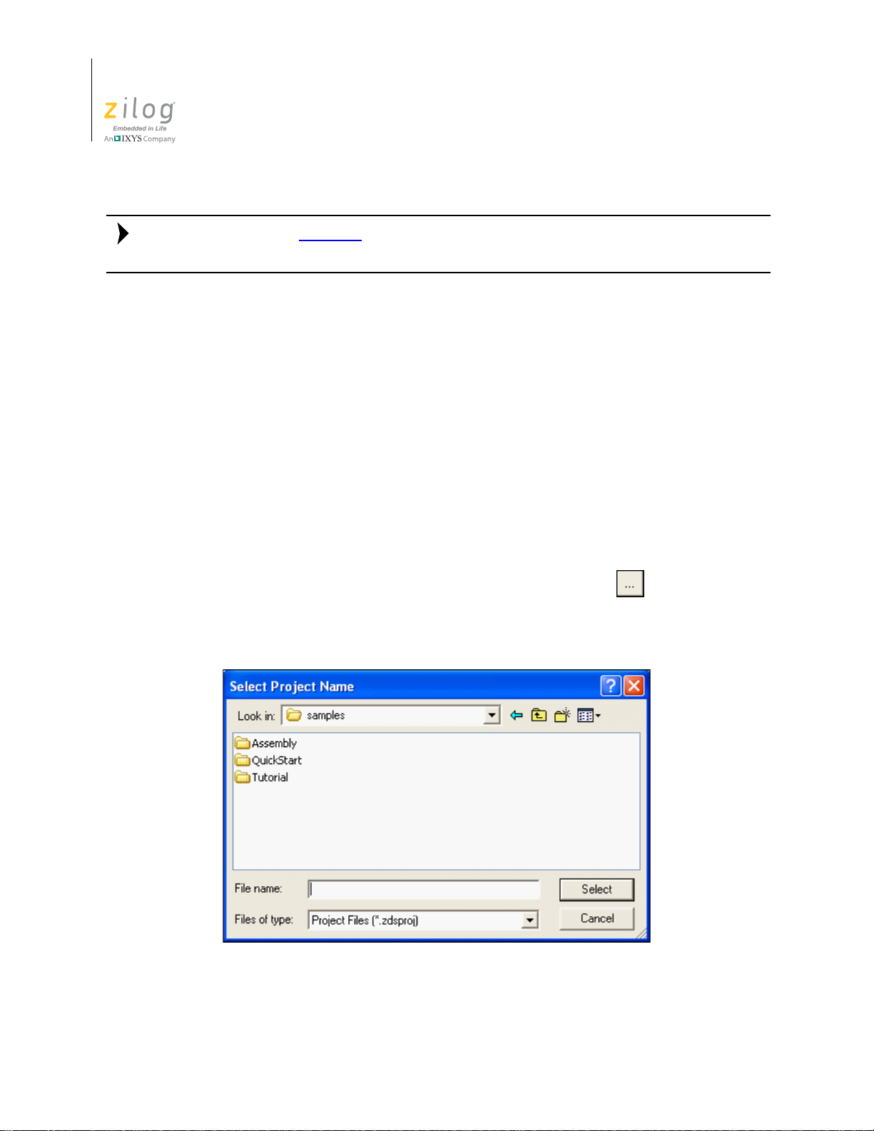
Zilog Developer Studio II – ZNEO™
Note:
User Manual
2
Be sure to read Menu Bar on page 31 to learn more about all of the dialog boxes and their
options discussed in this tour.
For the purpose of this tutorial, your ZNEO developer’s environment directory will be
referred to as <ZDS Installation Directory>, which equates to the following nomenclature:
<ZILOGINSTALL>\ZDSII_ZNEO_<version>\
where:
•
ZILOGINSTALL is the ZDS II installation directory. For example, the default installation directory is
•
version is the ZDS II version number. For example, version might be 4.11.0 or
5.0.0.
C:\Program Files\Zilog.
Create a New Project. Start the ZDS II program if it is not already running.
1. To create a new project, select
New Project from the File menu. The New Project
dialog box is displayed.
2. From the
directory in which to save your project. The
New Project dialog box, click the Browse button ( ) to navigate to a
Select Project Name dialog box is dis-
played; see Figure 1.
Figure 1. Select Project Name Dialog Box
Developer’s Environment Tutorial UM017105-0511
Page 31

Zilog Developer Studio II – ZNEO™
User Manual
3. Use the Look In drop-down menu to navigate to the directory in which you’ll save
your project. For this tutorial, Zilog recommends you place your project in the following directory:
3
<ZDS Installation Directory>
\samples\Tutorial
If Zilog Developer Studio was installed in the default directory, the actual filepath
would be:
C:\Program Files\Zilog\ZDSII_ZNEO_4.10.1\samples\Tutorial
4. In the File Name: field, enter sample as the name of your project.
The ZNEO developer’s environment creates a project file. By default, project files
have the
have to enter the extension
5. Click
6. Because the
.zdsproj extension (for example, <project name>.zdsproj). You do not
.zdsproj in this field. It is added automatically.
Select to return to the New Project dialog box.
sample project uses .c files, select Standard from the Project Type
drop-down menu.
7. In the
8. In the
9. In the
CPU Family drop-down menu, select Z16F_Series.
CPU drop-down menu, select Z16F2811AL.
Build Type drop-down menu, select Executable to build an application (see
Figure 2).
Figure 2. New Project Dialog Box
10. Click
Continue. The New Project Wizard dialog box is displayed (see Figure 3). It
allows you to modify the initial values for some of the project settings during the project creation process.
UM017105-0511 Developer’s Environment Tutorial
Page 32

Zilog Developer Studio II – ZNEO™
User Manual
4
Figure 3. New Project Wizard Dialog Box—Build Options Step
11. Accept the defaults by clicking Next. The Target and Debug Tool Selection step of
New Project Wizard dialog box is displayed; see Figure 4.
the
Developer’s Environment Tutorial UM017105-0511
Page 33

Zilog Developer Studio II – ZNEO™
User Manual
5
Figure 4. New Project Wizard Dialog Box—Target and Debug Tool Selection Step
12. Click Next to accept the defaults. The Target Memory Configuration step of the New
Project Wizard
dialog box is displayed; see Figure 5.
UM017105-0511 Developer’s Environment Tutorial
Page 34

Zilog Developer Studio II – ZNEO™
User Manual
6
Figure 5. New Project Wizard Dialog Box—Target Memory Configuration Step
13. Click Finish. ZDS II creates a new project named sample. Two empty folders, Stan-
Project Files and External Dependencies, are displayed in the Project Work-
dard
space
window on the left side of the integrated development environment (IDE).
Add a File to the Project
In this section, you add the main.c source file (provided) to the sample project.
1. From the
played; see Figure 6.
Project menu, select Add Files. The Add Files to Project dialog box is dis-
Developer’s Environment Tutorial UM017105-0511
Page 35

Zilog Developer Studio II – ZNEO™
User Manual
7
Figure 6. Add Files to Project Dialog Box
2. In the Add Files to Project dialog box, return to the tutorial directory by navigating to
<ZDS Installation Directory>
\samples\Tutorial
3. Select the main.c file and click Add. The main.c file is displayed under the Stan-
dard Project Files
folder in the Project Workspace window on the left side of the
IDE, as shown in Figure 7.
UM017105-0511 Developer’s Environment Tutorial
Page 36

Zilog Developer Studio II – ZNEO™
Note:
User Manual
8
Figure 7. Sample Project
To view a file in the Edit window during the tutorial, double-click the file in the Project
Workspace pane.
Set Up the Project
Before you save and build the sample project, check the settings in the Project Settings
dialog box.
1. From the
played. It provides various project configuration pages that can be accessed by selecting the page name in the pane on the left side of the dialog box. There are several
pages grouped together for the C compiler and Linker that allow you to set up subsettings for that tool. For more information about this topic, see Settings
Developer’s Environment Tutorial UM017105-0511
Project menu, select Settings. The Project Settings dialog box is dis-
on page 46.
Page 37

Zilog Developer Studio II – ZNEO™
User Manual
2. In the Configuration drop-down menu in the upper left corner of the Project Set-
tings
dialog box, make sure the Debug build configuration is selected, as shown in
Figure 8.
For your convenience, the Debug configuration is a predefined configuration of
defaults set to enable the debugging of program code. For more information about
project configurations such as adding your own configuration, see Set Active Config-
uration on page 83.
9
Figure 8. General Page of the Project Settings Dialog Box
3. Click the
UM017105-0511 Developer’s Environment Tutorial
Assembler page.
Page 38

Zilog Developer Studio II – ZNEO™
User Manual
10
4. Make sure that the Generate Assembly Listing Files (.lst) checkbox is selected, as
shown in Figure 9.
Figure 9. Assembler Page of the Project Settings Dialog Box
5. Click the
Developer’s Environment Tutorial UM017105-0511
Code Generation page.
Page 39

Zilog Developer Studio II – ZNEO™
User Manual
6. Select the Limit Optimizations for Easier Debugging checkbox, as shown in
Figure 10.
11
Figure 10. Code Generation Page of the Project Settings Dialog Box
7. Click the
UM017105-0511 Developer’s Environment Tutorial
Advanced page.
Page 40

Zilog Developer Studio II – ZNEO™
User Manual
12
8. Make certain the Generate Printfs Inline checkbox is selected, as shown in Figure 11.
Figure 11. Advan ced Page of the Project Settings Dialog Box
9. Click the
Developer’s Environment Tutorial UM017105-0511
Output page.
Page 41

Zilog Developer Studio II – ZNEO™
User Manual
10. Make sure that the IEEE 695 and Intel Hex32 - Records checkboxes are both
selected, as shown in Figure 12.
13
Figure 12. Output Page of the Project Settings Dialog Box
11. Click
OK to save all project settings. The Development Environment will prompt you
to build the project when changes are made to the project settings that would effect the
resulting build program. The message displays: “
changed since the last build. Would you like to rebuild the
affected files?
12. Click
Yes to build the project. The developer’s environment builds the sample proj-
”
The project settings have
ect.
UM017105-0511 Developer’s Environment Tutorial
Page 42

Zilog Developer Studio II – ZNEO™
User Manual
14
13. Observe the compilation process in the Build Output window, as shown in Figure 13.
When the
have successfully built the sample project and created a
Build completed message is displayed in the Build Output window, you
sample.lod file to debug.
Figure 13. Build Output Window
14. From the
Developer’s Environment Tutorial UM017105-0511
File menu, select Save Project.
Page 43

Zilog Developer Studio II – ZNEO™
Chapter 2. Using the Integrated Development Environment
This section discusses how to use the following integrated development environment
(IDE) elements.
•
Toolbars – see page 16
•
Windows – see page 23
•
Menu Bar – see page 31
•
Shortcut Keys – see page 105
User Manual
15
To effectively understand how to use the developer’s environment, be sure to go through
the Developer’s Environment Tutorial
After the discussion of the toolbars and windows, this section discusses the menu bar,
shown in Figure 14, from left to right—File, Edit, View, Project, Build, Debug, Tools,
Window, and Help—and the dialog boxes accessed from the menus. For example, the
Project Settings dialog box is discussed as a part of the Project menu section.
on page 1.
UM017105-0511 Using the Integrated Development Environment
Page 44

Zilog Developer Studio II – ZNEO™
User Manual
16
Figure 14. ZNEO Integrated Development Environment (IDE) Window
For a table of all of the shortcuts used in the ZNEO developer’s environment, see Shortcut
Keys on page 105.
Toolbars
The toolbars provide quick access to most features of the ZNEO developer’s environment.
You can use these buttons – even cue cards – to perform any task. As you move the mouse
pointer across the toolbars, the main function of each button is displayed in a pop-up dialog. Additionally, you can drag and move the toolbars to different areas on the screen.
The following toolbars are described in this section.
•
File Toolbar – see page 17
•
Build Toolbar – see page 18
Toolbars UM017105-0511
Page 45

•
Note:
Find Toolbar – see page 19
•
Command Processor Toolbar – see page 19
•
Debug Toolbar – see page 20
•
Debug Windows Toolbar – see page 22
For more information about debugging, see the Using the Debugger chapter on page 327.
File Toolbar
The File toolbar, shown in Figure 15, allows you to perform basic functions with your files
using a number of buttons, each of which is briefly described below.
Zilog Developer Studio II – ZNEO™
User Manual
17
Figure 15. The File Toolbar
New. Creates a new file.
Open. Allows you to open an existing file.
Save. Saves the active file.
Save All. Saves all open files and the currently loaded project.
Cut. Deletes selected text from the active file and puts it on the Windows clipboard.
Copy. Copies selected text from the active file and puts it on the Windows clipboard.
Paste. Pastes the current contents of the clipboard into the active file at the current cursor
position.
Delete. Deletes selected text from the active file.
Print. Prints the active file.
Workspace Window. Shows or hides the Project Workspace window.
Output Window. Shows or hides the Output window.
UM017105-0511 Toolbars
Page 46

Zilog Developer Studio II – ZNEO™
Note:
User Manual
18
Build Toolbar
The Build toolbar, shown in Figure 16, allows you to build your project, set breakpoints,
and select a project configuration with the following controls and buttons; a description of
each follows.
Select Build Configuration List Box. Lets you activate the build configuration for your
project. See the Set Active Configuration
Compile/Assemble File Button. Compiles or assembles the active source file.
Figure 16. The Build Toolbar
section on page 83 for more information.
Build Button. Builds your project by compiling and/or assembling any files that have
changed since the last build and then links the project.
Rebuild All Button. Rebuilds all files and links the project.
Stop Build Button. Stops a build in progress.
Connect to Target Button. Starts a debug session and initializes the communication to
the target hardware. Clicking this button does not download the software or reset to main.
Use this button to access target registers, memory , and so on, without loading new code or
to avoid overwriting the target’ s code with the same code. This button is not enabled when
the target is the simulator.
Download Code Button. Downloads the executable file for the currently open project to
the target for debugging. The button also initializes the communication to the target hardware if it has not been done yet. Use this button anytime during a debug session.
Using the Download Code button overwrites the current code on the target.
Reset Button. The Reset butto n resets the program counter to the beginnin g the program.
If not in Debug mode, a debug session is started. By default and if possible, clicking the
Reset button resets the program counter to symbol 'main'. If you deselect the Reset to
Symbol 'main' (Where Applicable)
checkbox on the Debugger tab of the Options dia-
log box (see page 102), the program counter resets to the first line of the program.
Go Button. The Go button executes project code from the current program counter. If not
in Debug mode when the button is clicked, a debug session is started .
Toolbars UM017105-0511
Page 47

Insert/Remove Breakpoint Button. The Insert/Remove Breakpoint button sets a new
breakpoint or removes an existing breakpoint in the active file at the line in which the cursor is. You can set a breakpoint in any line with a blue dot displayed to the left of the line
(shown in Debug mode only).
Enable/Disable Breakpoint Button. The En able/Disable Breakpoint button activates o r
deactivates an existing breakpoint at the line in which the cursor is. A red octagon indicates an enabled breakpoint; a white octagon indicates a disabled breakpoint.
Remove All Breakpoints Button. The Remove All Breakpoints button deletes all
breakpoints in the currently loaded project.
Find Toolbar
The Find toolbar, shown in Figure 17, provides access to text search functions using either
of two entry points, each of which is briefly described below.
Zilog Developer Studio II – ZNEO™
User Manual
19
Figure 17. The Find Toolbar
Find in Files Button. Opens the Find in Files dialog box, allowing you to search for text
in multiple files.
Find Field. To locate text in the active file, enter the text in the Find field and press the
Enter key . The search term is highlighted in the file. To search again, press the Enter key
again.
Command Processor Toolbar
The Command Processor toolbar, shown in Figure 18, allows you to execute IDE and
debugger commands using either of two entry points, each of which is briefly described
below.
Figure 18. The Command Processor Toolbar
See Supported Script File Commands
on page 364 for a list of supported commands.
UM017105-0511 Toolbars
Page 48

Zilog Developer Studio II – ZNEO™
Note:
User Manual
20
Run Command Button. Executes the command in the Command field. Output from the
execution of the command is displayed in the Command tab of the Output window.
Stop Command Button. Stops any commands currently running.
Command Field. The Command field allows you to enter a new command. Click the Run
Command
tion of the command is displayed in the
To modify the width of the Command field, perform the following brief procedure:
button or press the Enter key to execute the command. Output from the execu-
Command tab of the Output window.
1. Select
Customize from the Tools menu.
2. Click to set your cursor in the
Command field.
3. Use your mouse to select and drag the side of the hatched rectangle. The new size of
the
Command field is saved as a new project setting.
Debug Toolbar
The Debug toolbar, sh own in Figure 19 , allows you to perform debugging functions with
the following buttons:
Download Code Button. Downloads the executable file for the currently open project to
the target for debugging. The button also initializes the communication to the target hardware if it has not been done yet. Use this button anytime during a debug session.
Command field. A hatched rectangle highlights the
Figure 19. The Debug Toolbar
The current code on the target is overwritten.
Verify Download Button. Determines download correctness by comparing executable
file contents to target memory.
Reset Button. Resets the program counter to the beginning the program. If not in Debug
mode, a debug session is started. By default and if possible, clicking the
resets the program counter to symbol 'main'. If you deselect the
(Where Applicable)
checkbox on the Debugger tab of the Options dialog box (see
Reset to Symbol 'main'
Reset button
page 102), the program counter resets to the first line of the program.
Toolbars UM017105-0511
Page 49

Zilog Developer Studio II – ZNEO™
User Manual
Stop Debugging Button. Ends the current debug session. To stop program execution,
click the
Go Button. Executes project code from the current program counter. If not in Debug
Break button.
mode when the button is clicked, a debug session is started.
Run to Cursor Button. Executes the program code from the current program counter to
the line containing the cursor in the active file or the Disassembly window. The cursor
must be placed on a valid code line (a C source line with a blue dot displayed in the gutter
or any instruction line in the Disassembly window).
Break Button. Stops program execution at the current program counter.
Step Into Button. Executes one statement or instruction from the current program coun-
ter, following the execution into function calls. When complet e, the program counter
resides at the next program statement or instruction unless a function was entered, in
which case the program counter resides at the first statement or instruction in the function.
21
Step Over Button. Executes one statement or instruction from the current program coun-
ter without following the execution into function calls. When complete, the program counter resides at the next program statement or instruction.
Step Out Button. Executes the remaining statements or instructions in the current func-
tion and returns to the statement or instruction following the call to the current function.
Set Next Instruction Button. Sets the program counter to the line containing the cursor in
the active file or the Disassembly window.
Insert/Remove Breakpoint Button. Sets a new breakpoint or removes an existing break-
point at the line containing the cursor in the active file or the Disassembly window. A
breakpoint must be placed on a valid code line (a C source line with a blue dot displayed
in the gutter or any instruction line in the Disassembly window). For more information
about breakpoints, see the Using Breakpoints
Enable/Disable Breakpoint Button. Activates or deactivates the existing breakpoint at
section on page 343.
the line containing the cursor in the active file or the Disassembly window. A red octagon
indicates an enabled breakpoint; a white octagon indicates a disabled breakpoint. For more
information about breakpoints, see the Using Breakpoints
Disable All Breakpoints Button. Deact ivates al l breakpoints in the currently loaded proj-
ect. To remove breakpoints from your program, use the
section on page 343.
Remove All Breakpoints button.
Remove All Breakpoints Button. Deletes all breakpoints in the currently loaded project.
To deactivate breakpoints in your project, use the
UM017105-0511 Toolbars
Disable All Breakpoints button.
Page 50

Zilog Developer Studio II – ZNEO™
User Manual
22
Debug Windows Toolbar
The Debug Windows toolbar, shown in Figure 20, allows you to display a number of
Debug windows using a number of buttons, each of which is briefly described below.
Registers Window Button. Displays or hides the Registers window. This window is
described in the Registers Window
Special Function Registers Window Button. Opens one of ten Special Function Regis-
ters windows. This window is described in the Special Function Registers Wind ow
on page 330.
Figure 20. The Debug Windows Toolbar
section on page 329.
section
Clock Window Button. Displays or hides the Clock window. This window is described in
the Clock Window
Memory Window Button. Opens one of ten Memory windows. This window is described
in the Memory Window
Watch Window Button. Displays or hides the Watch window. This window is described
in the Watch Window
Locals Window Button. Displays or hides the Locals window. This window is described
in the Locals Window
Call Stack Window Button. Displays or hides the Call Stack window. This window is
described in the Call Stack Window
Symbols Window Button. Displays or hides the Symbols window. This window is
described in the Symbols Window
Disassembly Window Button. Displays or hides the Disassembly window. This window
is described in the Disassembly Window
Simulated UART Output Window Button. Displays or hides the Simulated UART Out-
put window . This window is described in the Simulated UAR T Output W indow
section on page 331.
section on page 331.
section on page 337.
section on page 339.
section on page 340.
section on page 340.
section on page 341.
section on
page 342.
Toolbars UM017105-0511
Page 51

Windows
Four ZDS II windows allow you to see various aspects of the tools while working with
your project. The first three of these windows, listed below, are described in this section;
the fourth is described in the chapter titled Using the Debugger.
•
Project Workspace Window – see page 23
•
Edit Window – see page 24
•
Output Windows – see page 29
•
Debug Windows – see page 329
Project Workspace Window
Zilog Developer Studio II – ZNEO™
User Manual
23
The Project Workspace window, located on the left side of the developer’s environment
(and shown in Figures 21 and 22), allows you to view your project files.
Figure 21. Project Workspace Window for Standard Projects
UM017105-0511 Windows
Page 52

Zilog Developer Studio II – ZNEO™
User Manual
24
Figure 22. Project Workspace Window for Assembly Only Projects
The Project W orkspace window provides access to related functions using context menus.
To access context menus, right-click a file or folder in the window. Depending on which
file or folder is highlighted, the context menu provides some or all of the following functions:
•
Dock the Project Workspace window
•
Hide the Project Workspace window
•
Add files to the project
•
Remove the highlighted file(s) from the project
•
Build project files or external dependencies
•
Build or compile the highlighted file
•
Undock the Project Workspace window, allowing it to float in the Edit window
Edit Window
This section covers the following topics:
•
Using the Context Menus – see page 25
•
Using Bookmarks – see page 26
The Edit window area, located on the right side of the developer’s environment (and
shown in Figure 23), allows you to edit the files in your project.
Windows UM017105-0511
Page 53

Zilog Developer Studio II – ZNEO™
User Manual
25
Figure 23. Edit Window
The Edit window supports the shortcuts listed in Table 1.
Table 1. Edit Shortcuts
Shortcuts Function
Ctrl + Z Undo
Ctrl + Y Redo
Ctrl + X Cut
Ctrl + C Copy
Ctrl + V Paste
Ctrl + F Find
F3 Repeat the previous search
Ctrl + G Go to
Ctrl + E
Ctrl + ]
Go to the matching { or } symbol. Place you r cursor at
the right or left of an opening or closing brace and
press Ctrl + E or Ctrl +] to move the cursor to the
matching opening or closing brace.
Using the Context Menus
There are two context menus in the Edit window, depending on where you click. When
you right-click in a file, the context menu allows you to do the following (depending on
whether any text is selected or you are running in Debug mode):
UM017105-0511 Windows
Page 54

Zilog Developer Studio II – ZNEO™
User Manual
26
•
Cut, copy, and paste text
•
Go to the Disassembly window
•
Show the program counter
•
Insert, edit, enable, disable, or remove breakpoints
•
Reset the debugger
•
Stop debugging
•
Start or continue running the program (Go)
•
Run to the cursor
•
Pause the debugging (Break)
•
Step into, over, or out of program instructions
•
Set the next instruction at the current line
•
Insert or remove bookmarks (for more, see the Using Bookmarks section on page 26)
When you right-click outside of all files, the context menu allows you to perform the following tasks:
•
Show or hide the Output windows, Project Workspace window, status bar, File toolbar, Build toolbar, Find toolbar, Command Processor toolbar, Debug toolbar, Debug
Windows toolbar
•
When in Workbook Mode, each open file features an associated tab along the bottom
of the Edit Windows area that allows users to toggle in and out of Workbook Mode.
•
Customize the buttons and toolbars
Using Bookmarks
A bookmark is a marker that identifies a position within a file. Bookmarks appear as cyan
boxes in the gutter portion (left) of the file window , as shown in Figure 24. The cursor can
be quickly positioned on a lines containing bookmarks.
Windows UM017105-0511
Page 55

Zilog Developer Studio II – ZNEO™
User Manual
27
Figure 24. Bookmark Example
T o insert a bookmark, position the cursor on the desired line of the active file and perform
one of the following actions:
•
Right-click in the Edit window and select Insert Bookmark from the resulting context
menu, shown in Figure 25.
•
Select Toggle Bookmark from the Edit menu.
•
Using your keyboard, enter Ctrl+M.
UM017105-0511 Windows
Page 56

Zilog Developer Studio II – ZNEO™
User Manual
28
Figure 25. Inserting a Bookmark
To remove a bookmark, position the cursor on the line of the active file containing the
bookmark to be removed and perform one of the following actions:
•
Right-click in the Edit window and select Remove Bookmark from the resulting context menu
•
Select Toggle Bookmark from the Edit menu
•
Using your keyboard, enter Ctrl+M
To remove all bookmarks in the active file, right-click in the Edit window and select
Remove Bookmarks from the resulting context menu.
To remove all bookmarks in the current project, select
Edit menu.
T o position the cursor at the next bookmark in the active file, perform one of the following
actions:
•
Right-click in the Edit window and select Next Bookmark from the resulting context
menu.
•
Select Next Bookmark from the Edit menu.
Remove All Bookmarks from the
•
Press the F2 key. The cursor moves forward through the file, starting at its current
position and beginning again when the end of file is reached, until a bookmark is
Windows UM017105-0511
Page 57

Zilog Developer Studio II – ZNEO™
User Manual
encountered. If no bookmarks are set in the active file, this function has no effect.
To position the cursor at the previous bookmark in the active file, perform one of the following actions:
•
Right-click in the Edit window and select Previous Bookmark from the resulting
context menu.
•
Select Previous Bookmark from the Edit menu.
•
Using your keyboard, enter Shift+F2. The cursor moves backwards through the file,
starting at its current position and starting again at the end of the file when the file
beginning is reached, until a bookmark is encountered. If no bookmarks are set in the
active file, this function has no effect.
29
Output Windows
The Output windows display output, errors, and other feedback from various components
of the Integrated Development Environment.
Select one of the tabs at the bottom of the Output window to select one of the Output windows, each of which is listed below and is described in this section.
•
Build Output Window – see page 29
•
Debug Output Window – see page 30
•
Find in Files Output Windows – see page 30
•
Messages Output Window – see page 31
•
Command Output Window – see page 31
To dock the Output window with another window, click and hold the window’s grip bar,
then move the window.
Double-click the window’s grip bar to cause it to become a floating window.
Double-click the floating window's title bar to change it to a dockable window.
Use the context menu to copy text from or to delete all text in the Output window.
Build Output Window. Holds all text messages generated by the compiler, assembler,
librarian, and linker, including error and warning messages; see Figure 26.
UM017105-0511 Windows
Page 58

Zilog Developer Studio II – ZNEO™
User Manual
30
Debug Output Window. Holds all text messages generated by the debugger while you are
in Debug Mode; see Figure 27.
Figure 26. Build Output Window
Figure 27. Debug Output Window
Find in Files Output Windows. The two Find in Files Output windows, shown in
Figures 28 and 29, display the results of the Find in Files command (available from the
Edit menu and the Find toolbar). The File in Files 2 window is used when the Output to
Pane 2
checkbox is selected in the Find in File dialog box (for more, see Find in Files on
page 41).
Figure 28. Find in Files Output Window
Windows UM017105-0511
Page 59

Zilog Developer Studio II – ZNEO™
User Manual
Figure 29. Find in Files 2 Output Window
Messages Output Window. Holds informational messages intended for the user. The
Messages Output window also displays the chip revision identifier (always
ZNEO) and the Smart Cable firmware version; see Figure 30.
0x0800 for
31
Command Output Window. Holds output from the execution of commands; see
Figure 31.
Menu Bar
The menu bar lists menu items used in the ZNEO developer’s environment. Clicking a
menu bar item displays a list of selection items. If an option on a menu item ends with an
ellipsis (...), selecting the option displays a dialog box. A number of items are displayed on
the menu bar; each is listed below and described in this section.
•
Figure 30. Messages Output Window
Figure 31. Command Output Window
File Menu – see page 32
UM017105-0511 Menu Bar
Page 60

Zilog Developer Studio II – ZNEO™
User Manual
32
•
Edit Menu – see page 40
•
Vi ew Menu – see page 44
•
Project Menu – see page 45
•
Build Menu – see page 83
•
Debug Menu – see page 86
•
Tools Menu – see page 87
•
Window Menu – see page 104
•
Help Menu – see page 105
File Menu
The File menu enables you to perform basic commands in the developer’s environment;
each of these file commands is briefly described in this section.
New File. Select New File from the File menu to create a new file in the Edit window.
Open File. Select Open File from the File menu to display the Open dialog box (see
Figure 32) which allows you to open the files for viewing and editing.
Figure 32. Open Dialog Box
Close File. Select Close File from the File menu to close the selected file.
New Project. To create a new project, perform the following brief procedure:
Menu Bar UM017105-0511
Page 61

Zilog Developer Studio II – ZNEO™
User Manual
1. Select New Project from the File menu. The New Project dialog box is displayed; see
Figure 33.
33
Figure 33. New Project Dialog Box
2. From the
New Project dialog box, click the Browse button ( ) to navigate to the
directory in which you’ll save your project. The
displayed; see Figure 34.
Select Project Name dialog box is
Figure 34. Select Project Name Dialog Box
3. In the
UM017105-0511 Menu Bar
File Name field, enter the name of your project. You do not have to enter the
.zdsproj extension; it is added automatically.
Page 62

Zilog Developer Studio II – ZNEO™
Note:
User Manual
34
The following characters cannot be used in a project name: ( ) $ , . - + [ ] ' &
4. Click
5. In the
6. In the
7. In the
8. In the
Select to return to the New Project dialog box.
Project Type field, select Standard for a project that uses .c files. Select
Assembly Only for a project that will include only assembly source code.
CPU Family drop-down menu, select Z16F_Series.
CPU drop-down menu, select a CPU.
Build Type drop-down menu, select Executable to build an application or
Static Library to build a static library. The default is Executable, which creates
select
an IEEE 695 executable format (
.lod). For more information, see the Project Set-
tings—Output Page section on page 72.
9. Click
Continue to change the default project settings using the New Project Wizard.
To accept all default settings, or to create static libraries, click
projects, the
bly-Only executable projects, continue to Step 11
New Project Wizard dialog box is displayed (see Figure 35). For Assem-
.
Finish. For Standard
Figure 35. New Project Wizard Dialog Box—Build Options
Menu Bar UM017105-0511
Page 63

Zilog Developer Studio II – ZNEO™
User Manual
10. Select whether your project is linked to the standard C start-up module, C run-time
library, and floating-point library; select a small or large memory model (see the
Memory Models
Target and Debug Tool Selection step of the New Project Wizard dialog box is dis-
section on page 161); and click Next. For executable projects, the
played; see Figure 36.
35
Figure 36. New Project Wizard Dialog Box—Target and Debug Tool Selection
11. Select the
Use Page Erase Before Flashing checkbox to configure the internal Flash
memory of the target hardware to be page-erased. If this checkbox is not selected, the
internal Flash is configured to be mass-erased.
12. Select the appropriate target from the
13. Click
Setup in the Target area. Refer to the Setup section on page 76 for details on
Target list box.
configuring a target.
14. Click
Add to create a new target (see Add on page 78) or click Copy to copy an exist-
ing target (see Copy
on page 79).
15. Select the appropriate debug tool and (if you have not selected the Simulator) click
Setup in the Debug Tool area. Refer to the Debug Tool section on page 80 for details
about the available debug tools and how to configure them.
16. Click
Next. The Target Memory Configuration step of the New Project Wizard dia-
log box is displayed; see Figure 37.
UM017105-0511 Menu Bar
Page 64

Zilog Developer Studio II – ZNEO™
User Manual
36
Figure 37. New Project Wizard Dialog Box—Target Memory Configuration
17. Enter the memory ranges appropriate for the target CPU.
18. Click
Open Project. To open an existing project, perform the following procedure:
1. Select
Finish.
Open Project from the File menu. The Open Project dialog box is displayed;
see Figure 38.
Menu Bar UM017105-0511
Page 65

Zilog Developer Studio II – ZNEO™
Note:
Note:
User Manual
37
Figure 38. Open Project Dialog Box
2. Use the Look In drop-down menu to navigate to the directory in which your project is
located.
3. Select the project to be opened, and click
Open to open your project.
To quickly open a project you were working in recently, see the Recent Projects section on
page 39.
Save Project. Select Save Project from the File menu to save the currently active proj-
ect. By default, project files and configuration information are saved in a file named
<project name>
.zdsproj. An alternate file extension is used if provided when the proj-
ect is created.
The <project name>.zdsproj.file contains all project data. If deleted, the project is no
longer available.
Save/Restore Project Workspace checkbox is selected (see the Options—General
If the
Tab section on page 96), a file named <project name>.wsp is also created or updated with
workspace information such as window locations and bookmark details. The
.wsp file
supplements the project information. If it is deleted, the last known workspace data is lost,
but this does not affect or harm the project.
UM017105-0511 Menu Bar
Page 66

Zilog Developer Studio II – ZNEO™
User Manual
38
Close Project. Select Close Project from the File menu to close the currently active proj-
ect.
Save. Select Save from the File menu to save the active file.
Save As
To save the active file with a new name, perform the following steps:
1. Select
Figure 39.
2. Use the
Save As from the File menu. The Save As dialog box is displayed; see
Figure 39. Save As Dialog Box
Save In drop-down menu to navigate to the appropriate directory.
3. Enter the new file name in the
4. Use the
5. Click
Save All. Select Save All from the File menu to save all open files and the currently
Save as Type drop-down menu to select the file type.
Save. A copy of the file is saved with the name you entered.
File Name field.
loaded project.
Print. Select Print from the File menu to print the active file.
Print Preview. Select Print Preview from the File menu to display the file you want to
print in Preview mode in a new window, as shown in the following brief procedure.
1. In the Edit window, highlight the file you want to show a Print Preview.
Menu Bar UM017105-0511
Page 67

Zilog Developer Studio II – ZNEO™
User Manual
2. From the File menu, select Print Preview. The file is displayed in a new window. As
shown in Figure 40,
main.c is in Print Preview mode.
39
Figure 40. Print Preview Window
3. To print the file, click
Print. To cancel the print preview, click Close. The file returns
to its edit mode in the Edit window.
Print Setup. Select Print Setup from the File menu to display the Print Setup dialog box,
which allows you to modify the printer’s default configuration, if desired, before you print
the file.
Recent Files. Select Recent Files from the File menu and then select a file from the
resulting submenu to open a recently opened file.
Recent Projects. Select Recent Projects from the File menu and then select a project
file from the resulting submenu to quickly open a recently opened project.
Exit. Select Exit from the File menu to exit the application.
UM017105-0511 Menu Bar
Page 68

Zilog Developer Studio II – ZNEO™
User Manual
40
Edit Menu
The Edit menu provides access to basic editing, text search, and breakpoint and bookmark
manipulation features. A number of edit menu options are available; each is described in
this section.
Undo. Undo the last edit made to the active file.
Redo. Redo the last edit made to the active file.
Cut. Delete selected text from the active file and place it on the Windows clipboard.
Copy. Copy selected text from the active file and put it on the Windows clipboard.
Paste. Paste the current contents of the clipboard into the active file at the current cursor
position.
Delete. Delete selected text from the active file.
Select All. Highlight all text in the active file.
Show Whitespaces. Select Show Whitespaces from the Edit menu to display all
whitespace characters such as spaces and tabs in the active file.
Find. To find text in the active file, observe the following procedure:
1. Select
Find from the Edit menu. The Find dialog box is displayed; see Figure 41.
Figure 41. Find Dialog Box
2. Enter a search string in the
What
drop-down menu. (By default, the currently selected text in a source file or the
text where your cursor is located in a source file is displayed in the
3. Select the
Match Whole Word Only checkbox if you want to ignore the search text
Find What field or select a recent entry from the Find
Find What field.)
when it occurs as part of longer words.
Menu Bar UM017105-0511
Page 69

Zilog Developer Studio II – ZNEO™
Note:
User Manual
4. Select the Match Case checkbox if you want the search to be case-sensitive.
41
5. Select the
6. Select the direction of the search with the
7. Click
Regular Expression checkbox if you want to use regular expressions.
Up or Down button.
Find Next to jump to the next occurrence of the search text or click Mark All to
insert a bookmark on each line containing the search text.
After clicking Find Next, the dialog box closes. You can press the F3 key or use the Find
Again
command to find the next occurrence of the search term without displaying the Find
dialog box again.
Find Again. Select Find Again from the Edit menu to continue searching in the active file
for text previously entered in the Find dialog box.
Find in Files. This function searches the contents of the files on disk; therefore, unsaved
data in open files is not searched.
To find text in multiple files, observe the following procedure:
1. Select
Find in Files from the Edit menu.
Find in Files dialog box is displayed; see Figure 42.
The
Figure 42. Find in Files Dialog Box
2. Enter a search string in the
menu. (If you select text in a source file before displaying the
is displayed in the
Find field.)
3. Select or enter the file type(s) to search for in the
Find field or select a recent entry from the Find drop-down
Find dialog box, the text
In File Types drop-down menu.
Separate multiple file types with semicolons.
UM017105-0511 Menu Bar
Page 70

Zilog Developer Studio II – ZNEO™
User Manual
42
4. Use the Browse button ( ) or the In Folder drop-down menu to select the location
of the files in which you plan to search.
5. Select the
Match Whole Word Only checkbox if you want to ignore the search text
when it occurs as part of longer words.
6. Select the
7. Select the
8. Select the
Match Case checkbox if you want the search to be case-sensitive.
Look in Subfolders checkbox if you want to search within subfolders.
Output to Pane 2 checkbox if you want the search results displayed in the
Find in Files 2 Output window. If this button is not selected, the search results are displayed in the Find in Files Output window.
9. Click
Replace. To find and replace text in the active file, observe the following procedure:
1. Select
Find to perform the search.
Replace from the Edit menu. The Replace dialog box is displayed; see
Figure 43.
Figure 43. Replace Dialog Box
2. Enter a search string in the
What
drop-down menu. (By default, the currently selected text in a source file or the
text where your cursor is located in a source file is displayed in the
3. Enter the replacement text in the
Replace With drop-down menu.
4. Select the
5. Select the
6. Select the
Match Case checkbox if you want the search to be case-sensitive.
Regular Expression checkbox if you want to use regular expressions.
Wrap Around Search checkbox to continue the search past the end (or
Find What field or select a recent entry from the Find
Find What field.)
Replace With field or select a recent entry from the
beginning) of the file until the current cursor position is reached.
7. Select the direction of the search with the
Menu Bar UM017105-0511
Up or Down button.
Page 71

Zilog Developer Studio II – ZNEO™
User Manual
8. Click Find Next to jump to the next occurrence of the search text, click Replace to
replace the highlighted text, or click
Replace All to automatically replace all instances
of the search text.
Go to Line. To position the cursor at a specific line in the active file, select Go to Line
from the
Enter the desired line number in the edit field and click
Edit menu to display the Go to Line Number dialog box, as shown in Figure 44.
Go To.
Figure 44. Go to Line Number Dialog Box
43
Manage Breakpoints
T o view, go to, enable, disable, or remove breakpoints in an active project, select Manage
Breakpoints
Figure 45, during Debug mode and Edit mode.
Breakpoints dialog box lists all existing breakpoints for the currently loaded project.
The
A check mark in the box to the left of the breakpoint description indicates that the breakpoint is enabled. Each of the buttons in this dialog box is described in this section.
from the Edit menu. You can access the Breakpoints dialog box, shown in
Figure 45. Breakpoints Dialog Box
Go to Code. T o move the cursor to a particular breakpo int you have set in a file, highlight
the breakpoint in the
Enable All. To make all listed breakpoints active, click Enable All. In dividual breakpoints
Breakpoints dialog box and click Go to Code.
can be enabled by clicking in the box to the left of the breakpoint description. Enabled
UM017105-0511 Menu Bar
Page 72

Zilog Developer Studio II – ZNEO™
Note:
Note:
Note:
User Manual
44
breakpoints are indicated by a check mark in the box to the left of the breakpoint description.
Disable All. To make all listed breakpoints inactive, click Disable All. Individual break-
points can be disabled by clicking in the box to the left of the breakpoint description. Disabled breakpoints are indicated by an empty box to the left of the breakpoint description.
Remove. To delete a particular breakpoint, highlight the breakpoint in the Breakpoints
dialog box and click
Remove All. To delete all of the listed breakpoints, click Remove All.
For more information about breakpoints, see the Using Breakpoints section on page 343.
Remove.
Toggle Bookmark. Select Toggle Bookmark from the Edit menu to insert a bookmark in
the active file for the line in which your cursor is located or to remove the bookmark for
the line in which your cursor is located.
Next Bookmark. Select Next Bookmark from the Edit menu to position the cursor at the
line in which the next bookmark in the active file is located.
The search for the next bookmark does not stop at the end of the file; the next bookmark
might be the first bookmark in the file.
Previous Bookmark. Select Previous Bookmark from the Edit menu to position the cur -
sor at the line in which the previous bookmark in the active file is located.
The search for the previous bookmark does not stop at the beginning of the file; the previous bookmark might be the last bookmark in the file.
Remove All Bookmarks. Select Remove All Bookmarks from the Edit menu to delete
all of the bookmarks in the currently loaded project.
View Menu
The View menu allows you to select the windows you want to display in the ZNE O de veloper’s environment. The
this section.
Menu Bar UM017105-0511
View menu contains four options, each of which is described in
Page 73

Zilog Developer Studio II – ZNEO™
User Manual
Debug Windows. When you are in Debug mode (running the debugger), you can select
any of the Debug windows. From the
appropriate Debug window. For more information about the Debug windows, see the
Debug Windows
The
Debug Windows submenu contains the following elements, each of which is
described in the chapter titled Using the Debugger.
•
Registers Window – see page 329
•
Special Function Registers Window – see page 330
•
Clock Window – see page 331
•
Memory Window – see page 331
•
Watch Window – see page 337
•
Locals Window – see page 339
section on page 329.
View menu, select Debug Windows and then the
45
•
Call Stack Window – see page 340
•
Symbols Window – see page 340
•
Disassembly Window – see page 341
•
Simulated UART Output Window – see page 342
Workspace. Display or hide the Project Workspace window.
Output. Display or hide the Output windows.
Status Bar. Display or hide the status bar, which resides beneath the Build Output win-
dow.
Project Menu
The Project menu allows you to add files to your project, set configurations for your project, and export a make file.
The Project menu contains the following options; the first three are described in this section.
•
Add Files – see page 46
•
Remove Selected File(s) – see page 46
•
Settings – see page 46
•
Export Makefile – see page 82
UM017105-0511 Menu Bar
Page 74

Zilog Developer Studio II – ZNEO™
User Manual
46
Add Files
To add files to your project, observe the following procedure:
1. From the
Project menu, select Add Files.The Add Files to Project dialog box is dis-
played; see Figure 46.
2. Use the
Look In drop-down menu to navigate to the appro priate directory in which the
files you want to add are saved.
Figure 46. Add Files to Project Dialog Box
3. Click the file you want to add or highlight multiple files by clicking on each file while
holding down the Shift key.
4. Click
Add to add these files to your project.
Remove Selected File(s)
Select this option from the Project menu to delete highlighted files in the Project Workspace window.
Settings
Select Settings from the Project menu to display the Project Settings dialog box, which
allows you to change your active configuration as well as set up your project.
Select the active configuration for the project in the
the upper left corner of the
Project Settings dialog box. For your convenience, the Debug
and Release configurations are predefined. For more information about project configura-
Menu Bar UM017105-0511
Configuration drop-down menu in
Page 75

Zilog Developer Studio II – ZNEO™
Note:
User Manual
tions, such as adding your own configuration, see the Set Active Configuration section on
page 83.
The Project Settings dialog box provides various project configuration pages that can be
accessed by selecting the page name in the pane on the left side of the dialog box. There
are several pages grouped together for the C (Compiler) and Linker that allow you to set
up subsettings for that tool. The pages for the C (Compiler) are Code Generation, Listing
Files, Preprocessor, and Advanced. The pages for the Linker are Commands, Objects and
Libraries, Address Spaces, Warnings, and Output.
If you change project settings that affect the build, the following message is displayed
when you click
have changed since the last build. Would you like to rebuild the
affected files?” Click Yes to save and then rebuild the project.
OK to exit the Project Settings dialog box: “The project settings
47
Each of the Project Settings pages is described in this section.
Project Settings—General Page. From the Project Settings dialog box, select the General
page. The options on the General page, shown in Figure 47, are described in this sec-
tion.
UM017105-0511 Menu Bar
Page 76

Zilog Developer Studio II – ZNEO™
Note:
User Manual
48
Figure 47. General Page of the Project Settings Dialog Box
CPU Family. Allows you to select the appropriate ZNEO family.
CPU. Defines which CPU you want to define for the ZNEO target. To change the CPU for
your project, select the appropriate CPU in the
CPU drop-down menu.
Selecting a CPU does not automatically select include files for your C or assembly source
code. Include files must be manually included in your code. Selecting a new CPU automatically updates the compiler preprocessor defines, assembler defines, and, where necessary,
the linker address space ranges and selected debugger target based on the selected CPU.
Show Warnings. This checkbox controls the display of warning messages during all
phases of the build. If the checkbox is enabled, warning messages from the assembler,
Menu Bar UM017105-0511
Page 77

Zilog Developer Studio II – ZNEO™
Note:
User Manual
compiler, librarian, and linker are displayed during the build. If the checkbox is disabled,
all these warnings are suppressed.
Generate Debug Information. This checkbox makes the build generate debug informa-
tion that can be used by the debugger to allow symbolic debugging. Enable this option if
you are planning to debug your code using the debugger. The checkbox enables debug
information in the assembler, compiler, and linker.
Enabling this option usually increases your overall code size by a moderate amount for
two reasons. First, if your code makes any calls to the C run-time libraries, the library version used is the one that was built using the
setting (see the Limit Optimizations for Easier Debugging
Limit Optimizations for Easier Debugging
section on page 52). Second,
the generated code sets up the stack frame for every function in your own program. Many
functions (those whose parameters and local variables are not too numerous and do not
have their addresses taken in your code) would not otherwise require a stack frame in the
ZNEO architecture, so the code for these functions is slightly smaller if this checkbox is
disabled.
49
The Generate Debug Information checkbox interact s with the Limit Optimizations for
Easier Debugging
checkbox on the Code Generation page (see the Limit Optimizations
for Easier Debugging section on page 52). When the Limit Optimizations for Easier
Debugging
can be performed. The
when the
Optimizations for Easier Debugging
session), the
checkbox is selected, debug information is always generated so th at debugging
Generate Debug Information checkbox is grayed out (disabled)
Limit Optimizations for Easier Debugging checkbox is selected. If the Limit
checkbox is later deselected (even in a later ZDS II
Generate Debug Information checkbox returns to the setting it had before
the Limit Optimizations for Easier Debugging checkbox was selected.
Ignore Case of Symbols. When the Ignore Case of Symbols checkbox is enabled, the
assembler and linker ignore the case of symbols when generating and linking code. This
checkbox is occasionally required when a project contains source files with case-insensitive labels. This checkbox is only available for Assembly Only projects with no C code.
Intermediate Files Directory. This directory specifies the location where all intermediate
files produced during the build will be located. These files include make files, object files,
and generated assembly source files and listings that are generated from C source code.
This field is provided primarily for the convenience of users who might want to delete
these files after building a project, while retaining the built executable and other, more
permanent files. Those files are placed into a separate directory specified in the
page (see the Project Settings—Output Page
section on page 72).
Output
Project Settings—Assembler Page. In the Project Settings dialog box, select the
Assembler
UM017105-0511 Menu Bar
page. The assembler uses the contents of the Assembler page to determine
Page 78

Zilog Developer Studio II – ZNEO™
User Manual
50
which options are to be applied to the files assembled. The options on the Assembler page,
shown in Figure 48, are each described in this section.
Figure 48. Assembler Page of the Project Settings Dialog Box
Includes. The Includes field allows you to specify the series of paths for the assembler to
use when searching for include files. The assembler first checks the current directory, then
the paths in the Includes field, and finally the default ZDS II include directories.
The ZDS II default include directory is:
<ZDS Installation Directory>
\include\std
where <ZDS Installation Directory> is the directory in which Zilo g Developer S tudi o was
installed. By default, this would be
sion>
, where <version> might be 4.11.0 or 5.0.0.
Defines.
The Defines field is equivalent to placing <symbol> EQU <value> in your assem-
C:\Program Files\Zilog\ZDSII_ZNEO_<ver-
bly source code. It is useful for conditionally built code. Each defined symbol must have a
Menu Bar UM017105-0511
Page 79

Zilog Developer Studio II – ZNEO™
User Manual
corresponding value (<name>=<value>). Multiple symbols can be defined and must be
separated by commas.
Generate Assembly Listing Files (.lst). When selected, the Generate Assembly Listing Files (.lst)
checkbox tells the assembler to create an assembly listing file for each
assembly source code module. This file displays the assembly code and directives, as well
as the hexadecimal addresses and op codes of the generated machine code. The assembly
listing files are saved in the directory specified by the Intermediate Files Directory field on
General page (see the Intermediate Files Directory section on page 49). By default,
the
this checkbox is selected.
Expand Macros. When selected, the Expand Macros checkbox tells the assembler to
expand macros in the assembly listing files.
Page Length. When the assembler generates the listing files, the Page Length field sets
the maximum number of lines between page breaks. The default is 56.
51
Page Width. When the assembler generates the listing files, the Page Width field sets the
maximum number of characters on a line. The default is 80; the maximum width is 132.
Project Settings—Code Generation Page. For Assembly Only projects, the Code Gen-
eration page is not available.
Figure 49 shows the Code Generation page.
UM017105-0511 Menu Bar
Page 80

Zilog Developer Studio II – ZNEO™
User Manual
52
Figure 49. Code Generation Page of the Project Settings Dialog Box
Limit Optimizations for Easier Debugging. Selecting this checkbox causes the compiler
to generate code in which certain optimizations are turned off. These optimizations can
cause confusion when debugging. For example, they might rearrange the order of instructions so that they are no longer exactly correlated with the order of source code statements
or remove code or variables that are not used. You can still use the debugger to debug your
code without selecting this checkbox, but it might difficult because of the changes that
these optimizations make in the assembly code generated by the compiler.
Selecting this checkbox makes it more straightforward to debug your code and interpret
what you see in the various Debug windows. However, selecting this checkbox also
causes a moderate increase in code size. Many users select this checkbox until they are
ready to go to production code and then deselect it.
Selecting this checkbox can also increase the data size required by your application. This
happens because this option turns off the use of register variables (see the Use Register
Variables section on page 57). The variables that are no longer stored in registers must
Menu Bar UM017105-0511
Page 81

Zilog Developer Studio II – ZNEO™
Note:
Note:
User Manual
instead be stored in memory (and on the stack if dynamic frames are in use), thereby
increasing the overall data storage requirements of your application. Usually this increase
is fairly small.
You can debug your application when this checkbox is deselected. The debugger continues to function normally, but debugging might be more confusing due to the factors
described earlier.
The Limit Optimizations for Easier Debugging checkbox interacts with the Generate
Debug Information checkbox (see the Generate Debug Information section on page 49).
Memory Model. The Memory Model drop-down list allows you to choose between the
two memory models supported by the ZNEO C-Compiler,
Small or Large. One funda-
mental difference between these models is that the small model can be implemented using
only ZNEO CPU’s internal Flash and RAM memory, but the large model requires the
presence of external RAM. Using the small model also results in more compact code and
often reduces the RAM requirements as well. However, the small model places constraints
on the data space size (not on the code space size) of your application. Some applications
might not be able to fit into the small model’s data space size; the large model is provided
to support such applications. See the Memory Models
section on page 161 for full details
of the memory models.
53
Project Settings—Listing Files Page. Figure 50 shows the Listing Files page.
For Assembly Only projects, the Listing Files page is not available.
UM017105-0511 Menu Bar
Page 82

Zilog Developer Studio II – ZNEO™
User Manual
54
Figure 50. (Listing Files Page of the Project Settings Dialog Box)
Generate C Listing Files (.lis). When selected, the Generate C Listing Files (.lis)
checkbox tells the compiler to create a listing file for each C source code file in your project. All source lines are duplicated in this file, as are any errors encountered by the compiler.
With Include Files. When this checkbox is selected, the compiler duplicates the contents
of all files included using the
#include preprocessor directive in the compiler listing file.
This can be helpful if there are errors in included files.
Generate Assembly Source Code. When this checkbox is selected, the compiler gener-
ates, for each C source code file, a corresponding file of assembler source code. In this file
(which is a legal assembly file that the assembler will accept), the C source code (commented out) is interleaved with the generated assembly code and the compiler-generated
assembly directives. This file is placed in the directory specified by the
Menu Bar UM017105-0511
Intermediate
Page 83

Zilog Developer Studio II – ZNEO™
Note:
User Manual
Files Directory checkbox in the General page. See the Intermediate Files Directory sec-
tion on page 49.
Generate Assembly Listing Files (.lst). When this checkbox is selected, the compiler
generates, for each C source code file, a corresponding assembly listing file. In this file,
the C source code is displayed, interleaved with the generated assembly code and the compiler-generated assembly directives. This file also displays the hexadecimal addresses and
op codes of the generated machine code. This file is placed in the directory specified by
the Intermediate Files Directory field in the
General page. See Intermediate Files Direc-
tory on page 49.
Project Settings—Preprocessor Page. Figure 51 shows the Preprocessor page.
For Assembly Only projects, the Preprocessor page is not available.
55
Figure 51. Preprocessor Page of the Project Settings Dialog Box
UM017105-0511 Menu Bar
Page 84

Zilog Developer Studio II – ZNEO™
Note:
User Manual
56
Preprocessor Definitions. The Preprocessor Definitions field is equivalent to placing
#define preprocessor directives before any lines of code in your program. It is useful for
conditionally compiling code. Do not put a space between the symbol\name and equal
sign; however, multiple symbols can be defined and must be separated by commas.
Standard Include Path. The Standard Include Path field allows you to specify the series
of paths for the compiler to use when searching for standard include files. Standard
include files are those included with the
more than one path is used, the paths are separated by semicolons (;). The compiler first
checks the current directory, then the paths in the Standard Include Path field. The default
standard includes are located in the following directories:
#include <file.h> preprocessor directive. If
<ZDS Installation Directory>
\include\std
<ZDS Installation Directory>\include\zilog
where <ZDS Installation Directory> is the directory in which Zilo g Developer S tudi o was
installed. By default, this would be
sion>
, where <version> might be 4.11.0 or 5.0.0.
User Include Path.
The User Include Path field allows you to specify the series of paths
C:\Program Files\Zilog\ZDSII_ZNEO_<ver-
for the compiler to use when searching for user include files. User include files are those
included with the
#include “file.h” in the compiler. If more than one path is used, the
paths are separated by semicolons (;). The compiler first checks the current directory, then
the paths in the User Include Path field.
Project Settings—Advanced Page. Figure 52 shows the Advanced page.
For Assembly Only projects, the Advanced page is not available.
Menu Bar UM017105-0511
Page 85

Zilog Developer Studio II – ZNEO™
User Manual
57
Figure 52. Advanced Page of the Project Settings Dialog Box
Use Register Variables. Selecting this checkbox allows the compiler to allocate local
variables in registers, rather than on the stack, when possible. This usually makes the
resulting code smaller and faster and, therefore, the default is that this checkbox is
enabled. However, in some applications, this checkbox might produce larger and slower
code when a function contains a large number of local variables.
The effect of this checkbox on overall program size and speed can only be assessed globally across the entire application, which the compiler cannot do automatically . Usually the
overall application size is smaller but there can be exceptions to that rule. For example, in
an application that contains 50 functions, this checkbox might make 2 functions larger and
the other 48 functions smaller. Also, if those two functions run slower with the checkbox
enabled but the others run faster, then whether the overall program speed is improved or
worsened depends on how much time the application spends in each function.
Because the effect of applying this option must be evaluated across an application as a
whole, user experimentation is required to test this for an individual application. Only a
UM017105-0511 Menu Bar
Page 86

Zilog Developer Studio II – ZNEO™
Notes:
User Manual
58
small fraction of applications benefit from deselecting the Use Register Variables checkbox.
The Use Register Variables checkbox interacts with the Limit Optimizations for Easier
Debugging
section on page 52). When the
selected, register variables are not used because they can cause confusion when debugging. The
Optimizations for Easier Debugging
for Easier Debugging
Use Register Variables checkbox returns to the setting it had before the Limit Optimizations for Easier Debugging
Using register variables can complicate debugging in at least two ways. One way is that
register variables are more likely to be optimized away by the compiler. If variables you
want to observe while debugging are being optimized away, you can usually prevent this
by any of the following actions:
checkbox on the C page (see the Limit Optimizations for Easier Debugging
Limit Optimizations for Easier Debugging check box is
Use Register Variables checkbox is disabled (grayed out) when the Limit
checkbox is selected. If the Limit Optimizations
checkbox is later deselected (even in a later ZDS II session), the
checkbox was selected.
•
Select the Limit Optimizations for Easier Debugging checkbox (see Limit Optimi-
zations for Easier Debugging on page 52)
•
Deselect the Use Register Variables checkbox
•
Rewrite your code so that the variables in question become global rather than local
The other way in which register variables can lead to confusing behavior when debugg ing
is when the same register is used to store different variables or temporary results at different times in the execution of your code. Because the debugger is not always aware of these
multiple uses, sometimes a value for a register variable might be shown in the Watch window that is not actually related to that variable at all.
Generate Printfs Inline. Normally, a call to printf() or sprintf() parses the format
string at run time to generate the required output. When the
Generate Printfs Inline
checkbox is selected, the format string is parsed at compile time, and direct inline calls to
the lower level helper functions are generated. This results in significantly smaller overall
code size because the top-level routines to parse a format string are not linked into the
project, and only those lower level routines that are actually used are linked in, rather than
every routine that could be used by a call to
calls
printf() or sprintf() is slightly larger than if the Generate Printfs Inline
printf. The code size of each routine that
checkbox is deselected, but this is more than offset by the significant reduction in the size
of library functions that are linked to your application.
T o reduce overall code size by selecting this checkbox, the following conditions are necessary:
Menu Bar UM017105-0511
Page 87

Zilog Developer Studio II – ZNEO™
User Manual
•
All calls to printf() and sprintf() must use string literals, rather than char*
variables, as parameters. For example, the following code allows the compiler to
reduce the code size:
sprintf ("Timer will be reset in %d seconds", reset_time);
But code such as the following results in larger code:
char * timerWarningMessage;
...
sprintf (timerWarningMessage, reset_time);
•
The functions vprintf() and vsprintf() cannot be used, even if the format string
is a string literal.
59
Generate Printfs Inline checkbox is selected and these conditions are not met, the
If the
compiler warns you that the code size cannot be reduced. In this case, the compiler generates correct code, and the execution is significantly faster than with normal
printf calls.
However, there is a net increase in code size because the generated inline calls to lower
level functions require more space with no compensating savings from removing the toplevel functions.
In addition, an application that makes over 100 separate calls of
might result in larger code size with the
Generate Printfs Inline checkbox selected
printf or sprintf
because of the cumulative effect of all of the inline calls. The compiler cannot warn about
this situation. If in doubt, simply compile the application both ways and compare the
resulting code sizes.
The
Generate Printfs Inline checkbox is selected by default.
Distinct Code Segment for Each Module. For most applications, the code segment for
each module compiled by the ZNEO compiler is named CODE. Later , i n the linker step of
the build process, the linker gathers all these small CODE segments into a single large
CODE segment and then places that segment in the appropriate address space, thus ensuring that all of the executable code is kept in a single contiguous block within a single
address space. However, some users might need a more complex configuration in which
particular code modules are put in different address spaces.
Such users can select the
Distinct Code Segment for Each Module checkbox to accom-
plish this purpose. When this checkbox is selected, the code segment for every module
receives a distinct name; for example, the code segment generated for the
module is given the name
myModule_TEXT. You can then add linker directives to the
myModule.c
linker command file to place selected modules in the appropriate address spaces. This
checkbox is deselected by default.
An example of the use of this feature is to place most of the application’s code in the usual
EROM address space (see the Project Settings—Address Spaces Page
UM017105-0511 Menu Bar
section on page 68
Page 88

Zilog Developer Studio II – ZNEO™
Note:
User Manual
60
for a discussion of the ZNEO address spaces) except for a particular module that is to be
run from the RAM (16-bit addressable RAM) space. See the Special Case: Partial Down-
load to RAM section on page 317 for an example of how to configure the linker command
file for this type of application.
It is the user’s responsibility to configure the linker command file properly when the Dis-
tinct Code Segment for Each Modu l e checkbox is selected.
Default Type of Char. The ANSI C Standard permits the compiler to regard char vari-
ables that are not otherwise qualified as either
discretion; the compiler is only required to consistently apply the choice to all such variables. So in the following declarations:
signed char sc;
unsigned char uc;
char cc;
signed or unsigned, at the compiler’s
the signedness of cc is left to the compiler. The Default Type of Char drop-down menu
allows you to make this decision. The selection,
char variables whose signedness is not explicitly declared. The default value for ZNEO is
Unsigned.
Project Settings—Librarian Page. This page is available for Static Library projects only.
Signed or Unsigned, is applied to all
To configure the librarian, observe the following procedure:
1. Select
Settings from the Project menu. The Project Settings dialog box is dis-
played.
2. Click the
3. Use the
Project Settings—Commands Page. Figure 56 shows the Commands page.
Librarian page.
Output File Name field to specify where your static library file is saved.
Menu Bar UM017105-0511
Page 89

Zilog Developer Studio II – ZNEO™
Note:
User Manual
61
Figure 53. (Commands Page of the Project Settings Dialog Box
Always Generate from Settings. When this button is selected, the linker command file is
generated afresh each time you build your project; the linker command file uses the project settings that are in effect at the time. This button is selected by default, which is the
preferred setting for most users. Selecting this button means that all changes you make in
your project, such as adding more files to the project or changing project settings, are automatically reflected in the linker command file that controls the final linking stage of the
build. If you do not want the linker command file generated each time your project builds,
select the
Use Existing button (see the Use Existing section on page 63).
Even though selecting Always Generate from Settings causes a new linker command file
to be generated when you build your project, any directives that you have specified in the
Additional Linker Directives dialog box are not erased or overridden.
UM017105-0511 Menu Bar
Page 90

Zilog Developer Studio II – ZNEO™
User Manual
62
Additional Directives. T o specify additional linker direct ives that are to be added to those
that the linker generates from your settings when the
button is selected, perform the following brief procedure.
Always Generate from Settings
1. Select the
2. Click
Edit. The Additional Linker Directives dialog box is displayed; see Figure 54.
Figure 54. Additional Linker Directives Dialog Box
Additional Directives checkbox.
3. Add new directives or edit existing directives.
4. Click
You can use the
OK.
Additional Directives checkbox if you must make some modifications or
additions to the settings that are automatically generated from your project settings, but
you still want all your project settings and newly added project files to take effect automatically on each new build.
You can add or edit your additional directives in the
Additional Linker Directives dialog
box. The manually inserted directives are always placed in the same place in your linker
command file: after most of the automatically generated directives and just before the final
directive that gives the name of the executable to be built and the modules to be included
in the build. This position makes your manually inserted directives override any conflicting directives that occur earlier in the file, so it allows you to override particular directives
that are autogenerated from the project settings. (The RANGE and ORDER linker directives are exceptions to this rule; they do not override earlier RANGE and ORDER directives but combine with them.) Use caution with this override capability because some of
the autogenerated directives might interact with other directives and because there is no
Menu Bar UM017105-0511
Page 91

Zilog Developer Studio II – ZNEO™
Note:
User Manual
visual indication to remind you that some of your project settings might not be fully taking
effect on later builds. If you need to create a complex linker command file, contact Zilog
Technical Support for assistance. See Zilog Technical Support
on page vii.
63
If you have selected the
Additional Directives checkbox, your manually inserted direc-
tives are not erased when you build your project. They are retained and re-inserted into the
same location in each newly created linker command file every time you build your project.
In earlier releases of ZDS II, it was necessary to manually insert a number of directives if
you had a C project and did not select the Standard C Start-up Module. This is no longer
necessary. The directives required to support a C start-up module are now always added to
the linker command file. The only time these directives are not added is if the project is an
Assembly Only project.
Use Existing. Observe the following procedure if you do not want a new linker command
file to be generated when you build your project:
1. Select the
2. Click the
Use Existing button.
Browse button ( ). The Select Linker Command File dialog box is dis-
played; see Figure 55.
Figure 55. Select Linker Command File Dialog Box
3. Use the
Look In drop-down menu to navigate to the linker command file that you
want to use.
UM017105-0511 Menu Bar
Page 92

Zilog Developer Studio II – ZNEO™
Note:
User Manual
64
4. Click Select.
The
Use Existing button is the alternative to the Always Generate from Settings button
(see the Always Generate from Settings
a new linker command file is not generated when you build your project. Instead, the
linker command file that you specify in this field is applied every time.
section on page 61). When this button is selected,
When the
all of the settings on the
Use Existing button is selected, many project settings are grayed out, including
Objects and Libraries page, Warnings page, and Output page.
These settings are disabled because when you have specified that an existing linker command file is to be used, those settings have no effect.
When the Use Existing button is selected, some other changes that you make in your project such as adding new files to the project also do not automatically take effect. To add new
files to the project, you must not only add them to the Project Workspace window (see the
Project Workspace Window
section on page 23), but you must also edit your linker command file to add the corresponding object modules to the list of linked modules at the end
of the linker command file.
Project Settings—Objects and Libraries Page. Figure 56 shows the Objects and
Libraries
page.
Menu Bar UM017105-0511
Page 93

Zilog Developer Studio II – ZNEO™
Note:
User Manual
65
Figure 56. Objects and Libraries Page of the Project Settings Dialog Box
Additional Object/Library Modules. Use the Additional Object/Library Modules field
to list additional object files and modules that you want linked with your application. You
do not need to list modules that are otherwise specified in your project, such as the object
modules of your source code files that appear in the Project Workspace window, the C
start-up module, and the Zilog default libraries listed in the
Objects and Libraries page.
Separate multiple module names with commas.
Modules listed in this field are linked before the Zilog default libraries. Therefore, if there
is a name conflict between symbols in one of these user-specified additional modules and
in a Zilog default library, the user-specified module takes precedence and its version of the
symbol is the one used in linking. You can take advantage of this to provide your own
replacement for one or more functions (for example, C run-time library functions) by compiling the function and then including the object module name in this field. This is an alter-
UM017105-0511 Menu Bar
Page 94

Zilog Developer Studio II – ZNEO™
User Manual
66
native to including the source code for the revised function explicitly in your project, which
would also override the function in the default run-time library.
C Start-up Module. The buttons and checkbox in this area (which are not available for
Assembly Only projects) control which start-up module is linked to your application. All
C programs require some initialization before the main function is called, which is typically done in a start-up module.
Standard. If the Standard button is selected, the precompiled start-up module shipped
with ZDS II is used. This standard start-up module performs a minimum amount of initialization to prepare the run-time environment as required by the ANSI C Standard and also
does some ZNEO-specific configuration such as interrupt vector table initialization. See
the Language Extensions
in the standard start-up module.
section on page 156 for details about the operations performed
Some of these steps carried out in the standard start-up module might not be required for
every application; therefore if code space is extremely tight, you might want to make some
judicious modifications to the start-up code. The source code for the start-up module is
located in the following file:
<ZDS Installation Directory>
\src\boot\common\startupX.asm
Here, <ZDS Installation Directory> is the directory in which Zilog Developer Studio was
installed. By default, this is
where <version> might be
model or
Included in Project. If the Included in Project button is selected, then the standard start-
l for the large model.
C:\Program Files\Zilog\ZDSII_ZNEO_<version>,
4.11.0 or 5.0.0. The X in startupX.asm is s for the small
up module is not linked to your application. In this case, you are responsible for including
suitable start-up code, either by including the source code in the Project Workspace window or by including a precompiled object module in the
ules
field. If you modify the standard start-up module to tailor it to your project, you must
select the
Use Standard Startup Linker Commands. If you select this checkbox, the same linker
Included in Project button for your changes to take effect.
Additional Object/Library Mod-
commands that support the standard start-up module are inserted into your linker command file, even though you have chosen to include your own, nonstandard start-up module
in the project. This option is usually helpful in getting your project properly configured
and initialized because all C start-up modules have to do most of the same tasks. Formerly,
these linker commands had to be inserted manually when you were not using the standard
startup.
The standard startup commands define a number of linker symbols that are used in the
standard start-up module for initializing the C run-time environment. You do not have to
refer to those symbols in your own start-up module, but many users will find it useful to
do so, especially since user-customized start-up modules are often derived from modifying
Menu Bar UM017105-0511
Page 95

Zilog Developer Studio II – ZNEO™
User Manual
the standard start-up module. There are also a few linker commands (such as CHANGE,
COPY, ORDER, and GROUP) that are used to configure your memory map. See the Linker
Commands section on page 260 for a description of these commands.
67
This option is only available when the
Included in Project button has been selected. The
default for newly created projects is that this checkbox, if available, is selected.
Use Default Libraries. These controls determine whether the available default libraries
that are shipped with Zilog Developer Studio II are to be linked with your application. For
ZNEO, there is essentially one available library, the C run-time library. The subset of the
run-time library dedicated to floating-point operations also has a separate control to allow
for special handling, as explained in the Floating Point Library
Use C Runtime Library. The C run-time library included with ZDS II provides selected
section on page 67.
functions and macros from the Standard C Library. Zilog’s version of the C run-time
library supports a subset of the Standard Library adapted for embedded applications, as
described more fully in the Using the ANSI C-Compiler
ect makes any calls to standard library functions, you must select the
Library
checkbox unless you prefer to provide your own code for all library functions that
you call. As noted in the Additional Object/Library Modules
chapter on page 155. If your proj-
Use C Runtime
section on page 65, you can
also set up your application to call a mixture of Zilog-provided functions and your own
customized library functions. To do so, select the
Use C Runtime Library checkbox. Calls
to standard library functions will then call the functions in the Zilog default library except
when your own customized versions exist.
Zilog’s version of the C run-time library is organized with a separate module for each
function or, in a few cases, for a few closely related functions. Therefore, the linker links
only those functions that you actually call in your code. This means that there is no unnecessary code size penalty when you select the
Use C Runtime Library checkbox; only
functions you call in your application are linked into your application.
Floating Point Library. The Floating Point Library drop-down menu allows you to
choose which version of the subset of the C run-time library that deals with the floatingpoint operations will be linked to your application:
•
Real
If you select
Real, the true floating-point functions are linked in, and you can perform
any floating-point operations you want in your code.
•
Dummy
If you select
Dummy, your application is linked with alternate versions that are
stubbed out and do not actually carry out any floating-point operations. This dummy
floating-point library has been developed to reduce code bloat caused by including
calls to
printf() and related functions such as sprintf(). Those functions in turn
make calls to floating-point functions for help with formatting floating-point expressions, but those calls are unnecessary unless you actually need to format floating-point
UM017105-0511 Menu Bar
Page 96

Zilog Developer Studio II – ZNEO™
Note:
User Manual
68
values. For most users, this problem has now been resolved by the Generate Printfs
Inline
sion). You only need to select the dummy floating-point library if you have to disable
the
operations. In that case, selecting
essarily.
•
None
checkbox (see the Generate Printfs Inline section on page 58 for a full discus-
Generate Printfs Inline checkbox and your application uses no floating-point
Dummy keeps your code size from bloating unnec-
If you can select
None, no floating-point functions are linked to your application at
all. This can be a way of ensuring that your code does not inadvertently make any
floating-point calls, because, if it does and this option is selected, you receive a warning message about an undefined symbol.
None of the libraries mentioned here are available for Assembly Only projects.
Project Settings—Address Spaces Page. Figure 57 shows the Address Spaces page.
Menu Bar UM017105-0511
Page 97

Zilog Developer Studio II – ZNEO™
User Manual
69
Figure 57. Address Spaces Page of the Project Settings Dialog Box
The memory range fields in the Address Spaces page allow you to inform ZDS II about the
amount and location of memory and I/O on your target system. The appropriate settings
for these fields depend on the CPU selection and target system design. ZDS II uses the
memory range settings to let you know when your code or data has grown beyond your
system’s capability. The system also uses memory ranges to automatically locate your
code or data.
See the Programmer’s Model of ZNEO Memory
section on page 303 for details about
address range functions. The ZDS II address ranges are:
Constant data (ROM). This range is typically 000000-001FFF for devices with 32 KB
of internal Flash,
000000-007FFF for devices with 128 KB of internal Flash. The lower boundary must be
00_000H. The upper boundary can be lower than 007FFF, but no higher.
UM017105-0511 Menu Bar
000000-003FFF for devices with 64 KB of internal Flash, and
Page 98

Zilog Developer Studio II – ZNEO™
Note:
User Manual
70
Program space (EROM). This range is typically 002000-007FFF for devices with 32
KB of internal Flash,
008000-01FFFF for devices with 128 KB of internal Flash. Specify a larger range only if
the target system provides external nonvolatile memory.
To use any external memory provided on the target system, you must configure the memory’s chip select in the Configure Target dialog box. See the Project Settings—Debugger
Page section on page 74.
Extended RAM (ERAM). Specify an ERAM range only if the target system provides
external random access memory below
ing address below
Internal RAM (RAM). This range is typically FFB700-FFBFFF for devices with 2 KB of
internal RAM or
name, this range can be expanded up to
external random access memory to fill out this address range. This field does not allow a
high RAM address boundary above
004000-00FFFF for devices with 64 KB of internal Flash, or
FF8000. The ERAM field does not accept a start-
800000.
FFB000-FFBFFF for devices with 4 KB of internal RAM. Despite its
FF8000-FFBFFF if the target system provides
FFBFFF.
Special Function Registers and IO (IODATA). Typically FFC000-FFFFFF. The micro-
controller reserves addresses
peripherals, and I/O ports. The ZDS II GUI expects addresses
FFE000 and above for its special function registers, on-chip
FFC000 to FFDFFF to be
used for external I/O (if any) on the target system.
Address range settings must not overlap. The following example presents the syntax used
in the address range fields:
<low address> – <high address> [,<low address> – <high address>] ...
where <low address> is the hexadecimal lower bound ary of a range and <high addr ess> is
the hexadecimal higher boundary of the range. The following are legal memory ranges:
0000-7fff
ffb000-ffbfff
008000-01ffff,050000-07ffff
The last example line shows how a comma is used to define holes in a memory range for
the linker. The linker does not place any code or data outside of the ranges specified here.
If your code or data cannot be placed within the ranges, a range error is generated.
The C-Compiler does not support gaps (holes) within the ERAM or RAM ranges.
Project Settings—Warnings Page. Figure 58 shows the Warnings page.
Menu Bar UM017105-0511
Page 99

Zilog Developer Studio II – ZNEO™
Note:
User Manual
71
Figure 58. Warnings Page of the Project Settings Dialog Box
Treat All Warnings as Fatal. When selected, this checkbox causes the linker to treat all
warning messages as fatal errors. When the checkbox is selected, the linker does not generate output file(s) if there are any warnings while linking. By default, this checkbox is
deselected, and the linker proceeds with generating output fi les even if there are warnings.
Selecting this checkbox displays any warning as an error, regardless of the state of the
Show Warnings checkbox in the General page (see the Show Warnings section on
page 48).
Treat Undefined Symbols as Fatal. When selected, this checkbox causes the linker to
treat undefined external symbol warnings as fatal errors. If this checkbox is selected, the
linker quits generating output files and terminates with an error message immediately if
the linker cannot resolve any undefined symbol. By default, this checkbox is selected
UM017105-0511 Menu Bar
Page 100

Zilog Developer Studio II – ZNEO™
Note:
User Manual
72
because a completely valid executable cannot be built when the program contains references to undefined external symbols. If this checkbox is deselected, the linker proceeds
with generating output files even if there are undefined symbols.
Selecting this checkbox displays any undefined external symbol warning as an error,
regardless of the state of the
Warnings section on page 48).
Warn on Segment Overlap. This checkbox enables or disables warnings when overlap
occurs while binding segments. By default, the checkbox is selected, which is the recommended setting for ZNEO. For some Zilog processors, benign segment overlaps can occur,
but, for the ZNEO, an overlap condition usually indicates an error in project configuration
that must be corrected. These errors in ZNEO can be caused either by user assembly code
that erroneously assigns two or more segments to overlapping address ranges or by user
code defining the same interrupt vector segment in two or more places.
Show Warnings checkbox in the General page (see the Show
Project Settings—Output Page. Figure 59 shows the Output page.
Menu Bar UM017105-0511
 Loading...