


Mounting- and operating instructions
Indoor Air Quality Guard LGW-13
CO2 Detector
ZILA GmbH
Neuer Friedberg 5
98527 Suhl
Tel.: +49 (0) 3681 867300
Fax: +49 (0) 03681 8673099
Web: www.zila.de
E-Mail: info@zila.de

CO2 Detektor Indoor Air Quality Guard LGW-13
Handbuch Version: DE_1606_TOLI_LGW13| 2
Table of contents
1. Scope of Delivery ................................... 2
2. Product description ............................... 2
3. Product features .................................... 2
3.1. Measuring Range ................................... 2
3.2. Functions ............................................... 2
3.3. Technical data ....................................... 2
3.4. Operating- and ambient conditions ....... 2
3.5. LED bar graph ........................................ 2
3.5.1. Internal LED ................................ 2
3.5.2. 10-digit LED CO2 display ............. 2
3.5.3. Relais LED.................................... 3
3.6. Standards and Guidelines ...................... 3
4. General safety instructions .................... 3
5. Mounting and Commissioning ............... 3
5.1. Installation position ............................... 3
5.2. Mounting options .................................. 3
5.2.1. Wall- and surface mounting ........ 3
5.3. tabletop unit with power supply ........... 4
6. Electrical connection ............................. 4
7. Connection of actuating elements
(examples) ............................................................. 5
7.1. 24VDC ventilation device ....................... 5
7.2. 24VDC electric window opener ............. 5
7.3. Ventilation devices with heat recovery . 5
8. Maintenance ......................................... 6
9. Support .................................................. 6
1. Scope of Delivery
Indoor Air Quality Guard LGW-13
Mounting material for wall-mounting
24V power supply (optional)
2. Product description
The LGW-13 is a versatile CO2 detector. The device
has an optical (LED) and acoustic warning signal
output (horn). Furthermore, a switching function
for common 24 Volt actuators is integrated for use
in industrial and domestic applications. The CO2
sensor is integrated in a compact housing made of
white polycarbonate (IP 20). The Sensor is based on
the optical measurement principle "NDIR" (nondispersive infrared absorption measurement).The
device is available in various measuring ranges from
0...1 Vol% available. The LGW-13 has an integrated
function monitoring and is maintenance-free.
3. Product features
3.1. Measuring Range
The device measures the CO2 concentration in the
ambient air in the range of 0...3000ppm (Standard).
Other measuring ranges up 1,0vol% are available on
request.
3.2. Functions
used as a CO2 sensor with 0-10V and 4-20mA
signal output
Suitable as a tabletop unit with a power
supply or for wall and surface mounting
Air quality traffic light with 10 LEDs
CO2 limit dependent switching function for
24 volt devices
Integrated alarm horn with 2 volume levels
3.3. Technical data
Dimension: (LxWxH): 120x80x35mm
Further technical specifications can be found in the
product-specific data sheet on our website
www.zila.de.
3.4. Operating- and ambient conditions
Operating temperature: -10...+50 °C
Storage temperature: -40...+100 °C
Relative humidity: 0..95 % (nicht
kondensierend)
Air pressure: 900...1100 hPa
3.5. LED bar graph
3.5.1. Internal LED
The LED in the top ventilation slots indicates the
status of the device and the internal monitoring
function. The monitoring function operates when
the device is turned on. If the LED is red, the device
is working properly. If an error occurs, the LED is off.
3.5.2. 10-digit LED CO2 display
The 10-digit display in the standard variant shows
the CO2 concentration in the range of 0...3000ppm
in 10 individual steps with 300ppm each. With
increasing CO2 concentration, more LEDs
permanently turn on from left to right. When
reducing the CO2 concentration in accordance with
the above steps, the corresponding LEDs turn off.

CO2 Detektor Indoor Air Quality Guard LGW-13
Handbuch Version: DE_1606_TOLI_LGW13| 3
3.5.3. Relays LED
The LED on the left side above the 10-digit display
indicates properly connected actuators and the
switching state. If the CO2 limit is exceeded and the
switching relay is triggered, the LED lights up yellow.
3.6. Standards and Guidelines
Der Indoor Air Quality Guard LGW-13
complies with the following
European standards and guidelines:
2014/30/EU (EMC Directive)
DIN EN 61000-3-3:2014-03
DIN EN 61000-3-2:2015-03
4. General safety instructions
Read safety instructions carefully
Keep the instruction
Mounting, commissioning and electrical
connection of the LGW-13 without power
supply may only be done by experts
Repairs may only be done by experts
The mentioned international protection
marking applies only when mounting
position and cable connection are correct
Only operate the device at a given voltage
Changes and modifications to the device are
forbidden and releases the ZILA GmbH of any
guarantee and liability
5. Mounting and
Commissioning
5.1. Installation position
For an optimal indoor air quality with the LGW-13 a
mounting height "at eye level" is recommended
depending on the application. This means that the
seat height of the people in rooms in offices with
sedentary activities is crucial for the mounting
height.
The proper mounting position is horizontally.
5.2. Mounting options
5.2.1. Wall- and surface mounting
You can mount the device on a wall in a few steps.
Note: The following pictures were
provided by the manufacturer of the
housing and illustrate the mounting of
the housing. Even though the actual
device deviates from this image, then the
procedure does not change during
mounting.
Step 1: Loosen the lower housing of the device from
the cover by opening the holder.
Step 2: Place the bottom case as straight as possible
to the wall in order to obtain a drilling template.
Drill the holes.
Step 3: Mount the bottom cover with the supplied
mounting materials on the wall.
Caution: When mounting on the
surface, the electrical wires must be
fitted through the hole in the middle
of the bottom case before firmly
mounting the base plate on the wall.

CO2 Detektor Indoor Air Quality Guard LGW-13
Handbuch Version: DE_1606_TOLI_LGW13| 4
Connect the electric wires according
to the circuit diagrams.
Step 4: Take the upper part of device and put it into
the holder of the wall-mounted base plate. Close
the device by pushing the top part. The LGW-13 is
completely assembled when it snaps into the
cradle.
Caution: electrical connection
exemplary! For detailed
information please refer to the
section commissioning or
connection of actuators
5.3. tabletop unit with power supply
Insofar as a power supply is in the delivery, connect
the power supply via the AC adapter jack on the left
side wall of the upper housing cover with the
device.
6. Electrical connection
The upper section of the circuit board is provided
for the electrical connection of peripherals such as
24-volt fans. Ventilation elements are connected via
the terminals shown below.
Seen on the screw
The type of signal output from the sensor are picked
up via the terminals X4, X5, X6 according to the next
picture. The terminal X1 is the power supply, as far
as the device is not powered via the power adapter.

CO2 Detektor Indoor Air Quality Guard LGW-13
Handbuch Version: DE_1606_TOLI_LGW13| 5
Seen on the screw
The jumpers are located on the circuit board next to
the PINs, which are inserted into the terminal on the
base plate during the closing of the housing.
7. Connection of actuating
elements (examples)
7.1. 24VDC ventilation device
Ventilator configuration:
JP1 and JP2 closed
Ventilator-Connect on X3-1 and
X3-3
7.2. 24VDC electric window opener
The relay of the LGW-13 switches the applied supply
voltage (+ 24VDC) of JP1 and the ground GND of JP2
alternately to the voltage input oft he window
opener.
Window opener configuration:
JP1 and JP2 closed
FOE-Connect on X2-1 and X3-1
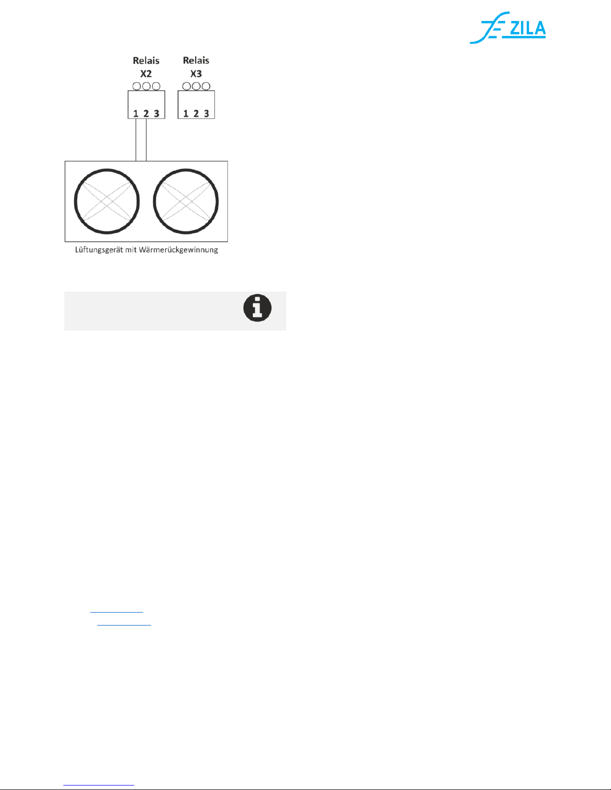
7.3. Ventilation devices with heat
recovery
The relay of the LGW-13 switches as a potential-free
contact with a ventilation device with heat
recovery. This ventilator normally consists of a
supply fan and an exhaust fan as well as an own
control for the ventilation stages. Optionally, these
fans have a connection for an external CO2 switch.
In this way, the ventilation unit is connected with
the Indoor Air Quality Guard LGW-13.
CO2 Detektor Indoor Air Quality Guard LGW-13
Handbuch Version: DE_1606_TOLI_LGW13| 6
Ventilation device with heat recovery
Configuration for heat recovery:
JP1 and JP2 open
WRG-Connect on X2-1 and X2-2
8. Maintenance
The Indoor Air Quality Guard LGW-13 is
maintenance free, thanks to NDIR technology.
According to the application, a regular calibration of
the device is recommened.
9. Support
Telephone: +49 (0) 3681 86 73 00
E-Mail: support@zila.de
ZILA GmbH
Neuer Friedberg 5
98527 Suhl
Tel.: +49 (0) 3681 867300
Fax: +49 (0) 03681 8673099
Web: www.zila.de
E-Mail: info@zila.de
 Loading...