

Page 1
COOKER HOOD
MANUAL
IT Manuale d’istallazione e uso 4
EN Use and installation manual 7
DE Bedienungs-und Montageanleitung 10
FR Manuel d’installation et d’utilisation 13
ES Manual de instalación y uso 16
RU Руководство по установке и использованию 19
Page 2
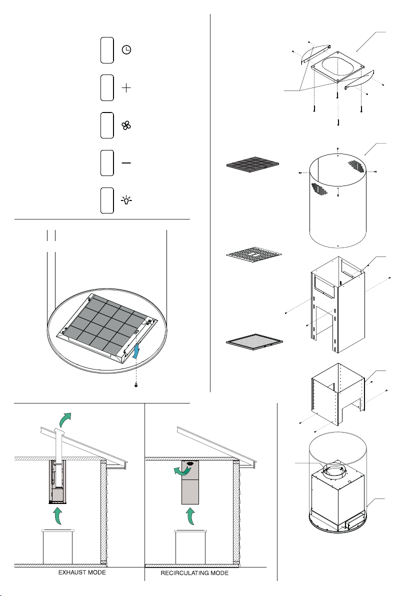
Fig.2
TYPE 1
Fig.4Fig.1
Ⓛ
optional
exhaust version
Ⓝ
optional
on request
Ⓩ
Ⓤ
Ⓔ
Ⓖ
Fig.3
660:1030
650:750
Ⓜ
Ⓗ
A B
Ⓨ
660:1030650:750
Ⓒ
Page 3
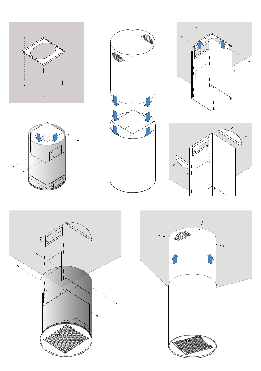
MONTAGGIO / ASSEMBLING / MONTAGE/ УСТАНОВКА
Fig.5
Fig.6
Fig.7
Fig.8
Fig.9
Fig.10 Fig.11
Page 4
ITALIANO
-
+
GENERALITA’
Leggere attentamente il contenuto del presente libretto in quanto fornisce importanti
indicazioni riguardanti la sicurezza di installazione, d’uso e di manutenzione. Conservare il libretto per ogni ulteriore consultazione.
ISTRUZIONI D’USO
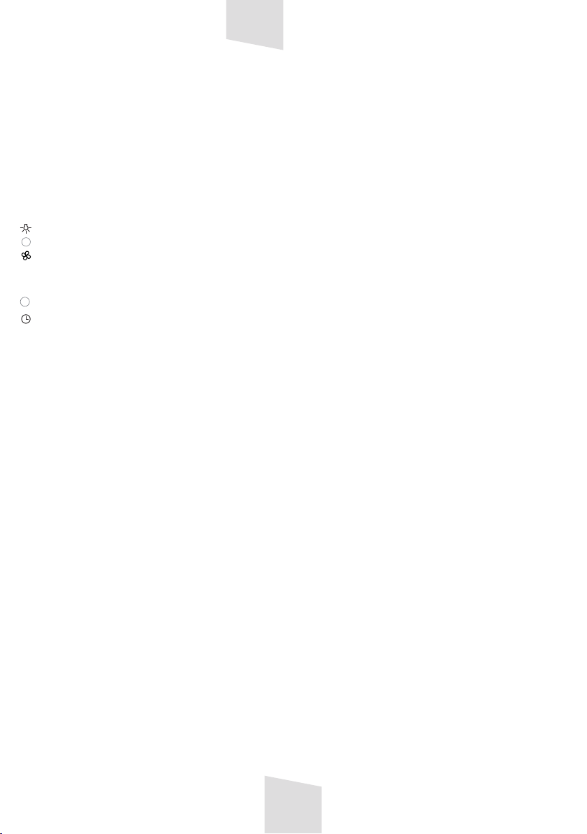
QUADRO COMANDI (Fig.1)
- Luce ON/OFF
-Riduce la velocità di aspirazione (da 4
a 1).
- ON/OFF. Accende la cappa in prima
velocità 1. Spegne la cappa a qualsiasi
velocità.
-Aumenta la velocità di aspirazione (da
1 a 4)
-TIMER - Attiva la funzione timer che
spegne automaticamente la cappa dopo
15 minuti.
Quando la velocità di aspirazione è
impostata su 4 il timer si attiva automaticamente. La velocità di aspirazione verrà
automaticamente impostata su 3 dopo 15
minuti
AVVERTENZE PER LA SICUREZZA
• Non fare cucine alla amma sotto la cappa.
• Nel caso in cui nella stanza vengano utilizzati simultaneamente sia la cappa che altri
apparecchi non alimentati da energia elettrica, bisogna provvedere ad areare il locale.
• Evitare fornelli accesi liberi (non utilizzati).
•Controllare costantemente i cibi fritti per
evitare che l’olio surriscaldato prenda fuoco.
•Non toccare le lampade dopo un uso protratto dell’apparecchio.
•Non cercare di controllare i ltri con la cappa in funzione.
• Limitare l’uso della cappa a ciò che è stata
progettata: abbattere gli odori di cucina.
Non utilizzarla per altri impieghi.
• Si consiglia di mettere in funzione la cappa
poco prima di procedere a qualsiasi operazione di cottura e di lasciarla in funzione
dopo la cottura per almeno 10 minuti e
IT
comunque no a quando ogni odore non sia
scomparso.
PULIZIA E MANUTENZIONE
•Il buon funzionamento della cappa è condizionato dall’assiduità con cui sono effettuate le operazioni di manutenzione, in modo
particolare, del ltro anti-grasso, e del ltro
al carbone attivo.
• Prima di procedere a qualsiasi operazione
di pulizia scollegare l’apparecchio dal colle-
gamento elettrico slando la spina o agendo
sull’ interruttore generale.
•Pulire frequentemente tutti i depositi sul
ventilatore e sulle altre superci, usando un
panno inumidito con alcool denaturato o
detersivi liquidi neutri non abrasivi.
FILTRI ANTIGRASSO METALLICI (Fig.4M)
I ltri antigrasso hanno il compito di trattenere le particelle grasse in sospensione
nell’aria, pertanto sono soggetti ad intasarsi in tempi variabili relativamente all’uso
dell’apparecchio.
In ogni caso, per prevenire il pericolo di
eventuali incendi, al massimo dopo 2 mesi
è necessario pulire i ltri eseguendo le seguenti operazioni:
• Togliere i ltri dalla cappa e lavarli con
una soluzione di acqua e detergente liquido
neutro, lasciando rinvenire lo sporco.
•Sciacquare abbondantemente con acqua
tiepida e lasciare asciugare.
I ltri possono essere lavati anche in lavastoviglie. Dopo alcuni lavaggi si possono
vericare delle alterazioni del colore. Questo
non dà diritto a reclamo per l’eventuale
sostituzione dei pannelli.
FILTRI AL CARBONE ATTIVO (Fig.4L)
I ltri al carbone attivo servono per depurare l’aria che verrà rimessa nell’ambiente.
La saturazione del carbone attivo dipende
dall’uso più o meno prolungato dell’apparecchio, dal tipo di cucina e dalla regolarità
con cui viene effettuata la pulizia del ltro
anti-grasso.
I ltri non sono lavabili o rigenerabili e
devono essere sostituiti ogni quattro mesi al
massimo.
Per il estrarre il ltro carbone è necessario:
4
Page 5

• smontare i ltri anti-grasso metallici
(Fig.4M).
•se presente, estrarre il pannello 'easy-clean'(Fig.4N) svitando le 4 viti.
• estrarre il ltro carbone svitando la relativa
vite (Fig.2)
ISTRUZIONI PER L’INSTALLAZIONE
L’apparecchio può essere utilizzato in 2
modalità:
•ASPIRANTE (Fig.3A): l'aria aspirata viene
puricata attraverso i ltri anti-grasso
metallici e canalizzata all'esterno attraverso
un tubo, tramite l’apposita condotta esterna
dell’abitazione.
•FILTRANTE (Fig.3B): l'aria aspirata viene
puricata attraverso i ltri anti-grasso e
un ltro a carbone attivo (venduto separatamente), l'aria viene inne rimessa
nell'ambiente interno attraverso le asole del
raccordo superiore.
A causa delle complessità dell’apparecchio si consiglia che l’installazione venga
effettuata da personale specializzato,
rispettando tutte le normative vigenti ed
in particolare quelle relative allo scarico
dell’aria da evacuare e al collegamento
elettrico. Il produttore declina qualsiasi
responsabilità per danni dovuti ad una
installazione non corretta o non conforme alle regole dell’arte.
IMPORTANTE
•L’apparecchio deve essere installato ad
un’altezza minima di 650 mm dai fornelli
elettrici, o 750 mm dai fornelli a gas o misti
(Fig.3).
•Se dovesse essere usato un tubo di connessione composto di due o più parti, la parte
superiore deve essere all’esterno di quella
inferiore.
•Non collegare lo scarico della cappa ad un
condotto in cui circoli aria calda o utilizzato per evacuare fumi di apparecchiature
alimentate da un’energia diversa da quella
elettrica.
•Nel caso in cui nella stanza vengano utilizzati sia la cappa che apparecchiature non
azionate da energia elettrica si deve prov-
vedere a creare una aerazione suciente
dell’ambiente.
•Per i vari montaggi utilizzare viti e tasselli
ad espansione idonei al tipo di muro (es.
cemento armato, cartongesso, ecc). Nel
caso in cui le viti e i tasselli siano forniti in
dotazione con il prodotto accertarsi che
siano idonei per il tipo di parete in cui deve
essere ssata la cappa.
COMPONENTI > vedi Fig.4
INSTALLAZIONE MODALITÀ ASPIRANTE
• Praticare i fori per il ssaggio della staffa Z
al sotto in corrispondenza del centro del
vostro piano di cottura. Bloccare la staffa Z
al sotto utilizzando 4 viti (Fig.5).
• Fissare la struttura telescopica inferiore H
al corpo della cappa C con 4 viti (Fig.6).
• Inlare il raccordo superiore E all’interno
del corpo della cappa C (Fig.7).
•Fissare la struttura telescopica superiore G
alla staffa Z con 4 viti (Fig.8).
•Fissare le 2 staffe laterali U alla struttura
telescopica superiore G con 2 viti su entram-
be i lati Fig.9).
•eseguire solo per versione aspirante
Collegare, mediante un tubo di raccordo,
la angia di Ø150 mm (Fig.4Y) al foro di
scarico.
Nel caso in cui l'appartamento sia dotato di
una condotta esterna per l'aria di Ø120 mm
applicare un raccordo di riduzione.
•Fissare la struttura telescopica superiore
G a quella inferiore H con 4 viti (Fig.10). Regolare l’altezza in maniera tale che la parte
inferiore della cappa si trovi ad una distanza
non inferiore a 650 mm dal piano di cottura
(Fig.3).
•Far scorrere il raccordo superiore E verso
l’alto e bloccarlo con 4 viti sui fori delle staffe U (Fig.11).
INSTALLAZIONE MODALITÀ FILTRANTE
Per trasformare la cappa da versione
aspirante a versione ltrante, è necessario
richiedere al vostro rivenditore il kit ltrante
e seguire le istruzioni di montaggio allegate
al kit.
COLLEGAMENTO ELETTRICO
Vericare che la tensione di rete sia adegua-
5
Page 6
ta a quella richiesta par l’alimentazione della
cappa come indicato sulla targhetta applicata all’interno dell’ apparecchio.
L’apparecchio è costruito in classe II, perciò
nessun cavo deve essere collegato alla presa
di terra. L’allacciamento alla rete elettrica
deve essere eseguito come segue:
MARRONE= L linea BLU= N neutro
Se non prevista, montare sul cavo una spina
normalizzata per il carico indicato nella
etichetta caratteristiche.
Se provvista di spina, la cappa deve essere installata in modo tale che la spina sia
accessibile. Nel caso di collegamento diretto
alla rete elettrica è necessario interporre tra
l’apparecchio e la rete un interruttore omnipolare con apertura minima tra i contatti
3 mm, dimensionato al carico e rispondente
alle norme vigenti.
CONTROLLO FUNZIONALE
Vericare l’accensione del motore a tutte le
velocità e l’illuminazione.
DISMISSIONE DEGLI ELETTRODOMESTICI
La direttiva Europea 2002/96/CE sui
riuti di apparecchiature elettriche
ed elettroniche (RAEE), prevede
che gli elettrodomestici non
debbano essere smaltiti nel
normale usso dei riuti solidi urbani. Gli
apparecchi dismessi devono essere raccolti
separatamente per ottimizzare il tasso di
recupero e riciclaggio dei materiali che li
compongono ed impedire potenziali danni
per la salute e l’ambiente. Il simbolo del
cestino barrato è riportato su tutti i prodotti
per ricordare gli obblighi di raccolta separata. Per ulteriori informazioni, sulla corretta
dismissione degli elettrodomestici, i detentori potranno rivolgersi al servizio pubblico
preposto o ai rivenditori.
SI DECLINA OGNI RESPONSABILITÀ PER
EVENTUALI DANNI PROVOCATI DALLA
INOSSERVANZA DELLE SUDDETTE AVVERTENZE. LA GARANZIA NON E’ VALIDA NEL
CASO DI DANNI DERIVANTI DALLA INOSSERVANZA DELLE SUDDETTE AVVERTENZE.
6
Page 7
ENGLISH
-
+
GENERAL INSTRUCTIONS
Carefully read the following important information regarding installation safety and
maintenance. Keep this information booklet
accessible for further consultations.
USE INSTRUCTIONS
CONTROL PANEL (Fig.1)
- Light ON/OFF
-Reduce fan speed (4 to 1)
-ON/OFF.
Switch on the cooker hood at speed 1.
Switch off the cooker hood at any speed.
-Increase fan speed (1 to 4)
-TIMER - Activate the timer function.
The timer will automatically switch off
the fan after 15 minutes.
When the fan speed is set to 4 the timer
activates automatically. After 15 minutes of activity the fan will automatically
switch to speed 3.
SAFETY INSTRUCTIONS
In certain circumstances electrical ap-
pliances may be a danger hazard.
• The hood has been designed to remove
the kitchen smells; any other additional use
shall be regarded as non-intended.
• Aerate the room if other appliances that
are not supplied by electrical power are
being used while the hood is on.
• Do not leave the cooker on if it is not being
used.
•Do not ambé food directly under the
cooker hood to prevent the grease lter
catching re due to ames.
•Constantly check food frying to avoid
that the overheated oil may become a re
hazard.
•Do not check the status of the lters while
the cooker hood is operating.
•Do not touch the light bulbs after appliance
use.
EN
USE AND MAINTENANCE
It is recommended to switch on the appliance before cooking. It is also recommended
to leave the appliance in operation for 10
minutes after cooking is terminated in order
to completely eliminate cooking vapours
and odours.
The proper function of the cooker hood is
conditioned by the regularity of the maintenance operations, in particular, the active
carbon lter.
Clean the fan and other surfaces of the
cooker hood regularly using a cloth moistened with denatured alcohol or non abrasive
liquid detergent.
WARNING: unplug the appliance or
switch off the circuit breaker before
carrying out maintenance operations.
METAL ANTI-GREASE FILTERS (Fig.4M)
The metal anti-grease lters capture the
grease particles of the vapours that develop
during cooking, therefore they are subject
to clogging according to the frequency of
the use of the appliance.
In order to prevent re hazard, it is recommendable to clean the lter every 2 months
by carrying out the following instructions:
• Remove the lters from the cooker hood
and wash them in a solution of water and
neutral liquid detergent, leaving to soak.
• Rinse thoroughly with warm water and
leave to dry.
The lters may also be washed in a dishwasher.
The aluminium panels may alter in colour
after several washes. This is not cause for
customer complaint nor replacement of
panels.
ACTIVATED CARBON FILTERS (Fig.4L)
The activated carbon lters purify the
kitchen vapours, the air is then conveyed
back into the kitchen.
The saturation of the active carbon lter
depends on the frequency of use of the
appliance, by the type of cooking and the
regularity of cleaning the anti-grease lters.
7
Page 8

The lters are not washable nor re-useable
and must be replaced at maximum every
four months.
To assemble the carbon lter it is necessary
to:
- remove the metal anti-grease lters
(Fig.4M)
- if present, extract the 'easy-clean' panel
(Fig.4N) by unscrewing the 4 screws.
- remove the carbon lter unscrewing the
screw (Fig.2)
INSTALLING INSTRUCTIONS
This hood has been arranged to be installed
above a cooktop. It can be used in 2 ways:
•EXHAUST MODE (Fig.3A): the kitcken va-
pours are puried by the metal anti-grease
lters and carried outside through a ducting
system.
•RECIRCULATING MODE (Fig.3B): the
kitcken vapours are puried by the metal
anti-grease lters and an activated carbon
lter (sold separately), then conveyed back
into the kitchen through the eyelets impressed on the upper chimney.
We suggest to have installation carried out
by qualied personnel, in compliance with
all the current regulations and in particular
with the ones concerning air exhaust and
electrical connection.The manufacturer
cannot be held liable for damages caused
by improper installation or if it has not been
carried out according to the state-of-the-art.
IMPORTANT
•The appliance must be installed at a minimum height of 650 mm from an electric cooker stove, or 750 mm from gas or combined
cooker stoves (Fig.3).
•If a connection tube composed of two parts
is used, the upper part must be placed outside the lower part.
•Do not connect the cooker hood exhaust to
the same conductor used to circulate hot air
or for evacuating fumes from other appliances generated by other than an electrical
source.
•Take care when the cooker hood is opera-
ting simultaneously with an open replace
or burner that depend on the air in the
environment and are supplied by other than
electrical energy, as the cooker hood removes the air from the environment which a
burner or replace need for combustion.
•Provide adequate ventilation in the environment for a safe operation of the cooker
hood.
•Follow the local laws applicable for external
air evacuation.
•Use screws and screw anchors suitable for
wall (e.g. reinforced cement, plasterboard)
for the mounting of the cooker hood. Where
screws and screw anchors are supplied
ensure that they are suitable for the type
of wall where the cooker hood is to be
mounted.
COMPONENTS > see Fig.4
EXHAUST MODE INSTALLATION
• Drill the holes of the bracket Z to the
ceiling at the center of your cooktop. Lock
the Z bracket to the ceiling using 4 screws
(Fig. 5).
• Attach the telescopic lower H of the hood
C to the body with 4 screws (Fig. 6)
• Thread the upper connection E and within
the body of the hood C (Fig. 7)
• Attach the telescopic bracket G to the
bracket Z with 4 screws (Fig. 8)
• Attach the two side brackets U to the
telescopic structure than G with 2 screws on
both sides (Fig. 9)
• carry out for exhaust mode only
Connect through a connecting tube, the
ange of Ø 150 mm (Fig. 4Y) to the drain
hole. In the event that the apartment is
equipped with a pipe outside air connection
of Ø 210mm apply a reduction.
•Attach the telescope G to the lower H with
4 screws (Fig. 10). Adjust the height so that
the underside of the hood is at a distance
of not less than 650 mm from the cooking
surface (Fig. 3).
•Slide the upper connection and up and
secure with 4 screws in the holes of the
brackets U (Fig. 11).
RECIRCULATING MODE ISTALLATION
In order to transform your cooker hood
from the exhaust version to the recirculating version, ask your local retailer for the
8
Page 9

recircultating kit and then carry out the
enclosed installing instructions.
ELECTRICAL CONNECTION
The appliance has been manufactured as a
class II, therefore no earth cable is necessary. The connection to the mains is carried
out as follows:
BROWN = L line BLUE = N neutral
If not provided, connect a plug for the electrical load indicated on the description label.
Where a plug is provided, the cooker hood
must be installed in order that the plug is
easily accessible. An omnipolar switch with
a minimum aperture of 3 mm between
contacts, in line with the electrical load and
local standards, must be placed between
the appliance and the network in the case of
direct connection to the electrical network.
OPERATING CHECKS
Check lights and motor start-up on all
speeds.
DISPOSAL OF OLD ELECTRICAL APPLIANCES
The European Directive 2002/96/EC
on Waste Electrical and Electronic
Equipment (WEEE), requires that old
household electrical appliances
must not be disposed of in the
normal unsorted municipal waste stream. Old
appliances must be collected separately in
order to optimise the recovery and recycling
of the materials they contain and reduce the
impact on human health and the environment. The crossed-out dustbin symbol on
the product reminds you of your obligation
regarding separated waste collection. Consumers should contact their local public service
or their local dealer for more information on
the correct disposal of exhausted household
appliances.
THE MANUFACTURER DECLINES ALL RESPONSIBILITY FOR EVENTUAL DAMAGES
CAUSED BY BREAKING THE ABOVE WARNINGS. THE WARRANTY IS NOT VALID IN
THE CASE OF DAMAGE CAUSED BY FAILURE
TO COMPLY WITH THE ABOVE WARNINGS.
9
Page 10

DEUTSCH
-
+
ALLGEMEINES
Lesen Sie diese Bedienungsanleitung
bitte aufmerksam durch, da sie wichtige
Sicherheitshinweise hinsichtlich der Instal-
lation, dem Gebrauch und der Wartung des
Gerätes enthält. Bewahren Sie die Bedie-
nungsanleitung für mögliche zukünftige
Fragen oder Probleme bitte auf.
BEDIENUNG UND WARTUNG
STEUERPULT (Abb.1)
- LICHT EIN/AUS
-Verringert die Ansauggeschwindigkeit
(von 4 auf 1)
-ON/OFF Schaltet die Abzugshaube in
Stufe ein. Schaltet sie aus, egal in welcher
Stufe.
-Erhöht die Ansauggeschwindigkeit
(von 1 auf 4)
-TIMER - Aktiviert die Timer-Funktion,
die die Abzugshaube automatisch nach
15 Minuten abschaltet. Ist die Ansaug-
geschwindigkeit auf Stufe 4 eingestellt,
wird der Timer automatisch aktiviert. Die
Ansauggeschwindigkeit wird nach 15 Minuten automatisch auf Stufe 3 zurückgeschaltet.
VORSICHT!
Elektrogeräte können unter gewissen
Umständen gefährlich sein!
•Kontrollieren Sie niemals die Filter, wenn
die Dunstabzugshaube in Betrieb ist.
•Fassen Sie die Lämpchen nach längerem
Betrieb der Dunstabzugshaube nicht an.
•Es ist verboten, unter der Dunstabzugshau-
be Speisen zu ambieren.
•Offenes Feuer ist unbedingt zu vermeiden,
da dieses die Filter beschädigen und einen
Brand verursachen kann.
•Kontrollieren Sie beim Frittieren die Speisen
ständig, um eine Entzündung des Öls zu
vermeiden.
•Vor jeglichen Wartungsarbeiten unbedingt
den Netzstecker aus der Steckdose entfernen.
DE
BEDIENUNG
Es wird empfohlen, die Dunstabzugshaube
vor eventueller Zubereitung der Speisen
einzuschalten.
Es wird weiterhin empfohlen, das Gerät
nach Beendigung des Kochvorganges noch
10 Minuten weiterlaufen zu lassen, um die
vollständige Entlüftung der Kochdämpfe zu
gewährleisten.
Das einwandfreie Funktionieren der Dun-
stabzugshaube hängt entscheidend von der
Sorgfalt ab, mit der die Wartungsarbeiten
durchgeführt werden, insbesondere die des
Fettlters und die des Aktivkohlelters.
FETTFILTER AUS METALL (Abb.4M)
Die Fettlter haben die Aufgabe, die Fettpartikel in der Luft zu binden; die Sättigung der
Filter hängt daher von der Häugkeit ab, mit
der die Dunstabzugshaube betrieben wird.
Um eine mögliche Brandgefahr zu verhindern, muss der Filter auf jeden Fall spätestens alle zwei Monate wie folgt gereinigt
werden:
•Entnehmen Sie die Filter aus der Dunstabzugshaube und waschen Sie sie mit
einem Gemisch aus Wasser und üssigem
Neutralreiniger.
•Wenn notwenig, lassen Sie die Verschmutzungen kurz einweichen.
•Gründlich mit lauwarmem Wasser abspülen
und abtrocknen lassen. Sie können die Filter
auch in der Geschirrspülmaschine reinigen.
Nach mehrmaligem Waschen der Alumi-
niumlter können Farbveränderungen
auftreten.
Daraus resultiert jedoch kein Anspruch auf
einen kostenlosen Ersatz dieser Teile des
Geräts.
AKTIVKOHLEFILTER (Abb.4L)
(für Umluftversion) einzeln verkäuich
Die Aktivkohlelter dienen dazu, die
Luft zu reinigen, die wieder in den Raum
zurückgeführt wird. Diese Filter sind weder
waschbar noch wieder verwertbar und müssen spätestens alle vier Monate ausgewechselt werden.
Die Sättigung der Aktivkohle ist von der
mehr oder weniger langen Benutzung der
Küchenhaube abhängig, sowie von der
10
Page 11

Art der zubereiteten Speisen und von der
Regelmäßigkeit, mit welcher die Fettlter
gereinigt werden.
Zur Montage des Kohlelters ist Folgendes
erforderlich:
•Die metallenen Fettlter abmontieren
(Abb.4M).
•Die „Easy-clean“- Platte herausnehmen,
wenn Ihre Version der Haube sie enthält
(Abb.4N), indem man die Schrauben löst.
•Kohlelter bei der entsprechenden Schraube (Abb.2) eindrehen bis zum Anschlag.
INSTALLATION
Das Gerät wurde als Dunstabzugshaube
mit Abluftbetrieb (die angesaugte Luft wird
nach außen abgeleitet) oder als Dunstabzugshaube mit Umluftbetrieb (die Luft
wird in den Raum zurückgeleitet) entwickelt.
ABLUFTBETRIEB (Fig.3A): Die abgesaugte
Luft wird mithilfe der metallenen Fettlter
gereinigt und durch ein Rohr nach außen
geleitet.
UMLUFTBETRIEB (Fig.3B): Die abgesaugte
Luft wird mithilfe der Fettlter und eines
Aktivkohlelters (separat verkauft) gereinigt
und wieder in den Innenraum geleitet. Um
die Haube in Umluft Version zu brauchen,
müssen Sie bei Ihrem Lieferanten das
Umluft Set kaufen und die sich darin bendenden Anleitungen der Montage befolgen.
Auf Grund der Komplexität des Gerätes
wird empfohlen, die Installation durch
Fachpersonal unter Einhaltung der
gültigen Bestimmungen sowie im Beson-
deren der in Bezug auf die Ableitung der
abzuführenden Luft vornehmen zu lassen
und den elektrischen Anschluss.
Der Hersteller lehnt jegliche Haftung bei
einer falschen oder nicht fachgerechten
Installation ab.
SICHERHEITSHINWEISE
Das Gerät muss in einem Mindestabstand
von 650 mm über einem Elektroherd und
750 mm über einem Gas- oder kombinierten
Herd installiert werden (Abb.3). Falls ein Ver-
bindungsrohr verwendet wird, das aus zwei
oder mehreren Teilen zusammengesetzt
ist, muss der obere Teil über den unteren
gestülpt werden. Auf keinen Fall darf das
Abluftrohr der Dunstabzugshaube an ein
Rohr angeschlossen werden, in dem warme
Luft zirkuliert oder das zur Entlüftung von
Geräten verwendet wird, die an eine andere
Energiequelle als an Strom angeschlossen
sind. Vorsicht ist geboten, wenn gleichzeitig
eine Dunstabzugshaube und ein raumluf-
tabhängiger Boiler oder ein offenes Feuer in
Betrieb sind, die von einer anderen Energiequelle als Strom versorgt werden, da die
Dunstabzugshaube die Raumluft absaugt,
die auch der Boiler oder das Feuer zur
Verbrennung benötigen.
Um einen sicheren Betrieb der Dun-
stabzugshaube zu gewährleisten, ist daher
immer auf eine ausreichende Belüftung
des Raumes zu achten. Bei der Ableitung
der Luft nach außen müssen die im jeweiligen Land geltenden Vorschriften beachtet
werden.
BESTANDTEILDARSTELLUNG > siehe Abb.4
ABLUFT VERSION INSTALLATION
•Löcher für die Befestigung des Bügels Z an
der Decke über der Mitte Ihrer Kochstelle
bohren. Den Bügel Z mit 4 Schrauben (Abb.
5) an der Decke befestigen.
•Die untere Teleskopkonstruktion H mit 4
Schrauben am Gehäuse der Abzugshaube C
befestigen (Abb.6).
•Den oberen Anschluss E durch das Gehäuse
der Abzugshaube C ziehen (Abb.7).
•Die obere Teleskopkonstruktion G mit 4
Schrauben am Bügel Z befestigen (Abb.8).
•Die beiden seitlichen Bügel U mit zwei
Schrauben auf beiden Seiten an der oberen
Teleskopkonstruktion G befestigen (Abb.9).
•Nur bei der Abluftversion
Durch ein Verbindungsrohr den Flansch
Ø150 mm (Abb.4Y) an die Abzugsöffnung
anschließen. Falls die Wohnung über eine
Außenleitung für die Luft mit Ø120 mm
verfügt, einen Reduzieranschluss verwenden.
• Die obere Teleskopkonstruktion G mit 4
Schrauben an der unteren Teleskopkon-
struktion H befestigen (Abb.10). Die Höhe
so einstellen, dass der untere Teil der
Abzugshaube sich in einem Abstand von
mindestens 650 mm zur Kochstelle bendet
11
Page 12

(Abb.3).
•Den oberen Anschluss E nach oben ziehen
und mit 4 Schrauben auf den Löchern der
Bügel U befestigen (Abb.11).
UMLUFT VERSION INSTALLATION
Um die Abzugshaube von Ansau-
gausführung in ltrierende Ausführung
umzuwandeln, fordern Sie bei ihrem
Händler das Filtrier-Kit an und folgen Sie
den Montageanleitungen.
ELEKTROANSCHLUSS
Die Dunstabzugshaube gehört zur
Geräteklasse II, daher müssen keine Leitungen geerdet warden. Der anschluss an das
Stromnetz ist folgendermassen durchzuführen.
BRAUN = L Leitung BLAU = Neutrale
Linie
Falls nicht vorhanden, muss ein Normstecker mit den auf dem Typenschild angegebenen Werten an das Kabel angeschlossen
warden. Wenn die Dunstabzugshaube mit
einem Netzstecker ausgestattet ist, muss sie
so installiert werden, dass der Stecker gut
zugänglich ist.
Beim Direktanschluss an das Stromnetz
muss zwischen Gerät und Stromnetz ein der
Netzlast und den geltenden Vorschriften
entsprechender Mehrpolstecker mit einer
Mindestöffnung von 3 mm zwischen den
Kontakten installiert werden.
Symbol „durchgestrichene Mülltonne“ auf
jedem Produkt erinnert Sie an Ihre
Verpichtung, dass Elektrohaushaltsgeräte
gesondert entsorgt werden müssen.
Endverbraucher können sich an Abfallämter
der Gemeinden wenden, um mehr Informa-
tionen über die korrekte Entsorgung ihrer
Elektrohaushaltsgeräte zu erhalten.
FÜR SCHÄDEN, DIE AUF DIE NICHTBEACHTUNG DER OBEN GENANNTEN
ANWEISUNGEN ZURÜCKZUFÜHREN SIND,
WIRD KEINERLEI VERANTWORTUNG ÜBERNOMMEN UND DIE GARANTIE ERLISCHT
SOFORT.
FUNKTIONSKONTROLLE
Überprüfen Sie das Einschalten des Motors
bei den 4 Geschwindigkeiten sowie die
Beleuchtung.
ENTSORGUNG VON ELEKTROALTGERÄTEN
Gemäß der Europäischen Richtlinie
00/96/EC über Elektro- und
Elektronik-Altgeräte (WEEE) dürfen
Elektrohaushalts-Altgeräte nicht
über den herkömmlichen
Haushaltsmüllkreislauf entsorgt werden.
Altgeräte müssen separat gesammelt
werden, um die Wiederverwertung und das
Recycling der beinhalteten Materialien zu
optimieren und die Einüsse auf die Umwelt
und die Gesundheit zu reduzieren. Das
12
Page 13

FRANÇAIS
-
+
GÉNERALITÉS
Lire attentivement le contenu du mode
d’emploi puisqu’il fournit des indications
importantes concernant la sécurité d’installation, d’emploi et d’entretien. Le conserver
pour d’ultérieures consultations.
TABLEAU DE COMMANDES (Fig.1)
FR
prise ou en agissant sur l’interrupteur
général.
•Le bon fonctionnement de la hotte est lié à
la fréquence des opérations d’entretien, et
plus particulièrement à l’entretien du ltre
anti-graisse et du ltre au charbon actif.
•Utiliser seulement et exclusivement un chif-
fon humide et du détersif liquide neutre.
•Eviter les chiffons et les éponges mouillés,
les jets d’eau, les diluants, les solvants, l’alcool et les substances abrasives.
- Lumiere ON/OFF
-Diminue la vitesse d’aspiration (de 4
à 1)
-ON/OFF. Allume la hotte en première
vitesse 1. Eteint la hotte à n’importe quelle vitesse.
-Augmente la vitesse d’aspiration (de
1 à 4)
-TIMER - Active la fonction timer qui
éteint automatiquement la hotte après
15 minutes.
Quand la vitesse d’aspiration est réglée
sur 4, le timer se met en marche automatiquement. La vitesse d’aspiration sera
automatiquement réglée sur 3 après 15
minutes.
CONSEILS POUR LA SÉCURITÉ
•Dans des circonstances déterminées les
électroménagers peuvent être dangereux.
•Ne pas controler les ltres pendant que la
hotte est en fonctionnement.
•Ne pas toucher les lampes après un emploi
prolongé de l’appareil.
•ll est interdit de cuir les aliments à la am-
me sous la hotte.
•Eviter la amme libre, parce qu’elle est
nuisible pour les ltres et dangereuse pour
les incendies.
•Contrôler constamment les aliments frits
pour éviter que l’huile surchauffée prenne
feu.
•Avant d’effectuer n’importe quel entretien
déconnecter la hotte durés eau électrique.
EMPLOI ET ENTRETIEN
Avant d’effectuer n’importe quelle opéra-
tion de manutention brancher l’appareil
de la liaison électrique en enlevant la
FILTRES ANTIGRAISSE METALLIQUES
(Fig.4M)
Les ltres anti graisse metalliques ont pour
rôle de retenir les particules grasses en
suspension dans l’air. Ils peuvent donc se
boucher plus ou moins rapidement selon
l’usage de la hotte.
Dans tous les cas, pour prévenir un éventuel
risque d’incendie, il est nécessaire de nettoyer au moins tous les deux mois le ltre en
suivant les indications suivantes:
•Retirer les ltres de la hotte et les laver
avec de l’eau et un détergent liquide neutre,
laisser la saleté se décoller.
•Rincer abondamment à l’eau tiède et
laisser sécher.
Les ltres peuvent également être lavés
dans le lave vaisselle. Après plusieurs lavages des panneaux en aluminium, on peut
constater un changement de leur couleur.
Ceci n’ouvre pas droit à réclamation an
d’obtenir un éventuel changement des
panneaux.
FILTRES AU CHARBON ACTIF (Fig.4L)
(seulement pour le mode ltrante) Vendu
séparément
Les ltres au charbon actif servent à ltrer
l’air qui sera rejeté dans la pièce.
Les ltres ne sont ni lavables ni régénérables et doivent être changés tous les trois
mois au maximum.
La saturation du charbon actif dépend de
l’utilisation plus ou moins prolongée de
l’appareil, du type de cuisine effectué et de
la régularité avec laquelle est effectué le
nettoyage du ltre anti graisse.
Pour le démontage du ltre à charbon il
faut:
13
Page 14

•démonter les ltres anti-graisse métalliques (Fig.4M)
•si disponible, extraire le panneau ‘easy-
clean’ (Fig.4N) en dévissant les 4 vis.
•Retirer le ltre au charbon en desserrant la
vis correspondante (Fig.2).
INSTRUCTIONS POUR L’INSTALLATION
Cette hotte est conçue pour être installée
au-dessus d’un plan de cuisson. L’appareil
peut être utilisé en deux modes:
ÉVACUATION EXTERNE (Fig.3A): l’air aspiré
est purié à travers les ltres anti-graisse
métalliques et acheminé vers l’extérieur à
travers un tuyau.
RECIRCULATION INTERNE / sans conduit
externe (Fig.3B): l’air aspiré est purié à
travers les ltres anti-graisse et un ltre
à charbon actif (vendu à part). L’air est nalement réintroduit dans l’environnement
interne par les orices situés sur le raccord
supérieur E.
À cause de la complexités de l'appareil,
on conseille de le faire installer par du
personnel spécialisé, dans le respect de
toutes les normes en vigueur et en particulier celles qui concernent le déchargement de l'air à évacuer et la connexion
électrique.
Le fabriquant décline toute responsabilité pour les dommages dus à une installation erronée ou non conforme aux
règles de l'art.
IMPORTANT
• L’appareil doit être installé à une hauteur
minimale de 650 mm des réchauds électriques, ou 750 mm des réchauds à gaz ou
mixtes (Fig.3).
• S’il doit être utilisé un tuyau de connection
composé de deux ou plusieurs parties, la
partie supérieure doit être à l’extérieur de
celle inférieure.
• Ne pas relier le tuyau d’échappement de
la hotte à un conduit dans lequel circule de
l’air chaud ou employé pour évacuer les
fumées des appareils alimentés par une
énergie différente de celle électrique.
• Pour un fonctionnement en toute sécurité,
n’oubliez pas de prévoir une ventilation
susante du local.Pour l’évacuation vers
l’extérieur, veuillez vous référer aux disposi-
tions en vigueur dans votre pays.
• Pour les différents montages, utiliser les
vis et chevilles à expansion correspondant
au type du mur (ex béton armé, plâtre,
etc.). Dans le cas où les vis et chevilles sont
fournies d’origine avec le produit, vérier
qu’elles correspondent bien au type de mur
sur lequel doit être montée la hotte.
COMPOSANTS > voir Fig.4
INSTALLATION MODE ÉVACUATION
EXTERNE
•Faire des trous dans le plafond pour xer la
plaque Z bien alignée sur le centre du plan
de cuisson. Fixer la plaque Z au plafond à
l’aide de 4 vis (Fig. 5).
•Fixer la structure télescopique inférieure H
au corps de la hotte C avec 4 vis (Fig. 6).
•Enler le raccord supérieur E à l’intérieur
du corps de la hotte C (Fig. 7).
•Fixer la structure télescopique supérieure G
à la plaque Z à l’aide de 4 vis (Fig. 8).
•Fixer les 2 éléments latéraux U à la structu-
re télescopique supérieure G à l’aide de 2 vis
de chaque côté (Fig. 9).
•effectuer uniquement pour la version
aspiration
Relier, à l’aide d’un tuyau de raccord, l’embout de Ø 150 mm (Fig. 4Y) au trou d’évacuation.
Si l’habitation n’est pas équipée d’une gaine
d’aération externe de 120 mm de diamètre,
prévoir l’installation d’un raccord de réduc-
tion.
•Fixer la structure télescopique supérieure
G à la structure inférieure H à l’aide de 4
vis (Fig. 10). Régler la hauteur de façon à ce
que la partie inférieure de la hotte se trouve
à une distance non inférieure à 650 mm du
plan de cuisson (Fig. 3).
•Faire glisser le raccord supérieur E vers le
haut et le xer à l’aide de 4 vis sur les trous
des éléments U (Fig. 11).
INSTALLATION MODE RECIRCULATION
14
Page 15

INTERNE
Pour transformer la hotte de la version
aspirante à la version ltrante, demander à
votre revendeur le kit ltrante et suivre les
instructions de montage inclus avec le kit.
CONNEXION ÉLECTRIQUE
L’appareil est construit en classe II, pour
cela aucun câble ne doit être connecté avec
la prise terre.
La connection avec le réseau électrique doit
être exécutée comme suit:
MARRON= L ligne BLEU= N neutre
Si elle n’a pas été prévue, monter sur le
câble une che normalisée pour la charge
indiquée sur l’étiquette des caractéristiques. Si elle est dotée d’une che, la hotte
doit être installée en sorte que la che soit
accessible.
En cas de connection directe avec le réseau
électrique, il est nécessaire d’interposer
entre l’appareil et le réseau un interrupteur
omnipolaire avec une ouverture minimale
entre les contacts de 3 mm, proportionnel à
la charge et correspondant aux normes en
vigueur.
ON DÉCLINE TOUTE RESPONSABILITÉ
POUR LES ÉVENTUELS DÉGÂTS PROVOQUÉS PAR L’INOBSERVATION DES SUSDITES INSTRUCTIONS.
LA GARANTIE N’EST PAS VALABLE EN CAS
DE DOMMAGES PROVOQUES PAR LE NON
RESPECT DES MISES EN GARDE CITEES CIDESSUS.
CONTROLE FONCTIONNEL
Vérier l’allumage du moteur dans les 4
vitesses et l’illumination.
ENLÈVEMENT DES APPAREILS MÉNAGERS
USAGÉS
La Directive Européenne 2002/96/
EC sur les Déchets des Equipe-
ments Electriques et Electroniques
(DEEE), exige que les appareils
ménagers usagés ne soient pas
jetés dans le ux normal des déchets
municipaux. Les appareils usagés doivent
être collectés séparément an d’optimiser le
taux de récupération et le recyclage des
matériaux qui les composent et réduire
l’impact sur la santé humaine et l’environnement. Le symbole de la “poubelle barrée”
est apposée sur tous les produits pour
rappeler les obligations de collecte séparée.
Les consommateurs devront contacter les
autorités locales ou leur revendeur concernant la démarche à suivre pour l’enlève-
ment de leur vieil appareil.
15
Page 16

ESPAÑOL
-
+
GENERALIDADES
Lea atentamente el contenido del presente
libro de instrucciones pues contiene indicaciones importantes para la seguridad en
la instalación, el uso y el mantenimiento.
Consérvelo para un posible consulta posterior.
INSTRUCCIONES PARA EL USO
PANEL DE MANDOS (Fig.1)
-Luz ON/OFF
-Reduce la velocidad de aspiración (de
4 a 1)
-ON/OFF. Enciende la campana en la
primera velocidad 1. Apaga la campana
en cualquier velocidad.
-Aumenta la velocidad de aspiración
(de 1 a 4)
-TIMER - Activa la función timer que
apaga automáticamente la campana después de 15 minutos. Cuando la velocidad
de aspiración es ajustada en 4 el timer se
activa automáticamente. La velocidad de
aspiración será automáticamente ajustada en 3 después de 15 minutos.
SEGURIDAD
• No cocine a la llama debajo de la campana.
•Si utiliza freidoras es necesario controlarlas constantemente porque el aceite sobre
calentado podría incendiarse.
• Antes de proceder a las operaciones
de limpieza desconecte el aparato de la
corriente eléctrica mediante la toma o el
interruptor general.
•En el caso de que en el local se utilicen
simultáneamente la campana y otros aparatos que emanan humos, no alimentados con
energía eléctrica, es necesario airear el local.
•Evite las hornillas encendidas libres (no
utilizadas)
•Use la campana sólo para lo que ha sido
proyectada: eliminar los olores de la cocina;
no la use para otras aplicaciones.
• Se aconseja encender la campana un
poco antes de proceder a las operaciones
de cocción y déjela funcionar después de
ES
la cocción durante al menos 15 minutos y,
de todos modos, hasta que todos los olores
hayan desaparecido.
LIMPIEZA Y MANTENIMIENTO
Antes de proceder a las operaciones de
mantenimiento, desconecte el aparato de
la tensión eléctrica mediante la toma o el
interruptor general.
• El buen funcionamiento de la campana
depende de la asiduidad con la cual se
realicen las operaciones de mantenimiento,
sobre todo, del ltro antigrasa, o del ltro al
carbón activo.
• Limpie frecuentemente todos los restos
de grasa del ventilador y de las otras
supercies usando un paño húmedo con alcohol etilico o detergentes líquidos neutros
no abrasivos.
•Evite paños y esponjas mojadas, chorros
de agua, diluyentes, solventes, alcohol y
sustancias abrasivas.
FILTROS ANTIGRASA METÁLICOS (Fig.4M)
Los ltros antigrasa sirven para retener las
partículas de grasa en suspensión en el
aire, por lo tanto se pueden obstruir en un
espacio que depende del uso que se haga
del aparato. De todas formas para evitar el
peligro de posibles incendios, como máximo
cada dos meses es necesario limpiar el ltro
observando las siguientes operaciones:
•Quite los ltros de la campana y lávelos con
una solución de agua y detergente liquido
neutro dejando ablandar la suciedad.
•Aclare con abundante agua templada y
deje secar. Se pueden lavar también los
ltros en el lavavajillas.
Después de algunos lavados los paneles de
aluminio se puede vericar en los paneles
de aluminio posibles alteraciones del color.
Esto no da opción a reclamaciones para una
posible sustitución de los paneles.
FILTRO DE CARBÓN ACTIVO (Fig.4L)
(sólo para la modalidad ltrante)
Los ltros al carbón activo sirven para
depurar el aire que volverá a circular en
el ambiente. Los ltros no son lavables o
reciclables y deben ser cambiados máximo
cada cuatro meses. La saturación del carbón
16
Page 17

activo, depende del uso mas o menos prolongado del aparato, da el tipo de cocina y
de la regularidad con la cual se efectúe la
limpieza del ltro antigraso.
Para el montaje del ltro es necesario:
•desmontar los ltros antigrasa metálicos
(Fig.4M).
•si presente, extraer el panel “easy-clean”
(Fig.4N) desatornillando los 4 tornillos.
•Extraer el ltro de carbón desatornillando
el tornillo correspondiente (Fig.2).
INSTRUCCIONES PARA LA INSTALACIÓN
Esta campana está proyectada para ser
instalada encima de una cocina y puede ser
usada en 2 modalidades:
•ASPIRANTE (Fig.3A): el aire aspirado es
puricado a través de los ltros antigrasa
metálicos y expulsado al exterior a través de
un tubo.
• FILTRANTE (Fig.3B): el aire aspirado es pu-
ricado a través de los ltros antigrasa y un
ltro de carbón activo (se vende por sepa-
rado), el aire vuelve a entra en el ambiente
interno a través de las rejillas del empalme
superior E.
Debido a la complejidad del aparato, se
recomienda que la instalación sea efectuada por personal especializado, respetando todas las normativas vigentes y en
particular la relativa a la evacuación de
aire y a la conexión eléctrica.
El fabricante no se responsabiliza de
ningún daño ocasionado por una insta-
lación incorrecta o que no se lleve a cabo
conforme a las reglas actuales.
ATENCION
•Debe instalarse el aparato a una altura
mínima de 650 mm de las hornillas eléctricas, o a una altura de 750 mm para las
hornillas a gas o mixtas (Fig.3).
• Si debe usarse un tubo de conexión compuesto de dos o más partes, la parte superior debe estar fuera de la parte inferior.
•No conecte la descarga de la campana a
un conducto en el que circule aire caliente o
que sea utilizado para evacuar los humos de
aparatos alimentados por una energía que
no sea eléctrica.
•Para los distintos montajes utilice tornillos
y escarpias de expansión adecuados al tipo
de pared (ejemplo hormigón, cartón-yeso,
etc).
En caso de que los tornillos y las escarpias
vengan adjuntos en el producto asegúrese
de que sean adecuados para el tipo de pared donde se va a colocar la campana.
COMPONENTES > Fig.4
INSTALACIÓN MODALIDAD ASPIRANTE
• Efectúe los oricios para jar el estribo Z al
cielorraso, en correspondencia con el centro
de su plano de cocción. Bloquee el estribo
Z en el cielorraso utilizando los 4 tornillos
(Fig. 5).
• Fije la estructura telescópica inferior H
al cuerpo de la campana C mediante los 4
tornillos (Fig. 6).
• Introduzca la articulación superior E en el
cuerpo de la campana C (Fig. 7).
• Fije la estructura telescópica superior G al
estribo Z con los 4 tornillos (Fig. 8).
• Fije los dos estribos laterales U a la estructura telescópica superior G, mediante los 2
tornillos, de ambos lados (Fig. 9).
• Realice sólo en la versión aspirante:
Conecte mediante un tubo de unión la
brida con Ø de150 mm (Fig. 4Y) a la boca de
descarga.
Si el apartamento está dotado de un con-
ducto externo para el aire, con Ø de 120
mm, utilice una articulación de reducción.
• Fije la estructura telescópica superior G
a la inferior H con los 4 tornillos (Fig. 10).
Regule la altura para que la parte inferior
de la campana se encuentre a una distancia
no inferior a 650 mm del plano de cocción
(Fig.3).
• Haga deslizar la articulación superior E
hacia arriba y bloquéela con los 4 tornillos
en los oricios de los estribos U (Fig. 11).
INSTALACIÓN MODALIDAD FILTRANTE
Para transformar la campana de versión
aspirante a versión ltrante, solicite a su
proveedor el kit ltrante y seguir las instrucciones de montaje adjuntas con el kit.
INSTALACIÓN ELÉCTRICA
El aparato está construido en clase II, por lo
17
Page 18

tanto no se debe conectar ningún cable a la
toma de tierra.
La conexión a la corriente eléctrica debe
realizarse de la siguiente manera:
MARRON= L línea. AZUL= N neutro.
Si no está incluido, monte en el cable un
enchufe normalizado para la carga indicada
en la etiqueta de las características. Si está
provista de enchufe, coloque la campana de
tal manera que el enchufe quede en un sitio
accesible.
En caso de conexión directa a la corriente
eléctrica, es necesario interponer entre el
aparato y la red un interruptor omnipolar
con abertura mínima de 3 mm, adecuado
a la carga y que responda a las normas
vigentes.
CONTROL FUNCIONAL
Verique que el motor funcione en las 4
velocidades y con la iluminación.
ELIMINACION DE LOS ELECTRODOMESTICOS
La regla Europea 2002/96/CE sobre
los desperdicios de los aparatos
eléctricos y electrónicos (RAEE),
provee que los electrodomésticos
no deben ser eliminados en el
normal ujo de los desperdicios sólidos
urbanos. Los aparatos para desechar deben
ser recogidos separadamente para optimizar la taza de recuperación y de reciclaje de
los materiales que los componen y para
evitar potenciales daños para la salud y el
ambiente. El símbolo del cesto de basura
tachado se encuentra en todos los productos, para recordar las obligación del
recogido separado. Para ulteriores informaciones, sobre la correcta eliminación de los
electrodomésticos, el comprador se puede
dirigir al servicio publico propuesto o a el
vendedor.
EL FABRICANTE NO SE HACE RESPONSABLE DE LOS DAÑOS PRODUCIDOS POR EL
INCUMPLIMIENTO DE ESTAS ADVERTENCIAS. LA GARANTÍA NO ES VÁLIDA EN EL
CASO DE DAÑOS PROVOCADOS POR EL
IRRESPETO DE DICHAS ADVERTENCIAS.
18
Page 19

РУССКИЙ
-
+
ОБЩАЯ ИНФОРМАЦИЯ
Внимательно прочитайте данную
инструкцию - в ней содержатся важные
указания по безопасной установке,
использованию и уходу.
Пожалуйста, храните данную инструкцию
для последующего использования.
ИНСТРУКЦИЯ ПО ИСПОЛЬЗОВАНИЮ
ПАНЕЛИ УПРАВЛЕНИЯ (Рис.1)
-Свет ВКЛ/ВЫКЛ.
-Уменьшить скорость втягивания (от
4 до 1).
ВКЛ/ВЫКЛ. Включение вытяжки на 1
скорости. Выключение вытяжки при
любой скорости.
-Увеличение скорости втягивания
(от 1 до 4)
-TIMER - Включение функции
таймер, которая автоматически
отключает вытяжку через 15 минут.
Когда установлена 4-я скорость,
таймер включается автоматически.
Скорость втягивания автоматически
переключится на 3 через 15 минут.
БЕЗОПАСНОСТЬ
-Не готовьте на пламени под вытяжкой.
-Если одновременного с вытяжкой
в помещении используются другие
приборы, работающие не на
электроэнергии, помещение должно
проветриваться.
-Не оставляйте включенными конфорки
(без их непосредственного применения).
-Постоянно проверяйте пищу во время
жарки, чтобы предотвратить перегрев
масла.
-Не прикасайтесь к лампам после
длительного использования прибора.
-Не пытайтесь проверять фильтры при
работе прибора.
-Применяйте вытяжку исключительно
в тех целях, для которых она создана:
удаление запахов на кухне. Не
RU
применяйте вытяжку в других целях.
-Рекомендуется включать вытяжку
незадолго до начала приготовления и
оставлять ее включенной на 10 минут
после готовки или до тех пор, пока запахи
от приготовления не исчезнут.
ЧИСТКА И УХОД
-Исправность вытяжки зависит от
регулярности ухода, в особенности за
фильтрами: жировым и фильтром из
активированного угля.
-Прежде чем приступить к очистке,
отсоедините вытяжку от сети, вынув
вилку из розетки или выключив
электроэнергию.
-Регулярно отчищайте все отложения на
вентиляторе и других поверхностях при
помощи влажной тряпки, смоченной
денатурированным спиртом или мягкими
жидкими очищающими средствами.
МЕТАЛЛИЧЕСКИЕ ЖИРОВЫЕ ФИЛЬТРЫ
(Рис. 4М)
Жироулавливающие фильтры должны
удерживать взвешенные в воздухе
жирные частицы, поэтому они
подвержены засорениям во время
использования прибора.
Для того чтобы избежать риска
возникновения пожара, каждые 2 месяца
необходимо очищать фильтры, выполняя
следующие операции:
-Извлеките фильтры из вытяжки
и промойте их раствором воды и
нейтральным жидким моющим
средством, удалив грязь
-Тщательно промойте теплой водой и
дайте им высохнуть.
Фильтры можно мыть в посудомоечной
машине. После регулярной мойки в
посудомоечной машине цвет фильтра
может измениться. Это не может служить
поводом для заявки о замене фильтров.
ФИЛЬТРЫ С АКТИВИРОВАННЫМ УГЛЕМ
(Рис. 4L)
Фильтры с активированным углем
используются для очистки воздуха,
который будет возвращен в помещение.
19
Page 20

Насыщение активированного угля
зависит от длительности использования
прибора, используемого типа
приготовления и регулярности очистки
жирового фильтра.
Фильтры не моются и не обновляются и
должны заменяться максимум каждые
четыре месяца.
Чтобы извлечь угольный фильтр,
необходимо:
-удалить металлические фильтры жира
(Рис.4M).
-удалить, если имеется, панель ‘easy-clean’ (Рис.4N), открутив 4 винта.
-достать угольный фильтр, отвинтив
соответствущий винт (Рис.2).
ИНСТРУКЦИИ ПО УСТАНОВКЕ
Прибор может использоваться в 2
режимах:
•ВЫВОД ВОЗДУХА: втягиваемый воздух
очищается при помощи металлических
жировых фильтров и по трубе выводится
за пределы квартиры.
•РЕЦИРКУЛЯЦИЯ (Рис.3B): всасываемый
воздух очищается при помощи
металлических жировых фильтров
и фильтра из активированного угля
(продаваемого отдельно), после чего
очищенный воздух возвращается в
помещение.
Из-за сложности прибора рекомендуется,
чтобы установка выполнялась
специализированным персоналом,
с соблюдением всех действующих
правил, в особенности, по выводу
воздуха и правильного электрического
подключения.
Производитель не несет ответственность
за ущерб, вызванный неправильной
установкой или несоблюдением правил
безопасности.
ВАЖНАЯ ИНФОРМАЦИЯ
•Прибор должен устанавливаться
на минимальной высоте 650 мм. от
электрических конфорок или 750 мм.
от газовых или смешанных конфорок
(Рис.3).
• Если необходимо использовать
соединительную трубу, состоящую из
двух или более частей, верхняя часть
должна находиться над нижней частью.
• Не подключайте вытяжку к воздуховоду,
в котором циркулирует горячий воздух
или который используется для эвакуации
паров от электроприборов, работающих
не на электроэнергии.
• Если в помещении используются
вытяжка и приборы, не питаемые от
электричества, необходимо обеспечить
достаточное проветривание.
•Для крепления пользуйтесь винтами
и втулками, подходящими к типу стены
(напр., железобетон, штукатурная
плита и т.п.). Если вместе с прибором
поставляются винты и втулки,
удостоверьтесь в том, что они подходят к
типу стены, на которой будет установлена
вытяжка.
ДЕТАЛИ > см. Рис.4
УСТАНОВКА В РЕЖИМЕ ОТВОДА
ВОЗДУХА
-Просверлите отверстия для крепления
кронштейна Z к потолку над центром
плиты. Закрепите кронштейн Z на
потолке с помощью 4 винтов (рис. 5).
-Закрепите нижнюю телескопическую
структуру H на корпусе вытяжки C при
помощи 4 винтов (Рис.6).
-Разместите верхнее соединение E
внутри корпуса вытяжки C (рис.7).
-Прикрепите верхнюю телескопическую
структуру G к кронштейну Z при помощи
4 винтов (Рис.8).
-Закрепите 2 боковых кронштейна U на
верхней телескопической конструкции G
двумя винтами с обеих сторон. (Рис.9).
-только для режима отвода воздуха:
При помощи соединительной трубы
соедините фланец Ø150 мм. (Рис. 4Y) с
выводным отверстием.
Если в квартире имеется внешний
воздуховод Ø 120 мм, используйте
прилагаемую редукционную муфту.
-Закрепите верхнюю телескопическую
конструкцию G на нижней части
20
Page 21

H с помощью 4 винтов (рис. 10).
Отрегулируйте высоту таким образом,
чтобы нижняя часть вытяжки находилась
на расстоянии не менее 650 мм. от плиты
(рис. 3).
-Сместите вверх верхнее соединение E и
зафиксируйте его четырьмя винтами на
отверстиях кронштейнов U (рис. 11).
УСТАНОВКА В РЕЖИМЕ РЕЦИРКУЛЯЦИИ
Чтобы задействовать вашу вытяжку в
режиме рециркуляции, обратитесь к
вашему дилеру за комплектом фильтров
и следуйте инструкциям по сборке,
прилагаемым к комплекту.
Воздух возвращается в помещение через
отверстия, проделанные в верхней трубе.
ЭЛЕКТРИЧЕСКОЕ ПОДКЛЮЧЕНИЕ
Убедитесь в том, что сетевое напряжение
соответствует потребляемомой вытяжкой
электроэнергии, как указано на заводской
табличке, размещенной внутри прибора.
Прибор разработан как класс II, поэтому
кабель не должен быть подключен к
заземляющей розетке.
Подключение к сети должно выполняться
следующим образом:
КОРИЧНЕВЫЙ= L линия
СИНИЙ= N нейтральный
Если это не предусмотрено, установите
стандартизованный штекер в
соответствии с нагрузкой, указанной на
этикетке характеристик на кабеле.
В случае когда вытяжка снабжена вилкой,
необходимо установить прибор таким
образом, чтобы вилка была доступна.
Если вы хотите подсоединить напрямую
прибор к электросети, необходимо
использовать двухполюсный
выключатель с минимальным
разъемом 3 мм. между контактами,
соответствующий нагрузке, указанной
на заводской табличке, и отвечающий
действующим нормативам.
УТИЛИЗАЦИЯ БЫТОВОЙ ТЕХНИКИ
Европейская директива 2002/96/CE по
утилизации электрического и
электронного оборудования
(RAEE), предусматривает
утилизацию, которая не должна
производиться вместе с обычными
твердыми городскими отходами. Старые
приборы должны быть собраны отдельно
для того, чтобы оптимизировать
восстановление и переработку
составляющих материалов и
предотвратить возможный ущерб
здоровью и окружающей среде. Знак
перечеркнутого мусорного бака
наносится на всю продукцию и
напоминает о необходимости отдельной
утилизации этих продуктов. Для
получения более детальной информации
о правильной утилизации бытовых
приборов вы можете обратиться в
специализированные организации или в
магазин бытовой техники.
ПРОИЗВОДИТЕЛЬ СНИМАЕТ С СЕБЯ
ОТВЕТСТВЕННОСТЬ ЗА ВОЗМОЖНЫЙ
УЩЕРБ, ПРИЧИНЕННЫЙ ВСЛЕДСТВИЕ
НЕСОБЛЮДЕНИЯ ВЫШЕПРИВЕДЕННЫХ
УКАЗАНИЙ. ГАРАНТИЯ НЕ
РАСПРОСТРАНЯЕТСЯ В СЛУЧАЯХ, КОГДА
ВРЕД БЫЛ ПРИЧИНЕН ВСЛЕДСТВИЕ
НЕСОБЛЮДЕНИЯ ВЫШЕУКАЗАННЫХ
ПРЕДУПРЕЖДЕНИЙ.
ПРОВЕРКА РАБОТЫ
Проверьте работу подстветки, а также
работу мотора на всех скоростях.
21
Page 22

22
Page 23

23
Page 24

3LIOIOZS 16/04/18
 Loading...