

Page 1
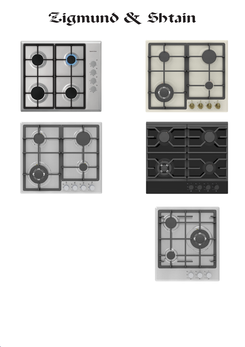
GN 238.451 S,
GN 238.61 S,
GN 238.31.S,
GN 238.61 X
GN 228.61 S,
GN 228.61 B,
GN 228.61 W,
MN 135.61 B
USER MANUAL
РУКОВОДСТВО ПОЛЬЗОВАТЕЛЯ
Page 2

GB
Dear User,
Our objective is to make this product provide you with the best output
which is manufactured in our modern facilities in a careful working
environment, in compliance with total quality concept.
Therefore, we suggest you to read the user manual carefully before
using the product and, keep it permanently at your disposal.
Note: This user manual is prepared for more than one model. Some
of the features specied in the Manual may not be available in your
appliance.
All our appliances are only for domestic use, not for commercial use.
“Conforms with the WEEE Regulations.”
2
Page 3
CONTENTS
GB
Important Warnings
Introduction Of The Appliance
Control Panel
Electrical Connection Scheme
Important Warnings
If Built-In Oven Is Placed Under Cooktop
Installation Of Cookstop
Counter Cutting Sizes And Installation Of Your Cooktop
Correct Place For Installation
Ventilation Of Room
Transformation From Natural Gas To Lpg And
From Lpg To Natural Gas
Gas Breaking Safety Appliance (FFD)
Usage Of Your Cooktop
Pot Diameter 16
Wok Burner 17
Usage Of Hotplate 17
Maintenance And Cleaning
Troubles And Solution Proposals
Setting Gas Cooktops As Per Gas Type 19
Injector, Gas Flow And Power Table 20
Environmentally-Friendly Disposal And
Package Information
4
6
7
7
8
10
10
12
13
13
14
14
15
18
19
21
3
Page 4

GB
IMPORTANT WARNINGS
1. WARNING: Before touching the connection terminals,
all supply circuit should be disconnected.
2. WARNING: Any inadvertent cooking made with fats and
oils can be dangerous and cause re.
3. WARNING: Risk of re; do not store the food materials
on the cooking surface.
4. WARNING: During usage the reachable sections can
be hot. Keep the small children away.
5. WARNING: The appliance and its reachable sections
become hot during usage.
6. The setting conditions of this appliance is indicat-
ed on the label. (Or data tag)
7. This appliance is not connected to a combustion product discharge system.This appliance shall be connected
and installed as per the applicable installation legislation.
Consider the requirements related with ventilation.
8. Using a gas hob will release humidity and combustion products in the room where it resides. Especially
during when the appliance in use, ensure that the kitchen is well ventilated and retain the natural ventilation
holes or install a mechanical ventilation system. (Hood
on top of the oven) Sustained usage of the appliance
may require additional ventilation. For example opening a window or if available, increasing the ventilation
level of a mechanical ventilation system.
9. WARNING: The appliance is intended for cooking only.
It must not be used for other purposes like room heating.
4
Page 5

GB
10. This appliance should be installed as per regula-
tions and in well-ventilated location only. Read the instructions before installing or operating the appliance.”
11. Before placing the appliance check the local
conditions (gas type and gas pressure) and ensure
that the settings of the appliance is appropriate.
12. These instructions are applicable for countries of
which symbols are indicated on the appliance. If the
country symbol is not available on the appliance, in
order to adapt the appliance to the conditions of such
country, the technical instructions should be read.”
13. Do not operate the system for more that 15
seconds. If the burner does not ignite at the end of
15 seconds stop the operation of the system and open
the section door and/or wait for at least 1 minute
before igniting the burner.
14. Do not use steam cleaners to clean the appliance.
15. NEVER try to extinguish a re with water, rst
disconnect the mains supply and then using, for
example a lid or blanket, cover the re.
16. Unless continuous supervision is provided, the
children of age 8 or below should be kept away.
17. Pay attention for not to touch the heating elements.
18. This appliance can be used by children aged
from 8 years and above and persons with reduced
physical, sensory or mental capabilities or lack of
experience and knowledge if they have been given supervision or instruction concerning use of the appliance
in a safe way and understand the hazards involved.
5
Page 6
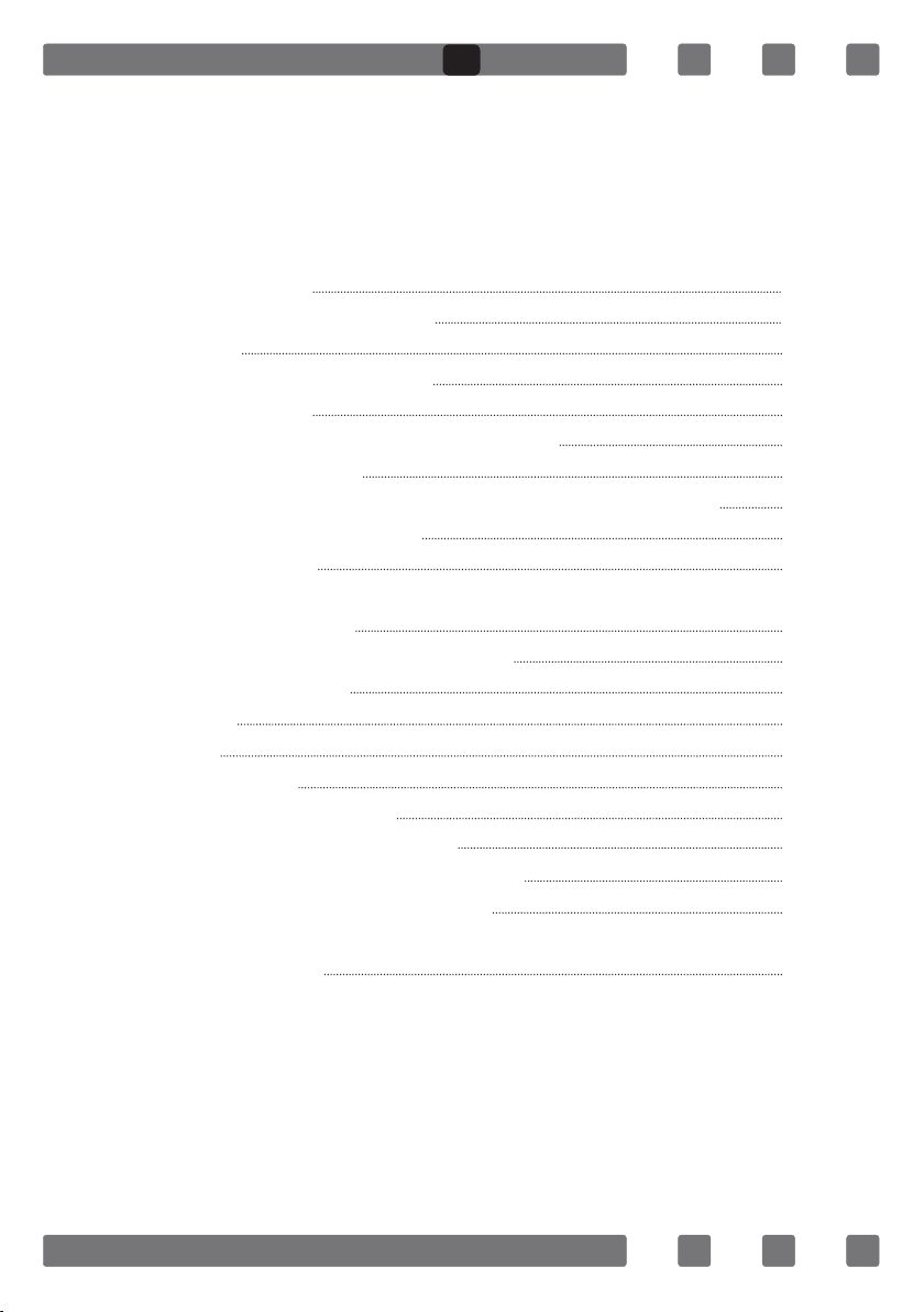
INTRODUCTION OF THE APPLIANCE
1
3
4 5 6 7
GB
2
8
11
1 - Burner positions
2- Glass or Metal Surface
3- Control Buttons
4- Small Burner
5- Medium Burner
6- Large Burner
9 10
12
7 - WOK Burner
8- Hotplate
9- Coffee Adaptor
10-Wok Burner Adaptor
11- Cast Grill
12- Enamel Grill
6
Page 7
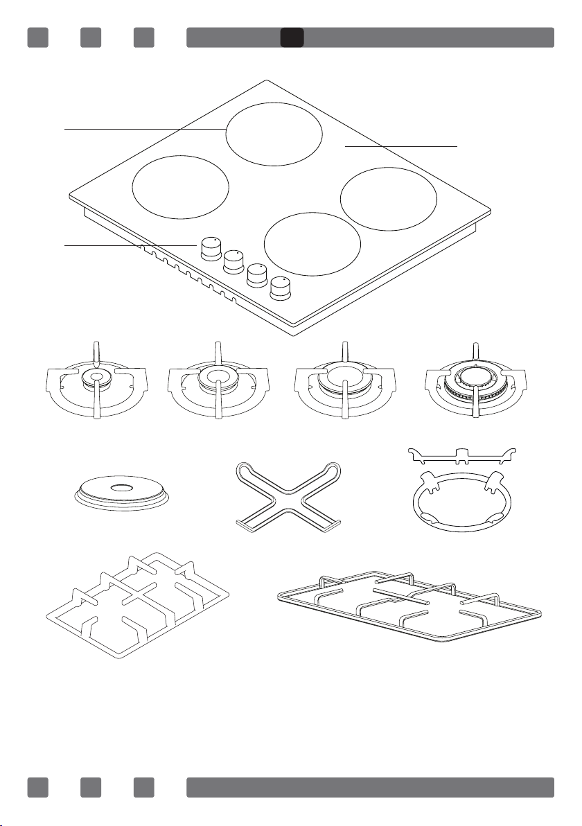
CONTROL PANEL
GB
Cooktop Panel Visual of 70-90 cm and 100 cm
Cooktop Panel Visual of 60 cm
Cooktop Panel Visual of 45 cm
Cooktop Panel Visual of 30 cm
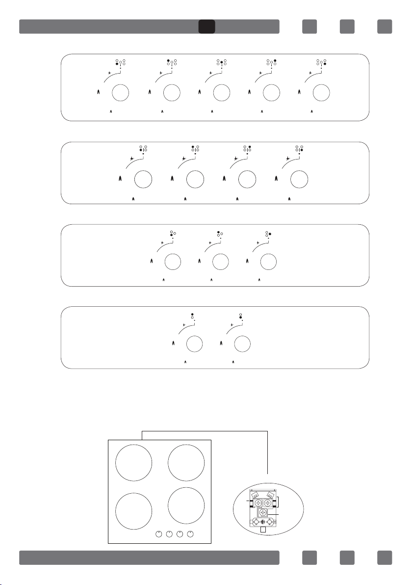
ELECTRICAL CONNECTION SCHEME
Get electrical connection of your appliance done to authorized person in
line with the following scheme.
220-240V~50/60Hz
L1
H05 VV-F 3G 1.5mm²
Neutral
Neutre
Earth
Terre
Erdung
7
Page 8

GB
IMPORTANT WARNINGS
Electrical Connection and Safety
1.Setting conditions of this appliance is indicated in tag or data plate.
2.This appliance is not connected to any discharging apparatus of burn-
ing products. It should be connected and installed according to applicable assembly regulation.
3.Great attention should be paid on ventilation related conditions.
4.Your appliance should be connected to an appropriate fuse according to
electric power. If necessary, it is recommended that connection is made by
authorized service.
5.Your appliance is congured in accordance with electrical supply of
220-240V, 50/60Hz.
6.If main electrical network is different from these values, contact with
your authorized service.
7.Electrical connections of your appliance should only be made to the
fuses having suitably wired grounding (grounded) system. If no convenient fuse is available in the place where your appliance is to be installed,
contact with authorized service immediately. Manufacturing rm is not
responsible denitely for the damages that fuses whose grounding is not
made and connected to the appliance can cause.
8.Plug of the appliance should be close to be accessed easily to the fuse
whose grounding is made without use of extension cord.
9.Do not allow contacting the power cable of your appliance with hot
regions. Similarly, keep away it from sharp edges and corners.
10.If feeder cord is damaged, this cord should be replaced either by
manufacturer or its service agency or same degree qualied personnel in
order to hinder a dangerous situation.
11.Wrong electrical connection may give damage to the appliance. In
this case, your appliance will remain out of guarantee scope. Electrical
connection of your appliance should be done by authorized service.
12.During operation of cooktop, some parts may be hot. When you also
bring switches closed position, it may remain hot for a while. Children
should be kept away every time and not be left without observation. Do
not touch surface of cooktop while warning lights ashes. When you bring
your appliance closed position, hot parts being still dangerous are stated
with warning lights. (Vitroceran models).
8
Page 9
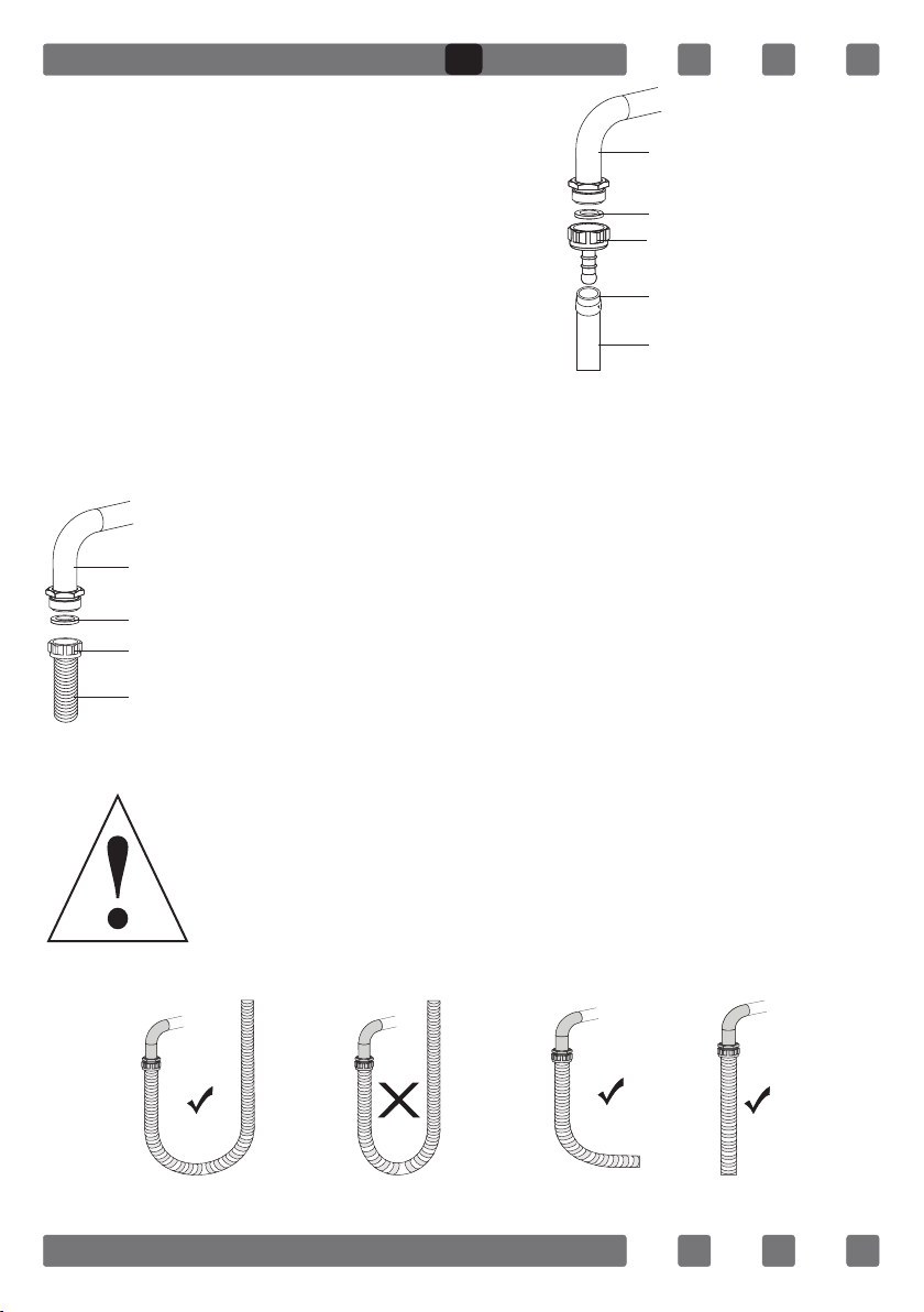
Gas Connection and Safety
GB
1. For LPG (cylinder) connection, afx
metal clamp on the hose coming from
Main Gas Pipe
LPG cylinder. Afx an edge of the hose on
hose inlet connector behind the appliance
by pushing to end through heating the
Gasket
Hose Inlet Connector
hose in boiled water. Afterward, bring the
clamp towards end section of the hose and
Metal Clamp
tighten it with screwdriver. The gasket and
hose inlet connector required for connec-
Lpg Connection Hose
tion is as the picture shown below.
NOTE: The regulator to be afxed on LPG cylinder should have 300
mmSS feature.
2. Natural gas connection should be
Main Gas Pipe
Gasket
Nut
Natural Gas Connection Hose
done by authorized service. For natural
gas connection, place gasket in the nut
at the edge of natural gas connection
hose. To install the hose on main gas
pipe, turn the nut. Complete the connection by making gas leakage control.
Gas hose and electric connection of the appliance should
not pass next to hot areas such as back of the appliance.
Gas hose should be connected by making wide angle turns
against breaking possibility. Movement of appliance whose
gas connection is made may cause gas leakage.
True False True True
9
Page 10
GB
3. Connect your appliance to gas cock from the shortest way and in
a manner to prevent any leakage. For safety, the hose used should be
maximum 125 cm and minimum 40 cm.
4. While making gas leakage control; never use lighter, match, glowing
cigarette or similar inammable matter.
5. Apply soap bubble on connection point. If any leak/leakage exists,
foaming will occur on soaped region.
6. If the cooktop is to be mounted on a cabinet or openable drawer,
a heat protection panel having 15 mm minimum opening should be
mounted under the cooktop.
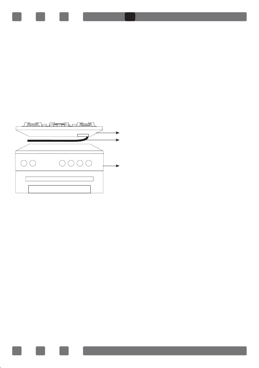
IF BUILT-IN OVEN IS PLACED UNDER COOKTOP;
Cooktop
Hose
Oven
Figure 1
Gas pipe should be afxed in a way not to touch the oven below, sharp
edges and corners, not to be pulled in a manner to be twisted and
strained. Make gas connection from right part of the cooktop, fasten the
hose by use of clamp.
INSTALLATION OF COOKSTOP
1. Detach the burners, burner hoods and grills from the product.
2. Turn the cooktop down and place on smooth ground.
3. In order to prevent entrance of foreign substances and liquids be-
tween cooktop and counter, apply the paste given in package to the sides
of lower guard of counter. For corners, curl paste and increase curls till
lling corner gaps.
4. Turn cooktop again and align with and place on counter.
5. Fasten up your cooktop on counter by using the clamp and screws
supplied.
On the assembly chart given in next page, it is shown how to assemble
your cooktop.
10
Page 11

Roving
GB
Figure 2
6. When product is mounted on a drawer, if it is possible to touch lower
side of product, this section should be separated with a wooden shelf.
min. 30 cm
Figure 3
7. While mounting cooktop on a closet, as shown in the gure above, in
order to separate between closet and cooktop, a shelf should be mounted.
If it is mounted on a built-in oven, there is no need to do that.
8. If your cooktop will be mounted next to right or left wall, the
minimum distance between wall and cooktop should be 50 mm.
11
Page 12
GB
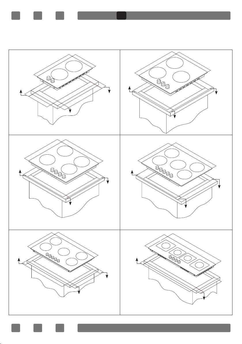
COUNTER CUTTING SIZES AND INSTALLATION OF YOUR COOKTOP
Pay attention to the drawings and dimensions given below while making
cooktop installation and adjusting counter cutting sizes.
min. 60 mm
min. 60 mm
520 mm
270 mm
min. 60 mm
Cooktop Of 30cm
520 mm
560 mm
min. 60 mm
Cooktop Of 60cm
300 mm
490 mm
590 mm
490 mm
min. 60 mm
min. 60 mm
min. 60 mm
min. 110 mm
520 mm
410 mm
min. 60 mm
520 mm
560 mm
Cooktop Of 70cm
440 mm
490 mm
min. 60 mm
Cooktop Of 45cm
690 mm
490 mm
min. 60 mm
min. 60 mm
min. 60 mm
520 mm
810 mm
Cooktop Of 90cm
860 mm
490 mm
min. 60 mm
min. 60 mm
12
min. 60 mm
400 mm
960 mm
Cooktop Of 100cm
990 mm
370 mm
min. 60 mm
Page 13
GB
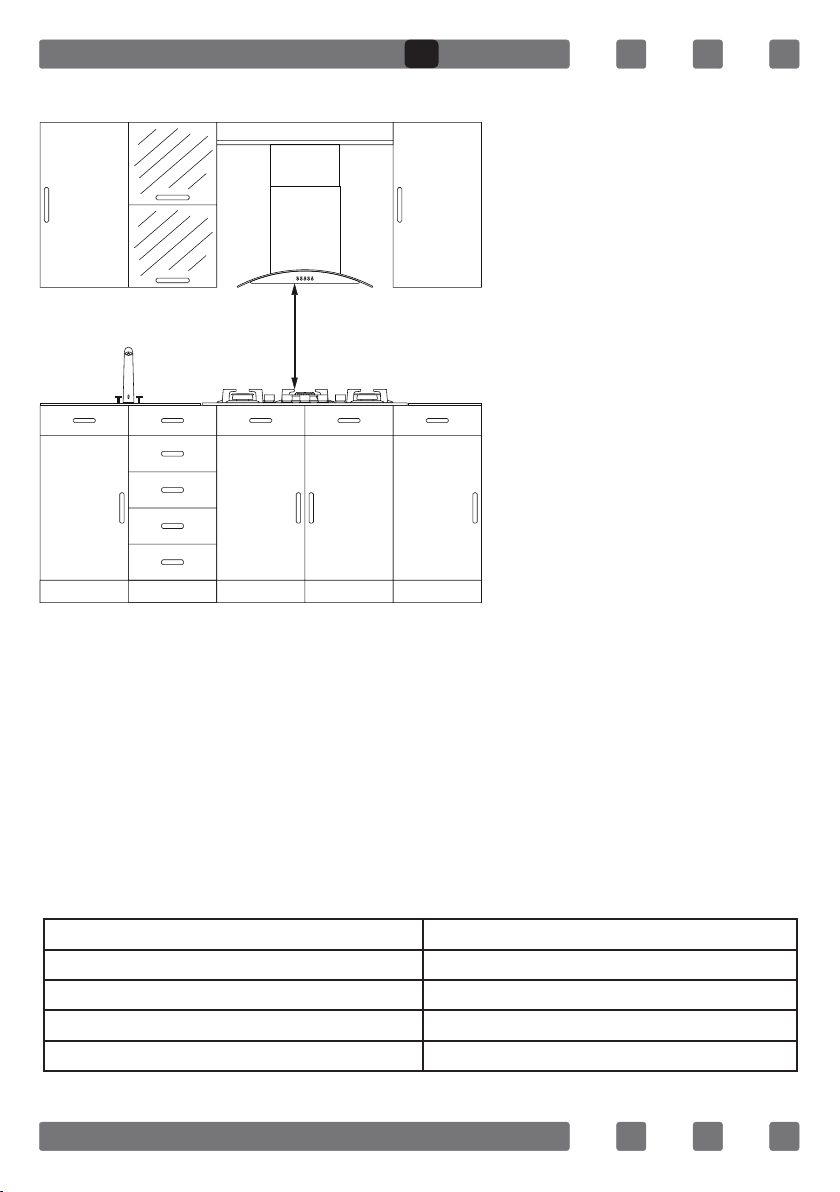
CORRECT PLACE FOR INSTALLATION
Product is designed in
accordance with the kitchen counters supplied from
market. A safe distance
should be left between the
product and kitchen walls
and furniture.
If hood/aspirator will be in-
650 mm min.
stalled over your appliance,
obey to the recommendation of hood/aspirator
manufacturer for assembly
height. (min. 65 cm)
The gap that cooktop is to
be placed on the counter
should be cut in line with
cooktop installation dimensions.
For installation of the product, the rules specied in local standards
related to electricity should be complied.
VENTILATION OF ROOM
The air needed for burning is received from room air and the gases
emitted are given directly in room. For safe operation of your product,
good room ventilation is a precondition. If no window or room to be
utilized for room ventilation is available, additional ventilation should be
installed. However, room has a door opening outside, it is no needed to
vent holes.
Room Size Ventilating Opening
Smaller than 5m³ min. 100 cm²
Between 5 m³- 10m³ min. 50 cm²
Bigger than 10m³ no need
In basement or cellar min. 65 cm²
13
Page 14
GB
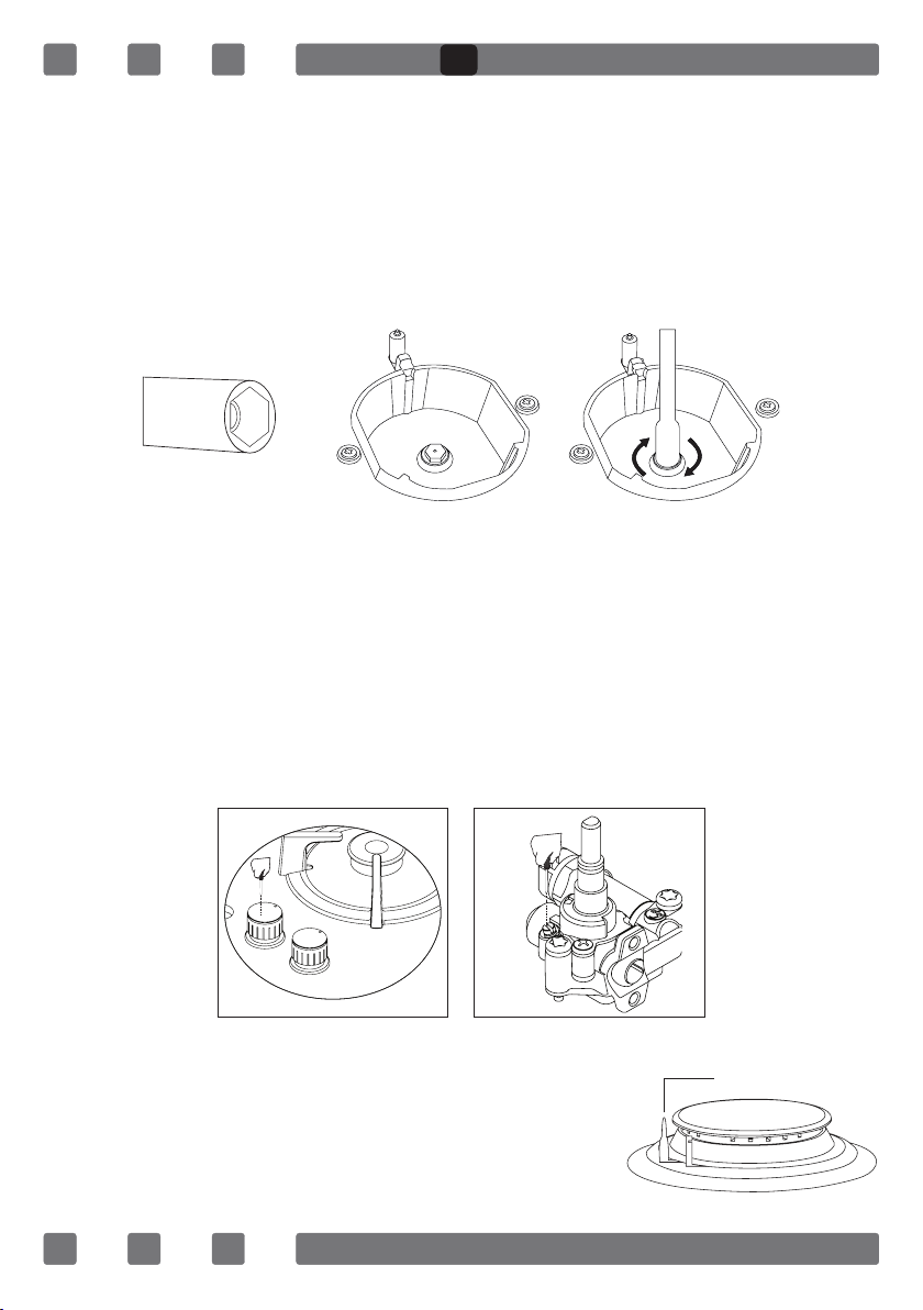
TRANSFORMATION FROM NATURAL GAS TO LPG AND FROM LPG TO NATURAL GAS
1. Turn off gas and electricity of the cooktop. If your cooktop is hot, wait
for cooling down.
2.For injector change, use a screwdriver whose edge is as the Figure 4.
3. As seen in Figure 5, demount burner lid and burner of the cooktop
and ensure visibility of injector.
4. Remove injector by turning as shown in Figure 6 with screwdriver and
replace it with a new one.
Figure 4 Figure 5 Figure 6
5. After that, detach control switches of the cooktop. Make setting by
turning the screw in the middle of gas cocks with a small screwdriver
in the manner shown in the following picture. To adjust ow rate screw,
use a screwdriver having suitable dimension. For LPG, turn the screw
clockwise. For natural gas, turn the screw one time counter clockwise.
At low position, length of normal ame should be 6-7 mm. For the last
control, check out whether ame is open or closed.
Setting of your appliance may differ according to the type of gas cock
used.
Figure 7 Figure 8
GAS BREAKING SAFETY APPLİANCE (FFD)
Against putting out to be taken place as a
result of liquid overow at upper burners, safety
appliance steps in and cut gas immediately.
14
FFD
Figure 9
Page 15

GB
USAGE OF YOUR COOKTOP
Usage of Gas Cooktop
1. Before starting to use your cooktop, be sure burner hoods are at
correct position. Correct placement of burner hoods are shown in the
following gure.
Figure 10 Figure 11
2. Gas cocks have a special locking mechanism. Therefore, to operate
cooktop zone, press button by pushing ahead and while opening or closing the cock, hold down the button.
Closed Fully open Half open
3. For automatic igniting models, igniting is realized via electricity.
Therefore, before operating appliance, be sure that appliance has electric
connection. Igniting for these models is as follows.
Cooktop cock
is at closed
position.
To ignite cook-
top, rstly press
the button
towards ahead.
While hold-
ing down the
button, lighter
steps in and
starts to
ignition.
By turning the
button right while
holding down,
you can provide
ignition at ame
length you want.
4. Pay attention that cooktop grills are placed on cooktop table
completely. In case of failure about this matter can cause pouring of the
materials to be put on that.
5. For the models having gas putting out safety, following realizing
ignition procedure according to the guidelines above, wait for 5-10
seconds by pushing button ahead without keeping your hands off. Safety
15
Page 16

GB
mechanism will step in this duration and ensures operation of the cooktop. With regard to gas putting out appliance, gas cock cuts the gas going
to cooktop zone in case of putting out of cooktop ame due to any reason.
6. While using coffee pot apparatus supplied along with the cooktop, be
sure that foots of apparatus are placed on cooktop grill exactly and remain
on cooktop zone in centred way. Use the apparatus only on small burner.
7. While utilizing gas cooktops, use saucepan, placed on cooktop surface as far as possible. Thanks to that, you can save energy. In the following table, cooking pot diameters recommended to be used as per burners
are given. Characteristic of Wok cooktop zone is to cook quickly.
POT DIAMETER
GLASS HOBS
Domino
Small Burner 12-18cm 12-18cm 12-18cm 12-18cm 12-18cm 12-18cm
Middle Burner --- 18-20cm 18-20cm 18-20cm 18-20cm 18-22cm
Big Burner 18-24cm 22-24cm 22-24cm 22-24cm 22-24cm 22-26cm
45cm.
Hobs
60cm.
Hand
Control
60cm.
Control
Front
70cm.
Control
Front
90cm.
Control
Front
Wok Burner 24-26cm --- 24-26cm 24-26cm 24-26cm 26-30cm
METAL HOBS
Domino
Small Burner 12-18cm 12-18cm 12-18cm 12-18cm 12-18cm 12-18cm
Middle Burner --- 18-20cm 18-20cm 18-20cm 18-20cm 18-22cm
Big Burner 18-22cm 22-24cm 22-26cm 22-24cm 22-24cm 22-26cm
Wok Burner 24-26cm 24-26cm 24-26cm 24-26cm 24-26cm 26-32cm
45cm.
Hobs
60cm.
Hand
Control
60cm.
Control
Front
70cm.
Control
Front
90cm.
Control
Front
False TrueFalseFalse
Cooking pot to be used with products should have minimum 120 mm. diameter.
16
Page 17

GB
WOK BURNER
As it possesses double ring ame system, it gives
homogenous heat distribution at the bottom of
cooking pot at high temperature. It is ideal for
short term and high temperature cooking. When
you want to use regular cooking pot on wok burner,
it is necessary that you remove wok cooking pot
Figure 12
carrier from cooktop.
USAGE OF HOTPLATE
You can operate electric cooktops by turning the button on control panel
you want to use to the level you desire. Cooktop powers as per levels are
given in the following table.
LEVEL 1 LEVEL 2 LEVEL 3 LEVEL 4 LEVEL 5 LEVEL 6
Ø80mm
Ø145mm
Ø180mm
Ø145mm Rapid
Ø180mm Rapid
Ø145mm
Ø180mm
Ø145mm Rapid
Ø180mm Rapid
200W 250W 450W --- --- ---
250W 750W 1000W --- --- ---
500W 750W 1500W --- --- ---
500W 1000W 1500W --- --- ---
850W 1150W 2000W --- --- ---
95W 155W 250W 400W 750W 1000W
115W 175W 250W 600W 850W 1500W
135W 165W 250W 500W 750W 1500W
175W 220W 300W 850W 1150W 2000W
17
Page 18

GB
MAINTENANCE AND CLEANING
Before starting to maintenance or cleaning, rstly unplug the plug
supplying electricity to cooktop and turn off gas valve. If cooktop is hot,
wait for cooling down.
1. For the purpose that your cooktop has long and economic life, regular
cleaning and maintenance should be performed on your cooktop.
2. Do not clean your cooktop with scratching tools such as bristle
brush, wire wool or knife. Do not use abrasive, scratching, acid materials
or detergent.
3. Following mopping parts of your cooktop with soapy cloth, rinse it,
later rinse well with a soft cloth.
4. Clean glass surfaces with special glass cleaning substances. As
scratching of glass surfaces leads to breaking, while cleaning glass
surfaces, do not use abrasive cleaners or sharp metal scrapers.
5. Do not clean your cooktop with steamy cleaners.
6. Clean channels and lids of cooktop zones with soapy water and clean
gas channels with a brush.
7. In the course of cleaning your cooktop, never use ammable materials
such as acid, thinner and gas.
8. Do not wash plastic and aluminium parts of your cooktop in
dishwasher.
9. Clean vinegar, lemon, salt, coke and similar acid and alkaline
containing substances poured on your cooktop immediately.
10. In time, cooktop buttons turns hard or never turn any more, in
such circumstances, it may be necessary that buttons are changed. The
change should only be done by authorized service.
Figure 13 Figure 14
18
Figure 15
Page 19

GB
TROUBLES AND SOLUTION PROPOSALS
You can solve the troubles you can encounter at your product by checking
the following points before calling technical service.
If cooktop does not operate;
• Check if power cable of cooktop is plugged in
• Examine with safe ways if electric exists on network
• Audit fuses.
• Control whether damage is available on power cable.
• Check if main gas valve in your network is open
• Go through existence of breaking or twisting on gas pipe
• Be sure that gasp pipe is connected to cooktop in appropriate way.
• See over if suitable gas valve is used for your cooktop
(Get periodical maintenance done.)
If starter does not operate;
• Be sure that electric power cable of product is plugged in
• Clean the edge and body sections of ignition spark plugs found on
burners with a wet and dirt remover materials thoroughly. Be sure that the
channels present on burners are open and clean.
SETTING GAS COOKTOPS AS PER GAS TYPE
Gas type (LPG or natural gas) that your appliance is manufactured
foris stated in the label found behind the product and that show
technical features. If gas setting of your appliance is not the same as
gas setting of your network, it should be adjusted by making change by
an expert person. In the following table, injector, gas ow and power
values of appliance is given according to gas type.
19
Page 20

GB
INJECTOR, GAS FLOW And POWER TABLE
BURNER
SPECIFICATIONS
Wok
Burner
Rapid
Burner
Semi-Rapid
Burner
Auxiliary
Burner
BURNER
SPECIFICATIONS
Wok
Burner
Rapid
Burner
Semi-Rapid
Burner
Auxiliary
Burner
G20,20 mbar
G25,25 mbar
Gas Natural Gas Natural Gas Natural
Injector 1,40 mm 1,28 mm 1,60 mm
Gas Flow 0,333 m³/h 0,333 m³/h 0,333 m³/h
Power 3,50 kW 3,50 kW 3,50 kW
Injector 1,15 mm 1,10 mm 1,45 mm
Gas Flow 0,276 m³/h 0,276 m³/h 0,276 m³/h
Power 2,90 kW 2,90 kW 2,90 kW
Injector 0,97 mm 0,92 mm 1,10 mm
Gas Flow 0,162 m³/h 0,162 m³/h 0,162 m³/h
Power 1,70 kW 1,70 kW 1,70 kW
Injector 0,72 mm 0,70 mm 0,85 mm
Gas Flow 0,96 m³/h 0,96 m³/h 0,96 m³/h
Power 0,95 kW 0,95 kW 0,95 kW
INJECTOR, GAS FLOW And POWER TABLE
G30,28-30 mbar
G31,37 mbar
LPG LPG LPG
Injector 0,96 mm 0,76 mm 0,96 mm
Gas Flow 254 g/h 254 g/h 254 g/h
Power 3,50 kW 3,50 kW 3,50 kW
Injector 0,85 mm 0,75 mm 0,85 mm
Gas Flow 211 g/h 211 g/h 211 g/h
Power 2,90 kW 2,90 kW 2,90 kW
Injector 0,65 mm 0,60 mm 0,65 mm
Gas Flow 124 g/h 124 g/h 124 g/h
Power 1,70 kW 1,70 kW 1,70 kW
Injector 0,50 mm 0,43 mm 0,50 mm
Gas Flow 69 g/h 69 g/h 69 g/h
Power 0,95 kW 0,95 kW 0,95 kW
G20,25 mbar G20,13 mbar
G30,50 mbar G30,37 mbar
20
Page 21

GB
ENVIRONMENTALLY-FRIENDLY DISPOSAL
1. Dispose of packaging in an environmentally-friendly
manner.
2. This appliance is labelled in accordance with European Directive 2012/19/EU concerning used electrical
and electronic appliances (waste electrical and electronic equipment - WEEE). The guideline determines
the framework for the return and recycling of used appliances as applicable throughout to the EU.
PACKAGE INFORMATION
Packaging materials of the product are manufactured from recyclable
materials in accordance with our National Environment Regulations.
Do not dispose of the packaging materials together with the domestic
or other wastes. Take them to the packaging material collection points
designated by the local authorities.
21
Page 22

RU
Уважаемый пользователь,
Наша продукция произведена с использованием современных
технологических возможностей и квалифицированного
производственного и технического персонала, для достижения высокого
качества.
Мы рекомендуем Вам внимательно ознакомиться с руководством по
эксплуатации и сохранить его для дальнейшего использования.
Примечание:
Это руководство подготовлено не для одной модели плит. Некоторые
функциональные возможности могут быть не реализованы в Вашей
модели.
Соответствует Правилам WEEE
22
Page 23

СОДЕРЖАНИЕ
RU
Важные Предупреждения
Описание Прибора
Пульты Улраbлehия 28
Схема Электрического Подключения 28
Важные Предупреждения 29
Если Под Плитой Установлена Встроенная Духовка
Монтаж Плиты На Место
Размеры Места Под Плиту И Установка Плиты 33
Правильное Место Для Монтажа 34
Вентиляция Помещения 34
Преобразование Из Природного Газа В Lpg И Из Lpg В
Природный Газ 35
Защитный Механизм Отключения Газа (FFD) 35
Эксплуатация Плиты 36
Диаметр Горшок 37
Горелка Wok
Использование Портативных Нагревателей
Техническое Обслуживание И Чистка 38
Проблемы И Рекомендации По Их Устранению 40
Инжектор, Потребление И Мощность Таблица 41
Утилизация С Учетом Экологических Требований И
Информация Об Упаковке 42
24
27
31
31
38
38
23
Page 24

RU
ВАЖНЫЕ ПРЕДУПРЕЖДЕНИЯ
1. ВНИМАНИЕ! Прежде чем касаться клемм,
следует обесточить все цепи питания.
2. ВНИМАНИЕ! Несоблюдение осторожности
при готовке с использованием жиров и масел
представляет опасность и может привести к
возгоранию.
3. ВНИМАНИЕ! Опасность возгорания: не
кладите продукты на рабочую поверхность.
4. ВНИМАНИЕ! Досягаемые части могут
нагреваться при использовании. Не
подпускайте к устройству маленьких детей.
5. ВНИМАНИЕ! Устройство и его досягаемые
части нагреваются при использовании.
6. Условия установки данного устройства
указаны на заводской табличке. (Или на бирке
с информацией.)
7. Данное устройство не подсоединено к системе
сброса продуктов сгорания. Данное устройство
следует подключить и установить в соответствии
с применяемыми нормативными актами по
установке. Учтите требования, связанные с
вентиляцией.
8. Использование газовой конфорки приведет
к выбросу влаги и продуктов горения в комнату,
где размещено устройство. Убедитесь, что кухня
24
Page 25

RU
хорошо вентилируется, особенно во время
использования устройства, и не закрывайте
естественные вентиляционные отверстия либо
установите механическую систему вентиляции.
Постоянное использование данного устройства
может потребовать дополнительной вентиляции.
Например, открытия окна или перевода
механической системы вентиляции на более
высокий уровень работы.
9. ВНИМАНИЕ! Данное устройство
предназначено только для готовки. Его нельзя
использовать для других целей, таких как
обогрев комнаты.
10. Данное устройство следует устанавливать
в соответствии с нормативами и только в
хорошо проветриваемых помещениях. Прочтите
инструкции перед установкой или использованием
устройства».
11. Перед установкой устройства проверьте
местные условия (тип и давление газа)
и убедитесь, что устройство настроено
соответствующим образом.
12. Эти инструкции относятся к странам,
символы которых указаны на устройстве. Если
символ вашей страны отсутствует на устройстве,
прочтите технические инструкции, чтобы
приспособить устройство к ее условиям.
25
Page 26

RU
13. «Не используйте эту систему розжига
горелки более чем 15 секунд. Если горелка не
загорелась через 15 секунд, отпустите ручку
и откройте дверь минимум одну минуту перед
зажиганием горелки.
14. Не используйте пароочистители для очистки
устройства.
15. НИ В КОЕМ СЛУЧАЕ не пытайтесь гасить
возгорание водой: сначала отключите устройство
от сети, а затем накройте огонь, используя,
например, крышку или одеяло.
16. Не подпускайте к устройству детей до 8 лет,
если нет возможности постоянно наблюдать за
ними.
17. Постарайтесь не касаться нагревательных
элементов.
18. Дети от 8 лет и старше, а также лица с
ограниченными физическими, сенсорными
или умственными способностями или не
обладающие достаточным опытом и знаниями
могут использовать данное устройство под
наблюдением или если им были предоставлены
инструкции по его безопасному использованию,
позволяющие понять связанные с устройством
опасности.
26
Page 27

ОПИСАНИЕ ПРИБОРА
1
3
4 5 6 7
RU
2
8
1 - Положения горелки
2- Стеклянная или
металлическая
поверхность
3- Контрольные кнопки
4- Маленькая горелка
11
9 10
5- Средняя горелка
6- Большая горелка
7 - Горелка WOK
8- Плитка
9- Адаптер для
приготовления кофе
27
12
10- Адаптер для
конфорки Wok
11- Чугунная решетка
12- Эмалированная
решетка
Page 28

ПУЛЬТЫ УЛРАBЛEHИЯ
Изображение панели плиты 70-90 и 100 см
Изображение панели плиты 60 см
Изображение панели плиты 45 см
RU
Изображение панели плиты 30 см
СХЕМА ЭЛЕКТРИЧЕСКОГО ПОДКЛЮЧЕНИЯ
Обеспечьте подключение электрической системы плиты
авторизованным лицом в соответствии со схемой.
220-240B~ 50/60 Гц
L1
H05 VV-F 3G 1,5 мм²
28
Page 29

RU
ВАЖНЫЕ ПРЕДУПРЕЖДЕНИЯ
Электрическое соединение и Безопасность
1. Условия настройки этого устройства указаны на этикетке или
табличке с данными.
2. Настоящее устройство не соединено с оборудованием для
отвода продуктов горения. Это устройство должно быть подключено в
соответствии с инструкциями по монтажу.
3. Необходимо тщательно следить за выполнением требований по
вентиляции.
4. Изделие необходимо подключить к предохранителю,
соответствующей электрической мощности. Рекомендуем
воспользоваться услугами авторизованных сервисов для подключения
данного устройства.
5. Ваше устройство настроено на питание от сети 220-240 V, 50/60Гц.
6. Если параметры электрической сети отличаются от приведенных
выше - обратитесь в авторизованный сервисный центр.
7. Питание устройства должно поступать только от розеток,
обладающих соответствующей системой заземления. Если в месте
расположения устройства не имеется розеток, соответствующих системе
заземления, немедленно обратитесь в авторизованный сервисный
центр. Фирма-изготовитель ни в коем случае не несет ответственность
за повреждения, возникающие вследствие использования розеток без
заземления.
8. Штепсельная вилка устройства должна находиться на расстоянии,
позволяющем легко включить ее в заземленную розетку.
9. Не допускайте контакта электрического шнура устройства с горячими
частями.Также держите его вдали от острых краев и углов.
10. В случае повреждения силового шнура, он должен быть заменен
изготовителем или авторизованным сервисным центром.
11. Неправильное электрическое подключение может нанести вред
Вашему устройству. В таком случае устройство не будет обслуживаться
в рамках гарантии. Электрическое подключение устройства должно
выполняться квалифицированным персоналом авторизованного
сервисного центра.
12. Во время эксплуатации плиты некоторые части будут
нагреваться. Они могут оставаться горячими некоторое время после
выключения. Следует всегда держать детей вдали от устройства и
под присмотром взрослых. Не дотрагивайтесь до поверхности плиты,
когда горят предупредительные лампочки. При выключении плиты
предупредительные лампочки будут продолжать указывать на горячие
части, представляющие опасность (модели Vitroceram).
29
Page 30

RU
Газовое подключение и Безопасность
1. Для подключения баллона со сжиженным
газом наденьте металлический хомут на
шланг, идущий от баллона. Наденьте один
конец шланга на входной фитинг изделия,
нагрев его в кипящей воде. Затем установите
хомут на конце шланга и затяните с помощью
отвертки. Уплотнитель идущий в комплекте,
и входной фитинг для шланга необходимые
для соединения, приведены на рисунке.
ПРИМЕЧАНИЕ: Регулятор, надеваемый на баллон LPG , должен быть
300 mmSS.
2. Подключение к природному
газу должно выполняться
ГЛАВНАЯ ГАЗОВАЯ
ТРУБА
УПЛОТНИТЕЛЬ
ГАЙКА
квалифицированным специалистом.
Для подключения природного газа
установите уплотнитель внутри гайки на
конце крепежного шланга. Прикрутите
гайку к газовой трубе. Проведите
КРЕПЕЖНЫЙ ШЛАНГ ДЛЯ
ПРИРОДНОГО ГАЗА
проверку на утечку и завершите
подключение. Газовый шланг изделия
и электрический кабель не должны проходить рядом с горячими
поверхностями, такими как тыльная часть изделия. Газовый шланг можно
сгибать только под большим углом, чтобы избежать его повреждения
в результате перегибания. Перемещение изделия с подключенным
газовым соединением может привести к утечке газа.
ГЛАВНАЯ ГАЗОВАЯ
ТРУБА
УПЛОТНИТЕЛЬ
ВХОДНОЙ ФИТИНГ
ШЛАНГА
МЕТАЛЛИЧЕСКИЙ
ЗАЖИМ
КРЕПЕЖНЫЙ ШЛАНГ
LPG
пpaвoильно пpaвoильно
Heпpaвильно
пpaвoильно
3. Подключите Вашу плиту к газовому крану кратчайшим путем и
подсоедините его, убедившись в отсутствии утечки. Для соблюдения мер
безопасности используемый шланг должен быть длинной минимум 40
см, максимум 125 см.
30
Page 31

RU
4. Во время проверки на утечку газа нельзя использовать зажигалку,
спички, горящие сигареты или подобные источники огня.
5. Нанесите на точку подключения мыльную пену. При наличии утечки
на области с нанесенной мыльной пеной будут образовываться пузыри.
6. Если плита будет устанавливаться на шкафу или открывающемся
ящике, под плитой необходимо установить панель для защиты от тепла с
зазором минимум 30 мм.
ЕСЛИ ПОД ПЛИТОЙ УСТАНОВЛЕНА ВСТРОЕННАЯ ДУХОВКА,
ПЛИТА
ШЛАНГ
ДУХОВКА
Рис. 1
Газовый шланг не должен касаться духовки, острых краев и углов, его не
следует растягивать и сгибать. Подключите шланг с правой стороны плиты
и, надев зажим, зафиксируйте его.
МОНТАЖ ПЛИТЫ НА МЕСТО
1. Демонтируйте с изделия конфорки, шапки конфорок и решетки.
2. Для предотвращения попадания инородных тел и жидкостей между
плитой и столешницей приклейте монтажную ленту, идущую в комплекте,
по краям нижней части плиты.
3. Зафиксируйте плиту на столешнице, используя зажим и болты. На
монтажной схеме, приведенной на следующей странице, показано, как
смонтировать плиту.
4. В случае монтажа изделия на выдвижном ящике, если его нижняя
часть остается доступной, ее следует отделить деревянной полкой.
31
Page 32

Moнтaжнaя лeнтa
RU
Рис. 2
минимyм 30 мм.
Рис. 3
7. Если изделие устанавливается над полкой кухонного шкафа, то
необходимо установить полку как показано на рисунке выше для того
чтобы оградить низ плиты от шкафа. Если плита монтируется над
встроенной духовкой, то в этом нет необходимости.
8. Если Ваше изделие монтируется рядом с левой или правой стеной,
минимальное расстояние между стеной и плитой должно быть 50мм.
32
Page 33

RU
РАЗМЕРЫ МЕСТА ПОД ПЛИТУ И УСТАНОВКА ПЛИТЫ
При монтаже плиты и подготовке места для ее монтажа в столешнице
следуйте предоставленным размерам
min. 60 mm
min. 60 mm
520 mm
270 mm
520 mm
560 mm
Плита 60 см
min. 60 mm
Плита 30 см
min. 60 mm
300 mm
490 mm
590 mm
490 mm
min. 60 mm
min. 60 mm
min. 60 mm
min. 110 mm
520 mm
410 mm
520 mm
560 mm
440 mm
490 mm
min. 60 mm
690 mm
min. 60 mm
Плита 70 см
min. 60 mm
Плита 45 см
490 mm
min. 60 mm
min. 60 mm
520 mm
810 mm
Плита 90 см
860 mm
490 mm
min. 60 mm
min. 60 mm
33
min. 60 mm
400 mm
960 mm
Плита 100 см
990 mm
370 mm
min. 60 mm
Page 34

RU
ПРАВИЛЬНОЕ МЕСТО ДЛЯ МОНТАЖА
Дизайн изделия разработан
в соответствии с
доступными на рынке
столешницами. Между
стенами кухни и мебелью
следует оставить
безопасное расстояние.
650 mm
минимальный
монтажным размерам плиты. Во время монтажа изделия следует
соблюдать правила, установленные местными стандартами в части
электрических работ.
Если над изделием будет
устанавливаться вытяжка,
соблюдайте требования
изготовителя вытяжки
относительно высоты
монтажа. (Минимум 65 см).
Вырез, в котором будет
установлена плита на
столешнице, должен
соответствовать
ВЕНТИЛЯЦИЯ ПОМЕЩЕНИЯ
Для горения газа используется воздух, находящийся в помещении,
продукты горения газа также выделяются в помещение. Для надежной
работы Вашего изделия обязательным условием является хорошая
вентиляция помещения. Если в помещении отсутствует какоелибо вентиляционное окно или дверь, необходимо установить
дополнительную вентиляцию. Однако при наличии открывающейся
непосредственно из комнаты двери, отпадает необходимость в
вентиляционных отверстиях.
Величина Помещения Вентиляционное Отверстие
меньше 5м³ мин. 100см²
от 5м³ до 10м³ мин. 50см²
больше 10м³ не требуется
в подвале или киллерах мин. 65cм²
34
Page 35

RU
ПЕРЕХОД С ПРИРОДНОГО ГАЗА НА СЖИЖЕННЫЙ И СО
СЖИЖЕННОГО ГАЗА НА ПРИРОДНЫЙ ГАЗ
1. Перекройте подачу газа и отключите электричество от плиты. Если
плита горячая, подождите, пока она остынет.
2. Для замены жиклера используйте ключ с торцевой головкой на 7мм
как на рисунке.
3. Снимите крышку горелки и горелку как указано на рисунке 5.
4. Снимите жиклер с помощью ключа, как указано на Рисунке 6 и
замените его на новый
Рис. 4 Рис. 5 Рис. 6
5. Затем снимите с плиты ручки управления. Отрегулируйте
минимальную подачу газа, провернув болты посередине газовых кранов
отверткой, как показано на рисунке. Для регулировки крана пользуйтесь
отверткой соответствующего размера. Для сжиженного газа поверните
болт по часовой стрелке. Для природного газа поверните болт один раз
против часовой стрелки. В минимальном положении регулятора длина
нормального пламени должна быть 6-7 мм. Во время последнего контроля
проверьте, горит пламя или нет. Настройка устройства может меняться в
зависимости от типа используемого газового крана.
FFD
Рис. 9
Рис. 7
Рис. 8
ЗАЩИТНЫЙ МЕХАНИЗМ ОТКЛЮЧЕНИЯ ГАЗА
(FFD)
Для защиты от возможного затухания в
результате переливания жидкости, используется
защитный механизм отключающий подачу газа.
35
Page 36

RU
ЭКСПЛУАТАЦИЯ ПЛИТЫ
Эксплуатация газовой плиты
1. Перед началом эксплуатации плиты убедитесь в том, что
крышки конфорок находится в правильном положении. Правильное
расположение крышек конфорок приведено на рисунке ниже.
Рис. 10 Рис. 11
Закрыт Полностью открыт Oткрыт напoлoвинy
2. Газовые краны обладают специальным клапаном-блокиратором.
Поэтому для включения конфорки нажмите на ручку и удерживайте ее в
нажатом положении во время открытия или закрытия крана.
3. В моделях с автоматическим запалом запал производится
посредством электричества. Поэтому перед началом эксплуатации
изделия убедитесь в том, что оно подключено к электрической сети. В
этих моделях запал осуществляется следующим образом.
Кран плиты
находится
в закрытом
положении.
Для того,
чтобы зажечь
плиту, вначале
нажмите на
pyчкy.
Когда pyчкa
находится
в нажатом
положении,
зажигалка
включается
и происходит
запал.
Удерживая
pyчкy в нажатом
состоянии и
поворачивая
влево, можно
oтpeгyлиpoвaть
cилy пламени.
4. Следите за тем, чтобы решетки были плотно установлены на плите.
Неустановленная на место решетка может вызвать опрокидывание
находящейся на ней посуды.
36
Page 37

RU
5. В моделях, обладающих предохранительной системой от затухания
газа, после тушения пламени в соответствии с инструкцией выше,
не отпуская ручку, удерживайте её в нажатом положении в течение
5-10 секунд. Защитный механизм сработает в течение этого времени
и конфорка загорится. Для защиты от утечки газа в случае затухания
пламени плиты по какой-либо причине, газовый кран автоматически
отключает газ, поступающий к конфорке плиты.
6. Во время использования приспособления для кофеварки,
предоставляемого вместе с плитой, убедитесь в том, что оно плотно
установлено на решетке плиты и стоит в центре конфорки. Используйте
приспособление только с маленькой конфоркой.
7. При эксплуатации газовой плиты, пользуйтесь по возможности
кастрюлями с длинными ручками, плотно устанавливаемыми на
поверхности плиты. Это обеспечит более эффективный расход энергии.
На таблице ниже приведены диаметры кастрюль, рекомендуемых для
использования с соответствующими конфорками.
ДИАМЕТР ГОРШОК
СТЕКЛЯННЫЕ ВАРОЧНЫЕ ПАНЕЛИ
Домино
Maлaя
Горелка
Cpeдняя Горелка --- 18-20cм 18-20cм 18-20cм 18-20cм 18-22cм
12-18cм 12-18cм 12-18cм 12-18cм 12-18cм 12-18cм
45cm.
Плита
60cm.
Pучное
Yправление
60cm.
Контроль
Передние
70cm.
Контроль
Передние
90cm.
Контроль
Передние
Большaя Горелка 18-24cм 22-24cм 22-24cм 22-24cм 22-24cм 22-26cм
WOK Горелка 24-26cм --- 24-26cм 24-26cм 24-26cм 26-30cм
МЕТАЛЛИЧЕСКИЕ ПЕЧИ
Домино
Maлaя
Горелка
Cpeдняя Горелка --- 18-20cм 18-20cм 18-20cм 18-20cм 18-22cм
Большaя Горелка 18-22cм 22-24cм 22-26cм 22-24cм 22-24cм 22-26cм
WOK Горелка 24-26cм 24-26cм 24-26cм 24-26cм 24-26cм 26-32cм
12-18cм 12-18cм 12-18cм 12-18cм 12-18cм 12-18cм
45cm.
Плита
60cm.
Pучное
Yправление
60cm.
Контроль
Передние
70cm.
Контроль
Передние
90cm.
Контроль
Передние
37
Page 38

RU
ГОРЕЛКА WOK
Конфорка WOK обеспечивает быстрое
приготовление пищи. Она обладает системой
пламени с двойными кольцами, что обеспечивает
равномерное распределение тепла по дну
кастрюли. Является идеальной для быстрого
приготовления пищи при высокой температуре. При
Рис. 12
ИСПОЛЬЗОВАНИЕ ЭЛЕКТРИЧЕСКИХ ПЛИТ
Электрические плиты можно включить, повернув ручку на панели
управления до требуемого уровня. Мощность плиты в зависимости от
уровня приведена в таблице ниже.
Ø80мм
Ø145мм
Ø180мм
Ø145мм Быстрая
Ø180мм Быстрая
Ø145мм
Ø180мм
Ø145мм Быстрая
Ø180мм Быстрая
желании использовать на конфорке WOK обычную
кастрюлю, необходимо снять с плиты подставку для
кастрюли WOK.
УРОВЕНЬ 1УРОВЕНЬ 2УРОВЕНЬ 3УРОВЕНЬ 4УРОВЕНЬ 5УРОВЕНЬ
6
200Вт 250Вт 450Вт ---- ---- ---250Вт 750Вт 1000Вт ---- ---- ---500Вт 750Вт 1500Вт ---- ---- ---500Вт 1000Вт 1500Вт ---- ---- ---850Вт 1150Вт 2000Вт ---- ---- ----
95Вт 155Вт 250Вт 400Вт 750Вт 1000Вт
115Вт 175Вт 250Вт 600Вт 850Вт 1500Вт
135Вт 165Вт 250Вт 500Вт 750Вт 1500Вт
175Вт 220Вт 300Вт 850Вт 1150Вт 2000Вт
ТЕХНИЧЕСКОЕ ОБСЛУЖИВАНИЕ И ЧИСТКА
Перед тем, как начать техническое обслуживание или чистку, вначале
вытяните из розетки штепсельную вилку, обеспечивающую поступление
электричества к плите, и закройте газовый кран. Если плита горячая –
подождите, пока она остынет.
1. Для того, чтобы обеспечить долговечность плиты и её
экономичность, необходимо регулярно проводить её очистку и
техническое обслуживание.
2. Для очистки плиты не пользуйтесь такими твердыми
приспособлениями, как жесткая щетка, проволочная губка или нож. Не
используйте абразивные, царапающие предметы, кислоты или моющие
средства.
38
Page 39

RU
3. Протрите части плиты куском ткани, смоченным в мыльной воде, а
затем тщательно протрите мягкой тканью.
4. Очищайте стеклянные поверхности специальными средствами
для чистки стекол. Царапины на стеклянных поверхностях вызывают
трещины, поэтому для их очистки не пользуйтесь абразивными
чистящими веществами или острыми металлическими скребками.
5. Не очищайте плиту паровыми очистителями.
6. Промойте каналы и крышки конфорок мыльной водой и очистите
газовые каналы с помощью щетки.
7. Для чистки плиты никогда не пользуйтесь кислотой, растворителем,
керосином или другими горючими веществами.
8. Не мойте пластиковые и алюминиевые части плиты в посудомоечной
машине.
9. Как можно быстрее очищайте плиту от уксуса на ее поверхности,
лимонного сока, соли, колы и других кислотных и щелочных веществ.
10. Со временем ручки плиты могут с трудом поворачиваться или не
поворачиваться вообще, в таком случае их следует заменить. Замена
должна осуществляться только авторизованным сервисом.
Рис. 13 Рис. 14
39
Рис. 15
Page 40

RU
ПРОБЛЕМЫ И РЕКОМЕНДАЦИИ ПО ИХ УСТРАНЕНИЮ
Перед тем как обращаться в сервисную службу, попробуйте
воспользоваться следующими рекомендациями для устранения
проблем.
Если плита не работает:
• Проверьте, вставлена ли штепсельная вилка электрического шнура в
розетку.
• Проверьте безопасными способами наличие электричества в сети.
• Проверьте предохранители.
• Проверьте наличие повреждений электрического шнура.
• Проверьте, открыт ли главный газовый кран.
• Проверьте газовый шланг на наличие перекручивания или разломов.
• Убедитесь в правильности подключения газового шланга к плите.
• Проверьте, использован ли для плиты подходящий газовый кран.
Если зажигалка не работает:
• Проверьте, вставлена ли штепсельная вилка электрического шнура в
розетку.
• Тщательно очистите концы, и корпусы свечей поджига конфорок
веществом для удаления грязи. Убедитесь в том, что каналы конфорок
являются открытыми и чистыми.
НАСТРОЙКА ГАЗОВЫХ ПЛИТ В ЗАВИСИМОСТИ ОТ ТИПА ГАЗА
Вид газа, для которого изготовлено ваше устройство (Сжиженный
или Природный газ), указан на табличке с описанием технических
характеристик. Если настройка типа газа устройства не соответствует
типу газа сети, необходимо произвести настройку с помощью
специалиста. В нижеуказанной таблице приведены диаметры жиклеров,
давление газа, потребление газа и мощность в зависимости от типа газа.
При настройке плиты специалистом необходимо принимать во внимание
эту таблицу.
40
Page 41

ИНЖЕКТОР, ПОТРЕБЛЕНИЕ И МОЩНОСТЬ ТАБЛИЦА
СООТВЕТСТВИЕ
ДИАМЕТРОВ
ЖИКЛEРОВ
ТИПУ ГАЗА
Wok
Горелка
Большая
Горелка
Средняя
Горелка
Малая
Горелка
ИНЖЕКТОР, ПОТРЕБЛЕНИЕ И МОЩНОСТЬ ТАБЛИЦА
СООТВЕТСТВИЕ
ДИАМЕТРОВ
ЖИКЛEРОВ
ТИПУ ГАЗА
Wok
Горелка
Большая
Горелка
Средняя
Горелка
Малая
Горелка
RU
G20,20 mbar
G25,25 mbar
Природный Газ Природный Газ Природный Газ
Жиклep 1,40 мм 1,28 мм 1,60 мм
Потребление 0,333 м³/ч 0,333 м³/ч 0,333 м³/ч
Мощность 3,50 кВт 3,50 кВт 3,50 кВт
Жиклep 1,15 мм 1,10 мм 1,45 мм
Потребление 0,276 м³/ч 0,276 м³/ч 0,276 м³/ч
Мощность 2,90 кВт 2,90 кВт 2,90 кВт
Жиклep 0,97 мм 0,92 мм 1,10 мм
Потребление 0,162 м³/ч 0,162 м³/ч 0,162 м³/ч
Мощность 1,70 кВт 1,70 кВт 1,70 кВт
Жиклep 0,72 мм 0,70 мм 0,85 мм
Потребление 0,96 м³/ч 0,96 м³/ч 0,96 м³/ч
Мощность 0,95 кВт 0,95 кВт 0,95 кВт
G30,28-30 mbar
G31,37 mbar
LPG LPG LPG
Жиклep
Потребление
Мощность
Жиклep
Потребление
Мощность
Жиклep
Потребление
Мощность
Жиклep
Потребление
Мощность
0,96
254
3,50
0,85
211
2,90
0,65
124
1,70
0,50
69
0,95
мм
м³/ч
кВт
мм
м³/ч
кВт
мм
м³/ч
кВт
мм
м³/ч
кВт
G20,25 mbar G20,13 mbar
G30,50 mbar G30,37 mbar
0,76
254
3,50
0,75
211
2,90
0,60
124
1,70
0,43
69
0,95
мм
м³/ч
кВт
мм
м³/ч
кВт
мм
м³/ч
кВт
мм
м³/ч
кВт
0,96
254
3,50
0,85
211
2,90
0,65
124
1,70
0,50
69
0,95
мм
м³/ч
кВт
мм
м³/ч
кВт
мм
м³/ч
кВт
мм
м³/ч
кВт
41
Page 42

RU
УТИЛИЗАЦИЯ С УЧЕТОМ ЭКОЛОГИЧЕСКИХ ТРЕБОВАНИЙ
Утилизируйте упаковку с учетом требований по охране окружающей
среды. Данное устройство маркировано в соответствии с требованиями
Директивы ЕС 2012/19/EU по утилизации использованных электрических
и электронных устройств (утилизация электрического и электронного
оборудования WEEE). Там указаны требования по возврату и
переработке использованных устройств, применимые во всех странах
Европейского Союза.
ИНФОРМАЦИЯ ОБ УПАКОВКЕ
Упаковочные материалы устройства изготовлены из материалов,
подлежащих вторичной переработке, в соответствии с местными
нормативами и правилами касательно защиты окружающей среды.
Не утилизируйте упаковочные материалы вместе с бытовыми или
другими отходами. Сдайте их на пункт сбора упаковочных материалов,
определенный местными властями.
42
Page 43

Основной импортер товара Zigmund & Shtain в России:
ООО «Элеком» РФ, г. Москва, Очаковское шоссе дом 36,
помещение 8.
Тел.: +7 968 336 38 26
Email: elekom_ooo@mail.ru
Срок службы – 25 лет со дня покупки, при использовании в
строгом соответствии с настоящей инструкцией по эксплуатации и
применимыми техническими стандартами.
Веб-сайт; www.zigmundshtain.ru
Информацию об авторизованных сервисных центрах и условиях
гарантийного обслуживания Вы можете узнать на веб-сайте и в
гарантийном талоне.
Если в Вашем городе отсутствует авторизованный сервисный
центр, Вам следует обратиться в магазин, где Вы приобрели наш
товар, и он организует ремонт, или замену.
Страна происхождения – Турция
Настоящая информация является частью сопроводительной
технической документации, прилагаемой к товару. Изготовитель
постоянно работает над совершенствованием конструкции и
технических характеристик выпускаемой продукции, в том числе
над улучшением энергетической эффективности.
Изготовитель оставляет за собой право на внесение изменений
в конструкцию, оснащение и технические характеристики прибора
без предварительного уведомления. Ассортимент выпускаемой
продукции постоянно обновляется и расширяется, информация в
настоящем издании может периодически меняться.
По истечению срока службы техника не обслуживается, запчасти
не поставляются, авторизованный сервисный центр вправе
отказать в ремонте. Дальнейшая эксплуатация может повлечь
невозможность нормального использования товара.
Товар необходимо передать специализированным компаниям,
которые занимаются утилизацией данного вида продукции.
43
Page 44

Утилизация упаковки.
Упаковка изготовлена из экологически чистых материалов,
которые можно без ущерба для окружающей среды подвергать
переработке, складировать на специальных полигонах для
хран¬¬ения отходов и утилизировать. Упаковочные материалы
имеют соответствующую маркировку.
Отслужившее изделие нужно сделать непригодным для
использования. Для этого отсоедините прибор от электросети и
обрежьте присоединенный кабель, так как он может представлять
опасность для играющих детей.
Символ на изделии или его упаковке указывает, что оно не
подлежит утилизации в качестве бытовых отходов. Изделие
следует сдать в соответствующий пункт приема электронного и
электрооборудования для последующей утилизации. Соблюдая
правила утилизации изделия, вы поможете предотвратить
причинение ущерба окружающей среде и здоровью людей, который
возможен вследствие неподобающего обращения с подобными
отходами. За более подробной информацией об утилизации
изделия просьба обращаться к местным властям, в службу
по вывозу и утилизации отходов или в магазин, в котором вы
приобрели изделие.
www.zigmundshtain.ru
44
 Loading...