

Page 1
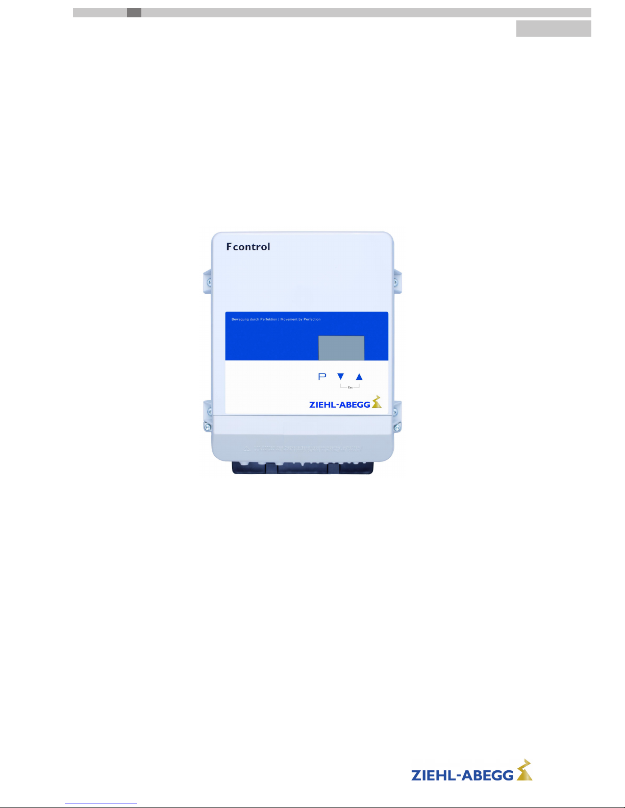
Fcontrol Basic
FSDM2.5..50AM
Frequency inverter with integrated sine lter for 3 ~ fans
Operating Instructions
Speed controller with 0...10 V input for presetting the fan speed
Keep for reference!
Software version: D2732A from Version 1.03
L-BAL-E174-GB 1704 Index 005
Part.-No.
english
CZ|D|E|F|FIN|GB|I|PL|RU|S|
☞
www.ziehlabegg.com
Page 2

Content
1 General notes . . . . . . . . . . . . . . . . . . . . . . . . . . . . . . . . . . . . . . . . . . . . . . . . . . . . . . . . . . . . . 5
1.1 Structure of the operating instructions . . . . . . . . . . . . . . . . . . . . . . . . . . . . . . . . . . . . . 5
1.2 Target group . . . . . . . . . . . . . . . . . . . . . . . . . . . . . . . . . . . . . . . . . . . . . . . . . . . . . . . . . 5
1.3 Exclusion of liability . . . . . . . . . . . . . . . . . . . . . . . . . . . . . . . . . . . . . . . . . . . . . . . . . . . 5
1.4 Copyright . . . . . . . . . . . . . . . . . . . . . . . . . . . . . . . . . . . . . . . . . . . . . . . . . . . . . . . . . . . 5
2 Safety instructions . . . . . . . . . . . . . . . . . . . . . . . . . . . . . . . . . . . . . . . . . . . . . . . . . . . . . . . . . 5
2.1 Intended use . . . . . . . . . . . . . . . . . . . . . . . . . . . . . . . . . . . . . . . . . . . . . . . . . . . . . . . . 5
2.2 Explanations of symbols . . . . . . . . . . . . . . . . . . . . . . . . . . . . . . . . . . . . . . . . . . . . . . . . 6
2.3 Product safety . . . . . . . . . . . . . . . . . . . . . . . . . . . . . . . . . . . . . . . . . . . . . . . . . . . . . . . 6
2.4 Requirements placed on the personnel / due diligence . . . . . . . . . . . . . . . . . . . . . . . . 6
2.5 Start-up and during operation . . . . . . . . . . . . . . . . . . . . . . . . . . . . . . . . . . . . . . . . . . . . 6
2.6 Work on the device . . . . . . . . . . . . . . . . . . . . . . . . . . . . . . . . . . . . . . . . . . . . . . . . . . . 7
2.7 Modifications / interventions in the device . . . . . . . . . . . . . . . . . . . . . . . . . . . . . . . . . . 7
2.8 Operator’s obligation of diligence . . . . . . . . . . . . . . . . . . . . . . . . . . . . . . . . . . . . . . . . . 7
2.9 Employment of external personnel . . . . . . . . . . . . . . . . . . . . . . . . . . . . . . . . . . . . . . . . 8
3 Product overview . . . . . . . . . . . . . . . . . . . . . . . . . . . . . . . . . . . . . . . . . . . . . . . . . . . . . . . . . . 8
3.1 Operational area . . . . . . . . . . . . . . . . . . . . . . . . . . . . . . . . . . . . . . . . . . . . . . . . . . . . . . 8
3.2 Functional description . . . . . . . . . . . . . . . . . . . . . . . . . . . . . . . . . . . . . . . . . . . . . . . . . . 8
3.3 Rating plate . . . . . . . . . . . . . . . . . . . . . . . . . . . . . . . . . . . . . . . . . . . . . . . . . . . . . . . . . 8
3.4 Maintenance . . . . . . . . . . . . . . . . . . . . . . . . . . . . . . . . . . . . . . . . . . . . . . . . . . . . . . . . . 8
3.5 Transport . . . . . . . . . . . . . . . . . . . . . . . . . . . . . . . . . . . . . . . . . . . . . . . . . . . . . . . . . . . 8
3.6 Storage . . . . . . . . . . . . . . . . . . . . . . . . . . . . . . . . . . . . . . . . . . . . . . . . . . . . . . . . . . . . . 9
3.7 Disposal / recycling . . . . . . . . . . . . . . . . . . . . . . . . . . . . . . . . . . . . . . . . . . . . . . . . . . . 9
4 Mounting . . . . . . . . . . . . . . . . . . . . . . . . . . . . . . . . . . . . . . . . . . . . . . . . . . . . . . . . . . . . . . . . . 9
4.1 General notes . . . . . . . . . . . . . . . . . . . . . . . . . . . . . . . . . . . . . . . . . . . . . . . . . . . . . . . . 9
4.2 Minimum space requirement . . . . . . . . . . . . . . . . . . . . . . . . . . . . . . . . . . . . . . . . . . . . 9
4.3 Fastening the device . . . . . . . . . . . . . . . . . . . . . . . . . . . . . . . . . . . . . . . . . . . . . . . . . . 10
4.4 Cable inlet . . . . . . . . . . . . . . . . . . . . . . . . . . . . . . . . . . . . . . . . . . . . . . . . . . . . . . . . . . 12
4.5 Outdoor installation . . . . . . . . . . . . . . . . . . . . . . . . . . . . . . . . . . . . . . . . . . . . . . . . . . . . 13
4.6 Installation location for agriculture . . . . . . . . . . . . . . . . . . . . . . . . . . . . . . . . . . . . . . . . 13
4.7 Temperature influences during commissioning . . . . . . . . . . . . . . . . . . . . . . . . . . . . . . . 13
5 Electrical installation . . . . . . . . . . . . . . . . . . . . . . . . . . . . . . . . . . . . . . . . . . . . . . . . . . . . . . . 13
5.1 Safety precautions . . . . . . . . . . . . . . . . . . . . . . . . . . . . . . . . . . . . . . . . . . . . . . . . . . . . 13
5.2 Terminal compartment . . . . . . . . . . . . . . . . . . . . . . . . . . . . . . . . . . . . . . . . . . . . . . . . . 14
5.3 EMC-compatible installation . . . . . . . . . . . . . . . . . . . . . . . . . . . . . . . . . . . . . . . . . . . . . 15
5.3.1 Motor cable . . . . . . . . . . . . . . . . . . . . . . . . . . . . . . . . . . . . . . . . . . . . . . . . . . . 15
5.3.2 Control cables . . . . . . . . . . . . . . . . . . . . . . . . . . . . . . . . . . . . . . . . . . . . . . . . . 15
5.3.3 Harmonics current for devices ≤ 16 A . . . . . . . . . . . . . . . . . . . . . . . . . . . . . . . . 15
5.3.4 Harmonics current and line impedance for devices > 16 A and ≤ 75 A . . . . . . . . . 15
5.4 Mains connection . . . . . . . . . . . . . . . . . . . . . . . . . . . . . . . . . . . . . . . . . . . . . . . . . . . . . 15
5.4.1 Line voltage . . . . . . . . . . . . . . . . . . . . . . . . . . . . . . . . . . . . . . . . . . . . . . . . . . . 15
5.4.2 Required quality attributes for the mains voltage . . . . . . . . . . . . . . . . . . . . . . . . . . 15
5.4.3 Line protection fuse . . . . . . . . . . . . . . . . . . . . . . . . . . . . . . . . . . . . . . . . . . . . . 16
5.4.4 Leakage current, securely attached, protective earth conductor . . . . . . . . . . . . . . 16
5.5 Residual-current-operated protective device . . . . . . . . . . . . . . . . . . . . . . . . . . . . . . . . . 16
5.6 Inverter output . . . . . . . . . . . . . . . . . . . . . . . . . . . . . . . . . . . . . . . . . . . . . . . . . . . . . . . 16
5.6.1 Motor connection . . . . . . . . . . . . . . . . . . . . . . . . . . . . . . . . . . . . . . . . . . . . . . . 16
5.6.2 Disconnection between controller and motor (repair switch) . . . . . . . . . . . . . . . . . 16
5.7 Motor protection . . . . . . . . . . . . . . . . . . . . . . . . . . . . . . . . . . . . . . . . . . . . . . . . . . . . . . 17
5.8 Analog input “E1” for setting fan speed . . . . . . . . . . . . . . . . . . . . . . . . . . . . . . . . . . . . 17
Operating Instructions Fcontrol Basic – model series FSDM2.5..50AM
L-BAL-E174-GB 1704 Index 005 Part.-No.
2/49
Page 3

5.9 Output voltage “10 V” . . . . . . . . . . . . . . . . . . . . . . . . . . . . . . . . . . . . . . . . . . . . . . . . . 19
5.10 Voltage supply for external devices (+24V, GND) . . . . . . . . . . . . . . . . . . . . . . . . . . . . . 19
5.11 Digital input “D1” for enable (device ON / OFF) . . . . . . . . . . . . . . . . . . . . . . . . . . . . . . 19
5.12 Relay outputs “K1” . . . . . . . . . . . . . . . . . . . . . . . . . . . . . . . . . . . . . . . . . . . . . . . . . . . . 19
5.13 Bypass circuit . . . . . . . . . . . . . . . . . . . . . . . . . . . . . . . . . . . . . . . . . . . . . . . . . . . . . . . . 19
5.14 Manual Bypass-Switch type S-D-25 and S-D-50 . . . . . . . . . . . . . . . . . . . . . . . . . . . . . 20
5.15 Potential at control voltage connections . . . . . . . . . . . . . . . . . . . . . . . . . . . . . . . . . . . . 20
6 Controls and Menu . . . . . . . . . . . . . . . . . . . . . . . . . . . . . . . . . . . . . . . . . . . . . . . . . . . . . . . . . 21
6.1 Multipurpose LC display and keyboard . . . . . . . . . . . . . . . . . . . . . . . . . . . . . . . . . . . . . 21
6.2 Menu structure . . . . . . . . . . . . . . . . . . . . . . . . . . . . . . . . . . . . . . . . . . . . . . . . . . . . . . . 21
7 Start-up . . . . . . . . . . . . . . . . . . . . . . . . . . . . . . . . . . . . . . . . . . . . . . . . . . . . . . . . . . . . . . . . . 22
7.1 Prerequisites for commissioning . . . . . . . . . . . . . . . . . . . . . . . . . . . . . . . . . . . . . . . . . . 22
7.2 Procedure for commissioning . . . . . . . . . . . . . . . . . . . . . . . . . . . . . . . . . . . . . . . . . . . . 22
8 Programming . . . . . . . . . . . . . . . . . . . . . . . . . . . . . . . . . . . . . . . . . . . . . . . . . . . . . . . . . . . . . 23
8.1 Menu group Setting . . . . . . . . . . . . . . . . . . . . . . . . . . . . . . . . . . . . . . . . . . . . . . . . . . . 23
8.2 Menu group Start . . . . . . . . . . . . . . . . . . . . . . . . . . . . . . . . . . . . . . . . . . . . . . . . . . . . . 24
8.3 Menu group Info . . . . . . . . . . . . . . . . . . . . . . . . . . . . . . . . . . . . . . . . . . . . . . . . . . . . . . 25
8.4 Controller Setup . . . . . . . . . . . . . . . . . . . . . . . . . . . . . . . . . . . . . . . . . . . . . . . . . . . . . . 25
8.4.1 Controlmode . . . . . . . . . . . . . . . . . . . . . . . . . . . . . . . . . . . . . . . . . . . . . . . . . . 25
8.4.2 Limit . . . . . . . . . . . . . . . . . . . . . . . . . . . . . . . . . . . . . . . . . . . . . . . . . . . . . . . . 26
8.4.3 LED Mode . . . . . . . . . . . . . . . . . . . . . . . . . . . . . . . . . . . . . . . . . . . . . . . . . . . . 26
8.4.4 PIN-Accesslevel . . . . . . . . . . . . . . . . . . . . . . . . . . . . . . . . . . . . . . . . . . . . . . . . 26
8.4.5 Wireless Communication . . . . . . . . . . . . . . . . . . . . . . . . . . . . . . . . . . . . . . . . . . 27
8.4.6 Min. Backlight . . . . . . . . . . . . . . . . . . . . . . . . . . . . . . . . . . . . . . . . . . . . . . . . . 27
8.5 Menu group IO Setup . . . . . . . . . . . . . . . . . . . . . . . . . . . . . . . . . . . . . . . . . . . . . . . . . . 27
8.5.1 Digital inputs “D1” (“E1” *) . . . . . . . . . . . . . . . . . . . . . . . . . . . . . . . . . . . . . . . . . 27
8.5.2 Relay outputs “K1” . . . . . . . . . . . . . . . . . . . . . . . . . . . . . . . . . . . . . . . . . . . . . . 28
8.5.3 Input “E1” . . . . . . . . . . . . . . . . . . . . . . . . . . . . . . . . . . . . . . . . . . . . . . . . . . . . 29
8.5.4 MODBUS communication watchdog . . . . . . . . . . . . . . . . . . . . . . . . . . . . . . . . . . 30
8.5.5 Networking via MODBUS . . . . . . . . . . . . . . . . . . . . . . . . . . . . . . . . . . . . . . . . . 30
8.6 Menu group “Motor Setup” . . . . . . . . . . . . . . . . . . . . . . . . . . . . . . . . . . . . . . . . . . . . . . 30
8.6.1 Setting motor rated current . . . . . . . . . . . . . . . . . . . . . . . . . . . . . . . . . . . . . . . . 30
8.6.2 Setting motor rated voltage . . . . . . . . . . . . . . . . . . . . . . . . . . . . . . . . . . . . . . . . 30
8.6.3 Adjustment of the U/f curve . . . . . . . . . . . . . . . . . . . . . . . . . . . . . . . . . . . . . . . . 31
8.6.4 Setting for Rampup time and Rampdown time . . . . . . . . . . . . . . . . . . . . . . . . . . . 32
8.6.5 Setting Rolling direct. . . . . . . . . . . . . . . . . . . . . . . . . . . . . . . . . . . . . . . . . . . . . 33
8.6.6 Setting Current limit . . . . . . . . . . . . . . . . . . . . . . . . . . . . . . . . . . . . . . . . . . . . . 33
8.6.7 Setting brake function . . . . . . . . . . . . . . . . . . . . . . . . . . . . . . . . . . . . . . . . . . . . 34
8.6.8 Motorheating . . . . . . . . . . . . . . . . . . . . . . . . . . . . . . . . . . . . . . . . . . . . . . . . . . 35
8.6.9 Overload detection . . . . . . . . . . . . . . . . . . . . . . . . . . . . . . . . . . . . . . . . . . . . . . 35
8.6.10 Ripple compensation . . . . . . . . . . . . . . . . . . . . . . . . . . . . . . . . . . . . . . . . . . . . 35
8.6.11 Rampdown limitation . . . . . . . . . . . . . . . . . . . . . . . . . . . . . . . . . . . . . . . . . . . . . 35
8.6.12 Suppression of speeds . . . . . . . . . . . . . . . . . . . . . . . . . . . . . . . . . . . . . . . . . . . 36
9 Parameter . . . . . . . . . . . . . . . . . . . . . . . . . . . . . . . . . . . . . . . . . . . . . . . . . . . . . . . . . . . . . . . . 37
9.1 Menu overview . . . . . . . . . . . . . . . . . . . . . . . . . . . . . . . . . . . . . . . . . . . . . . . . . . . . . . . 37
10 Diagnostics menu . . . . . . . . . . . . . . . . . . . . . . . . . . . . . . . . . . . . . . . . . . . . . . . . . . . . . . . . . 39
11 Events / Fault signals . . . . . . . . . . . . . . . . . . . . . . . . . . . . . . . . . . . . . . . . . . . . . . . . . . . . . . 40
11.1 Display and query of events and malfunctions . . . . . . . . . . . . . . . . . . . . . . . . . . . . . . . 40
11.2 Messages: Fcontrol / Icontrol Basic . . . . . . . . . . . . . . . . . . . . . . . . . . . . . . . . . . . . . . . 40
12 Enclosure . . . . . . . . . . . . . . . . . . . . . . . . . . . . . . . . . . . . . . . . . . . . . . . . . . . . . . . . . . . . . . . . 43
12.1 Technical data . . . . . . . . . . . . . . . . . . . . . . . . . . . . . . . . . . . . . . . . . . . . . . . . . . . . . . . 43
Operating Instructions Fcontrol Basic – model series FSDM2.5..50AM
L-BAL-E174-GB 1704 Index 005 Part.-No.
3/49
Page 4

12.1.1 Max. load dependent on ambient temperature and line voltage. . . . . . . . . . . . . . . . 44
12.2 Connection diagram . . . . . . . . . . . . . . . . . . . . . . . . . . . . . . . . . . . . . . . . . . . . . . . . . . . 45
12.2.1 Connection suggestion for several motors with motor protection units type STDT . . . 45
12.3 Dimensions [mm] . . . . . . . . . . . . . . . . . . . . . . . . . . . . . . . . . . . . . . . . . . . . . . . . . . . . . 46
12.4 Index . . . . . . . . . . . . . . . . . . . . . . . . . . . . . . . . . . . . . . . . . . . . . . . . . . . . . . . . . . . . . . 48
12.5 Manufacturer reference . . . . . . . . . . . . . . . . . . . . . . . . . . . . . . . . . . . . . . . . . . . . . . . . 49
12.6 Service information . . . . . . . . . . . . . . . . . . . . . . . . . . . . . . . . . . . . . . . . . . . . . . . . . . . . 49
Operating Instructions Fcontrol Basic – model series FSDM2.5..50AM
L-BAL-E174-GB 1704 Index 005 Part.-No.
4/49
Page 5

1 General notes
1.1 Structure of the operating instructions
Before installation and start-up, read this manual carefully to ensure correct use!
We emphasize that these operating instructions apply to specific units only, and are in no way valid for
the complete system!
Use these operating instructions to work safely with and on the device. They contain safety instructions that must be complied with as well as information that is required for failure-free operation of the
device.
Keep these operating instructions together with the device. It must be ensured that all persons that
are to work on the device can refer to the operating instructions at any time.
Keep the operating instructions for continued use. They must be passed-on to all successive owners,
users and final customers.
1.2 Target group
The operating instructions address persons entrusted with planning, installation, commissioning and
maintenance and servicing and who have the corresponding qualifications and skills for their job.
1.3 Exclusion of liability
Concurrence between the contents of these operating instructions and the described hardware and
software in the device has been examined. It is still possible that non-compliances exist; no guarantee
is assumed for complete conformity. To allow for future developments, construction methods and
technical data given are subject to alteration. We do not accept any liability for possible errors or
omissions in the information contained in data, illustrations or drawings provided.
ZIEHL-ABEGG SE is not liable for damage due to misuse, incorrect use, improper use or as a
consequence of unauthorized repairs or modifications.
1.4 Copyright
These operating instructions contain copyright protected information. The operating instructions may
be neither completely nor partially photocopied, reproduced, translated or put on data medium without
previous explicit consent from ZIEHL-ABEGG SE. Infringements are liable for damages. All rights
reserved, including those that arise through patent issue or registration on a utility model.
2 Safety instructions
This chapter contains instructions to prevent personal injury and property damage. These instructions
do not lay claim to completeness. In case of questions and problems, please consult our company
technicians.
2.1 Intended use
The equipment is to be used solely for the purposes specified and confirmed in the order.
Any other use above and beyond this is considered not for the intended purpose unless agreed
otherwise by contract. The manufacturer will not be liable for any damage resulting from this. The
individual or company using it bears the sole risk.
Reading these operating instructions and complying with all contained instructions - especially the
safety notifications contained therein - are considered part of intended use. To consider is also the
manual of attached components. Not the manufacturer, rather the operator of the device is liable for
any personal harm or material damage arising from non-intended use!
Operating Instructions Fcontrol Basic – model series FSDM2.5..50AM General notes
L-BAL-E174-GB 1704 Index 005 Part.-No.
5/49
Page 6
2.2 Explanations of symbols
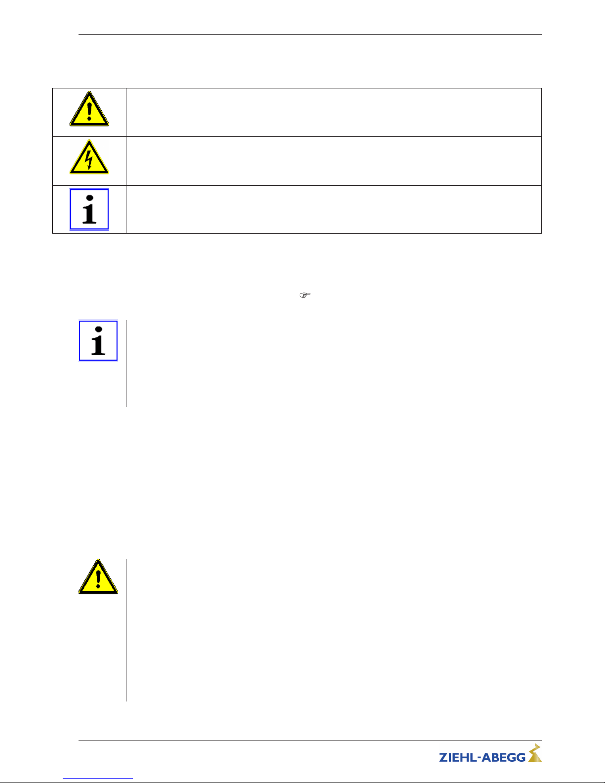
Safety instructions are highlighted with warning triangles and are depicted according to the degree of
hazard as follows.
Attention!
General hazardous area. Death or severe injury or significant property damage can occur if the
corresponding precautions are not taken!
Danger due to electric current
Danger by dangerous, electric voltage! Death or severe injury can occur if the corresponding
precautions are not taken!
Information
Important additional information and advice for user.
2.3 Product safety
The device conforms to the state of the art at the time of delivery and is fundamentally considered to
be reliable. The device and its accessories must only be used in a flawless condition and installed and
operated in compliance with the assembly instructions and/or operating instructions. Operating outside the device's technical specifications (
name plate and attachment / technical data) can lead to
a defect in the device and additional damage!
Information
In the case of a malfunction or a failure of the equipment check all functions with alarms in order to
prevent injury to persons or property. Note possibility of back-up operation. If used in intensive animal
environments, any malfunctions in the air supply must be detected as soon as possible to prevent the
development of a life-threatening situation for the animals. The design and installation of the system
must comply with local regulations and directives. In Germany these include DIN VDE 0100, the
animal protection and the keeping of working animals ordinance and the pig-keeping ordinance etc.
Also note the instructions of AEL, DLG, VdS.
2.4 Requirements placed on the personnel / due diligence
Persons entrusted with the planning, installation, commissioning and maintenance and servicing in
connection with the frequency inverter must have the corresponding qualifications and skills for these
jobs.
In addition, they must be knowledgeable about the safety regulations, EU/EC directives, rules for the
prevention of accidents and the corresponding national as well as regional and in-house regulations.
Personnel to be trained or instructed and apprentices are only permitted to work on the device under
the supervision of an experienced person. This also applies to personnel undergoing general training.
Comply with the legal minimum age.
2.5 Start-up and during operation
Attention!
•
During commissioning, unexpected and hazardous conditions can arise in the entire installation due
to defective adjustments, defective components or incorrect electrical connections. Remove all
persons and objects from the hazardous area.
•
During operation, the device must be closed or installed in a control cabinet. Fuses may only be
replaced by new ones and must not be repaired or bypassed. The data for the maximum line fuse
are to be considered absolutely (see Technical data). Use only fuses specified in schematic
diagrams.
•
Any faults detected in the electric system/modules/operating equipment must be corrected
immediately. If these faults are not corrected, the device/system is potentially very dangerous. The
device/system must therefore not be operated when it is faulty.
•
Pay attention to smooth, low vibration running of the motor/fan, the appropriate instructions in the
drive documentation must be observed!
Operating Instructions Fcontrol Basic – model series FSDM2.5..50AM Safety instructions
L-BAL-E174-GB 1704 Index 005 Part.-No.
6/49
Page 7
2.6 Work on the device
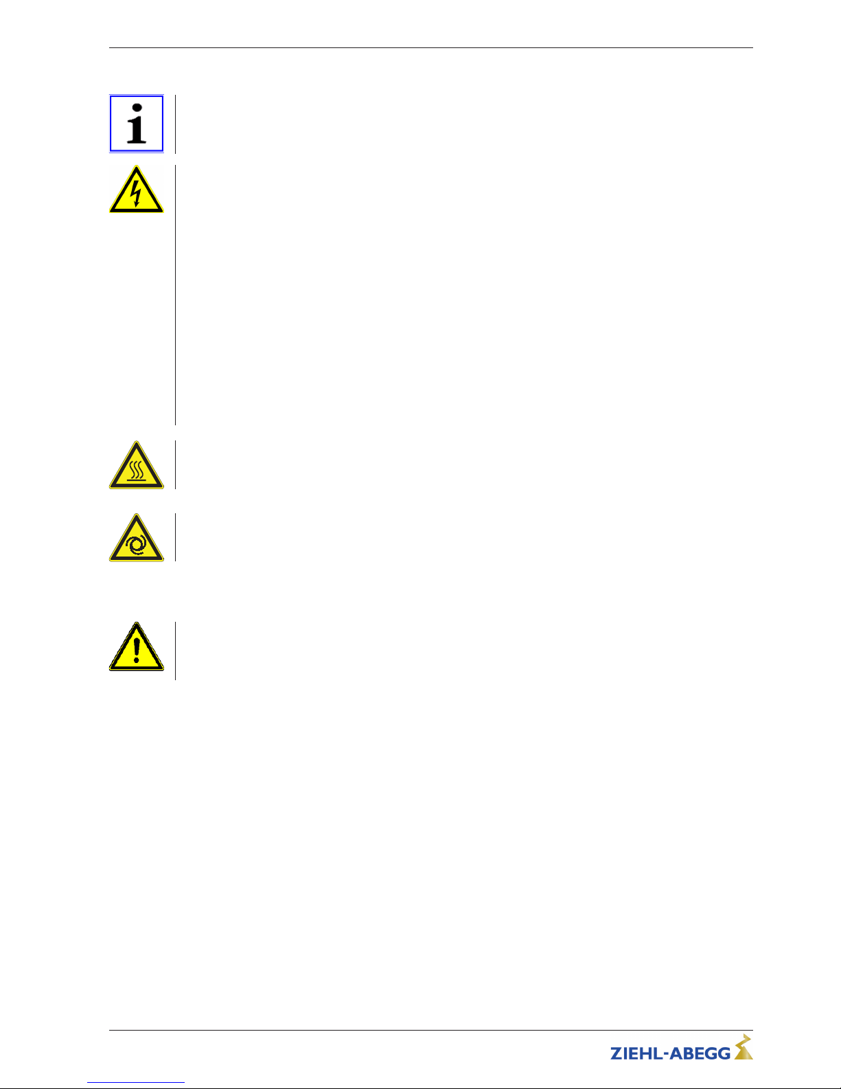
Information
Mounting, electrical connection, and start-up operation may only be carried out by an electrical
specialist in accordance with electrotechnical regulations (e.g. EN 50110 or EN 60204)!
Danger due to electric current
•
It is generally forbidden to carry out work on electrical live parts. Protection class of the device when
open is IP00! It is possible to touch hazardous voltages directly.
•
The safe isolation from the supply must be checked using a two-pole voltage detector.
•
Even after disconnecting the mains voltage, life-threatening charges can appear between the
protective ground “PE” and the mains connection.
•
The protective earth is conducting high discharge currents (dependent on the switching frequency,
current-source voltage and motor capacity). Earthing in compliance with EN specifications shall
therefore be observed even for testing and trial conditions (EN 50 178, Art. 5.2.11). Without
earthing, dangerous voltages can be present on the motor housing.
Waiting period at least 3 minutes!
•
Through use of capacitors, danger of death exists even after switching off the device through
directly touching the energized parts or due to parts that have become energized due to faults.
•
It is only permitted to remove the housing cover after waiting for 3 minutes once the line supply
cable has been shut down. Should measurement or adjustment work be unavoidable on the opened
unit while still powered, then this may only be performed by qualified personnel acquainted with the
thereby associated hazards.
Attention!
Even after switching off, dangerous temperatures can still occur in and on the device.
Attention!
Automatically restart after a power failure or mains disconnection!
2.7 Modifications / interventions in the device
Attention!
For reasons of safety, no unauthorized interventions or modifications may be made on the device. All
planned modifications must be authorized by the manufacturer in writing.
Use only genuine spare parts / genuine wearing parts / genuine accessories from ZIEHL-ABEGG.These parts were specifically designed for the device. There is no guarantee that parts from non-original
sources are designed and manufactured in correspondence with load and safety requirements.
Parts and optional equipment not supplied by ZIEHL-ABEGG are not approved by ZIEHL-ABEGG for
use.
2.8 Operator’s obligation of diligence
•
The contractor or owner must also ensure that the electric systems and equipment are operated
and maintained in accordance with electro-technical regulations.
•
The owner is obliged to ensure that the device is operated in perfect working order only.
•
The device may only be used as intended (see “Application”).
•
You must periodically examine the safety equipment for their properly functioning condition.
•
The assembly instructions and/or operating instructions are always readily available at the location
where the device is being used, are complete and are in legible condition.
•
These persons are regularly instructed in all applicable questions regarding occupational safety
and environmental protection and are knowledgeable regarding the assembly instructions and/or
operating instructions and, especially, are familiar with the safety instructions contained therein.
•
All safety and warning notices attached to the device are never removed and remain legible.
Operating Instructions Fcontrol Basic – model series FSDM2.5..50AM Safety instructions
L-BAL-E174-GB 1704 Index 005 Part.-No.
7/49
Page 8
2.9 Employment of external personnel
Maintenance and service work are frequently carried out by external employees who often do not
recognize the specific situations and the thus resulting dangers.These persons must be comprehensively informed about the hazards in their area of activity.
You must monitor their working methods in order to intervene in good time if necessary.
3 Product overview
3.1 Operational area
Frequency inverter designed for a stepless control of fans without additional (electromagnetic) motor
noise.
By using the integrated all-pole effective Sine filter (phase to phase and phase to ground), an absolute
parallel control of fans without risk of damage for motors is possible. Screened motor cables not
required!
Only suitable for drives with low set-off torque (e.g.: fans or pumps).
3.2 Functional description
The frequency inverters of these series generate their 3~ output with variable voltage and frequency
from the three-phase mains on the input.
The devices are constructed in accordance with the general requirement in EN 61800-2 for adjustable
speed electrical power systems and is intended for one-quadrantdrives.
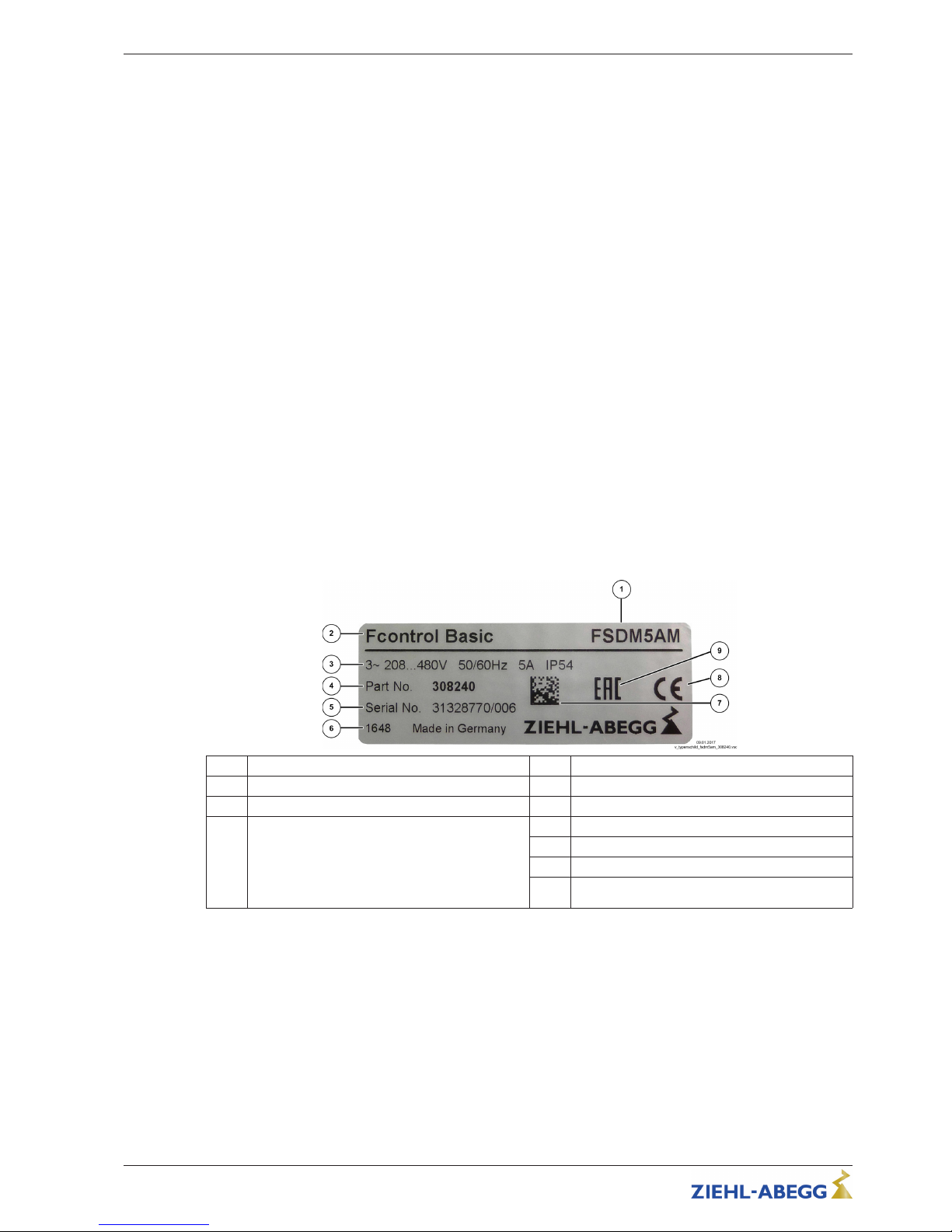
3.3 Rating plate
The name plate carries the technical data valid for the delivered product.
Example for name plate
no. Description no. Description
1 Type designation 4 Part no.
2 ZIEHL-ABEGG brand name 5 Serial number
3 Type of voltage
Line voltage
Mains frequency
Rated current (output)
Protection class
6 Production code
7 DATA MATRIX code serial number
8 European mark of conformity
9 Eurasian mark of conformity
3.4 Maintenance
The device must be checked for soiling and, if necessary, cleaned in periodic intervals.
3.5 Transport
•
The device is packed ex factory to suit the transport method previously agreed.
•
Always use the original packaging materials when transporting the device.
•
Avoid shocks and impacts to the device during the transport.
•
During manual handling the human lifting and carrying restrictions must be observed and adhered
to.
Operating Instructions Fcontrol Basic – model series FSDM2.5..50AM Product overview
L-BAL-E174-GB 1704 Index 005 Part.-No.
8/49
Page 9
3.6 Storage
•
The device must be stored in its original packaging in a dry and weather-proof room.
•
Avoid exposure to extreme heat and cold.
•
Avoid prolonged storage; we recommend a maximum of one year (consult the manufacturer before
starting if stored for longer).
3.7 Disposal / recycling
Disposal must be carried out professionally and in an environmentally friendly way in accordance with
the respective national legal stipulations.
" Separate the materials by type and in an environmentally friendly way.
" If necessary, commission a specialist company with the waste disposal.
4 Mounting
4.1 General notes
Attention!
The following points must be complied with during the mechanical installation to avoid causing a defect
in the device due to assembly errors or environmental influences:
•
Before installation remove the device from the packing and check for any possible shipping
damage! Start-up is not allowed in the case of transport damage!
•
At a weight greater than 25 kg for men / 10 kg for women, the device should be lifted out by two
persons (according to REFA). The values may differ from country to country.
•
Wear safety shoes and gloves for handling!
•
Assemble the device on a clean and stable base. Do not distort during assembly! Use the
appropriate mounting devices for proper installation of the unit!
•
A mounting on vibrating base is not permissible, if no data to the vibration strength is made (see
Technical data)!
•
When mounted onto lightweight walls, there must be no impermissibly high vibrations or shock
loads. Any banging shut of doors that are integrated into these lightweight walls, can result in
extremely high shock loads. Therefore, we advise you to decouple the devices from the wall.
•
Do not allow drilling chips, screws and other foreign bodies to reach the device interior!
•
Maintain the stated minimum clearances to ensure unobstructed cooling- air feed as well as
unobstructed outgoing air discharge (
minimum space requirement)!
•
The device should be installed in a location where it will not be disturbed, but at the same time can
be easily accessed!
•
Care must be taken to avoid direct radiation from the sun!
•
The device is designed for vertical installation (cable inlet down). A horizontal or reclined installation
is only permissible after technical release of the manufacturer!
•
Be sure to observe proper heat dissipation (see Technical data, heat dissipation).
4.2 Minimum space requirement
In order to ensure sufficient ventilation of the device, clearance on all sides of at least 50 mm has to
be maintained to the housing walls, switch cabinet doors, wiring ducts, etc. The same clearance
applies to the installation of several devices next to each other.
When installing several devices on top of each other, the danger of reciprocal heating exists. This
layout is only then permissible when the air suctioned from the upper unit does not become warmer
than the permissible ambient temperature (see Technical data). I.e., a correspondingly larger clearance or thermal shielding is required.
Operating Instructions Fcontrol Basic – model series FSDM2.5..50AM Mounting
L-BAL-E174-GB 1704 Index 005 Part.-No.
9/49
Page 10
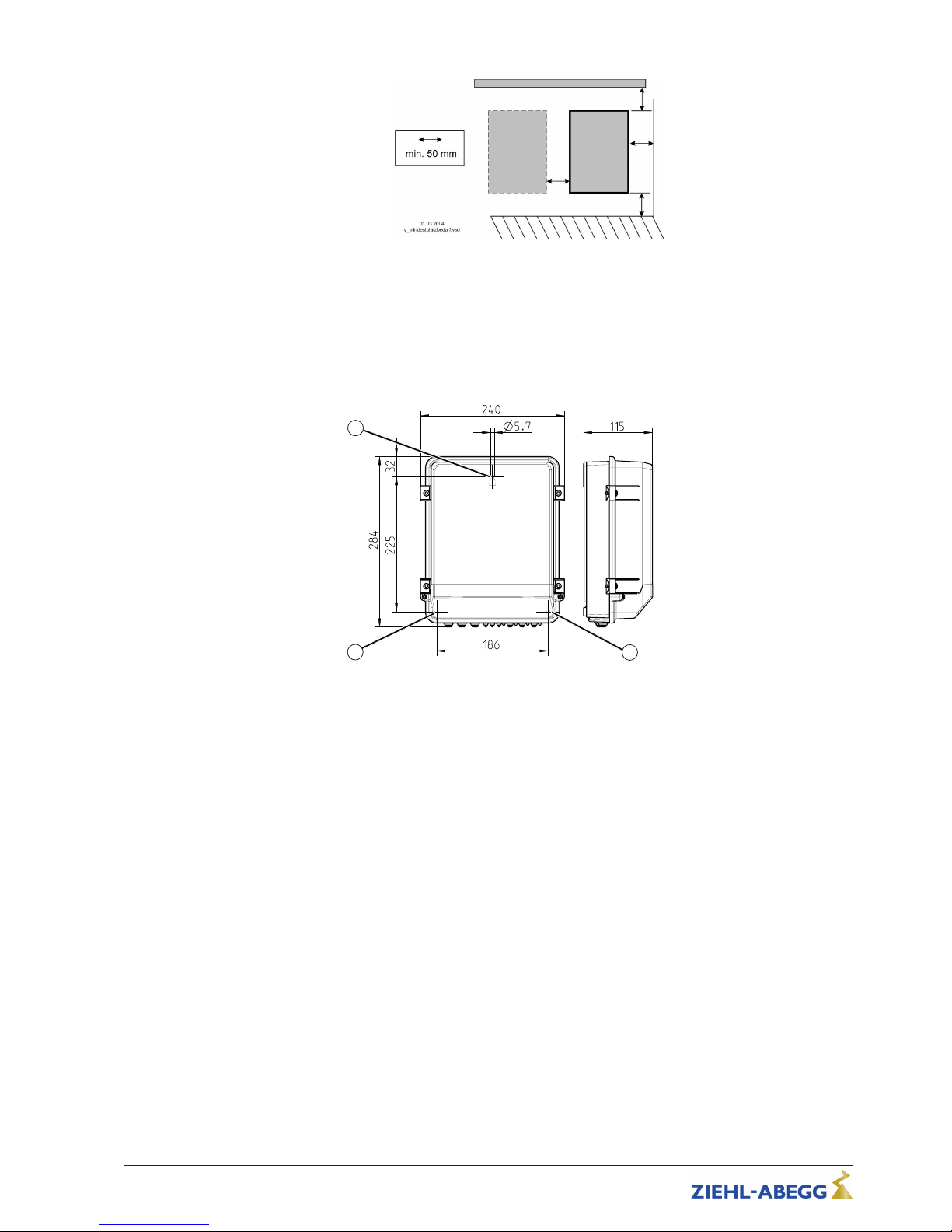
4.3 Fastening the device
The type of fastening and the number of fastening points are dependent on the housing design. All the
fastening points available must be used for safe fastening.
Proceed as follows:
Type FSDM2.5M
Fastening at 3 points
GM00006A_M
15.12.2015
3
2
1
" Drill fastening point “1”.
" Screw in flat-head screw up to a distance of approx. 2 mm and mount the device.
" Remove the terminal compartment cover.
" Align the device and mark the position of both lower fastening points “2” + “3”.
" Remove the device and drill the fastening points “2” + “3”.
" Remount the device and tighten the fastening point screws “2” + “3”.
Operating Instructions Fcontrol Basic – model series FSDM2.5..50AM Mounting
L-BAL-E174-GB 1704 Index 005 Part.-No.
10/49
Page 11
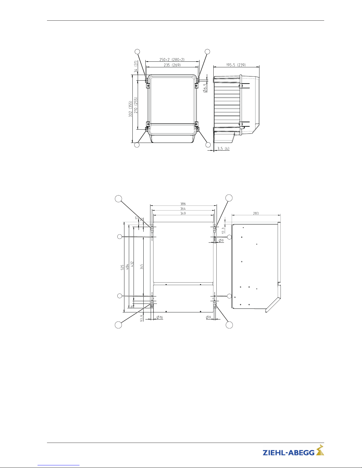
Type FSDM5...16M (FSDM22M)
Fastening at 4 points
GM00005A_M
15.12.2015
1 2
4
3
" Drill fastening points “1” - “4”.
" Fasten device with screws.
Type FSDM32...50M
Fastening at 8 points
GM00002A_M
15.12.2015
1
7
2
34
5
6
8
" Drill 8 fastening points.
" Screw in fastening point screws “1” - “4” up to a distance of approx. 5 mm and mount the device.
" Tighten fastening point screws “1” - “4”
" Screw in fastening point screws “5” - “8” and tighten.
Operating Instructions Fcontrol Basic – model series FSDM2.5..50AM Mounting
L-BAL-E174-GB 1704 Index 005 Part.-No.
11/49
Page 12
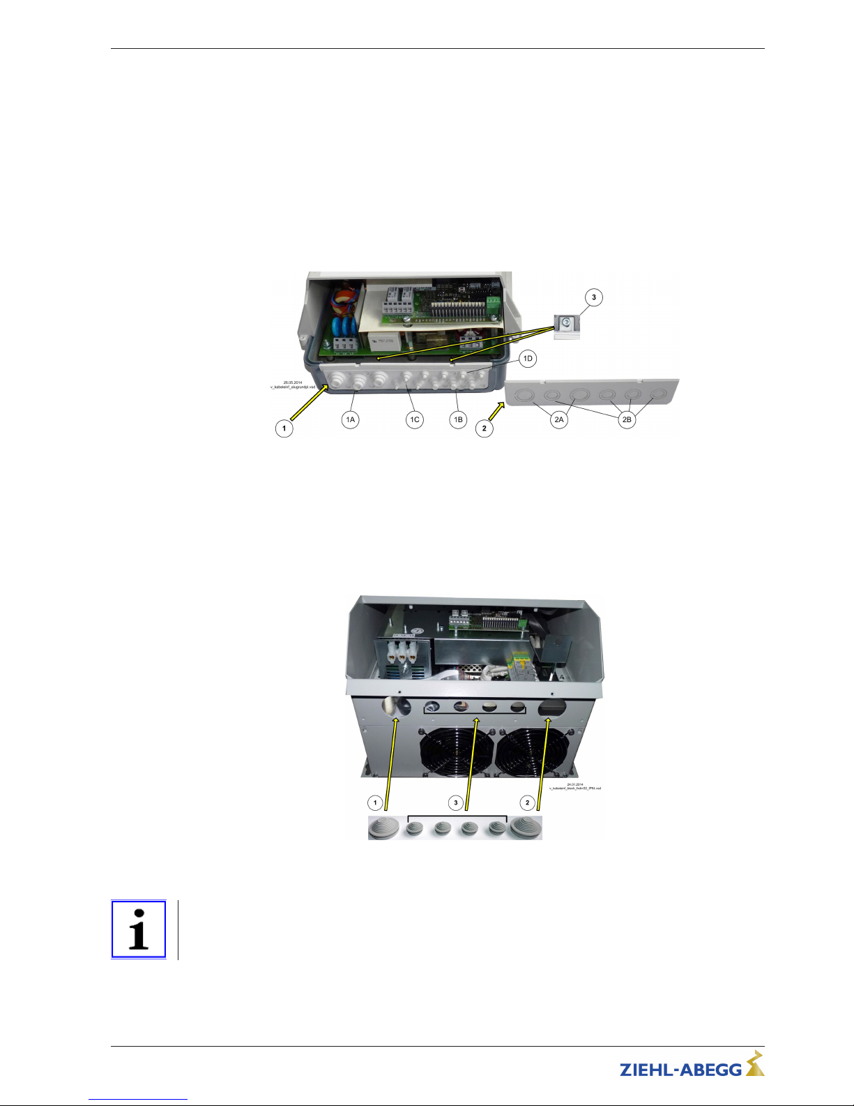
4.4 Cable inlet
Proceed as follows:
" Remove the terminal compartment cover.
" Depending on the housing model cut off necessary cable inlets respectively to the cable diameter.
Or alternative use cable inlet for cable glands. Metal sheet housings are supplied with stoppers.
Any cable ducts openings not used must be sealed!
" Strip and insert the cables properly.
" Attach cover for terminal compartment again carefully before start-up.
Housing with aluminum base plate
1 Cable inlet with step nozzles (factory installed)
1A 3 x max. 18 mm
1B 3 x max. 14 mm
1C 3 x max. 11 mm
1D 4 / 8 x max. 8 mm
2 attached cable inlet for cable glands
2A 17 / 21 mm
2B 12.5 / 17 mm
3 Fastening screws
Sheet metal housing
1 Inlet mains connection (40 mm)
2 Inlet motor connection (40 mm)
3 Inlet control cables (20 mm)
Information
•
Cable glands can be used alternatively (not included in delivery). The manufacturer’s specifications
for tightening torque and sealing area must be observed!
•
Openings which are not needed must be sealed!
Operating Instructions Fcontrol Basic – model series FSDM2.5..50AM Mounting
L-BAL-E174-GB 1704 Index 005 Part.-No.
12/49
Page 13
4.5 Outdoor installation
Outdoor installation is possible up to -20 °C when the controller supply is not switched off. Installation
must be protected from the effects of weather as much as possible, including protection from direct
sunlight!
4.6 Installation location for agriculture
When using for animal keeping, do not install the device directly in the stable but in a separate room
with a lower pollutant load. This helps to avoid damages caused by pollutant gases (e.g. ammonia
fumes, hydrogen sulphide fumes).
4.7 Temperature influences during commissioning
Avoid condensation in the controller and functional faults attributable to condensation by storing the
controller at room temperature!
5 Electrical installation
5.1 Safety precautions
Danger due to electric current
•
Work on electric components may only be carried out by trained electricians or by persons
instructed in electricity under the supervision of an electrician in accordance with electrical
engineering regulations.
•
The 5 electrical safety rules must be observed!
•
It is forbidden to carry out work on electrically live parts. Even after disconnection, the dc-link is still
live. Always wait at least 3 minutes.
•
Cover neighbouring electrical equipment during installation work.
•
Other measures may be necessary to achieve safe electrical isolation.
•
A second person must always be present when working on energized parts or lines who
disconnects in case of emergency.
•
Inspect electrical equipment periodically: retighten loose connections – immediately replace
damaged lines and cables.
•
Always keep switch cabinets and all electrical supply facilities locked. Access is only allowed for
authorized persons using a key or special tool.
•
Operating the device with the housing cover removed is prohibited because energized, exposed
parts are present inside the device. Disregarding this regulation can lead to severe personal injury.
•
For metal cable inlets the necessary protective earth connection to the bottom of the housing is
made by screws. The device may only be started up when these screws are fitted properly.
•
The required protective earth connection is established using screws between the housing parts in
metal terminal space covers and housing casings. Commissioning is only permissible after these
screws have been properly attached!
•
Metal screwed-connections are not permitted in plastic housing parts because there is no potential
equalization.
•
The device owner is responsible for the EMC of the entire plant according to the locally applicable
standards.
•
Never clean electrical equipment with water or similar liquids.
Information
The respective connections are represented in the enclosure of this manual ( Connection diagram)!
Operating Instructions Fcontrol Basic – model series FSDM2.5..50AM Electrical installation
L-BAL-E174-GB 1704 Index 005 Part.-No.
13/49
Page 14
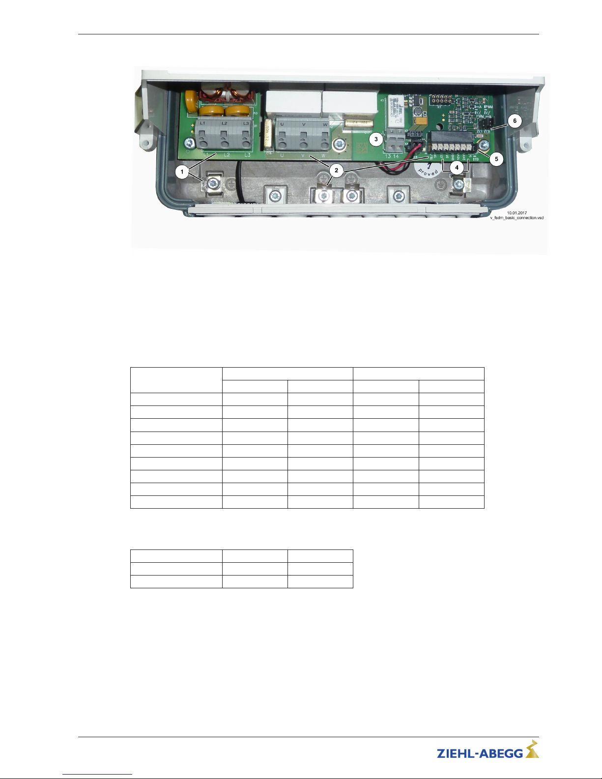
5.2 Terminal compartment
Example: Position of terminals for devices with aluminum base plate
1 Line
2 Motor
3 Indication relays
4 Modulation
5 Jumper J1 for thermal protector TB/TP
6 Jumper E1.1/E1.2 for speed setting signal
Maximum cross sections of terminals for power section
Type
Line Motor
rigid flexible rigid flexible
F(S)DM2.5(A)M
4 mm
2
2.5 mm
2
4 mm
2
2.5 mm
2
F(S)DM5(A)M
4 mm
2
2.5 mm
2
4 mm
2
2.5 mm
2
F(S)DM8(A)M
4 mm
2
2.5 mm
2
4 mm
2
2.5 mm
2
F(S)DM10(A)M
4 mm
2
2.5 mm
2
4 mm
2
2.5 mm
2
F(S)DM16(A)M
4 mm
2
2.5 mm
2
4 mm
2
2.5 mm
2
F(S)DM22(A)M
6 mm
2
6 mm
2
6 mm
2
6 mm
2
F(S)DM32(A)M
16 mm
2
10 mm
2
10 mm
2
6 mm
2
F(S)DM40(A)M
25 mm
2
16 mm
2
16 mm
2
10 mm
2
F(S)DM50(A)M
25 mm
2
16 mm
2
16 mm
2
10 mm
2
Possible cross sections of terminals for control section
For all types
rigid flexible
Modulation 0.25 - 1.5 mm
2
0.25 - 1.5 mm
2
Indication relays 0.08 - 2.5 mm20.08 - 2.5 mm
2
Operating Instructions Fcontrol Basic – model series FSDM2.5..50AM Electrical installation
L-BAL-E174-GB 1704 Index 005 Part.-No.
14/49
Page 15
5.3 EMC-compatible installation
5.3.1 Motor cable
The applicable standard for interference emissions is EN 61000-6-3. Compliance with this standard is
achieved through the use of an unscreened motor feed cable.
5.3.2 Control cables
Pay attention to sufficient distance from powerlines and motor wires to prevent interferences. The
control cable may not be longer than 30 m. Screened control cables must be used when the cable
length is longer than 20 m. When using a shielded cable connect the shielding to one side only, i.e.
only to the control unit with the protective ground (keep cable short and with as little inductance as
possible!).
5.3.3 Harmonics current for devices ≤ 16 A
According to EN 61000-3-2 these devices are to be classified as “professional” devices.
Connection to a low voltage supply (public networks) is allowed insofar as this has been clarified with
the respective energy supply company responsible.
5.3.4 Harmonics current and line impedance for devices > 16 A and ≤ 75 A
Extract from EN 61000-3-12, valid for equipments with rated current > 16 A and ≤ 75 A, connected to
public low-voltage systems.
This equipment complies with IEC 61000-3-12 provided that the short-circuit power S
SC
is greater than or equal
to R
SCE
x S
equ
at the interface point between the user's supply and the public system.
It is the responsibility of the installer or user of the equipment to ensure, by consultation with the distribution
network operator if necessary, that the equipment is connected only to a supply with a short-circuit power S
SC
greater than or equal to R
SCE
x S
equ
.
S
SC
Short-circuit power from line at the interface point between the user's supply and the public system
S
equ
Rated - apparent power for three phase devices: S
equ
= √3 x UI x I
equ
(UI = phase to phase voltage Technical data “Line voltage”)
(I
equ
= rated current of the device Technical data “Rated current input”)
R
SCE
Short-circuit ratio
For this devices: R
SCE
≥ 120
5.4 Mains connection
5.4.1 Line voltage
Power from the mains is connected to terminals: PE, L1, L2, L3 and N (depending on type). Here, it
must be strictly observed that the mains voltage lies within the allowable tolerance specifications (
Technical data and nameplate affixed to the side).
The neutral conductor connection “N” is only available for the device types with 22 A/25 A rated
current for the reduction of the leakage current. It is irrelevant for the device’s functionality, for those
supply networks without neutral conductors the connection is not required. Because however, higher
leakage currents can flow through the “PE” conductor connection, undesirable erroneous activation
may occur on systems equipped with RCD circuit breakers.
Danger due to electric current
Not suitable for IT system!
Do not operate on Grounded Delta System!
5.4.2 Required quality attributes for the mains voltage
Danger due to electric current
The mains voltage must comply with the EN 50160 quality characteristics and the defined standard
voltages in IEC 60038!
Operating Instructions Fcontrol Basic – model series FSDM2.5..50AM Electrical installation
L-BAL-E174-GB 1704 Index 005 Part.-No.
15/49
Page 16
5.4.3 Line protection fuse
The mains connection must be fused depending on the used cable, the type of routing, the operating
conditions and according to the standards applicable on site. The specification for the maximum
admissible line fuse of the device must be observed (see technical data).
Possible components for the line protection (recommendation):
•
Safety fuses of operating class “gG” (whole range fuse cartridges for general applications according
to EN 60269-1).
•
Line protection switch with characteristic “C” (according to EN 60898-1).
•
Motor protection switch with overload and short-circuit trigger (according to EN 60947-4-1). Setting
overcurrent trigger to maximum permissible current of the line.
5.4.4 Leakage current, securely attached, protective earth conductor
Danger due to electric current
The maximum leakage current depends on the type of device and the connected mains voltage (
Technical Data). With regard to fixed connection and the type of PE conductor connection, the
specification for the leakage current must be observed under consideration of the locally valid
standards (for Europe
EN 50178 Section 5.2.11 or 5.3.2.1 etc.).
Minimum cross-section for PE conductor for fixed connection = 1.5 mm
2
!
5.5 Residual-current-operated protective device
Danger due to electric current
For an installation of r.c.d. protection, it shall be observed that this must be of “universal-current
sensitivity” (Type B). In accordance with EN 50 178, Section. 5.2. other types of current-operated
protective devices may not be used. To ensure as high a degree of reliability as possible , we
recommend a tripping current of 300 mA.
5.6 Inverter output
5.6.1 Motor connection
The motor leads are connected to the terminals: PE, U, V, W. Several fans can be connected to the
controller-the maximum total current of all motors must not exceed the current rating for the controller.
Information
•
It is recommended that a separate motor protection unit be foreseen for each fan.
•
For motors with thermistors “TP” (PTC thermistor) e.g. type U-EK230E
•
For motors with thermostats “TB” (thermal contacts) e. g. type STDT16 or AWE-SK (
Enclosure:
Connection suggestion for several motors with motor protection unit type STDT.)
5.6.2 Disconnection between controller and motor (repair switch)
Ideally, a repair switch should be installed before the controller (supply line disconnect).
In the case of complete disconnection (entire load) after the controller, the enable (controller OFF /
ON) must be disconnected simultaneously. I.e., an additional control contact is needed. Switching on
the motor while simultaneously issuing the enable (ON) achieves secure energizing with low
saturation of the controller.
Attention!
When switching on the motor plus existing release: under certain circumstances, this can occur under
full modulation of the controller.
Operating Instructions Fcontrol Basic – model series FSDM2.5..50AM Electrical installation
L-BAL-E174-GB 1704 Index 005 Part.-No.
16/49
Page 17
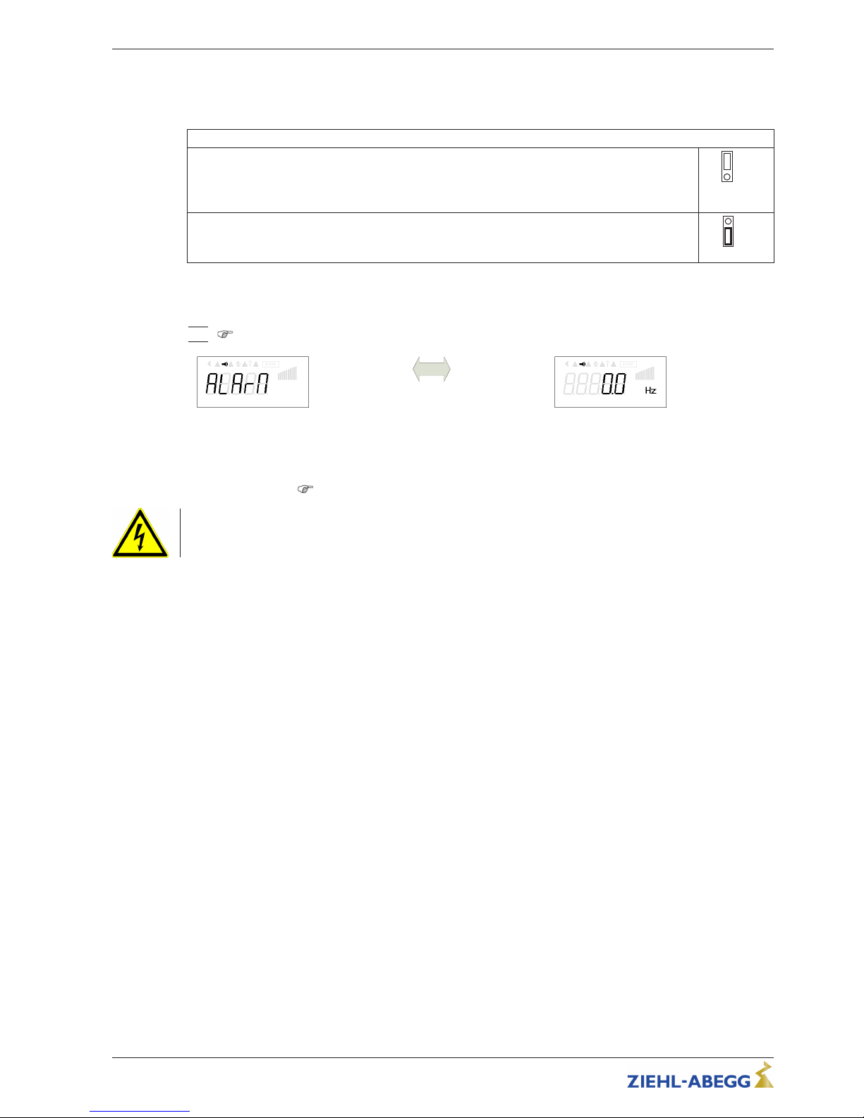
5.7 Motor protection
Motor protectionis possible by connecting thermostats “TB” (thermal contacts) or thermistors “ TP”
(PTC).
The jumper “J1” in the connection space must be plugged according to the used thermal protectors.
Motor with thermistors “TP”
For motor with thermistors “TP” the jumper “J1” must be plugged at the top.
A maximum of six individual thermistors (DIN 44081 or DIN 44082) may be connected in series to
a single device.
J1
TP
Motor with thermostats “TB”
For motor with thermostats “TB” jumper plugged at bottom (factory setting).
J1
TB
When a connected thermostat or thermistor responds (interruption between the two terminals
“TB/TP”) the device switches off and does not switch back on.
Relais “K1” is de-energized, terminals “13” - “14” interrupted. The internal signal lamp flashes in code
|15|
( Diagnostics / faults).
Mo tor fa ul t
Display actual-value alternates with an
alarm message
Fr equ en cy
Possibilities for re-starting after the drive has cooled down terminals “TB/TP” bridged by:
•
By switching the mains voltage off and then on again.
•
Via a digital input for remote control (ON/OFF enable).
•
Function “Reset
”
Menu group “Start”
Danger due to electric current
An outside voltage may never be connected to the terminals “TB/TP” and/or!
5.8 Analog input “ E1” for setting fan speed
The device has an analog input for setting the fan speed. Connection “E1” / “GND” (Analog In 1).
The internal jumpers “E1.1” and “E1.2” are factory set in the position for a 0...10 V speed setting
signal.
The appropriate jumper positions must be observed for a 0...20 mA signal or a PWM signal.
Operating Instructions Fcontrol Basic – model series FSDM2.5..50AM Electrical installation
L-BAL-E174-GB 1704 Index 005 Part.-No.
17/49
Page 18
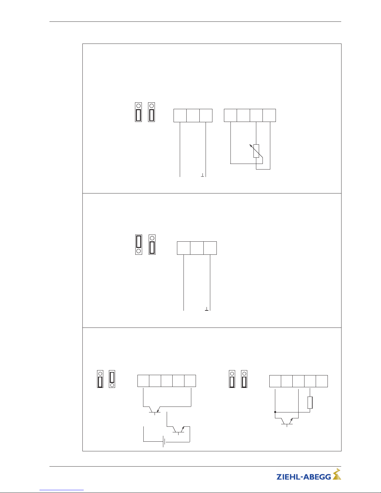
Possibilities for speed setting
0...10 V (factory setting)
Control via external setting signal 0...10 V
or
Speed setting by external potenziometer (10 kΩ) at terminals “+10 V” and “GND” pick of-off at terminal “E1”.
E1 D1 GND
0...10 V
+
Analog In 1
E1,1 E1,2
V
E1 D1 GND 10V
Analog In 1
10 V DC Out
10 kΩ
30.08.11
i_jumper_if_basic_0_10v.eps
0...20 mA
Control via external setting signal 0...20 mA
E1
D1 GND
0...20 mA
+
Analog In 1
E1,1 E1,2
mA
31.01.12
i_jumper_if_basic_0_20
0...100 % PWM
Control via external setting signal PWM
E1,1
E1,2
PWM
E1
D1 GND
10V
Analog In 1
10 V DC Out
31.01.12
i_jumper_if_basic_pwm.eps
24V
24 V DC Out
24 V
15...28 V
+
-
GND
E1
E1,1
E1,2
PWM
(10 V)
E1
D1 GND
10V
Analog In 1
10 V DC Out
24V
24 V DC Out
PWM
f = 1...10 kHz
10 kΩ
Operating Instructions Fcontrol Basic – model series FSDM2.5..50AM Electrical installation
L-BAL-E174-GB 1704 Index 005 Part.-No.
18/49
Page 19
Danger due to electric current
•
Do not replug the jumper under voltage, observe the safety instructions!
•
Make sure the signal has the correct polarity!
•
Never apply line voltage to analog inputs!
5.9 Output voltage “10 V”
Voltage supply e.g. for speed setting by external potentiometer.
Connection: “10 V” - “GND” (max. load
Technical data und connection diagram).
•
It is not permissible to connect voltage outputs of several devices to each other!
•
It is not permissible to connect voltage outputs in the device to each other!
5.10 Voltage supply for external devices (+24V, GND)
A voltage supply is integrated for external devices e.g. a sensor (max. current load see technical
data).
In case of overload or short circuit (24 V – GND), the external power supply is shut down (multi-fuse).
The device performs a “Reset” and continues operation.
•
It is not permissible to connect voltage outputs of several devices to each other!
•
It is not permissible to connect voltage outputs in the device to each other!
5.11 Digital input “D1” for enable (device ON / OFF)
Electronic disconnection and Reset after motor fault via floating contact at terminals “D1”- “24V (input
resistance and voltage range
Technical data)”.
Function factory setting for “D1”:
•
Device “ON” for closed contact.
•
Device “OFF” with opened contact.
Activation via floating contacts, a low voltage of approx. 24 V DC is connected.
Danger due to electric current
•
No disconnection (no potential isolation in accordance with VBG4 §6) in remote control of the
device!
•
Never apply line voltage to the digital input!
5.12 Relay outputs “K1”
An external fault indicator is available over the potential-free contact of the built-in relays (max. contact
rating
Technical data and connection diagram).
Function factory setting for “K1”:
•
For operation the relay is energized, connections “13” and “14” are bridged. For fault the relay is deenergized (
Diagnostics / faults).
•
When switching off via enable (D1 = Digital In 1), the relay remains energized.
5.13 Bypass circuit
Please observe the following during bypass switching (controller shunt with mains voltage):
•
Mutual locking of mains contactor and bypass protection.
•
Time delay of at least 1 second during switching.
•
When the contactor is switched off at the inverter output, the “enable” (ON / OFF) must also be
opened and closed again when it is switched back on. When switching off, wait at least 90 seconds
before switching back on!
•
Never apply line voltage to the inverter output!
Operating Instructions Fcontrol Basic – model series FSDM2.5..50AM Electrical installation
L-BAL-E174-GB 1704 Index 005 Part.-No.
19/49
Page 20
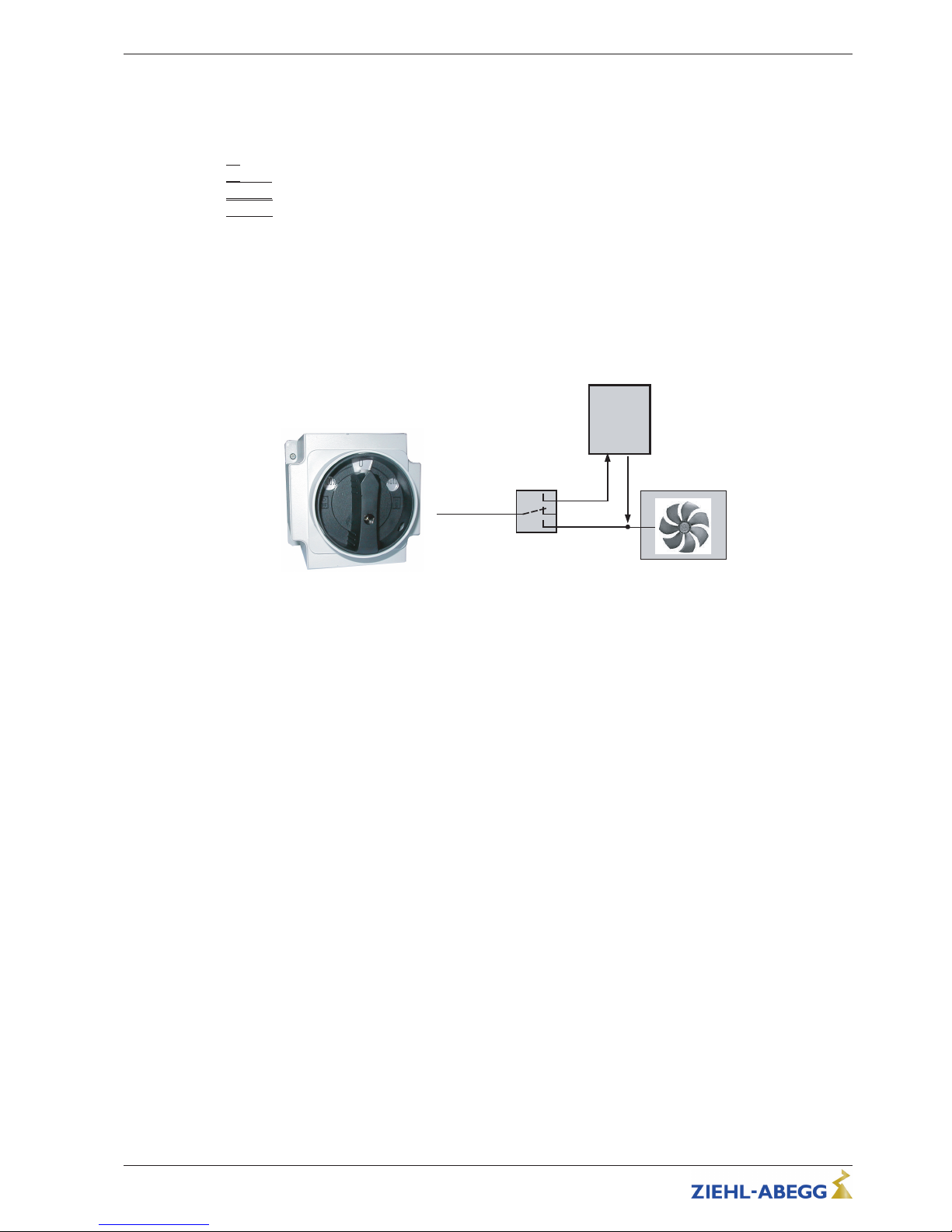
5.14 Manual Bypass-Switch type S-D-25 and S-D-50
As accessories are manual main switches with bypass function available.
By switching OFF Frequency inverters necessary waiting period before renewed switching on
amounts minimum 90 seconds!
Switch position
•
|0|
= Switch OFF supply line (lockable)
•
|
AUTO| = Operation Control
•
|
100 %| = Operation Bypass (controller without supply)
Technical data
•
Line voltage max. 690 V, 50/60 Hz
•
Rated current
– Type S-D-25 Part.-No. 349035: 25 A
– Type S-D-50 Part.-No. 349040: 50 A
•
Dimensions w x h x d [mm]
– Type S-D-25: 115 x 115 x 163
– Type S-D-50: 135 x 135 x 188
•
Protection class IP65
S-D-25
AUTO
0
100 %
3 ~ 400 V
Controller
S-D-25
04.12.2007
v_sd25.vsd
Manual Bypass-Switch type S-D-25 / S-D-50
5.15 Potential at control voltage connections
The control voltage connections (< 50 V) relate to the joint GND potential (Exception: Relay contacts
are potential free). There is a potential separation between the control voltage connections and the
protective earth. It must be ensured that the maximum external voltage at the control voltage
connections cannot exceed 50 V (between “GND” terminals and “PE” protective earth). If necessary, a
connection to the protective earth potential can be established, install bridge between “GND” terminal
and the “PE” connection (terminal for screening).
Operating Instructions Fcontrol Basic – model series FSDM2.5..50AM Electrical installation
L-BAL-E174-GB 1704 Index 005 Part.-No.
20/49
Page 21
6 Controls and Menu
6.1 Multipurpose LC display and keyboard
13.08.2014
v_display_erkl_fcontrol_basic.vsd
7
1
3 4 5 6
8
9
2
Fcontrol 1.04
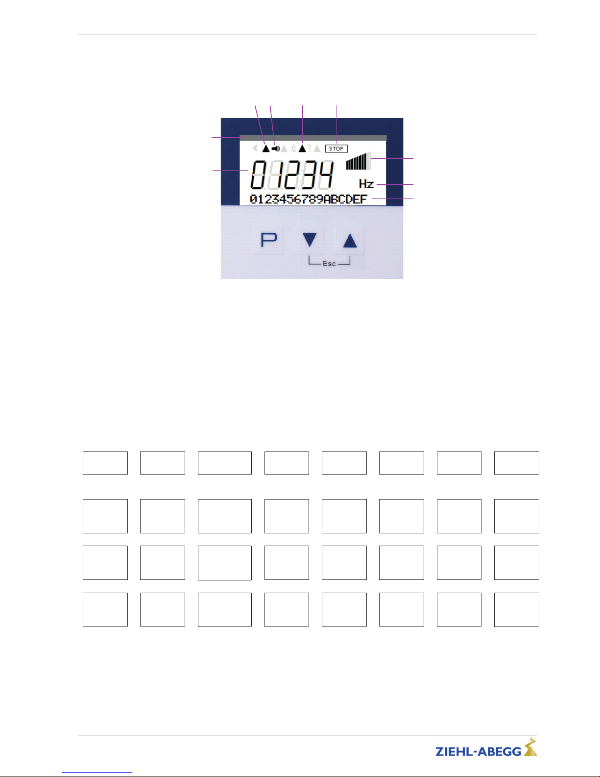
Display of icons depends on the software version and the add-on modules used
1. Numeric display 5 digit
2. Device name and software version
3. Current derating active
4. Alarm-Symbol (fault indication)
5. Temperature managment (power reduction active)
6. STOP-Symbol (enable)
7. Bargraph Fanlevel
8. Text line 3 figures (display unit, etc.)
9. Text line 16 figures (display text menu.)
P
Program key and open menu
Menu selection, reduce value
Menu selection, increase value
ESC-key combination, Escape = leave menu
▼
▲
▼ + ▲
6.2 Menu structure
Start
▼
▲
Info
▼
▲
Events
▼
▲
Setting
▼
▲
Controller
Setup
▼
▲
IO Setup
▼
▲
Motor
Setup
▼
▲
Diagnostic
P↓ ↑ ESC
P↓ ↑ ESC
P↓ ↑ ESC
P↓ ↑ ESC
P↓ ↑ ESC
P↓ ↑ ESC
P↓ ↑ ESC
P↓ ↑ ESC
OFF
PIN input
25.9 Hz
Frequency
19 1
50.0 Hz
Set Inter-
nal1
0
Control-
mode
1D
D1 Func-
tion
2.50 A
MotorRa-
tedCurr.
22.5 °C
IGBT
temp.
Motor fault
▲ ▼
▲ ▼
▲ ▼
▲ ▼
▲ ▼
▲ ▼
▲ ▼
▲ ▼
OFF
Reset
0.0 A
Motor cur-
rent
18 2
50.0 Hz
Setpoint2
75 %
Limit
OFF
D1 Invert-
ing
400 V
MotorRa-
tedVolt.
22.5 °C
Capacitor
Line Fault
▲ ▼
▲ ▼
▲ ▼
▲ ▼
▲ ▼
▲ ▼
▲ ▼
▲ ▼
D
Language
100 %
Modulation
17 3
50.0 Hz
Set Inter-
nal3
ON
LED Mode
2K
K1 Func-
tion
48.5 Hz
Edgefre-
quency
22.5 °C
MCU
Temp.
Motor fault
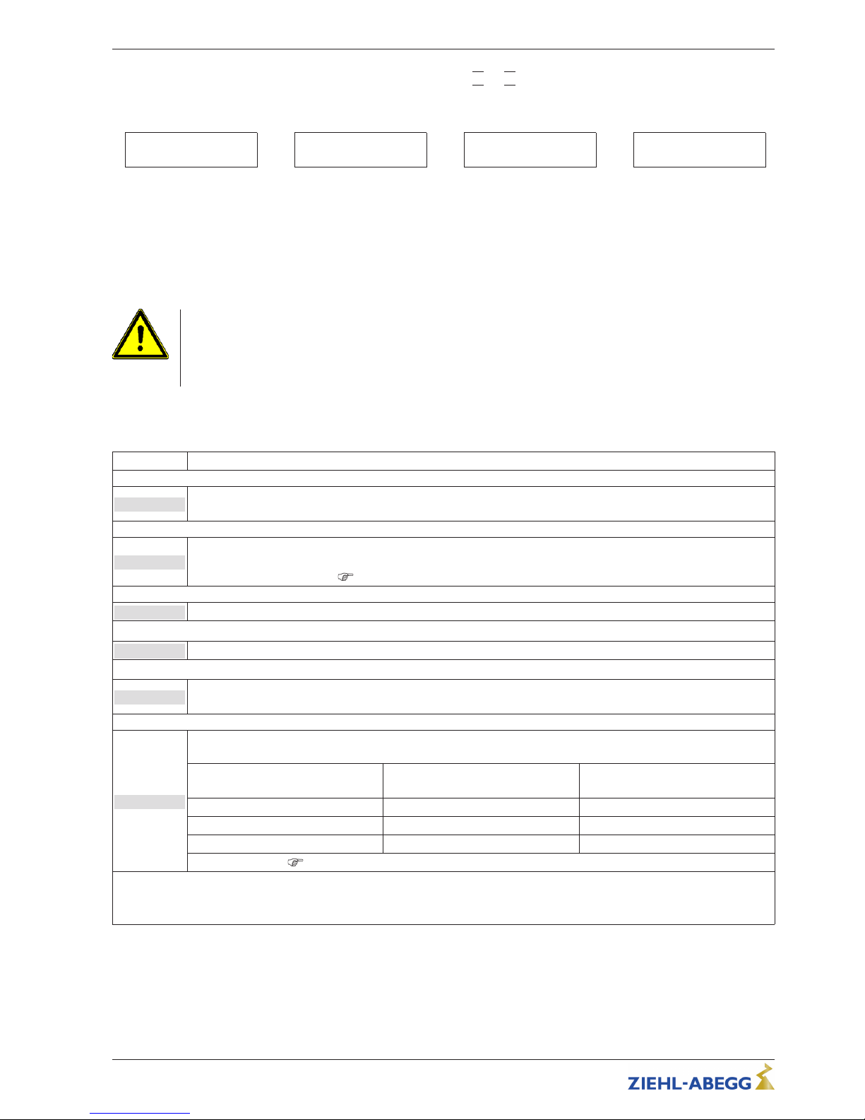
Selection of the menu group (e.g. Controller Setup) to the right through the ▼-key, to the left through
the ▲-key.
You can go to the menu items in the menu groups (e.g. control mode) by using the P key. Use the
arrow keys to move up and down within the menu group.
To make adjustments, press the P key after selecting the menu item. If the previously set value starts
to flash, it can be adjusted with the ▼ + ▲ keys and then saved with the P key. To exit the menu
without making any changes, use the “Esc” short-key, i.e., the originally set values remain.
Operating Instructions Fcontrol Basic – model series FSDM2.5..50AM Controls and Menu
L-BAL-E174-GB 1704 Index 005 Part.-No.
21/49
Page 22
Example: Programming “Controlmode” |0| to |1| in “Controller Setup”
1 2 3
4
5 6 7
0
Controlmode
P
« 0 »
Controlmode
▲
« 1 »
Controlmode
P
1
Controlmode
7 Start-up
7.1 Prerequisites for commissioning
Attention!
1. You must mount and connect the device in accordance with the operating instructions.
2. Double check that all connections are correct.
3. The mains voltage must match the information on the rating plate.
4. The rated current on the rating plate will not be exceeded.
5. Make sure that no persons or objects are in the hazardous area.
7.2 Procedure for commissioning
Sequence Setting
1
Check if Thermostats or Thermistors of the motor are connected to input “TB/TP In”.
If the motor protection function of the device is not neccesary the both terminals “TB / TP” have to be bridged.
2
Check if contact for enable is conected to “Digital In 1”.
If the device remote control is not required, the two terminals “D1 / 24V” must be bridged or alternatively the
function “Enable” deactivate
IO Setup.
3
Check connection and close housing carefully.
4
Turn on mains voltage.
5
If necessary, set the menu language in Menu group Start.
(Factory setting Englisch: “Language GB”)
6
The Motor Setup factory installed values are for variable voltage external rotor motors 400 V / 50 Hz. After
checking of the motor data the setting are to be adapted if necessary.
Motor rated voltage
(see Rating plate)
Setting
Edgefrequency
Setting
Max. Frequency
3 ~ 400 V, 50 Hz 48.5 Hz 50 Hz
3 ~ 400 V, 50/60 Hz 48.5 Hz 60 Hz
3 ~ 400 V, 60 Hz 57 Hz 60 Hz
Additional settings
Motor Setup.
Settings for U/f characteristic can only be made when no motor modulation is present!
" Switch off via a digital input for remote control (enable= OFF).
" Reduce speed setting signal or setting value to “0” with the display depending on the control mode.
Operating Instructions Fcontrol Basic – model series FSDM2.5..50AM Start-up
L-BAL-E174-GB 1704 Index 005 Part.-No.
22/49
Page 23
8 Programming
8.1 Menu group Setting
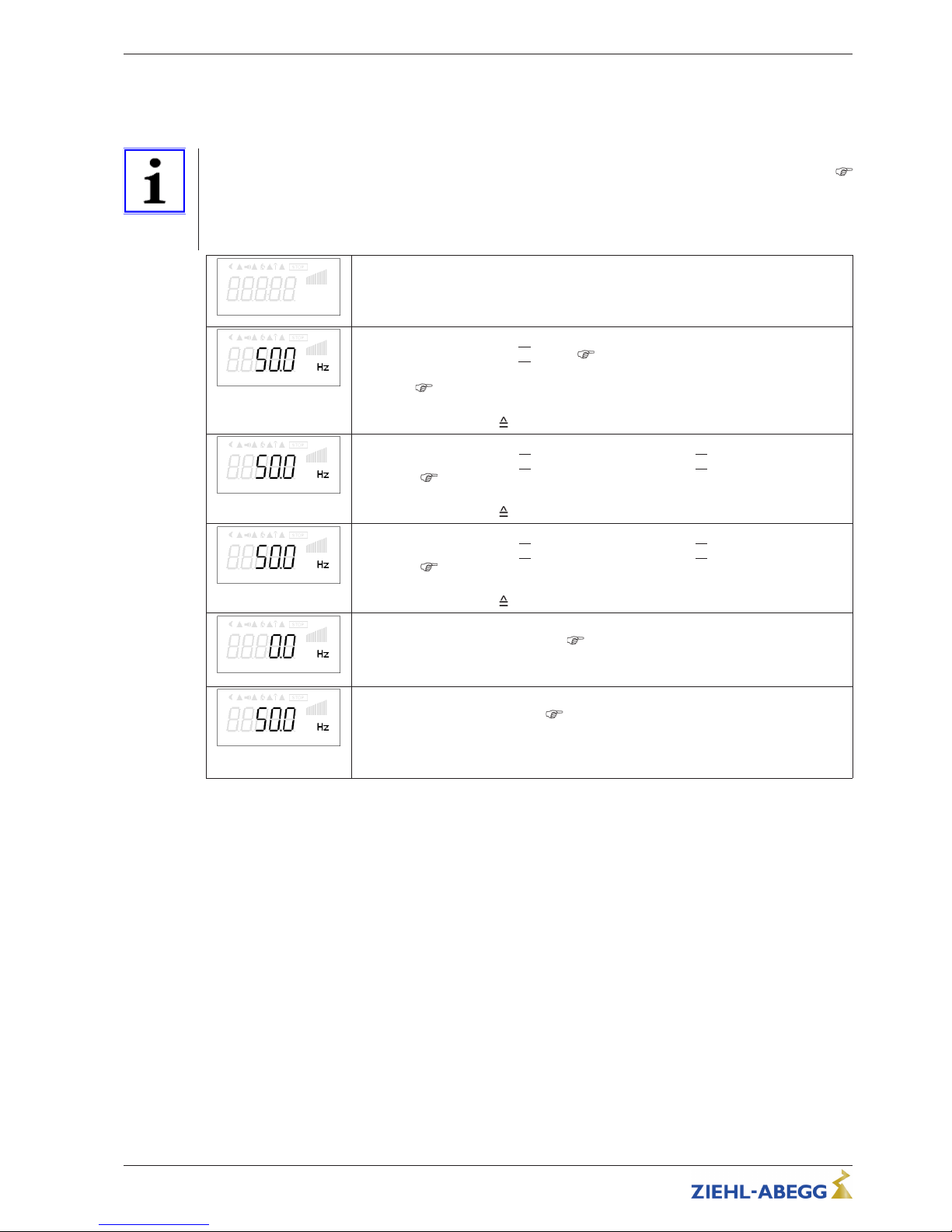
Information
•
Factory setting: Activation by external signal (0 - 10 V / PWM) at input “E1” (control mode = 0
Controller Setup). I.e. the following settings “Set Internal1”, “Set Internal2”, “Set Intern3” are not
active!
•
The following factory settings specifications are not binding, these values can differ depending on
the software version and customer-specific pre-setting.
Se tti ng
Setting
Set Inte rnal1
Set Internal1
Setting only in Controlmode
|4|
active ( Controller Setup).
Via the inputs “D1” / “E1” it is possible to switch to “Default Internal2” or “Default
Internal3” (
IO Setup).
Setting range manual speed setting: “Min. Speed” - “Max. Speed”
Factory setting: 50.0 Hz (
Setting “Max. Speed”)
Se tpo in t2
Setpoint2
Setting only in control mode
|6|
active only in control mode |4|, if activated via inputs
“D1” / “E1” (
Controller Setup / IO Setup).
Setting range manual speed setting: “Min. Speed” - “Max. Speed”
Factory setting: 50.0 Hz (
Setting “Max. Speed”)
Set Inte rnal3
Set Internal3
Setting only in control mode
|6|
active only in control mode |4|, if activated via inputs
“D1” / “E1” (
Controller Setup / IO Setup).
Setting range manual speed setting: “Min. Speed” - “Max. Speed”
Factory setting: 50.0 Hz (
Setting “Max. Speed”)
Mi n. S pe ed
Min. Speed (basic speed only when needed)
Setting range: 0... “Max. Frequency” (
Motor Setup).
Factory setting: 0.0 Hz
Active in every control mode, priority by “Max. speed”.
Ma x. S pe ed
Max. Speed (speed limitation only when needed)
Setting range: “Max. Frequency” (
Motor Setup)... “Min. Speed”
Factory setting: 50.0 Hz
Active in every control mode!
Settings by “Max. frequency” are possible but are not made!
Operating Instructions Fcontrol Basic – model series FSDM2.5..50AM Programming
L-BAL-E174-GB 1704 Index 005 Part.-No.
23/49
Page 24
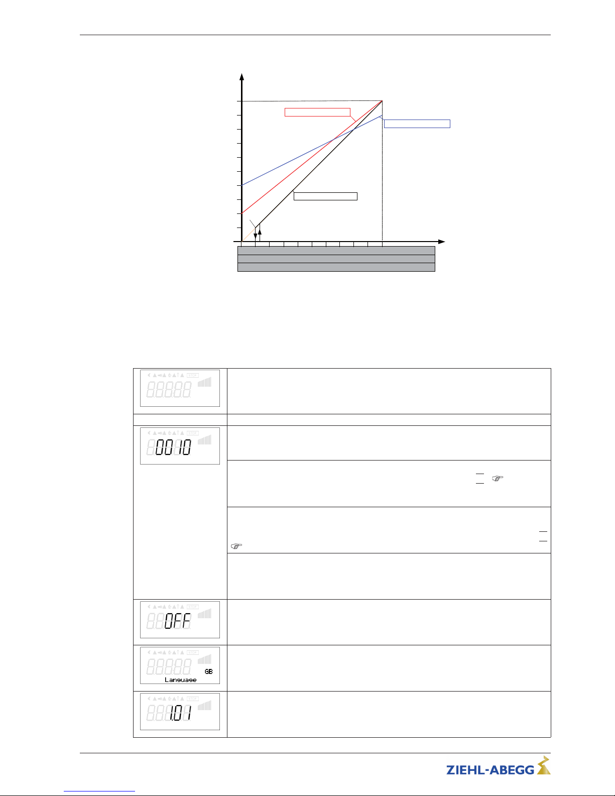
Diagram setting signal and output frequency
F
out
[Hz]
08.05.2012
v_fxdm_setsig_min_max.vsd
1 2
3
4 5
6
7 8
9
10
Analog In 1
40
35
30
25
20
15
10
5
2 4
6
8 10
12 14 16
18
20
0...10 V
0...20 mA
10 20
30
40 50
60 70 80
90
100
0...100 % PWM
0
0
0
45
50
n-min OFF n-max. = 50 Hz
n-min 20 Hz n-max. = 45 Hz
n-min 10 Hz n-max. = 50 Hz
F
off
= 5 Hz
F
on
= 6 Hz
Fout: Output frequency
Analog In: Speed setting signal
n-min: Min. Speed
n-max: Max. Speed
Foff: Shutdown Freq.
Fon: Switch on Freq.
8.2 Menu group Start
Sta rt
Start
PI N in pu t
PIN input
The service menu for the installation can be protected against unintentional changes
by a pin code. With further pin codes putting back to pre-setting is possible.
PIN 0010
Release of the service settings with programmed PIN-Accesslevel
|0|
( “Controller
Setup”).
Menu groups Service: “Controller Setup”, “IO Setup”, “Motor Setup”
PIN 1234
Opening “setting”.
Release of the menu group for the user “setting” with programmed PIN-Accesslevel
|0|
( “Controller Setup”).
PIN 9095
Load factory setting (exception, the menu language setting is retained).
Only the parameters which are released by the currently set PIN-Accesslevel are
loaded.
Res et
Reset
Complete re-start of the device
Language
Menu language by the factory set to English.
In this menu different national languages can be selected (GB = English, D = German
...).
Fi rmw ar e
Software version
Operating Instructions Fcontrol Basic – model series FSDM2.5..50AM Programming
L-BAL-E174-GB 1704 Index 005 Part.-No.
24/49
Page 25
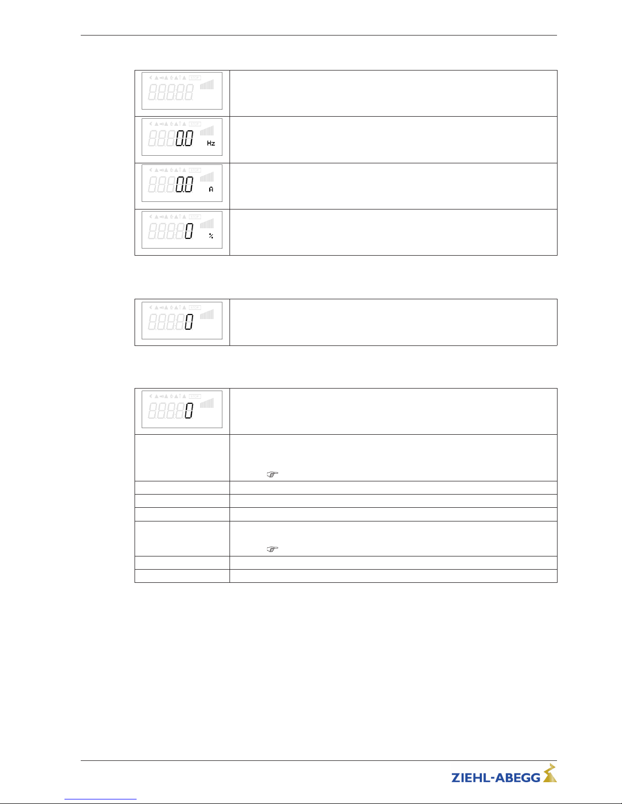
8.3 Menu group Info
Inf o
Info
Fr equ en cy
Inverter output frequency.
Mot or cu rr ent
Display of motor current (Metering precision approx. +/-10%)
Mod ul at io n
Device modulation
8.4 Controller Setup
Co ntr ol le r S et up
8.4.1 Controlmode
Co ntr ol mo de
Type of device modulation.
0
Factory setting
Control by external signal (0 - 10 V / PWM) at the input “E1”.
Switching to fixed speed “Default Internal2” or “Default Internal3” via digital input
possible (
IO Setup).
1
no function
2
no function
3
no function
4
constant speed “Set Internal1”.
Switching to fixed speed “Default Internal2” or “Default Internal3” via digital input
possible (
IO Setup).
5
Fixed speed “Default Internal2” (without switching possibility to other default).
6
Fixed speed “Default Internal3” (without switching possibility to other default).
Operating Instructions Fcontrol Basic – model series FSDM2.5..50AM Programming
L-BAL-E174-GB 1704 Index 005 Part.-No.
25/49
Page 26
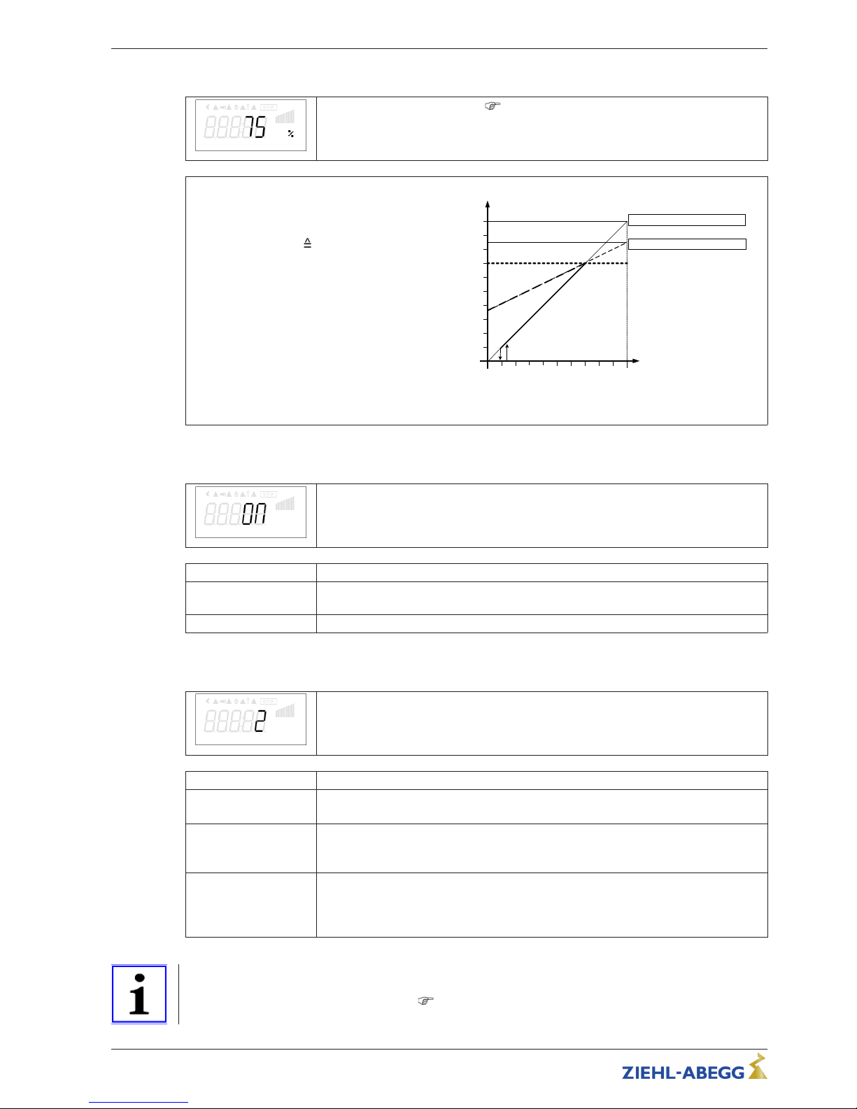
8.4.2 Limit
Lim it
After allocation of a digital input (
IO Setup) an adjustable limitation of the modulation
can be activated via a digital input.
“Limit value” = max. possible modulation (e.g.
speed reduction during night operation by
time switch).
Setting range: 0 - 100 %
Factory setting: 75 %
max. modulation, i.
e. no limit.
Limit (idealized principle diagram)
n [%]
50
100
Si [%]
Min.
L= 70% Min.= 0 % Max. = 100 %
50
L
L = 70% Min. = 35 % Max. = 85 %
07.10.2010
v_limit_101_rpm.vsd
0 100
n [%] Motor speed
L Limit
Si Speed setting signal
8.4.3 LED Mode
LE D Mo de
LED Mode
Only for versions with integrated status LED!
Setting
Function
ON
Status LED in ECblue active i.e. operating conditions are indicated by flash code
(factory setting).
OFF
Status LED not active, i.e. always OFF.
8.4.4 PIN-Accesslevel
PIN -A cc es sl ev el
PIN-Accesslevel
The PIN-Accesslevel determines for which setting ranges a PIN must be entered.
Setting
Function
2
Factory setting
All menu groups are visible, settings are possible without a PIN.
1
•
The menu group “Setting” is free, i.e. changes are possible without a PIN.
•
PIN 0010: for changes in the menu groups: “Controller Setup”, “IO Setup” and
“Motor Setup” (these menu groups are not visible without a PIN).
0
All settings are only possible after entering a PIN.
•
PIN 1234 for changes in the menu group: “Setting”
•
PIN 0010: for changes in the menu groups: “Controller Setup”, “IO Setup” and
“Motor Setup” (these menu groups are not visible without a PIN).
Information
Changes for the PIN protection which effect a reduced access right only become active after switching
off the device or executing the “Reset” (
Start menu group) function.
Operating Instructions Fcontrol Basic – model series FSDM2.5..50AM Programming
L-BAL-E174-GB 1704 Index 005 Part.-No.
26/49
Page 27
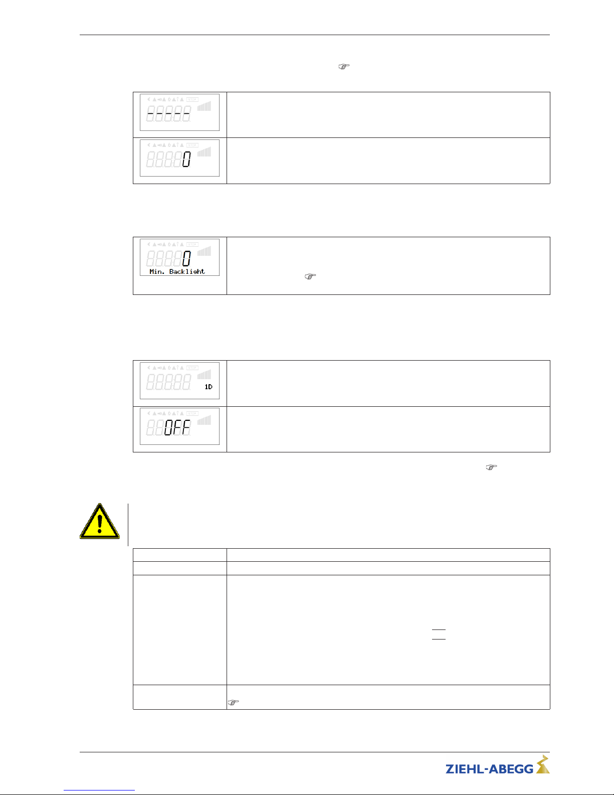
8.4.5 Wireless Communication
Only with add-on module AM-MODBUS- W active
oprating instructions (operation with add-on
module not possible at the moment).
Ne two rk ke y
Network key
RF c ha nn el
RF channel
8.4.6 Min. Backlight
Setting options depending on the version of the software available!
Min. Backlight
Backlight setting for the display, which is activated after approx. 1 minute without
pressing a key.
Setting range: 0 - 10 min. - max. lighting intensity
Factory setting: 0
8.5 Menu group IO Setup
8.5.1 Digital inputs “D1” (“E1” *)
D1 F un ct io n
Different functions can be assigned to the digital inputs “D1” and “E1”*.
Activation via floating contacts (a low voltage of approx. 24 V DC is connected).
“D1” is programmed for the “Enable” function at the factory.
D1 I nv er ti ng
For inverting switch to “ON”.
The input inversion is set at the factory to “OFF” (when a function is programming).
* If the analogue input “E1” is not required for specifying the fan speed, this can be used as a digital input (
E1 function).
The same functions can be assigned for “E1” as for “D1”.
Attention!
Never apply line voltage to the digital input!
Function Description
OFF No function
1D Enable ON / OFF (factory setting)
Remote ON/OFF (electronic disconnection) and Reset after a motor malfunction via
floating contact. The power section is electronically disconnected. Operation of the
device is still possible after pressing the “Esc” hotkey combination in switched-off
condition. Signal- in and outputs remain active.
A programmed alarm relay (factory set “K1 function” =
|2K|
) does not report the
switch-off.
Attention!
No disconnection (no potential isolation in accordance with VBG4 §6) in remote control
of the device!
3D Limit ON / OFF
Controller Setup / Limit
Operating Instructions Fcontrol Basic – model series FSDM2.5..50AM Programming
L-BAL-E174-GB 1704 Index 005 Part.-No.
27/49
Page 28
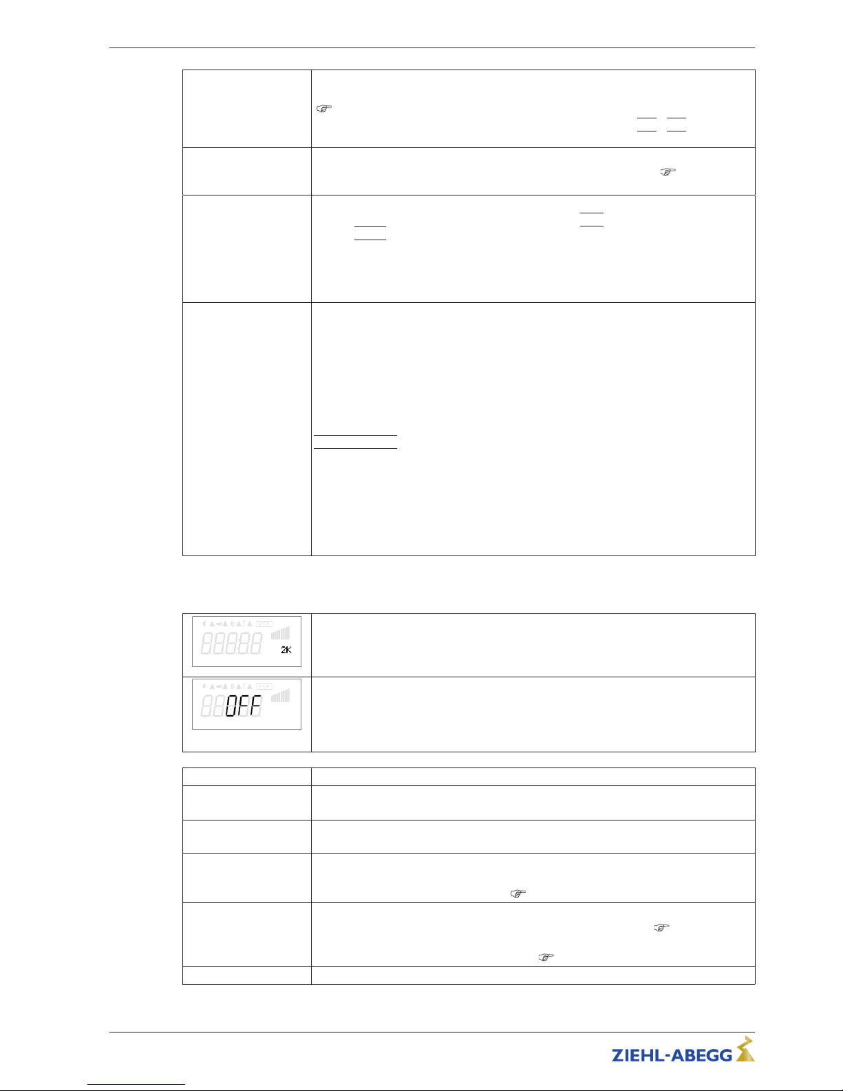
5D Setpoint2
Fixed speed “Default Internal2” active. Function with selected “control mode”: 0, 1, 2 , 3
(
“Controller Setup”).
With simultaneous activation of “Default Internal3” with function
|6D|, |5D|
has prior-
ity).
6D Set Internal3
Constant speed “Set Internal3”, also with selected “control mode”: 0 (
“Controller
Setup”).
13D Switch over direction of rotation
Switch over between direction of rotation “RIGHT” =
|CW|
and direction of rotation
“LEFT”
|
CCW|.
When“switching”over via a digital input, the device works with the opposite direction of
rotation than the one set in Motor Setup.
If the rotary direction is reversed with an available modulation, it is initially reduced to
“0” (disconnected) and subsequently increased back to the default value.
15D Smoke extraction: Switch off temperature management, operation at max. speed
To make the ECblue as durable as possible, the devices have active temperature
management. The modulation is reduced when internal temperature limits are exceeded.
In venting systems in which the fan must run at max. speed in the event of a fire, the
temperature management can be switched off by a digital input. At the same time, the
fan is operated independently of the speed default for regular operation at maximum
speed.
The function is activated at the digital input with the contact open (at factory setting
|
D1/E1 Inverting| = OFF) so that the maximum speed of the fan is also possible with
the line to the digital input interrupted in case of fire.
Attention!
The device and its internal components are no longer protected against overtemperature when this function is activated (this affects the life installation instructions ECblue).
The motor protection function by connected thermal protector is no longer effective!
8.5.2 Relay outputs “K1”
K1 F un ct io n
Various functions can be allocated to the relay outputs “K1”.
This is preset at the factory for fault indication.
K1 I nv er ti ng
For switching inversion to “ON” (switching behaviour dependent on assigned function).
The relays can only pull up basically when the voltage supply of the electronics is
working. Three-phase current devices must have at least 2 line phases!
The relay inversion “K1” is set at the factory to “OFF” (when a function is program-
ming).
Function Description
OFF No function
Relays remain always de-energized.
1K Operating indication
Operation without fault, reports enable “OFF”.
2K Fault indication (factory setting)
Pulled up in operation without fault, with release “OFF” not dropped out.
Drops out at: line fault, motor fault, etc.
Events / Fault indications
4K Limits
Alarm when the speed exceeds the value set under “Set Internal3” (
menu group
“Setting”) (output power > 0 %).
The function is active in every control mode (
menu group: “Controller Setup”).
17K no function
Operating Instructions Fcontrol Basic – model series FSDM2.5..50AM Programming
L-BAL-E174-GB 1704 Index 005 Part.-No.
28/49
Page 29
10.11.2008
v_relais_k1_13_14.vsd
K1
1413
K1
1 = energized, terminals 13 - 14 bridged
0 = de-energized 13-14 not bridged
Function Status Controller K1
1 = energized
0 = de-energized
Inverting
OFF ON
1K Operation without fault, line supply okay 1 0
2K Fault with indication by relay 0 1
4K Exceed Frequency / Speed > setting “Set Internal3” 1 0
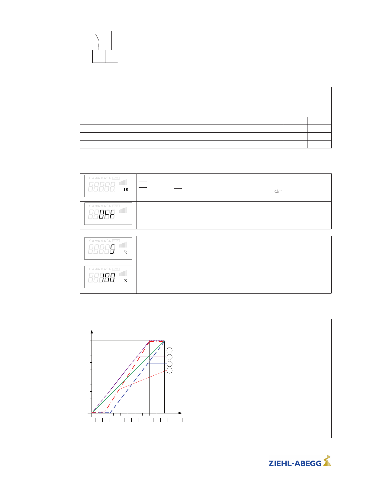
8.5.3 Input “E1”
E1 F un ct io n
E1 Function
|1E|
(factory setting) = speed setting by external signal (0 - 10 V / PWM).
For settings via
|1E|
“E1” operates like “D1” as a digital input ( digital inputs /
function).
E1 I nv er ti ng
E1 Inverting
Factory setting inverting to “OFF”.
For control with inverted setting signal switch to “ON” (setting signal: 10 - 0 V).
E1 M in .
E1 Min.
Value of the input signal at which the controller starts at minimum modulation.
Setting range: 0 - 100 %
Factory setting: 5 %
E1 m ax
E1 max
Value of the input signal at which the maximum modulation of the controller is reached.
Setting range: 0 - 100 %
Factory setting: 100 %
Example for signal adaption
Idealized principle diagrams for setting: “Min. Speed” = 0.0 Hz and “Max. Speed” = 50.0 Hz
F
out
[Hz]
Si E
0 1 2 3 4 5 6 7 8 9 10 0 – 10 V
15.02.2012
v_e1_adjust_i_basic.vsd
1
E1 min. = 0 %, E1 max. = 100 %
50
2
E1 min. = 25 %, E1 max. = 100 %
40
30
20
10
3
E1 min. = 20 %, E1 max. = 80 %
E1 min. = 0 %, E1 max. = 80 %
4
Fout Output frequency
Si E Speed setting signal
Example: “E1 min.” = 20 %
The controller begins only at approx. 20%
higher signal with minimal modulation.
Example: “E1 max.” = 80 %
The modulation rises linear to 100% modulation with 80% setting signal.
Operating Instructions Fcontrol Basic – model series FSDM2.5..50AM Programming
L-BAL-E174-GB 1704 Index 005 Part.-No.
29/49
Page 30
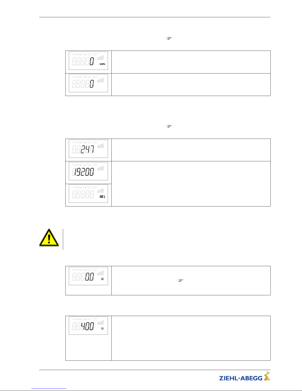
8.5.4 MODBUS communication watchdog
The MODBUS communication watchdog defines the behaviour in case of a communication fault.
Only with add-on module AM-MODBUS- W active
oprating instructions (operation with add-on
module not possible at the moment).
Wat ch do g T im e
Watchdog Time
Wat ch do g M od e
Watchdog Mode
8.5.5 Networking via MODBUS
It is possible to network several devices with each other. The device uses the MODBUS-RTU as the
protocol for the RS-485 interface.
Only with add-on module AM-MODBUS- W active
oprating instructions (operation with add-on
module not possible at the moment).
Bu s Ad dr es s
Bus Address
Com . B au dr at e
Com. Baudrate
Co m. M od e
8.6 Menu group “Motor Setup”
Attention!
Settings for U/f characteristic may only be made when no motor modulation is present!
8.6.1 Setting motor rated current
Mot or Ra te dC ur r.
MotorRatedCurr.
Possible setting for the motor rated current.
The setting for the “DC brake level” (
setting brake behaviour) refers to this setting.
Setting range: 0.0...device rated current / A
Factory setting: device rated current
8.6.2 Setting motor rated voltage
Mot or Ra te dV ol t.
MotorRatedVolt.
When commissioning, you must set the motor to the rated voltage stated on the rating
plate.
An adaptation can be made if the motor rated-voltage as the applied mains voltage is
lower (e.g. 3 ~ 230 V motor on 3 ~ 400 V mains).
Verify the output voltage using suitable measuring instruments.
Setting range: 0...500 V
Factory setting: 400 V
Operating Instructions Fcontrol Basic – model series FSDM2.5..50AM Programming
L-BAL-E174-GB 1704 Index 005 Part.-No.
30/49
Page 31
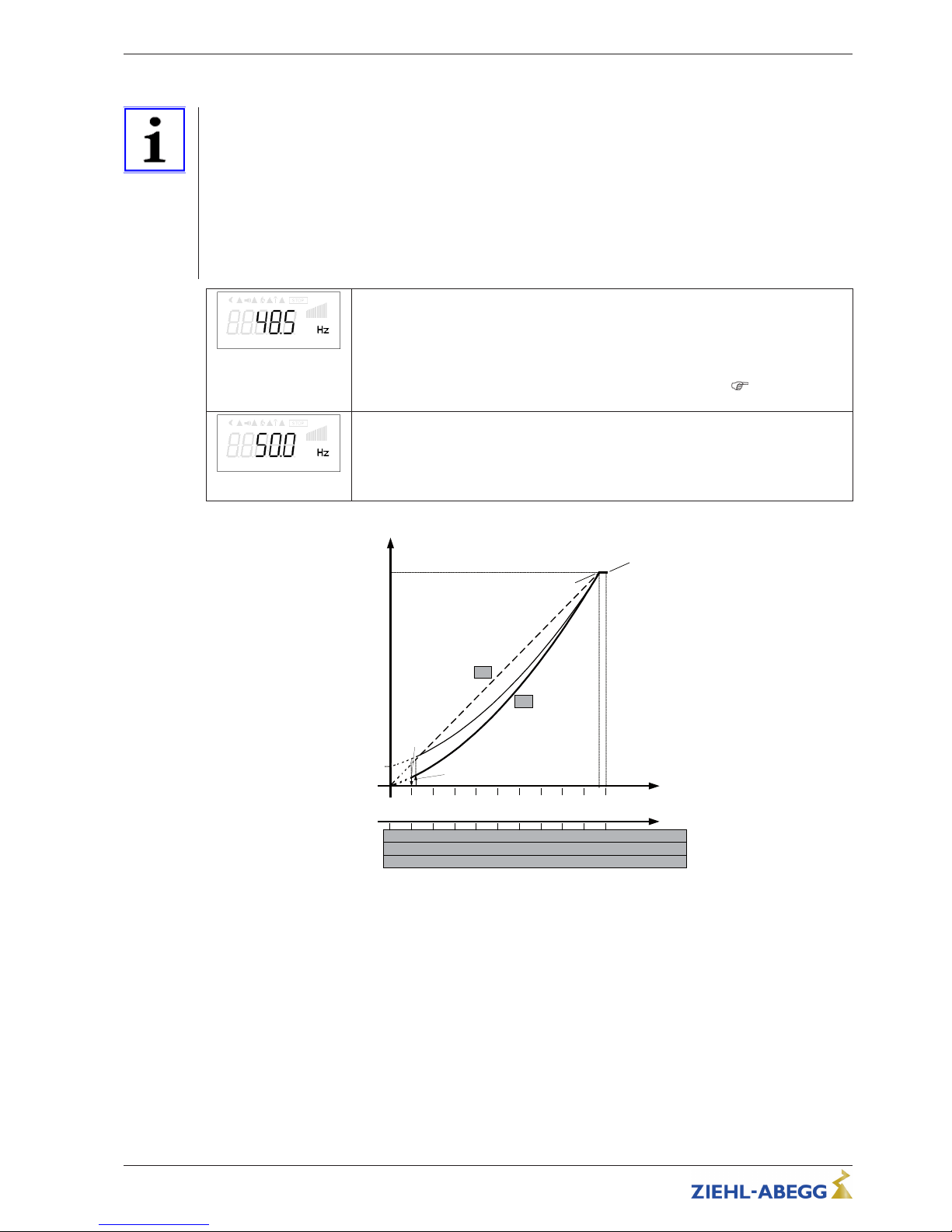
8.6.3 Adjustment of the U/f curve
Information
The device comes supplied with a preprogrammed square characteristic curve for the operation of
fans.
In the case of voltage-controllable motors and square load torque-moments (e.g. fans and pump
operation), an optimal speed control is generally achieved through this.
In systems in which high dynamics are required, switchover to a linear characteristic must take place.
Generally speaking, if the load characteristic is not known as a definite value, the linear characteristic
should be set. In the case of linear characteristic curves, the motor achieves full torque throughout the
entire speed range. For this, a thermal overload of the motor must be prevented through suitable
measures (complete motor protection through using thermocontact or PTC thermistor-monitoring).
Ed gef re qu en cy
Edgefrequency
The maximum output voltage is attained during break edge frequency.
Adjustment range: 1.0 - 120.0 Hz
Factory setting: 48.5 Hz
In the case of special settings with “Edge frequency” > “Max. Frequency”, due to higher
power losses it is possible that automatic power reduction occurs (
Messages and
trouble shooting “Temp. Manager”).
Ma x. F re qu en cy
Max. Frequency
Above the Edgefrequency, the frequency is merely increased up to the Maximum
frequency.
Adjustment range: 1.0 - 120 Hz
Factory setting: 50.0 Hz
F
out
[Hz]
F
max
= 50 Hz
F
off
26.07.2012
v_u_f_dia_fcontr_d.vsd
1 2
3
4 5
6 7 8
9
10
Analog In 1
0
45
50
403530
25
2015
10
5
2 4
6
8 10
12 14 16
18
20
0...10 V
0...20 mA
10 20
30
40 50
60 70 80
90
100
0...100 % PWM
F
edge
= 48.5 Hz
U
out
100 %
F
on
0.5
1
5
Q
L
U
start
= 10 %
U
start
= 0 %
Uout Output voltage
Fout: Output frequency
Analog In Speed setting signal (0 - 10 V, 0...20 mA, 0...100 % PWM)
Ustart Startvoltage
Foff Shutdown Freq.
Fon: Switch on Freq.
Fedge Edgefrequency
Fmax Max. Frequency
L linear
Q Square (factory setting)
Due to technical reasons the output voltage amounts to approx. max. 95 % of the applied mains
voltage.
In order to still be able to achieve the maximum airflow of the connected fans, an increase of the
maximum frequency is possible for our motors. For this, a current increase must be included in the
calculation. It is necessary to optimize monitoring of motor current, output voltage, and speed using
suitable measuring instruments.
Operating Instructions Fcontrol Basic – model series FSDM2.5..50AM Programming
L-BAL-E174-GB 1704 Index 005 Part.-No.
31/49
Page 32
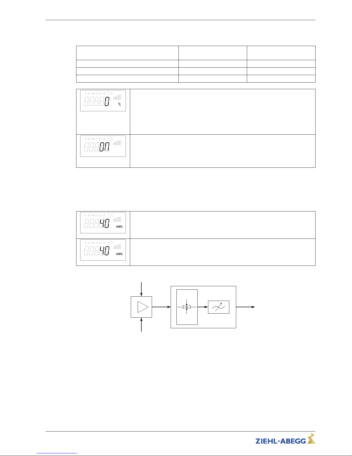
The factory set values are for voltage controllable external rotor motors with 400 V / 50 Hz.
After verification of the motor specifications, adjustments are to be adapted, if applicable.
Motor rated voltage
(see Rating plate)
Setting
“Edgefrequency”
Setting
“Max. Frequency”
3 ~ 400 V, 50 Hz 48.5 Hz 50 Hz
3 ~ 400 V, 50/60 Hz 48.5 Hz 60 Hz
3 ~ 400 V, 60 Hz 57 Hz 60 Hz
St art vo lt ag e
Startvoltage
The start voltage is used to apply enough torque to the motors to insure they will run at
low speed.
Attention! In order to prevent over current and unnecessarily high thermal load of the
motor, do not select to high a setting.
Adjustment range: 0 - 15 % (percentage of the maximum output voltage)
Factory setting: 0 %
VF q ua dr at ic
VF quadratic
U/f curve linear or square
Factory preprogrammed square characteristic curve “UF square” = “ON” for the
operation of voltage controllable fans.
For operation with linear curve “UF quadratic” = “OFF ”
8.6.4 Setting for Rampup time and Rampdown time
By separate menus for Rampup time and Rampdown time an adjustment is possible to individual
system conditions.
This function is switched behind the actual controller function.
Ra mpu p t im e
Rampup time
Time setting in which the automatic controller output from 0 % to 100 % rises.
Setting range: 0...250 sec.
Factory setting: 10 / 20 / 30 / 40 sec. (depending on device type)
Ram pd ow n t im e
Rampdown time
Time setting in which the automatic controller output from 100 % to 0 % reduces.
Setting range: 0...250 sec.
Factory setting: 10 / 20 / 30 / 40 sec. (depending on device type)
0 .. 100 %
3
4
1
2
09.05.2007
v_hochlaufzeit_ruecklaufzeit.vsd
1 external Signal
2 Setting
3 Rampup time
4 Rampdown time
Operating Instructions Fcontrol Basic – model series FSDM2.5..50AM Programming
L-BAL-E174-GB 1704 Index 005 Part.-No.
32/49
Page 33
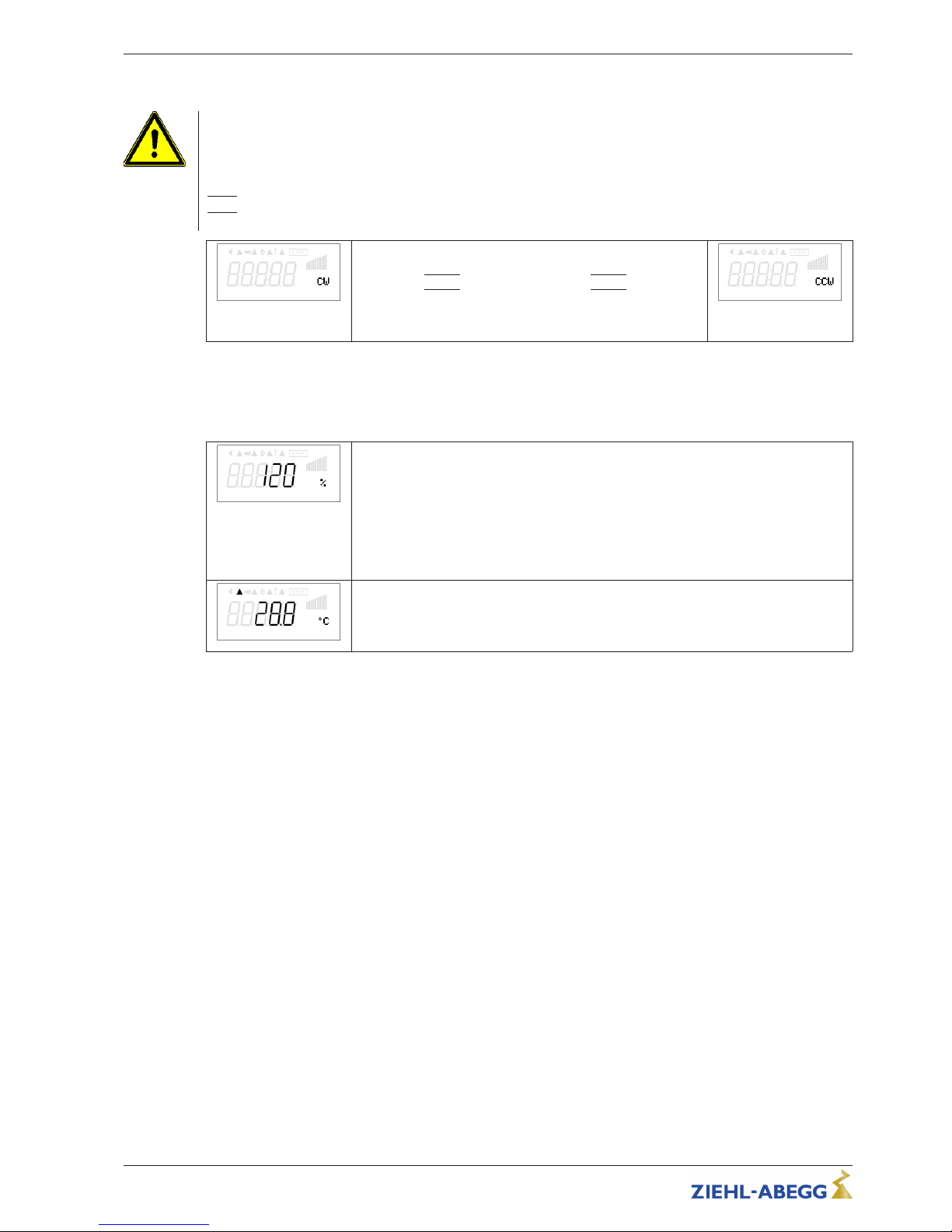
8.6.5 Setting Rolling direct.
Attention!
It is essential to check the direction of rotation of the fan during the initial commissioning. To do this,
note the direction of the arrow on the fan housing. We will not be responsible under any circumstances
for warrantee for damage caused because the direction of rotation is wrong!
When connected in accordance with the connection diagram, the standard rotary direction “RIGHT” =
|CW|
results under factory settings. A change of direction is feasible by exchanging the phase
sequence in the motor connection or through reprogramming.
Ro tat . D ir ec ti on
By selection of the parameter “Direction of rotation” and
following pressing the P key, the direction of rotation can
changed to
|
CCW| for anti-“clockwise” = |CCW| direction of
rotation.
Pressing the P key causes the value that has been set to be
accepted.
Ro tat . D ir ec ti on
If the rotary direction is reversed with an available modulation, it is initially reduced to “0” (disconnected) and subsequently increased back to the default value.
8.6.6 Setting Current limit
Cur re nt li mit
As an additional safety function the device has a current limit, this can be adapted if
necessary.
The setting refers to the motor rated current of the device (100 % = setting: MotorRatedCurr.).
On exceeding the percentage value set here, the modulation is reduced until the set
current is set again. This prevents overloading of the motor.
Setting range: 100...130 %
Factory setting: 120 %
E1 A ct ua l
Active current limit is signaled by a bright triangle in the display
Operating Instructions Fcontrol Basic – model series FSDM2.5..50AM Programming
L-BAL-E174-GB 1704 Index 005 Part.-No.
33/49
Page 34
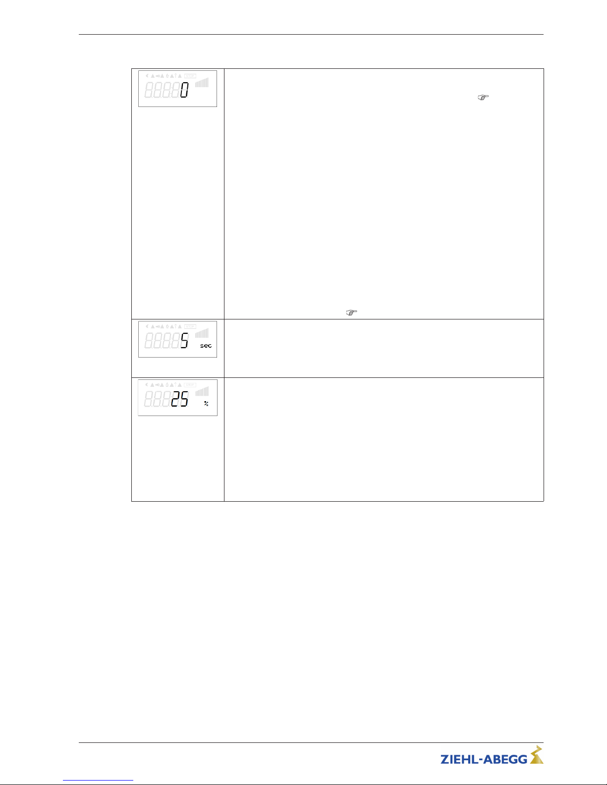
8.6.7 Setting brake function
DC b ra ke mod e
DC brake mode
Setting function of DC-brake for frequency inverters.
For units that come with a factory engaged DC brake mode (if extant,
DC brake
mode setting), simultaneously activating the “DC brake mode ” only makes sense in
exceptional cases.
0 = no brake function (factory setting).
1 = brakes before start (before modulation is returnd)
If, under certain circumstances, the modulation switches back on while the motor is still
rotating fast, this can result in a re-supply of the inverter’s “overcurrent disconnection”.
The brake function can be activated to prevent this. This is then always active for an
adjustable period before triggering starts. I.e., the brake function is always initiated
before modulation after has it returned to “0”. The suitable adjustments depend on the
centrifugal force of the motor and the conditions in the installation.
2 = Special function, brakes before stop (as soon as modulation “0”).
The motor does not run out up to stop. The motor is braked actively, as soon as no
modulation is present (Setpoint = “0” or Enable = “OFF”) .
Test required. The “min. speed” adjustment must be set to “0”.
Attention! With the frequently one behind the other following DC bracings it can come
to strong heating up of the motor.
To prevent any overheating, motor protection in the form of a temperature limiter
installed in the motor is required (
motor protection).
DC b ra ke tim e
DC brake time
Maximal length of DC-brake for frequency inverters.
If the braking is activated, the d.c. brake torque is active for this time.
Setting range: 0...250 sec.
factory setting: 5 / 10 sec. (depending on device type)
DC b ra ke lev el
DC brake level
Direct-current level, generated for braking. The higher this value, the greater the
braking effect.
The setting “DC brake level” refers in % to the value set in “MotorRated Curr.”.
Setting range: 25, 50, 75, 100 %
Factory setting: 25 %
The setting is dependent on the size of the fan/motor. Attention! Too high values can
lead to a considerable braking effect.
Same“setting”affects also the function Motorheating.
Operating Instructions Fcontrol Basic – model series FSDM2.5..50AM Programming
L-BAL-E174-GB 1704 Index 005 Part.-No.
34/49
Page 35
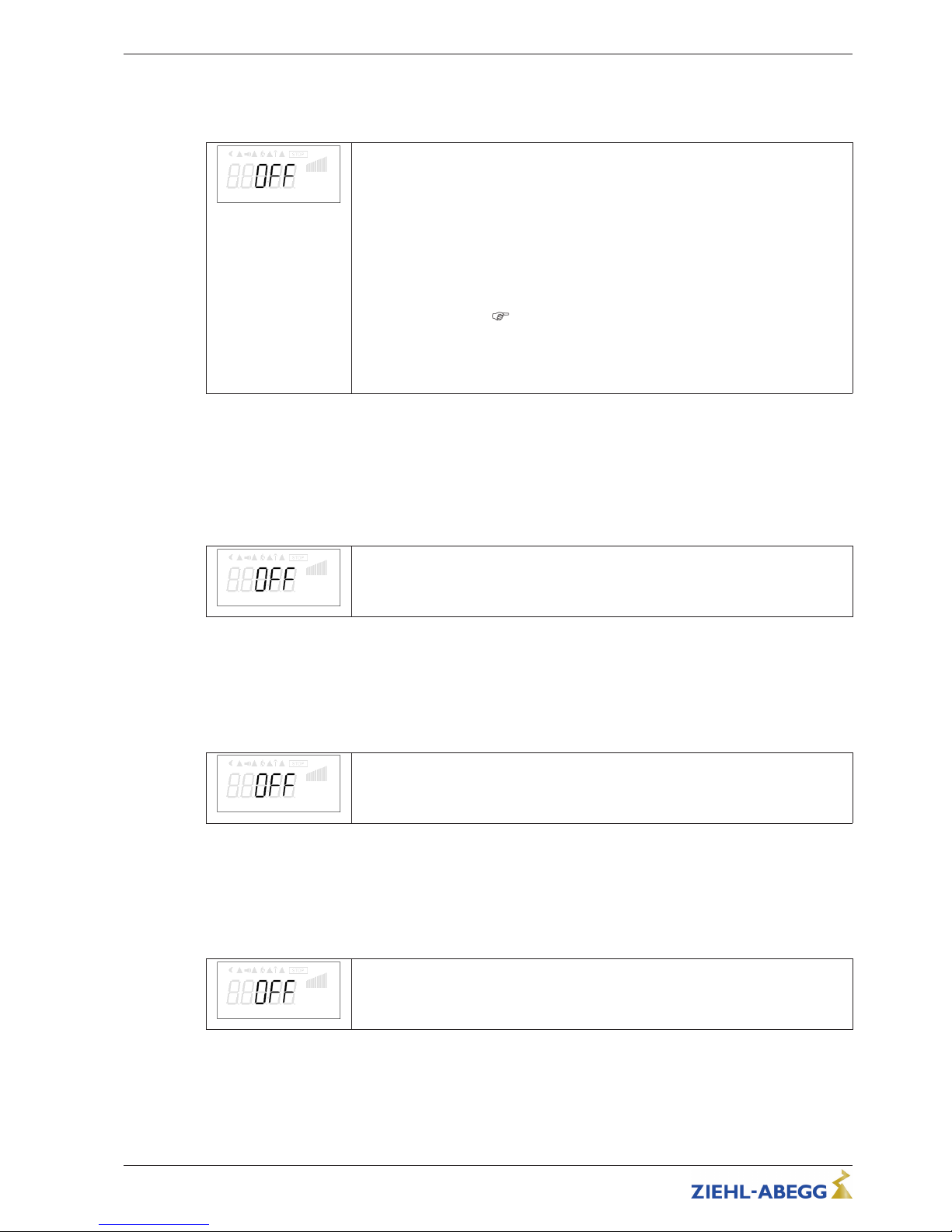
8.6.8 Motorheating
In order to avoid a sticking or a freezing of standing fans in cold environment, the “motor heating
system” can be switched on.
Mo tor he at in g
The motor heating function corresponds to the braking function in which a direct current
puts the motor into standstill. The height of the “brake level” is set in “Motor Setup”.
A current is impressed here, which does not permit any rotation of the fans. The value
required to prevent any freezing depends on the ambient conditions and the connected
motor’s technical data.
The setting effected is to be checked under real conditions. The higher the setting, the
greater the heating output generated in the motor (heat dissipation). The motor heating
or stationary heating can only become active, where there is no given modulation as a
result of regulation.
To prevent any overheating, motor protection in the form of thermal protection installed
in the motor is required (
motor protection). The heating function is switched off
when the motor protection function of the regulating unit responds.
OFF = motor heating switched off (at the factory)
ON = The motor heating becomes active automatically when there is no device
modulation.
8.6.9 Overload detection
Setting options depending on the version of the software available!
Apart from monitoring the temperature monitors installed in the motor, overload detection is a further
way of protecting the motor against overload.
With overload detection activated (I
2
t) there is an automatic reduction in the motor current if the set
motor rated current (see “MotorRatedCurr.”) is exceeded for a certain period.
Ov erl oa d d et ec t.
Overload detect.
OFF = overload detection switched off (at the factory)
ON = overload detection switched on
8.6.10 Ripple compensation
Setting options depending on the version of the software available!
The intermediate circuit voltage ripple can lead to output voltage fluctuations which may cause sounds
from the motor.
The ripple compensation can be activated to help reduce these sounds if necessary.
Ri ppl e c om pe ns ati on
Ripple compensation
OFF = ripple compensation switched off (at the factory)
ON = ripple compensation switched on
8.6.11 Rampdown limitation
Setting options depending on the version of the software available!
In case the rampdown time is set too low, the motor regeneration can lead to an overvoltage switchoff.
The rampdown limitation can be activated to help prevent this if necessary.
Ra mpd ow n l im it .
Rampdown limit.
OFF = rampdown limitation switched off (at the factory)
ON = rampdown limitation switched on
Operating Instructions Fcontrol Basic – model series FSDM2.5..50AM Programming
L-BAL-E174-GB 1704 Index 005 Part.-No.
35/49
Page 36
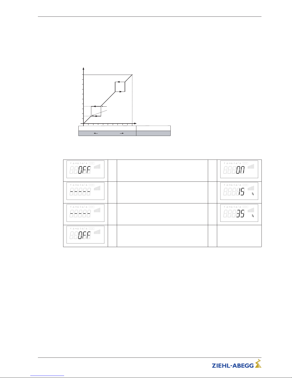
8.6.12 Suppression of speeds
Suppression of up to three speed ranges.
Under certain circumstances, it is possible to prevent disturbing noises that can arise at certain
speeds due to resonances.
Example for suppression of 2 ranges (Idealized principle diagram)
A
D
P
50 %
50 %
R
0 %
I
S
100 %
I
35 % max
15 % min
09.05.2007
v_ausblendung_prz.vsd
100 %
1
2
A Modulation
S Setpoint
R Pband
D Speed controller: setting signal
P P-controller: control deviation
Setting depending on device type
in: %, Hz, rpm
Su ppr es si on 1
→ Factory setting no suppression active = “OFF” →
Su ppr es si on 1
Ra nge 1 m in .
→ Setting for “Range1 min.”
Setting range: “Shutdown Freq.” - “Range 1 max.”
→
Ra nge 1 m in .
Ra nge 1 m ax .
→ Setting for “Range1 max.”
Setting range: “Range 1 max.” - “Max. Frequency”
→
Ra nge 1 m ax .
Su ppr es si on 2
→ Identical procedures for Suppression2 and Sup-
pression3, as far as desired
→ etc.
Operating Instructions Fcontrol Basic – model series FSDM2.5..50AM Programming
L-BAL-E174-GB 1704 Index 005 Part.-No.
36/49
Page 37
9 Parameter
9.1 Menu overview
Parameter Factory setting * User Setting Information
Start
PIN input OFF
Reset OFF
Language GB
Firmware 1.07
Info
Frequency 0.0 Hz
Motor current 0.0 A
Modulation 0 %
Events
Setting
Set Internal1 50.0 Hz
Setpoint2 50.0 Hz
Set Internal3 50.0 Hz
Min. Speed 0.0 Hz
Max. Speed 50.0 Hz
Controller Setup
Controlmode 0
Limit 75 %
LED Mode ON
PIN-Accesslevel 2
Network key - - - - -
Min. Backlight 0
RF channel
IO Setup
D1 Function 1D
D1 Inverting OFF
K1 Function 2K
K1 Inverting OFF
E1 Function 1E
E1 Inverting OFF
E1 min. 5 %
E1 max 100 %
Watchdog Time 0 sec
Watchdog Mode 0
Bus Address 247
Com. Baudrate 19200
Com. Mode 8E1
Operating Instructions Fcontrol Basic – model series FSDM2.5..50AM Parameter
L-BAL-E174-GB 1704 Index 005 Part.-No.
37/49
Page 38
Parameter Factory setting * User Setting Information
Motor Setup
MotorRatedCurr.
2.50 A
MotorRatedVolt.
400 V
Edgefrequency
48.5 Hz
Max. Frequency
50.0 Hz
Startvoltage
0 %
VF quadratic
ON
Rampup time
20 sec
Rampdown time
20 sec
Rotat. Direction
CW
Current limit
120 %
DC brake mode
0
DC brake time
10 sec
DC brake level
25 %
Motorheating
OFF
Overload detect.
OFF
Ripple compensation
OFF
Rampdown limit.
OFF
Suppression1
OFF
Range1 min.
10.0 Hz
Range1 max.
15.0 Hz
Suppression2
OFF
Range2 min.
20.0 Hz
Range2 max.
25.0 Hz
Suppression3
OFF
Range3 min.
30.0 Hz
Range3 max.
35.0 Hz
Diagnostic
IGBT temp. 32.0 °C
Capacitor 32.0 °C
MCU Temp. 32.0 °C
Output filter 27.3
E1 Input 0 %
DC-Voltage 565 V
Line voltage 330 V
Stateflags 1280
Faultflags 0
PIN-Accesslevel 2
* Specifications not binding, these values can differe depending on the software version and customer-specific pre-setting.
Operating Instructions Fcontrol Basic – model series FSDM2.5..50AM Parameter
L-BAL-E174-GB 1704 Index 005 Part.-No.
38/49
Page 39
10 Diagnostics menu
The diagnostics menu supplies information about the momentary operating condition of the device.
Diagnostic
32.0 °C
IGBT temp.
Display of the internal temperature of the power semiconductor.
32.0 °C
Capacitor
Display of electronics internal temperature.
32.0 °C
MCU Temp.
Display of the internal temperature of the microcontroller.
32.0 °C
Output filter
Only in version with integrated sine filter.
0 %
E1 Input
Signal height at analog input1“E1”.
565 V
DC-Voltage
The intermediate circuit voltage without load is the peak value of the input voltage.
In a three-phase supply network with 400 V, an intermediate circuit voltage of ca. 565 V
results. This voltage sinks slightly under load.
330 V
Line voltage
Line voltage peak value.
0
Stateflags
Not active in devices with integrated display.
0
Faultflags
Not active in devices with integrated display.
2
PIN-Accesslevel
Momentarily adjusted PIN-Accesslevel (
Controller Setup).
Operating Instructions Fcontrol Basic – model series FSDM2.5..50AM Diagnostics menu
L-BAL-E174-GB 1704 Index 005 Part.-No.
39/49
Page 40
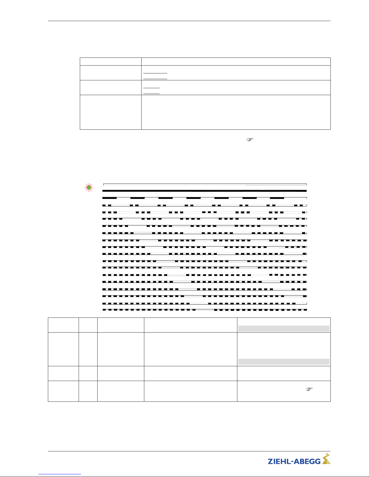
11 Events / Fault signals
11.1 Display and query of events and malfunctions
Events Menu group Events
The event memory is read out after pressing the P key.
|
Read »»»
|
0
Empty
Beispiel: keine vorliegenden Störungen
|
Empty| = no entry = no event in the memory
19 1
Example line fault
Position 1 = latest event
The last 10 (1 - 10) events are saved. The desired position can be selected with the
▼+ ▲ keys.
19 = number of all previous faults
Line Fault
An error message appears alternately with the actual value display (
Diagnostic faults).
11.2 Messages: Fcontrol / Icontrol Basic
A momentary pending alarm or error message appears alternately with the standard display.
Operating conditions are indicated by the status LED with flashing code.
internal State LED
10.01.2014
v_flash_explain_1_17.vsd
ON
OFF
1 x
16 x
15 x
14 x
13 x
12 x
11 x
10 x
9 x
8 x
7 x
6 x
5 x
4 x
3 x
2 x
17 x
Display Code
Relay
K1
Explanation
Reaction of device
Adjustment
OFF
de-energized, 13 14 interrupted
No line voltage
In the event of a mains interruption the
unit switches “OFF” and automatically
“ON” when the voltage has been restored.
Check line voltage and pre-fusing.
23.9 Hz
Frequency
ON
energized 13 - 14
bridged
Normal operation without fault
STOP 1
energized 13 - 14
bridged
No enable = OFF
Terminals “D1” - “24 V” (Digital In 1) not
bridged.
Switch off by external contact (
ena-
ble, device ON / OFF).
Operating Instructions Fcontrol Basic – model series FSDM2.5..50AM Events / Fault signals
L-BAL-E174-GB 1704 Index 005 Part.-No.
40/49
Page 41
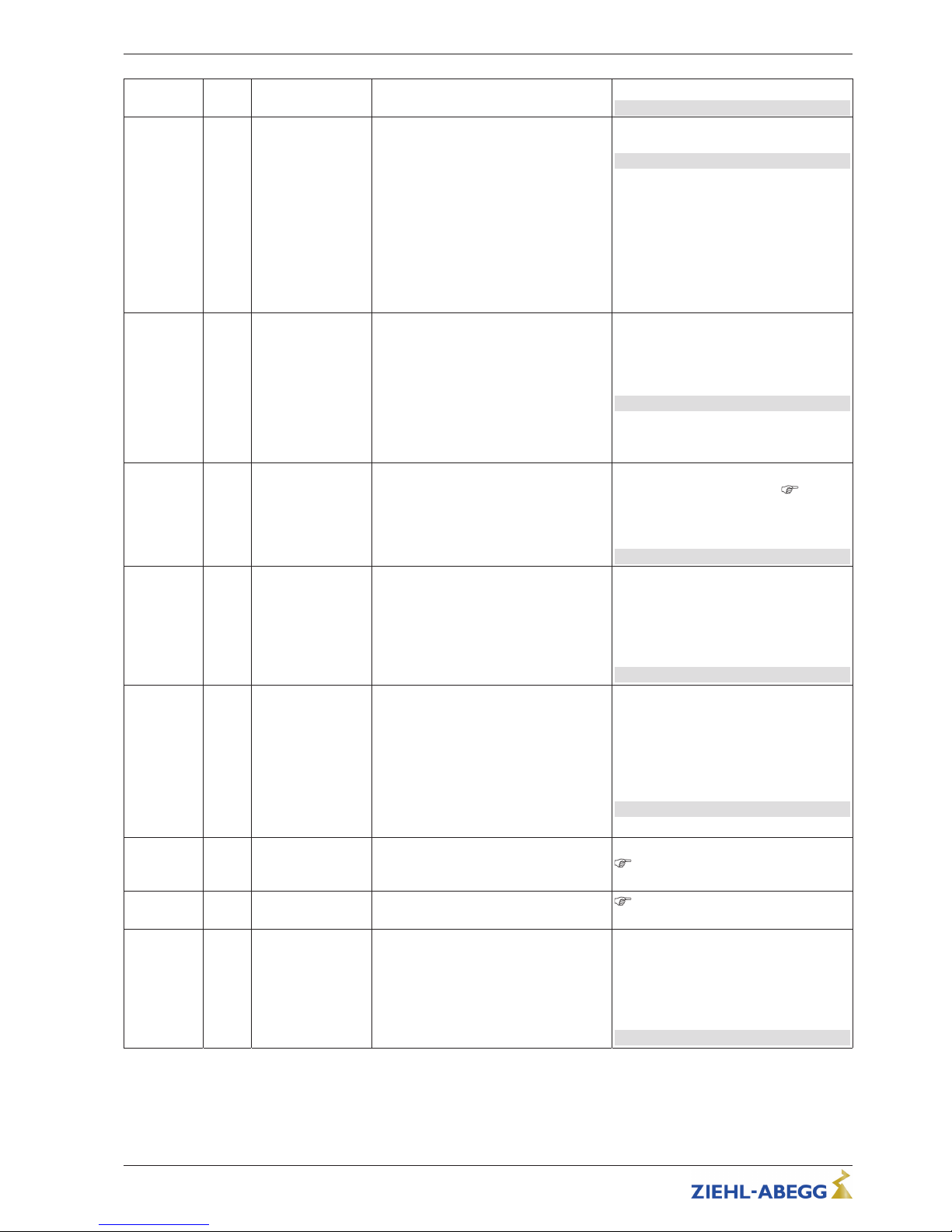
Display Code
Relay
K1
Explanation
Reaction of device
Adjustment
Temp. Man-
ager
2
energized 13 - 14
bridged
Temperature management active
The device has an active temperature
management to protect it from damage
due to too high inside temperatures. In
case of a temperature rise above the
fixed limits, the modulation is reduced
linearly. To prevent the complete system
being switched off externally (in this operation permissible for the controller) in
case of reduced operation due to too
high an internal temperature, no fault
message is sent via the relay.
With a drop in temperature the modulation rises again llinear.
Check cooling of the controller.
Line Fault 4
de-energized, 13 14 interrupted
Line failure
The device is provided with a built-in
phase-monitoring function for the mains
supply. In the event of a mains interruption (failure of a fuse or mains phase) the
unit switches off after a delay (approx.
200 ms).
Only functioning with an adequate load
for the controller.
Following a shutoff, a startup attempt is
made after approximately 5 seconds, if
the voltage supply is high enough. This
keeps occurring until all 3 supply phases
are available again.
Check line voltage.
IGBT Fault
Earth fault
6
de-energized, 13 14 interrupted
IGBT Fault
Earth fault or short-circuit at inverter output.
The device switches off, renewed attempt to start after about 60 s
Code 9.
Final switch off when error is detected
after the third start attempt at an interval
< 60 s.
Reset by enable or line voltage ON/OFF.
DC under-
voltage
7
de-energized, 13 14 interrupted
Intermediate undervoltage
Intermediate circuit voltage below a fixed
limit for longer than 75 s.
The modulation is switched off immediately at undervoltage, error message
after 75 s.
Automatic switching back on and switching off of error message when the voltage
exceeds the fixed limit for at least 5 s.
Check line voltage.
DC overvolt-
age
8
de-energized, 13 14 interrupted
Intermediate circuit overvoltage
Intermediate circuit voltage above fixed
limit for longer than 75s.
Reason for excessively high line voltage
or alternator motor operation.
The modulation is switched off immediately at overvoltage, error message after
75 s.
Automatic switching back on and switching off of error message when the voltage
drops below the fixed limit for at least 15
s.
Check line voltage.
Prevent generator motor operation.
IGBT warn-
ing
9
energized 13 - 14
bridged
IGBT warning
IGBT cooling down period for approx.
60 sec.
Final shutoff after 2 cooling-off intervals
Code 6.
Communica-
tion
10
de-energized, 13 14 interrupted
Communication fault
MODBUS communication interrupted
description MODBUS communication
Line under-
volt.
12
de-energized, 13 14 interrupted
Line voltage too low
Line voltage below a fixed limit for longer
than 75 s.
The modulation is switched off immediately at undervoltage, error message
after 75 s.
Automatic switching back on and switching off of error message when the voltage
exceeds the fixed limit for at least 5 s.
Check line voltage.
Operating Instructions Fcontrol Basic – model series FSDM2.5..50AM Events / Fault signals
L-BAL-E174-GB 1704 Index 005 Part.-No.
41/49
Page 42
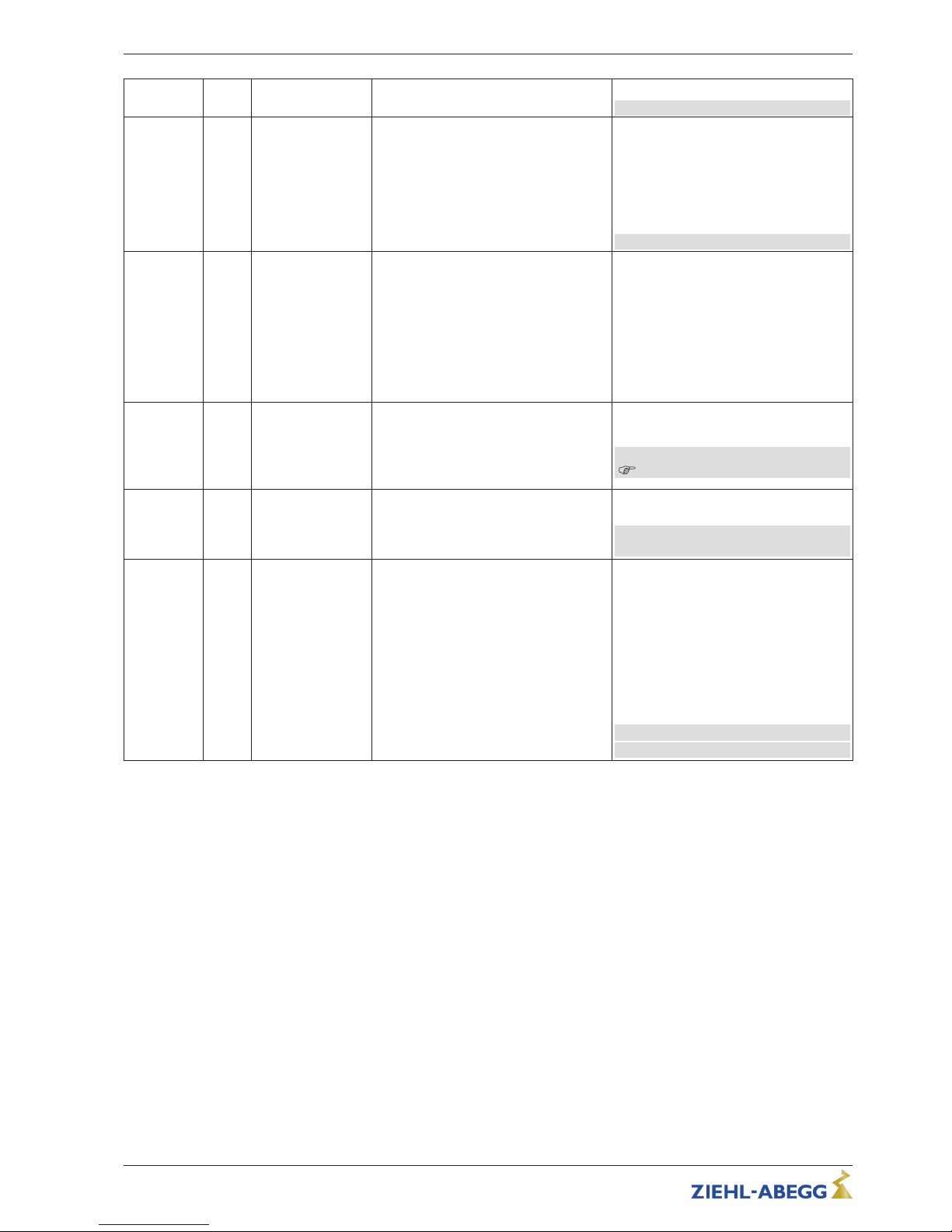
Display Code
Relay
K1
Explanation
Reaction of device
Adjustment
Line over-
voltage
13
de-energized, 13 14 interrupted
Line voltage too high
Line voltage above fixed limit for longer
than 75 s.
The modulation is switched off immediately at overvoltage, error message after
75 s.
Automatic switching back on and switching off of error message when the voltage
drops below the fixed limit for at least 15
s.
Check line voltage.
Peak current 14
de-energized, 13 14 interrupted
Error Peak current
If the output current increases above the
specified limit (even in a short timeframe) the device will switch-off.
After a switch off the controller waits for
30 seconds then the controller attempt a
start.
If 10 switch offs take place consecutively
within 60 s (time to next respective error),
final switch off takes place with an error
message.
Should no further switch off be exceeded
in 90 sec. the counter will be reset.
Motor fault 15
de-energized, 13 14 interrupted
Motor fault
A connected thermostat or thermistor
has tripped the circuit or interruption between both terminals “TB / TP”.
Plug for “TP” or “TP” in wrong positions.
The unit cuts out and does not switch on
again.
Check motor and connection then reset
(
Motor protection).
Output filter 16
de-energized, 13 14 interrupted
Sine filter to hot
(only in version with integrated sine filter)
Switch off at to high temperature, restarting after cooling down.
Check temperature in controller, Check
cooling of the controller.
Overload 17
de-energized, 13 14 interrupted
Overload fault
The controller was switched off by the
current limitation.
The error is set after detecting 4 times
(I
2
t-process; maximum overload applied
for 60 s).
After every detection (IGTB Recovery
Flag is set) there is a 30 s wait until a
new attempt is started.
The respective errors must alway have a
shorter interval than 5 minutes (started
after restart). The modulation is switched
off immediately after every detection.
Check load of the device.
Reset by enable or line voltage ON/OFF.
Operating Instructions Fcontrol Basic – model series FSDM2.5..50AM Events / Fault signals
L-BAL-E174-GB 1704 Index 005 Part.-No.
42/49
Page 43
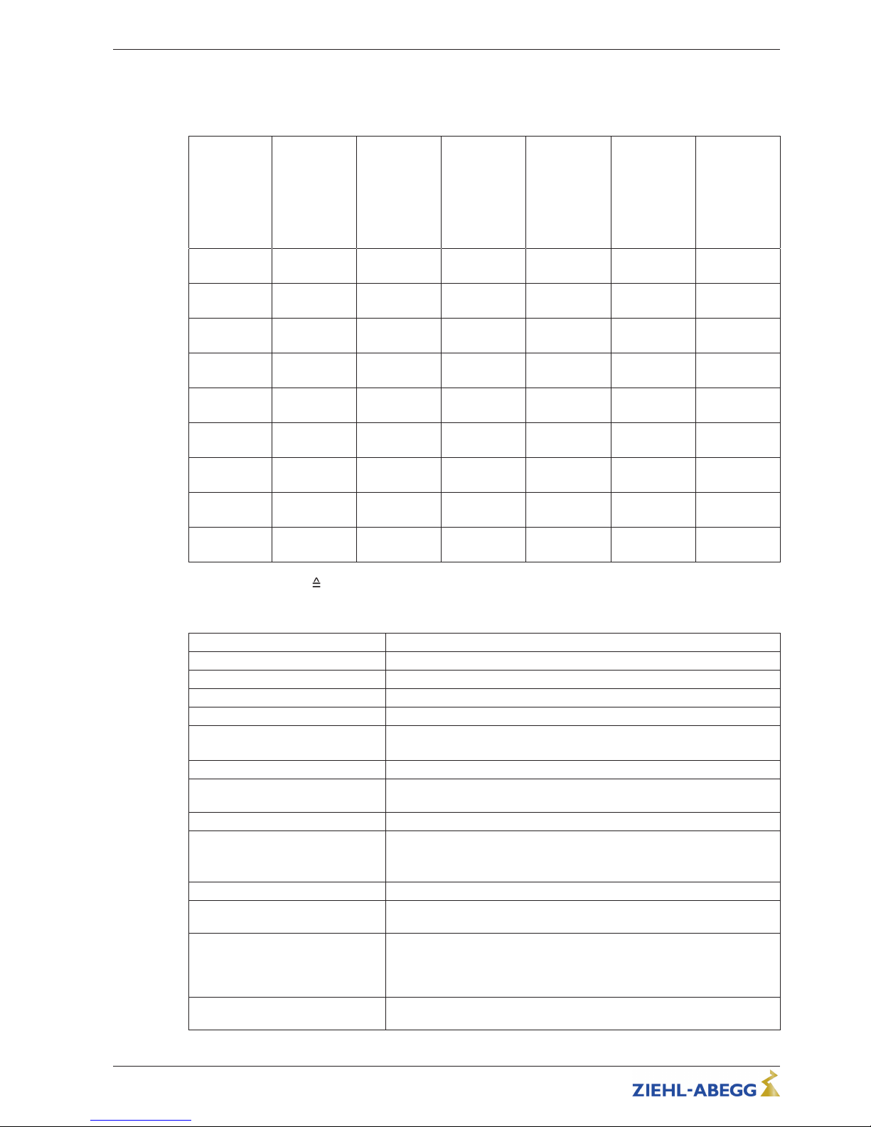
12 Enclosure
12.1 Technical data
Type
(Part-No.)
Rated current
Output
{1}
[A]
Rated current
(I fundamental
component @
50 Hz)
Input
{2}
[A]
Rated temper-
ature
[°C]
max. line fuse
{3}
[A]
max. heat dis-
sipation
{2}
[W]
Weight
[kg]
FSDM2.5AM
(308252)
2.5
2.5
(2.3)
40 6 50 2.9
FSDM5AM
(308240)
5.0
4.8
(4.5)
55 10 90 5.6
FSDM8AM
(308241)
8.0
7.1
(6.6)
40 10 140 6.5
FSDM10AM
(308260)
10.0
9.4
(8.6)
55 16 200 7.0
FSDM16AM
(308303)
16.0
15.2
(14,0)
40 20 360 7.2
FSDM22AM
(308315)
22.0
19.2
(17.7)
40 25 520 14.5
FSDM32AM
(308317)
32.0
27.6
(25.7)
50 35 700 29.6
FSDM40AM
(308319)
40.0
34.0
(31.5)
50 50 790 29.6
FSDM50AM
(308321)
50.0
47.5
(43.2)
50 63 910 32.8
{1} Rated current output
current indication rating plate @ rated voltage, @ rated temperature (cos φ 0.8 at the output).
{2} At rated voltage (cos φ 0.8 at the output), values for different specifications on request.
{3} Max. line fuse on site (line protection fuse) according to EN 60204-1 Classification VDE0113 Part 1
Line voltage* 3 ~ 208...480 V (-15 ... +10 %), 50/60 Hz
Nominal voltage 400 V
Maximal output voltage approx. 95 % from U
line
Switching frequency 16 kHz
Power factor > 0.9
Input resistance for speed setting
signal
for input 0...10 V: R
i
> 100 kΩ
for 0...20 mA input: R
i
= 100 Ω
Voltage supply for external devices +24 V ± 20 %, I
max
70 mA
Heat dissipation in standby operation
approx. 3 W
Output 10 V I
max
10 mA (short-circuit-proof)
Digital input “D1” Input resistance: R
i
approx. 4 kΩ
Voltage range high level: 10....30 V DC
Voltage range low level: 0....4 V DC
Max. contact rating of the relay 2 A / 250 V AC
Max. permissible ambient temperature for operation
55 °C
Min. permissible ambient temperature
0 °C (if mains voltage is not switched off up to -20 °C)
To avoid condensation the device must be continuously energized due to
the application of heat, with interruptions such that cooling to the point of
condensation does not occur.
Permissible temperature range for
storage and transport
-30...+80 °C (FSDM22: -30... +70 °C)
Operating Instructions Fcontrol Basic – model series FSDM2.5..50AM Enclosure
L-BAL-E174-GB 1704 Index 005 Part.-No.
43/49
Page 44
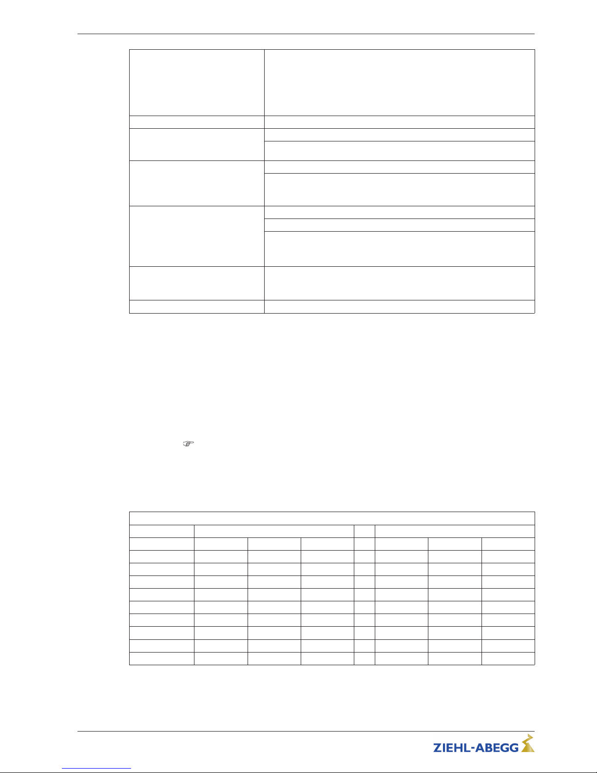
Permissible installation height 0...4000 m amsl
≤ 1000 m: no limitation
> 1000 m: max. permissible output current = current indication name plate
minus 5 % / 1000 m
> 2000 m: max. permissible line voltage = max. voltage indication name
plate minus 1.29 % / 100 m
Permissible rel. humidity 85 % no condensation
Electromagnetic compatibility for the
standard voltage 230 / 400 V according to DIN IEC 60038
Interference emission EN 61000-6-3 (domestic household applications)
Interference immunity EN 61000-6-2 (industrial applications)
Harmonics current According to EN 61000-3-2 (see Electrical installation / Harmonics current)
Please ask manufacturer for the individual harmonic oscillation levels of
the current as a percentage of the fundamental oscillation of the rated
current.
Max. leakage current according to
the defined networks of
DIN EN 60990
FSDM2.5/5/8AM < 3.5 mA
FSDM10/22/32/40/50AM > 3.5 mA
FSDM16AM (depending on applied mains voltage)
< 3.5 mA @ < 480 V
≥ 3.5 mA @ ≥ 480 V
Vibratory strength
(for vertical installation, i.e. cable
inlet down).
Broadband noise (simulated life-endurance test) in accordance with
EN 61373, category 1 class B.
Shock test according to EN 61373, category 1
Housing protection
IP54
* Regarding the mains connection, these devices are to be classified as category “C2” devices according to the relevant
DIN EN 61800-3. The increased requirements placed on electrical interference > 2 kHz for category “C1” devices are
complied with in addition.
12.1.1 Max. load dependent on ambient temperature and line voltage.
The maximum permissible temperature for the rated current at rated voltage is specified as rated
temperature.
Since the dissipation of the power loss (heat development) in the device is decisively dependent on
the ambient temperature, the max. load must be reduced at an ambient temperature above the rated
temperature (
following table)!
The average value measured during a 24 h period must be 5 K under the max. ambient temperature.
For installation in a switch cabinet, the device’s dissipation and its possible affect on the ambient
temperature must be taken into consideration!
Since the power loss in the device increases with rising line voltage, the following table must be
observed.
Maximal load depending on line voltage and ambient temperature
Type
208 V (-15 %)...415 V (+6 %)
over 415 V (+6 %)...480 V (+10 %)
40 °C 50 °C 55 °C
40 °C 50 °C 55 °C
F(S)DM2.5(A)M 2.5 A 2.2 A 2.0 A
2.5 A 1.8 A 1.6 A
F(S)DM5(A)M 5.0 A 5.0 A 5.0 A
5.0 A 5.0 A 5.0 A
F(S)DM8(A)M 8.0 A 7.0 A 6.5 A
8.0 A 6.5 A 6.0 A
F(S)DM10(A)M 10.0 A 10.0 A 10.0 A
10.0 A 10.0 A 10.0 A
F(S)DM16(A)M
16.0 A 13.0 A 12.0 A
14.5 A 12.5 A 11.5 A
FSDM22(A)M
22.0 A 18.0 A 15.3 A
22.0 A 17.0 A 14.5 A
FSDM32(A)M
32.0 A 32.0 A 30.0 A
32.0 A 32.0 A 30.0 A
FSDM40(A)M
40.0 A 40.0 A 37.0 A
40.0 A 40.0 A 35.0 A
FSDM50(A)M
50.0 A 50.0 A 48.0 A
50.0 A 50.0 A 46.0 A
Operating Instructions Fcontrol Basic – model series FSDM2.5..50AM Enclosure
L-BAL-E174-GB 1704 Index 005 Part.-No.
44/49
Page 45
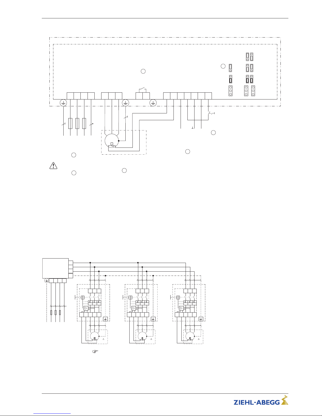
12.2 Connection diagram
Fcontrol Basic FSDM...(A)M
L3L2L1
PE
Netz
Line
3 ~ 208...480 V 50/60 Hz
L1 L2 L3
U V W
TB/TPTB/
TP
E1 D1 GND 10V 24V
Eingang
Input
0...10 V
0...20 mA
0...100 % PWM
+
4
Digital In 1
Analog In 1
24 V DC Out
10 V DC Out
01
Aus / Ein
Off / On
10V
+
13 14
K1
Kontaktbelastung
Contact rating
max. AC 250 V 2 A
7
M
3 ~
U
V W PE TB
Y/Δ
q
3 ~ Motor
mit eingebauten Thermostatschaltern
with internal thermostats
3
TB
1
J1 E1,1 E1,2
TB
TP
0...20 mA
0...10 V
(10 V PWM)
15...28 V PWM
6
Temperaturfühler
Thermistors
TP =
Thermostatschalter
Thermostats
TB =
N
N
5
UMUN13K2
14.01.2016
2
Nicht für IT-System geeignet!
Not suitable for IT-System!
TB/TP In
1 Line 3 ~ 208 V...480 V, 50/60 Hz ("N" - connection only available for FSDM22)
2 Not suitable for IT system!
3 3 ~ Motor with internal thermostats
4 Input: 0...10 V, 0...20 mA, 0...100 % PWM
5 Enable Device Off / On
6 TP = thermistors, TB = thermostats
7 Contact rating max. 2 A / 250 V AC
12.2.1 Connection suggestion for several motors with motor protection units type STDT
•
Full motor protection by switch-off when activating the attached thermostat switches “TB”. Reset after
malfunction by key press.
•
Line protection: A thermal over current sensor and a magnetic short circuit releasing elements are the
parts of the integral line protection. Adjustment to the thermal overcurrent sensor to the max. permissible
current of the connected cable (max. line fuse 80 A).
•
No cut-off if the mains supply is interrupted
3~ Controller
UPE V W
NL1 L2 L3
L3 NL2L1
PE
3~ 208 .. 415 V
4 mm²
KT00005H
27.09.2007
1 3
2 4 6
I>
5
STDT16
TB TB
I> I >
3~ Motor
M
3~
PE
V WU
TB
TB
4 mm²
1,5 mm²
1 3
2 4 6
I>
5
STDT16
TB TB
I> I >
3~ Motor
M
3~
PE
V WU
TB
TB
4 mm²
1,5 mm²
1 3
2 4 6
I>
5
STDT16
TB TB
I> I >
3~ Motor
M
3~
PE
V WU
TB
TB
4 mm²
1,5 mm²
Y/
Y/ Y/
Consider max. terminal load Operating Instructions!
(General example, data for the connection of the controller dependent on the used type of device)
Operating Instructions Fcontrol Basic – model series FSDM2.5..50AM Enclosure
L-BAL-E174-GB 1704 Index 005 Part.-No.
45/49
Page 46
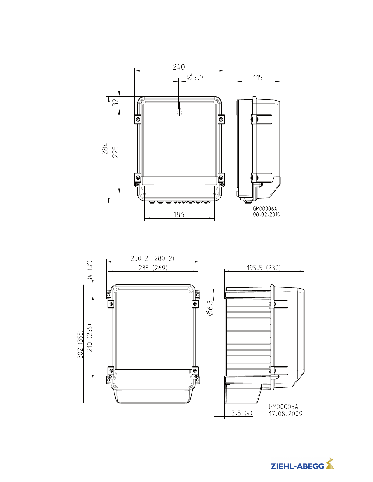
12.3 Dimensions [mm]
FSDM2.5M
FSDM5/8/10/16M (FSDM22M)
Operating Instructions Fcontrol Basic – model series FSDM2.5..50AM Enclosure
L-BAL-E174-GB 1704 Index 005 Part.-No.
46/49
Page 47
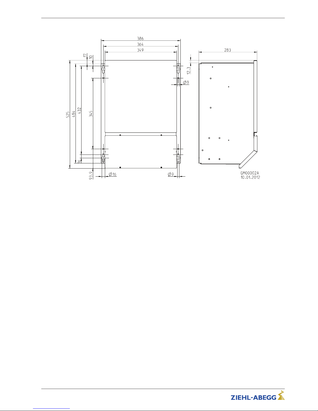
FSDM32/40/50M
Operating Instructions Fcontrol Basic – model series FSDM2.5..50AM Enclosure
L-BAL-E174-GB 1704 Index 005 Part.-No.
47/49
Page 48

Operating Instructions Fcontrol Basic – model series FSDM2.5..50AM Enclosure
L-BAL-E174-GB 1704 Index 005 Part.-No.
48/49
12.4 Index
B
bypass switching 19
C
characteristic curve 32
control cable 15
current increase 31
current-operated protective
devices 16
D
DC-brake 34
diagnostics menu 39
direction of rotation 33
E
edge frequency 31
enable 19
H
heat dissipation 43
I
Input resistance 43
L
leakage current 16, 44
line fuse 43
line impedance 15
line protection 16
linear characteristic 31
M
mains 15
Maximum frequency 31
Minimum space requirement 9
motor feed cable 15
motor leads 16
Motor protection 17
motor protection unit 16
O
one-quadrantdrives 8
Outdoor installation 13
output voltage 31
P
pin code 24
PIN input 24
PTC 17
PWM signal 17
R
Rampdown time 32
Rampup time 32
relays 19
Reset 19, 27
resonances 36
S
Sine filter 8
start voltage 32
Suppression 36
T
Technical data 3, 43
temperature management 41
torque 32
U
U/f curve 31
Page 49
12.5 Manufacturer reference
Our products are manufactured in accordance with the relevant international regulations. If you have
any questions concerning the use of our products or plan special uses, please contact:
ZIEHL-ABEGG SE
Heinz-Ziehl-Straße
74653 Künzelsau
Telephone: +49 (0) 7940 16-0
Telefax: +49 (0) 7940 16-504
[email protected]
http://www.ziehl-abegg.de
12.6 Service information
If you have any technical questions while commissioning or regarding malfunctions, please contact
our technical support for control systems - ventilation technology.
phone: +49 (0) 7940 16-800
Email: [email protected]
Our worldwide contacts are available in our subsidiaries for deliveries outside of Germany, see
www.ziehl-abegg.com.
If you make returns for inspections or repairs we need certain information in order to facilitate focused
trouble shooting and fast repair. Please use our repair ticket for this. It is provided to you after you
have consulted our support department.
In addition, you can download it from our homepage. Support - Downloads - General documents.
Operating Instructions Fcontrol Basic – model series FSDM2.5..50AM Index
L-BAL-E174-GB 1704 Index 005 Part.-No.
49/49
 Loading...