

Page 1
ZIEHL industrie – elektronik GmbH + Co KG
Daimlerstr.13, 74523 Schwäbisch Hall, Germany
+ 49 791 504-0, [email protected], www.ziehl.de
Quick Guide TR800Web
updated: 2016-10-06/Fz
from Firmware: 2.0.3
Hardware Version -HW1
TR800Web 12280-0755-01 Seite 1 / 8 www.ziehl.de
- Universal Relay
Detailed operating manual see: http://www.ziehl.com/de/produkte/?view=detail&detail=38
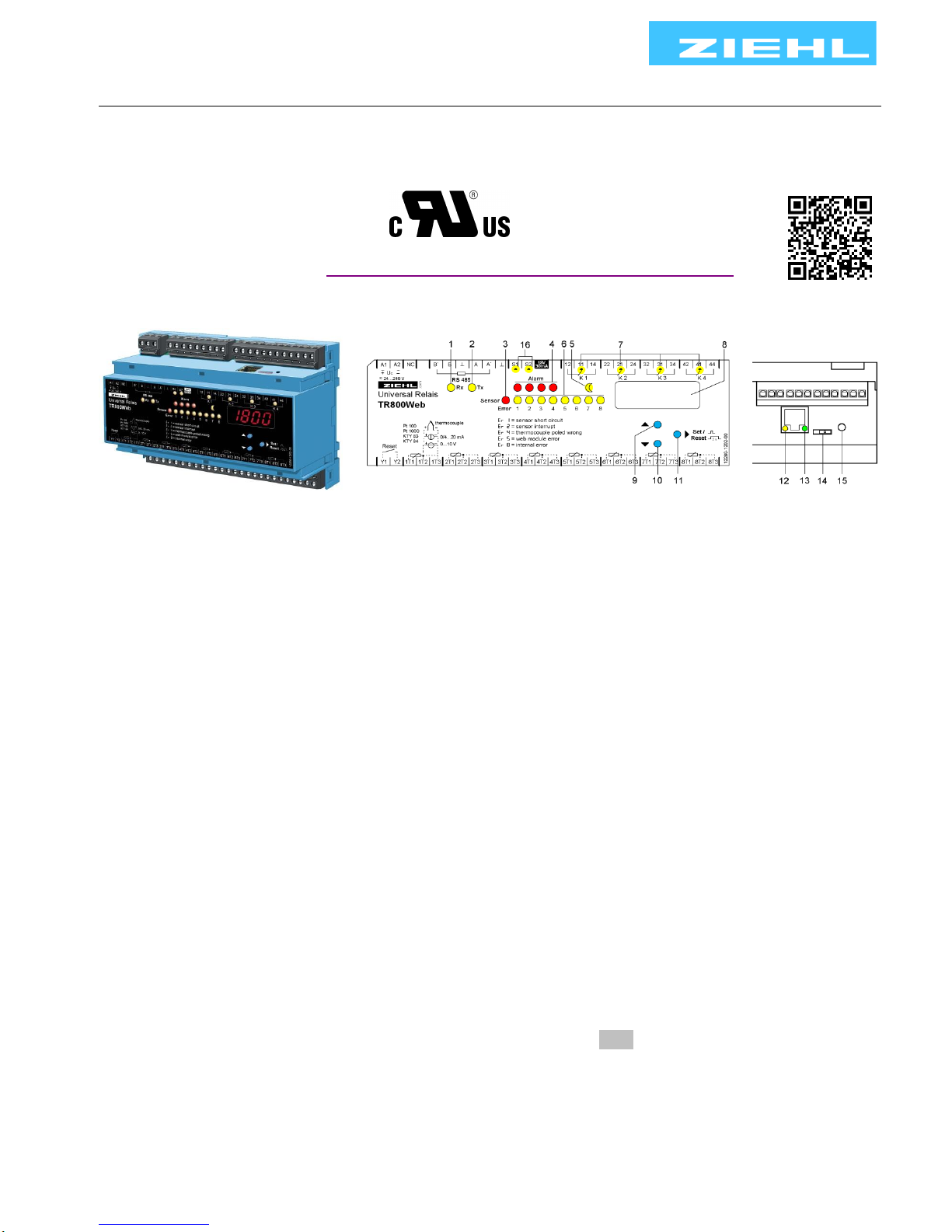
1 Display and controls
1, 2 LEDs (yellow) RS485 interface
Rx flashes briefly: Unit is receiving data via the RS485 interface
Tx flashes briefly: Unit is transmitting data via the RS485 interface
Rx and Tx flash/illuminate during firmware update
3 LED (red) Sensor error
Illuminated: Fault in a sensor circuit
4 LEDs (red) alarm
Illuminated: Alarm (1-4) has occurred
Flashes briefly (1:4): Response delay is running
Flashes long (4:1): Backshift delay is running
Flashes uniformly (1:1): Ready for reset, reset with key
Press "SET/RESET" ≥ 2s or ext. Reset Y1/Y2
5 LED (yellow) Night
Illuminated: Limits for "Night" (can be set via browser) are active
6 LEDs (yellow) sensors
Illuminated: Displays the sensor value belonging to the LED in the digital display
Flashes: Sensor error in the corresponding sensor circuit
7 LEDs (yellow) relay state
Illuminated: The relay belonging to the LED is picked up
Off: The relay belonging to the LED is released
8 Digital display (4 digits)
Display of sensor value, error codes
Display of menu and configuration mode
9, 10 Up button / Down button
Change into the menu mode (see Operating instructions Point 8.3)
11 Set/Reset button
Press briefly: Displays the next sensor (sensor LED illuminates)
Press for 10 s: Displays the software version (e.g. 0-00)
12 LED (yellow) Displays Ethernet transmission speed
Off: 10 Mbps On: 100 Mbps
13 LED (green) Displays Ethernet data traffic
Flashes during active data transmission
Page 2
TR800Web 12280-0755-01 Seite 2 / 8 www.ziehl.de
14 IP address slide switch
Towards Ethernet jack: IP address 10.10.10.10
Towards reset button: IP address User (set via web browser)
15 Webserver reset button
Internal webserver restarts when pressed (duration ca. 1 minute)
16 LED (yellow) input state S1 and S2
On: input Sx active
2 Installation
The unit can be installed as follows:
Installation in switchgear cabinet on 35 mm mounting rail according to EN 60715
With screws M4 for installation on walls or panel. (additional latch not included in delivery)
Connection according to connection plan or type plate.
3 Important Information’s
DANGER!
Hazardous voltage!
Will cause death or serious injury. Turn off and lock out all power
supplying this device before working on this device.
Observe the maximum temperature permissible when installing in switching cabinet. Make sure
sufficient space to other equipment or heat sources. If the cooling becomes more difficult e.g.
through close proximity of apparatus with elevated surface temperature or hindrance of the
cooling air, the tolerable environmental temperature is diminishing.
A circuit-breaker or switch must be situated within easy reach of the
unit and fused. Installation excess current protection should be ≤ 10 A.
Before switching on make sure that the operational voltage Us of the
type- plate and the mains voltage are the same.
ATTENTION! When all relays are programmed in operation current mode (= pick up
at alarm), a loss of the supply voltage or an instrument failure can remain
unidentified.
When the relay is applied as control instrument, the operator must ensure, that
this error is recognized by regular examinations.
We recommend to program and accordingly evaluate at least one relay in the
closed-circuit current mode
!!!
Page 3
TR800Web 12280-0755-01 Seite 3 / 8 www.ziehl.de
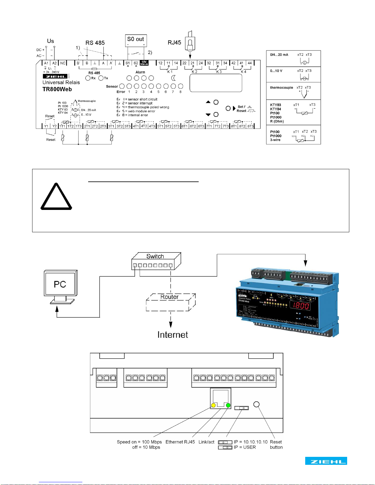
4 Connection Plan
1) Terminating resistor active: Bridge A to A’ and B to B’
2) Option
ATTENTION! Connection of sensors
The inputs 1T1, 1T2, 1T3 to 8T3 and RESET Y1, Y2, S1, S2 are not potentially
separated from output RS485. Temperature-sensors must have a sufficient
insulation.
Only signals according to SELV (Safety Extra Low Voltage) may be connected.
The pluggable terminals of the measuring inputs have a special contact-material
and may only be used for the connection of the sensors.
4.1 Connection to network and controls
!
Page 4
TR800Web 12280-0755-01 Seite 4 / 8 www.ziehl.de
S 1
100
1000
83
84
th..
0-10
0-20
4-20
R500
R30.0
diff
S 2
100
1000
83
84
th..
0-10
0-20
4-20
R500
R30.0
diff
Sensor
1
Sensor
2
Sensor
3
Sensor
4..8
,192
168
´ 1
_ 95
Dhcp
Off / on / fail
IP
AL 1
AL 2
AL 3
AL 4
S 3 – S 8
Sensor
typ
...
...
= Reset
= Down
= Up
>2s
= Set
IP-
Thermocouples (th..)
thb = Typ B
thn = Typ E
thj = Typ J
thk = Typ K
thl = Typ L
thn = Typ N
thr = Typ R
ths = Typ S
tht = Typ T
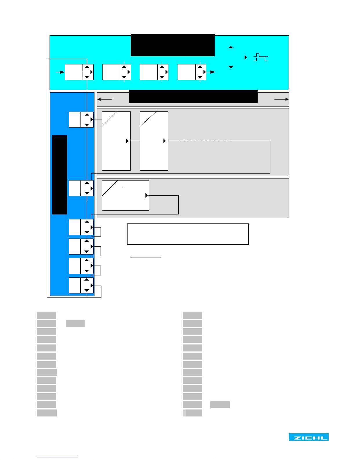
5 Short operating diagram
8typ 8 type of sensor
8S 1 8 … 8S 8 8 sensors 1 to 8
8 nc8 not connected
8 1008 type Pt 100
810008 type Pt 1000
8 838 KTY 83
8 848 KTY 84
8th . .8 thermocouples
80-108 voltage input 0-10 V
80-208 current input 0-20 mA
84-208 current input 4-20 mA
8r5008 resistance 500 Ohm
8r30.08 resistance 30 K Ohm
8diff8 difference
8IP 8 IP- address
8IP- 8 IP- address
8,1928 1 digit of IP- address
8'1688 2 digit of IP- address
8´ 18 3 digit of IP- address
8_ 958 4 digit of IP- address
8dhcp8 DHCP
8 off8 DHCP off
8 on8 DHCP on
8faIl8 DHCP missed
8Al 18 ... 8Al 48 alarms 1 to 4
8boot8 webserver starts
Menu mode
Info mode
Display mode
normal operation
error messages:
Er 1 = sensor short circuit
Er 2 = sensor break
Er 4 = thermocouple poled wrong
Er 5 = no contact to web-module
Er 8 = error in unit
Er 9 = error in parameters
Sensors assigned to an alarm are lighting (yellow)
Sensors having caused an alarm are blinking (yellow)
Page 5
TR800Web 12280-0755-01 Seite 5 / 8 www.ziehl.de
6 Switching on the unit
Apply supply voltage to terminals A1 and A2,
Ca. 2s long, all LEDs and the digital display illuminate ( 8.8.8.8. )
The TR800Web is now ready to operate
In the digital display, boot flashes (alternating with sensor value), the integrated webserver
starts (duration ca. 1-2 minutes). After boot extinguishes, the unit can be addressed via its
interfaces.
6.1 Find the unit in the network
Prerequisite: Web browser Internet Explorer 7,8 or Firefox 3 (tested).
The TR800Web provides four facilities to find itself in the network:
6.1.1 DHCP server
In the network, there is a DHCP server; newly added units automatically are assigned an IP
address
Query of the IP address in the unit
Press the DOWN button 2x, then the SET button
IP address appears in the digital display
Status of DHCP query is displayed ( off / on / FAIL )
Start web browser and enter the IP address in the address line [Return]
The TR800Web homepage opens in the web browser
Close the login window with the OK button (without user name and without password)
If the network logon fails via DHCP, a network configuration will be performed based on zeroconf (IP
= 169.254.x.x).
6.1.2 Default IP- Address 10.10.10.10
! Use this setting for configuration only.
Push slide switch to IP 10.10.10.10 (sketch Point 8.8)
Requires a reboot of webserver (press RESET button), in the digital display boot
flashes (start duration ca. 1 min)
User management is deactivated, http-Port = 80 und https-Port = 443
Note: The following actions can only be performed with administrator rights.
Enter this command into your PC in the input prompt (command line):
route add 10.10.10.10 xxx.xxx.xxx.xxx (xxx.xxx.xxx.xxx= IP address of PC)
Route for the TR800Web
ping 10.10.10.10
Connection test
TR800Web replies
Reply from 10.10.10.10: Bytes=32 Time=3ms TTL=32
Reply from 10.10.10.10: Bytes=32 Time=1ms TTL=32
Ping statistic for 10.10.10.10:
Package: Sent = 4, Received = 4, Lost = 0 (0% loss),
Connection okay
Page 6
TR800Web 12280-0755-01 Seite 6 / 8 www.ziehl.de
Start web browser and enter the IP address (10.10.10.10) in the address line [Return]
The TR800Web homepage opens in the web browser
Close the login window with the OK button (without user name and without password)
Make the basic network settings
Push the slide switch to IP USER (sketch Point 8.8)
Requires a reboot of webserver (press RESET button), in the digital display boot flashes
(start duration ca. 1-2 minutes
Note: The settings made in the web browser under "Network" are only effective after the slide switch
is switched to IP User and the unit has been rebooted (press RESET button).
6.1.2.1 UPnP
Available for Windows starting from Win XP
Note: not available if the http port has been switched off
Start network browser (network environment),
("Symbols for show Network UPnP devices" must be active)
Double click on the device found
The TR800Web homepage opens in the web browser
Close the login window with the OK button (without user name and without password)
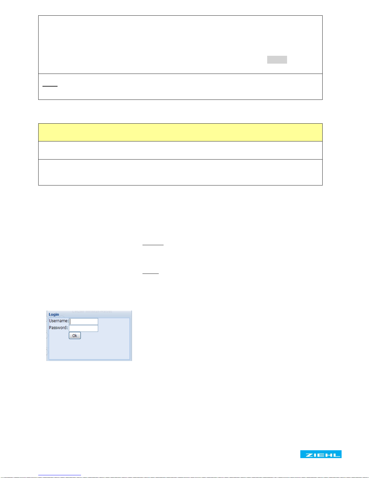
6.2 Information about the login window
Closing the login window (click on OK button) is delayed a couple of seconds as data still needs to be
transmitted in the background.
If the user admin/access control is inactive (default) the login window is not visible.
The user management/access control is always deactivated if the slide switch is set to IP=10.10.10.10
(see Points 4.1 and 6.1.2).
If the user admin/access control is active (see Point 8.15), the Username and Password must be entered.
Entry is case-sensitive.
Guest access (if activated, see Point 8.15) is made by logging in without any user name and password.
Guests can only view the "Measurements" and "Sensors" web pages. It is not possible to change the
parameters.
Page 7
TR800Web 12280-0755-01 Seite 7 / 8 www.ziehl.de
7 Troubleshooting
boot appears in the digital display
Cause
This is not an error.
The internal webserver is starting up.
Remedy
After switching on the network, the internal webserver needs app. 1 min. until it starts.
After that, the digital display extinguishes.
After performing a software update, the webserver automatically reboots.
Er 5 appears in the digital display
Cause
The internal webserver is not working correctly
Remedy
Do a reset; press the reset button on the unit (see Point 8.8) or switch off the unit and
then back on.
After max. 2 min, Er 5 and boot should no longer be flashing in the display.
Er 8 appears in the digital display
Cause
Internal device error
Remedy
Switch unit off and back on. If the error message continues to appear, the unit must be
returned to the factory for repair
User name/password not known
Remedy
See 8.9.2 Set default IP address 10.10.10.10
User management is deactivated, http-Port = 80 and https-Port = 443
Login window cannot be closed
Remedy
Close the browser window and then reopen it
8 Technical Data
Rated supply voltage Us
AC/DC 24 – 240 V
Tolerance
Power consumption
DC 20,4 - 297 V
< 4 W
AC 20 - 264 V 45-62 Hz
< 13 VA
Relay output
4 x 1 changeover (CO)
UL electrical ratings:
E214025
250 V ac, 5 A, resistive
240 V ac, 1/2 hp
120 V ac, 1/4 hp
B 300 – pilot duty, UL 508
Nominal operational current Ie
AC15
Ie = 3 A Ue = 250 V
DC13
Ie = 2 A Ue = 24 V
Ie = 0,2 A Ue = 125 V
Ie = 0,1 A Ue = 250 V
Recommended fuses for contact
T 3,15 A (gL)
Page 8
TR800Web 12280-0755-01 Seite 8 / 8 www.ziehl.de
Inputs
Pt 100, Pt 1000
-199…+860 °C, according EN 60751
KTY83, KTY84
-55…+175 °C, -40…+150 °C
Thermocouples
Type B, E, J, K, L, N, R, S, T EN 60 584, DIN 43 710
Voltage- / Current input
0-10 V, 0/4-20 mA
Measuring of resistance
0,0 … 500,0 Ω , 0…30,00 kΩ
Input Y1-Y2
Reset, app. 18 VDC / 3,5 mA
Input S1 and S2
for contact or S0-interface
Network-connection
10/100 MBit Auto-MDIX
RS 485 interface
Baud rate
4800, 9600, 19200 Baud
Parity
N, O, E (none, odd, even)
Wire length
1000 m at 19200 Baud
Test conditions
EN 61010-1
Rated impulse voltage
4000 V
Overvoltage category
Contamination level
III
2
Rated insulation voltage Ui
300 V
On-time
100 %
Galvanic insulation / Test-voltage
Ethernet – sensors DC 750 V
Us – relays, sensors, Ethernet DC 3820 V
Relays – sensors, Ethernet DC 3820 V
Sensors – relays DC 3820 V
No galvanic insulation
RS485 – sensors – reset input Y1/Y2 – S1 – S2
Environmental conditions
Ambient temperature range
Storage temperature range
Altitude
Climatic conditions
External wiring temperature range
-20 °C ... +65 °C
-20 °C …+70 °C
Up to 2000 m
5 – 85 % rel. humidity, no condensation
-5 °C …+70 °C
Housing
Design V8, switchgear mounting
Dimensions (W x H x D)
140 x 90 x 58 mm
Mounting height / width
55 mm / 8 TE
Wire connection, one wire
each 1 x 1,5 mm2
Stranded wire with insulated ferrules
each 1 x 1,0 mm2
Stripping length
8 mm
Torque of screw
0,5 Nm (3,6 lb.in)
Protection class housing / terminal
IP 30 / IP 20
Fitting position
any
Installation
Snap mounting on mounting rail 35 mm according to EN
60 715 or with screws M 4
(2 additional bars, not included in delivery)
Weight
app. 370 g
Subject to technical changes
 Loading...