

Page 1
MINIPAN
®
digital panel meters, temperature
-
and mains controlling,
special purpose instruments for customer requirements www.ziehl.com
Operating manual
Limit Value Switch TR 210
datum / name : 13.12.2007 Fu Z. Nr.: 1185 0710.4
Page 1 of 24 Type: TR 210
ZIEHL industrie-elektronik GmbH + Co KG, Daimlerstr.13, D-74523 Schwäbisch Hall, Tel.: +49 791 504-0, Fax: -56, e-mail: info@ziehl.de
Page 2

Index Page
Application and short description ...................................................................................3
Overview of the functions...............................................................................................3
Connection plan.........................................................................................................3
Display- and operating elements ...................................................................................3
Programs .......................................................................................................................4
Important informations ...................................................................................................4
Installation......................................................................................................................6
Starting ..........................................................................................................................6
Display mode.............................................................................................................6
Menu mode................................................................................................................6
Parameter setting mode ............................................................................................6
Indication of the digital display ..................................................................................9
Operation Program 1 – 1 Sensor / 2 limit values .......................................................10
Operation Program 2 – 2 Sensors / per 1 limit value .................................................11
Operation Program 3 – 1 Sensor / 2 limit values day, 2 limit values night .................12
Operation Program 4 – 2 Sensors / per 1 limit value day and night...........................13
Operation Program 5 – 2 Sensors / difference in temperature S 2 minus S 1 ...........14
Operation Program 6 – 1 input 0–10 V or 0/4-10 mA / 2 limit values.........................15
Operation Program 7 – 2 inputs 0–10 V or 0/4-10 mA / per 1 limit value...................16
Operation Program 8 – 2 inputs 0–10 V or 0/4-10 mA / difference S 2 minus S 1.....17
Operation Program 9 – 2 Sensors / 2 Limits MIN/MAX .............................................18
Function diagram ......................................................................................................18
Factory setting and software version .............................................................................19
Error search and measures ...........................................................................................20
Technical data ...............................................................................................................20
Housing..........................................................................................................................22
datum / name : 13.12.2007 Fu Z. Nr.: 1185 0710.4
Page 2 of 24 Type: TR 210
ZIEHL industrie-elektronik GmbH + Co KG, Daimlerstr.13, D-74523 Schwäbisch Hall, Tel.: +49 791 504-0, Fax: -56, e-mail: info@ziehl.de
Page 3
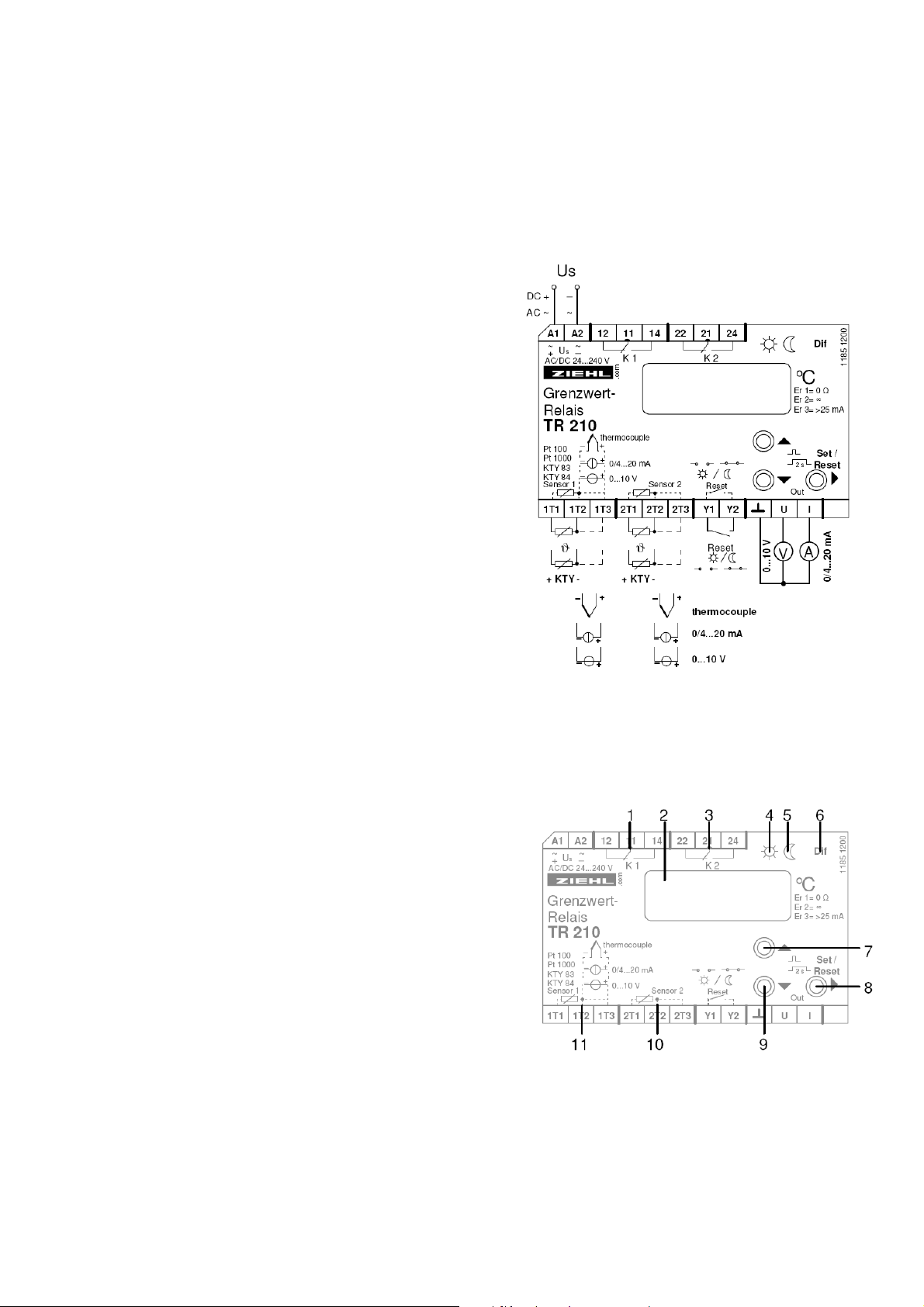
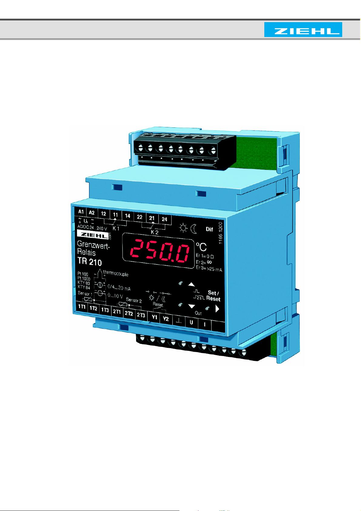
Connection Plan
Application and Short description
Control units type TR 210 control up to 2 limit values.
The TR 210 is used as:
• General temperature protection of machines and installations
• Temperature control unit, also for cooling applications
• Difference temperature controller unit for air-conditioning technology
Overview of functions
• 2 Sensor inputs:
• Pt 100, Pt 1000, KTY 83 or KTY 84
in 2- or 3-wire configuration
• Thermocouples
Type B, E, J, K, L, N, R, S, T
• Input signal DC 0-10 V;
DC 0/4-20 mA
• 0,1 °C resolution between
–199,9...999.9 °C
• 2 Relay outputs (each 1 change-over
contact)
• 1 Analogue output DC 0-10 V or
0/4-20 mA parameterizable (not potentially
separated from the inputs)
• Universal power supply AC/DC 24-240 V
• Several selectable programs
• Storage and indication of the measured
MIN- und MAX-values
• pluggable terminals
Display and operation parts
1, 3 LEDs state of relay
2 Digital display, 4 digits
4, 5 LEDs day/night switching
6 LED measuring of differences
7 Up pushbutton
8 Pushbutton set/reset
9 Down pushbutton
10, 11 LEDs sensor
datum / name : 13.12.2007 Fu Z. Nr.: 1185 0710.4
Page 3 of 24 Type: TR 210
ZIEHL industrie-elektronik GmbH + Co KG, Daimlerstr.13, D-74523 Schwäbisch Hall, Tel.: +49 791 504-0, Fax: -56, e-mail: info@ziehl.de
Page 4

Programs
9 programs (Pr), that are preset ex works, can be selected. Due to these programs, the
device can be adapted very easily to the application.
Choose the program, which fits to your application and after that change the parameters! In
case of changing the program, each parameter is being resetted to "factory setting".
(see chart " factory setting")
Choosing the programs:
When applying the power supply hold the pushbutton Set for 10 s. Then the program
(Pr 1 ... Pr 9) can be selected with the pushbuttons up/down and confirmed with Set.
Pr Input Limit value
1* 1 temperature sensor 2
2 2 temperature sensors 1 per sensor
3 1 temperature sensor 2 day and 2 night
4 2 temperature sensors 1 day and 1 night per sensor
5 2 temperature sensors 2 difference temperature
6 1x 0-10 V or 0/ 4-20 mA 2
7 2x 0-10 V or 0/ 4-20 mA 1 per input
8 2x 0-10 V or 0/4- 20 mA 2 difference
9 2 temperature sensors 2 MIN/MAX
* factory setting
Please note:
Pr 1, 2, 5-9: Y1 / Y2 = remote – reset (external)
Pr 3+4: Y1 / Y2 = switching day / night
Important Information
To use the equipment flawless and safe, transport and store properly, install and start
professionally and operate as directed.
Only let persons work with the equipment who are familiar with installation, start and use
and who have appropriate qualification corresponding to their function. They must
observe the contents of the instructions manual, the information which are written on the
equipment and the relevant security instructions for the setting up and the use of electrical
units.
The equipments are built according to DIN / EN and checked and leave the plant
according to security in perfect condition. To keep this condition, observe the security
instructions with the headline „Attention“ written in the instructions manual. Ignoring of the
security instructions may lead to death, physical injury or damage of the equipment itself
and of other apparatus and equipment.
If, in any case the information in the instructions manual is not sufficient, please contact
our company or the responsible representative.
Instead of the industrial norms and regulations written in this instructions manual valid for
Europe, you must observe out of their geographical scope the valid and relevant
regulations of the corresponding country.
datum / name : 13.12.2007 Fu Z. Nr.: 1185 0710.4
Page 4 of 24 Type: TR 210
ZIEHL industrie-elektronik GmbH + Co KG, Daimlerstr.13, D-74523 Schwäbisch Hall, Tel.: +49 791 504-0, Fax: -56, e-mail: info@ziehl.de
Page 5
Dangerous electrical voltage!
May lead to electrical shock and burn.
Before beginning of work switch unit and equipment free of voltage.
Observe the maximum temperature permissible when installing in switching
cabinet. Make sure sufficient space to other equipment or heat sources. If the
cooling becomes more difficult e.g. through close proximity of apparatus with
elevated surface temperature or hindrance of the cooling air, the tolerable
environmental temperature is diminishing.
Attention! Connecting the temperature sensors
The temperature sensors are connected to the clamps 1T1, 1T2, 1T3 and so on. These
pluggable terminals have a special contact material and may only be used for the connection
of the sensors.
When connecting 2 thermocouples they must be isolated from each other.
Attention! Universal power supply
The unit is equipped with an universal power supply, that is suitable for DC- and AC-voltages.
Before connecting the unit to the current, make sure that the allowed scope of voltage of the
control voltage Us, written on the lateral type plate, corresponds to the supply voltage of the
unit.
ATTENTION
Attention!
When all relays are programmed in operation current mode
(= pick up at alarm), a loss of the supply voltage or an instrument failure
can remain unidentified.
!
When the relay is applied as control instrument, the operator must ensure,
that this error is recognized by regular examinations.
We recommend to program and accordingly evaluate at least one relay
in the closed-circuit current mode.
datum / name : 13.12.2007 Fu Z. Nr.: 1185 0710.4
Page 5 of 24 Type: TR 210
ZIEHL industrie-elektronik GmbH + Co KG, Daimlerstr.13, D-74523 Schwäbisch Hall, Tel.: +49 791 504-0, Fax: -56, e-mail: info@ziehl.de
Page 6

Installation
The unit can be installed as follows:
• Installation in switchgear cabinet on 35 mm mounting rail according to EN 60715
• With screws M4 for installation on walls or panel. (additional latch included in delivery)
Connection according to connection plan or type plate.
Putting into operation
Decimal point behind the last digit:
Off = display mode, displays values of measuring inputs
On = menu mode, select the menu items
blinking = parameter setting mode
Display mode
Indication of the current sensor temperature. The temperature is shown in degrees
centigrade. The indication for voltage (0-10 V) and current (0/4-20 mA) can be scaled.
LED relay (K1, K2)
ON = relay picked up
LED sensor
ON = appropriate value in the display
flashes = sensor error
Function of buttons UP/DOWN
Push short change into menu mode
Push for > 2 s Display of the stored MIN- or MAX values of the chosen sensor
Function button SET/RESET
Push short
two sensors Display sensor 1 / sensor 2 (/ difference)
one sensor Display sensor / alarm limit 1 / alarm limit 2
Push for 2 s Reset restart interlock
Push for 4 s Display of chosen program
Push for 10 s Display of software version
Menu mode (Decimal point behind the last digit ON)
Selection of the menu items for changing the parameters. In the menu items for sensorand alarm parameterizing the LEDs indicate the special classification sensor-alarmday/night - difference.
Function button UP/DOWN
Push short Selection of menu item; Change into display mode
Function button SET/RESET
Push short Change into parameter setting mode
Parameter setting mode (Decimal point behind the last digit FLASHES)
LEDs indicate sensors and relays concerned by the selected parameter setting point as
well as day/night-switching and differentiation measurement.
Function button UP/DOWN
Press short/long Adjustment of parameter value (slow/fast)
Function button SET/RESET
Press short Storage of setting and choice of next parameter.
Change into menu mode after the last parameter
datum / name : 13.12.2007 Fu Z. Nr.: 1185 0710.4
Page 6 of 24 Type: TR 210
ZIEHL industrie-elektronik GmbH + Co KG, Daimlerstr.13, D-74523 Schwäbisch Hall, Tel.: +49 791 504-0, Fax: -56, e-mail: info@ziehl.de
Page 7

Parmeterizing the sensors (S 1 / S 2):
Dependent on the chosen program: temperature (Pr 1-5, 9) or current/voltage (Pr 6-8)
Choose menu item with up/down until in indication S 1 and type of sensor alternate.
Here it can be read clearly, which type of sensor is selected and on which alarm the sensor
works (corresponding LEDs alarm on).
Enter with Set in parameterizing sensor e.g. S 1 / 100 for Pt 100.
Choose sensor type with up/down
Set cable resistance or 3-wire configuration (3-L).
2-wire configuration, cable resistance compensation:
Short-circuit the wires nearby the sensor and measure the cable resistance. Set
parameter „LA“ on this value.
With 2-wire connection and a common wire for all sensors, all sensor measuring currents
will be added on the common wire. The compensation value LA to be set is calculated as
follows:
LA = 3 x RL/2 (RL = resistance of two wires)
We recommend 3-wire connection for each sensor.
Parameterizing of the alarms (AL 1 / AL 2):
Choose menu item with up/down until AL 1 and limit (limit value) alternate in display, e.g.
AL 1 und 130 for 130 °C.
Here it can be read clearly, which limit value is parameterized and to which sensor works
on the alarm (yellow LEDs sensor on).
Begin to parameterize with Set.
Adjust limit with up/down. Adjust hysteresis. Negative hysteresis = MAX-switching point, the
relay switches when the adjusted limit is reached and switches back when the signal is
fallen by the hysteresis. E.g. limit 130 °C and hysteresis -5 °C: Relais switches at 130 °C
and switches back at 125 °C. Positive hysteresis vice versa = MIN-switching point.
Alarm delay time dAL: An alarm is suppressed for the adjusted time, short-timed exceeding
of the limit does not cause an alarm.
Switch-back delay doF: An alarm is only switched off after the signal is below the limit and
after delay of this time, e.g. a cooling ventilator can cool further on for this time to avoid,
that it has to switch be switched on again after a short time.
Function of relay:
rrrr-Closed-current circuit mode, relay is picked up in GOOD-state (=limit not reached) and
releases when the limit is exceeded. Advantage: errors and faults normally cause an
alarm. Disadvantage: alarm also when supply-voltage is switched off and after
switching on until the relay has picked up. Unfavourable e.g. with transformers,
particularly, when the supply-voltage of the TR 210 comes from the monitored
transformer.
AAAA-Operating-current mode: relay is released in GOOD state and picks up when the limit is
exceeded. No alarm at errors and when supply-voltage switched off. Used normally
switch ventilators or heatings or for tripping of transformers.
rrrr----L / A
L / A----LLLL: alarm switches locked. Set back with reset only after fall short of the limit (with
L / AL / A
hysteresis) and end of the switch-back delay. Ready for Reset is indicated with „A12LLLL“
in the display mode.
Error report: With Err it can be selected, if the relay switches in the alarm state in case of
sensor-error Er1-9 (short circuit or break). (on / oFF)
datum / name : 13.12.2007 Fu Z. Nr.: 1185 0710.4
Page 7 of 24 Type: TR 210
ZIEHL industrie-elektronik GmbH + Co KG, Daimlerstr.13, D-74523 Schwäbisch Hall, Tel.: +49 791 504-0, Fax: -56, e-mail: info@ziehl.de
Page 8

Test relay (tSt):
Here it can be programmed, that a relay switches into the alarm state after a certain time
don, e.g. 1 weeks (= 168 hours) for the time doF, e.g. 10 s, to make a ventilator or a pump
run for a short time, to make them move and protect the bearings from damage through
long standstill.
Choice of the alarm with up/down. Set switches to don and doF.
don = oFF = test not active.
Sensor simulation (Si):
A sensor can be selected, and a measured temperature can be simulated with the buttons
up/down. All functions of the unit work as if this temperature was really measured. If there
is no button pushed for 15 minutes, the device automatically switches back into the display
mode.
CodE:
After setting all parameters they can be protected by activating the code lock. After pushing
Set, the display indicates Pin. Adjust with buttons up/down Pin 504 (factory setting). After
pushing Set, code lock can be activated or switched off. After pushing Set again, an
individual Pin can be selected (write down).
When code lock is activated all parameters can be seen but not be changed anymore.
In case of problems with the code lock (forgotten Pin) the lock can be switched off and the
Pin can be set back to 504, by pushing button set while connecting the device to supplyvoltage until Code / ofF is indicated in the display.
Tips:
- With the pre-set programs Pr1 to Pr9 the most important parameters can be set in
advance, so that only little modifications are necessary, e.g. setting of the limits (limit
values) for each alarm.
- After finishing one menu item it is switched automatically on the next one. E.g. after
programming the line resistance of sensor 1 and pushing Set, the devices switches on to
sensor 2.
- When the right decimal point in the 7 segment display is on, the display mode has been
left, and the menu items can be chosen with up/down (menu mode).
- When the right decimal point blinks, you are in the parameter setting mode and can change
the setting with up/down.
- Long pushing on up/down speeds up the changes in the display.
- Pushing button up and down at the same time sets values to zero.
- With reset (press set/reset for 2s) the display mode can be reached from every position
(exception: simulation) of the parameter setting mode (the last selected value in is being
stored).
datum / name : 13.12.2007 Fu Z. Nr.: 1185 0710.4
Page 8 of 24 Type: TR 210
ZIEHL industrie-elektronik GmbH + Co KG, Daimlerstr.13, D-74523 Schwäbisch Hall, Tel.: +49 791 504-0, Fax: -56, e-mail: info@ziehl.de
Page 9

Indication of the digital display:
Pr1
Pr1 ... Pr9
Pr1Pr1
A1
A1, A2
A1A1
A12
A12 = alarm 1 and alarm 2 active
A12A12
Pr9 = program number
Pr9Pr9
A2 = alarm 1 or alarm 2 active
A2A2
additional L = alarm locked, for setting back „reset“ is necessary.
SSSS = sensor
100
100, 1000
1000 = Pt 100, Pt 1000
100100
10001000
83
83, 84
84 = KTY-sensor 83, 84
8383
84 84
LA
LA = 2-wire cable resistance
LALA
3333----LLLL = 3-wire configuration
Thermocouples (th..)
Display
thb thE
thbthb
thE thJ
thEthE
thJ thk
thJthJ
thk thL
thkthk
thL thn
thLthL
thn thr
thnthn
thr thS
thrthr
thS tht
thSthS
tht
thttht
thb
Type B E J K L N R S T
CoMP
CoMP = compensation of the reference temperature of thermocouples
CoMPCoMP
int
int = internal reference temperature or fix reference temperature
intint
0000----10
0/4
SCAL
Auto
USEr
____
dP
AL 1
AL 1, AL 2
AL 1AL 1
ALd
Aln
10 = 0-10 V voltage input
1010
0/4----20
20 = 0/4-20 mA current input
0/40/4
2020
SCAL = scaling of display for voltage- and current input
SCALSCAL
Auto = to adopt zero point, full scale and decimal point from the chosen type
AutoAuto
USEr = free scaling of zero point, full scale and decimal point
USErUSEr
____ = zero point value for 0 V, 0/4 mA
________
,,,,
,,,,
,,,,,,,,
= full scale value for 10 V, 20 mA
dP = decimal point
dPdP
AL 2 = alarm limit
AL 2AL 2
ALd = alarm limit day
ALdALd
Aln = alarm night
AlnAln
HHHH = hysteresis
dAL
dAL = alarm delay (time delay until alarm)
dALdAL
doF
doF = switch back delay (time delay until alarm switches back to good)
doFdoF
rEL
rEL = function of relay
rELrEL
rrrr, AAAA = closed-circuit current mode, operating current mode
rrrr----LLLL, AAAA----LLLL = closed-circuit- / operating current with interlocked switching (LLLLocked)
tst
tst = relay test periodically in hours after the time don for the duration doF
tsttst
don
don = periodical time in hours for testing alarm/relay (oFF = no test)
dondon
doF
doF = duration of test
doFdoF
EEEE = exit (leave loop)
ovt
ovt = analogue output: oFF, 0-10 V, 0-20 mA, 4-20mA parameterizable
ovtovt
SEn
SEn = sensor select for analogue output
SEnSEn
S12,
S12, = maximum value of sensor 1 or sensor 2 is put out
S12,S12,
S12_
S12_ = minimum value of sensor 1 or sensor 2 is put out
S12_S12_
____
____ = value, at which 0 V, 0/4 mA is put out
________
,,,,
,,,,
,,,,,,,,
= value, at which 10 V, 20 mA is put out
diF
diF = difference sensor 2 minus sensor 1
diFdiF
on
on, oFF
oFF = on/off
onon
oFFoFF
Si
Si = simulation
Si Si
CodE
CodE = code (pin)
CodECodE
Pin
Pin = factory setting of Pin: 504
PinPin
datum / name : 13.12.2007 Fu Z. Nr.: 1185 0710.4
Page 9 of 24 Type: TR 210
ZIEHL industrie-elektronik GmbH + Co KG, Daimlerstr.13, D-74523 Schwäbisch Hall, Tel.: +49 791 504-0, Fax: -56, e-mail: info@ziehl.de
Page 10

Parameter setting mode
Display mode
Menu mode
Operation: Pr1
Pr1 / 1 temperature sensor, 2 limit values
Pr1Pr1
2 s = Max
Sensor 1
2 s = Min
SSSS 1111
AAAALLLL 1111
Limit
Typ
AAAALLLL 1111
----222288880000
...2222000000000000
111100000000
1111000000000000
88883333
88884444
tttthhhh..
Limit alarm 1
----222288880000...
2222000000000000
AAAALLLL 2222
LLLLAAAA
CCCCooooMMMMPPPP
----222288880000
...2222000000000000
0000..111100000000
3333----LLLL
0000..111100000000
iiiinnnntttt
----111199999999....9999
...999999999999....9999
ddddAAAALLLL
0000..9999999999999999 s
Operation with pushbuttons:
Up
Set
Down
ddddooooFFFFHHHH rrrrEEEELLLL
0000..9999999999999999 s
rrrr
AAAA
rrrr----LLLL
AAAA----LLLL
Reset
= >2s Set
EEEErrrrrrrr
oooonnnn
ooooFFFFFFFF
AAAALLLL 2222
oooovvvvtttt
CCCCooooddddEEEE
Limit
Zyklus
Relay
ttttSSSStttt
SSSSiiii
Typ
oooonnnn
EEEELLLL
ooooFFFFFFFF
....
AAAALLLL
PPPPiiiinnnn
AAAALLLL1111
AAAALLLL2222
ooooFFFFFFFF
0000----11110000
0000----22220000
4444----22220000
----222288880000
...2222000000000000
0000..
9999999999999999
EEEE
ddddoooonnnn ddddooooFFFF
ooooffffffff
1111..9999999999999999 h
________________ ,,,,
----222288880000
...2222000000000000
Zero
o.k.
3x EEEErrrrrrrr
oooonnnn
EEEELLLL
ooooFFFFFFFF
1111..
9999999999999999 s
----222288880000
...2222000000000000
Fullscale
PPPPiiiinnnn
0000..
9999999999999999
LEDs on type plate show
corresponding in- output.
up/down at the same time sets
values on zero.
code-reset = 2 s set while switching
on power-supply.
(Pin = 504)
error messages:
Er 1 = sensor short circuit
Er 2 = sensor break
Er 3 = over-current for 0/4-20 mA
Er 4 = thermocouple poled wrong
Er 8/9 = error in unit
Err = general error
EEEE = sensor values too high
-EEE = sensor values too low
3x oooonnnn/EEEELLLL/OOOOFFFFFFFF
datum / name : 13.12.2007 Fu Z. Nr.: 1185 0710.4
Page 10 of 24 Type: TR 210
ZIEHL industrie-elektronik GmbH + Co KG, Daimlerstr.13, D-74523 Schwäbisch Hall, Tel.: +49 791 504-0, Fax: -56, e-mail: info@ziehl.de
Page 11

Parameter setting mode
Menu mode
Display mode
Operation: Pr2
2 s = Max
2 s = Min
Pr2 / 2 temperature sensors, each 1 limit value
Pr2Pr2
Sensor 1
SSSS 1111
SSSS 2222
Typ
Typ
2 s = Max
Sensor 2
2 s = Min
....
111100000000
1111000000000000
88883333
88884444
tttthhhh..
LLLLAAAA
CCCCooooMMMMPPPP
0000..111100000000
3333----LLLL
0000..111100000000
iiiinnnntttt
Operation with pushbuttons:
Up
Set
Down
Reset
= >2s Set
AAAALLLL 1111
Limit ----222288880000...
AAAALLLL 2222
Limit
Zyklus
Relay
ttttSSSStttt
oooovvvvtttt
Typ
SSSSiiii
Limit alarm 1
2222000000000000
....
AAAALLLL
EEEE
AAAALLLL 1111
AAAALLLL 2222
ooooFFFFFFFF
0000----11110000
0000----22220000
4444----22220000
SSSS 1111
SSSS 2222
ddddoooonnnn
SSSSEEEEnnnn
ooooffffffff
1111..9999999999999999 h
SSSS 1111
SSSS 2222
SSSS11112222,,,,
SSSS11112222____
----222288880000
...2222000000000000
----111199999999....9999
...999999999999....9999
____ , ,,,
ddddAAAALLLL
ddddooooFFFF
----222288880000
...2222000000000000
0000..9999999999999999 s
1111...
9999999999999999 s
Zero Fullscale
ddddooooFFFFHHHH rrrrEEEELLLL
0000..9999999999999999 s
----222288880000
...2222000000000000
EEEErrrrrrrr
rrrr
AAAA
rrrr----LLLL
AAAA----LLLL
LEDs on type plate show
corresponding in- output.
up/down at the same time sets
values on zero.
code-reset = 2 s set while switching
on power-supply.
(Pin = 504)
error messages:
Er 1 = sensor short circuit
Er 2 = sensor break
Er 3 = over-current for 0/4-20 mA
Er 4 = thermocouple poled wrong
Er 8/9 = error in unit
Err = general error
EEEE = sensor values too high
-EEE = sensor values too low
oooonnnn
ooooFFFFFFFF
CCCCooooddddEEEE
oooonnnn
PPPPiiiinnnn
EEEELLLL
ooooFFFFFFFF
datum / name : 13.12.2007 Fu Z. Nr.: 1185 0710.4
Page 11 of 24 Type: TR 210
ZIEHL industrie-elektronik GmbH + Co KG, Daimlerstr.13, D-74523 Schwäbisch Hall, Tel.: +49 791 504-0, Fax: -56, e-mail: info@ziehl.de
0000..
9999999999999999
o.k.
3x EEEErrrrrrrr
oooonnnn
EEEELLLL
ooooFFFFFFFF
PPPPiiiinnnn
0000..
9999999999999999
3x oooonnnn/EEEELLLL/OOOOFFFFFFFF
Page 12

Menu mode
Parameter setting mode
Display mode
Operation: Pr3
2 s = Max
2 s = Min
Pr3 / 1 temperature sensor, 2 limit values day and 2 limit values night
Pr3Pr3
Sensor 1
SSSS 1111
AAAALLLLdddd1111
Typ
Limit ---- 222288880000...
AAAALLLLdddd1111
Limit day 1
----222288880000
...2222000000000000
111100000000
1111000000000000
88883333
88884444
tttthhhh..
2222000000000000
AAAALLLLnnnn1111
LLLLAAAA
CCCCooooMMMMPPPP
AAAALLLLnnnn1111
----222288880000
...2222000000000000
0000..111100000000
3333----LLLL
0000..111100000000
iiiinnnntttt
---- 222288880000
...2222000000000000
AAAALLLLdddd2222
----222288880000
...2222000000000000
----111199999999.9999
...999999999999.9999
Operation with pushbuttons:
Up
Set
Reset
= >2s Set
0000..9999999999999999 s
AAAALLLLnnnn2222
ddddAAAALLLL
Down
----222288880000
...2222000000000000
ddddooooFFFFHHHH
0000..9999999999999999 s
AAAALLLLdddd2222
oooovvvvtttt
Limit
Zyklus
Relay
ttttSSSStttt
SSSSiiii
Typ
....
AAAALLLL
EEEE
AAAALLLL 1111
AAAALLLL 2222
ooooFFFFFFFF
0000----11110000
0000----22220000
4444----22220000
---- 222288880000
...2222000000000000
ddddoooonnnn
____
ooooffffffff
1111..9999999999999999 h
----222288880000
...2222000000000000
ddddooooFFFF
,,,,
Zero Fullscale
1111...
9999999999999999 s
----222288880000
...2222000000000000
rrrrEEEELLLL
rrrr
AAAA
rrrr----LLLL
AAAA----LLLL
LEDs on type plate show
corresponding in- output.
up/down at the same time sets
values on zero.
code-reset =
on power-supply.
(Pin = 504)
error messages:
Er 1 = sensor short circuit
Er 2 = sensor break
Er 3 = over-current for 0/4-20 mA
Er 4 = thermocouple poled wrong
Er 8/9 = error in unit
Err = general error
EEEE = sensor values too high
-EEE = sensor values too low
2 s
EEEErrrrrrrr
oooonnnn
ooooFFFFFFFF
set while switching
CCCCooooddddEEEE
oooonnnn
PPPPiiiinnnn
EEEELLLL
ooooFFFFFFFF
datum / name : 13.12.2007 Fu Z. Nr.: 1185 0710.4
Page 12 of 24 Type: TR 210
ZIEHL industrie-elektronik GmbH + Co KG, Daimlerstr.13, D-74523 Schwäbisch Hall, Tel.: +49 791 504-0, Fax: -56, e-mail: info@ziehl.de
0000..
9999999999999999
o.k.
3x EEEErrrrrrrr
oooonnnn
EEEELLLL
ooooFFFFFFFF
PPPPiiiinnnn
0000..
9999999999999999
3x oooonnnn/EEEELLLL/OOOOFFFFFFFF
Page 13

Menu mode
Para
meter setting mode
Display mode
Operation: Pr4
2 s = Max
2 s = Min
Pr4 / 2 temperature sensors, each 1 limit value day and 1 limit value night
Pr4Pr4
Sensor 1
SSSS 1111
SSSS 2222
Typ
Typ
2 s = Max
Sensor 2
2 s = Min
....
111100000000
1111000000000000
88883333
88884444
tttthhhh..
LLLLAAAA
CCCCooooMMMMPPPP
0000..111100000000
3333----LLLL
0000..111100000000
iiiinnnntttt
Operation with pushbuttons:
Up
Set
Down
Reset
= >2s Set
AAAALLLLdddd1111
Limit ---- 222288880000...
AAAALLLLdddd2222
Limit
Zyklus
Relay
ttttSSSStttt
oooovvvvtttt
Typ
SSSSiiii
Limit day 1
....
AAAALLLL
AAAALLLL 1111
AAAALLLL 2222
ooooFFFFFFFF
0000----11110000
0000----22220000
4444----22220000
SSSS 1111
SSSS 2222
EEEE
2222000000000000
ddddoooonnnn
SSSSEEEEnnnn
AAAALLLLnnnn1111
SSSS 1111
SSSS 2222
SSSS11112222,,,,
SSSS11112222____
---- 222288880000
...2222000000000000
---- 222288880000
...2222000000000000
ooooffffffff
1111..9999999999999999 h
____
----111199999999.9999
...999999999999.9999
ddddooooFFFF
----222288880000
...2222000000000000
1111...
9999999999999999 s
,,,,
---- 222288880000
...2222000000000000
Zero Fullscale
ddddAAAALLLL
ddddooooFFFFHHHH
0000..9999999999999999 s
LEDs on type plate show
corresponding in- output.
up/down at the same time sets
values on zero.
code-reset =
on power-supply.
(Pin = 504)
error messages:
Er 1 = sensor short circuit
Er 2 = sensor break
Er 3 = over-current for 0/4-20 mA
Er 4 = thermocouple poled wrong
Er 8/9 = error in unit
Err = general error
EEEE = sensor values too high
-EEE = sensor values too low
0000..9999999999999999 s
rrrrEEEELLLL
rrrr
AAAA
rrrr----LLLL
AAAA----LLLL
2 s
set while switching
EEEErrrrrrrr
oooonnnn
ooooFFFFFFFF
CCCCooooddddEEEE
oooonnnn
EEEELLLL
ooooFFFFFFFF
datum / name : 13.12.2007 Fu Z. Nr.: 1185 0710.4
Page 13 of 24 Type: TR 210
ZIEHL industrie-elektronik GmbH + Co KG, Daimlerstr.13, D-74523 Schwäbisch Hall, Tel.: +49 791 504-0, Fax: -56, e-mail: info@ziehl.de
PPPPiiiinnnn
0000..
9999999999999999
o.k.
3x EEEErrrrrrrr
oooonnnn
EEEELLLL
ooooFFFFFFFF
PPPPiiiinnnn
0000..
9999999999999999
3x oooonnnn/EEEELLLL/OOOOFFFFFFFF
Page 14

Menu mode
Parameter setting mode
Display mode
Operation: Pr5
2 s = Max
2 s = Min
SSSS 1111
SSSS 2222
Pr5 / 2 temperature sensors, temperature difference S 2
Pr5Pr5
Sensor 1
Typ
Typ
2 s = Max
Sensor 2
2 s = Min
....
111100000000
1111000000000000
88883333
88884444
tttthhhh..
2 s = Max
Difference
2 s = Min
CCCCooooMMMMPPPP
LLLLAAAA
0000..111100000000
3333----LLLL
0000..111100000000
iiiinnnntttt
S 2 minus S 1
S 2S 2
S 1
S 1S 1
Operation with pushbuttons:
Up
Set
Down
Reset
= >2s Set
AAAALLLL1111
Limit ---- 222288880000...
AAAALLLL 2222
Limit
Zyklus
Relay
ttttSSSStttt
oooovvvvtttt
Typ
SSSSiiii
Limit alarm 1
2222000000000000
....
AAAALLLL
EEEE
AAAALLLL 1111
AAAALLLL 2222
ooooFFFFFFFF
0000----11110000
0000----22220000
4444----22220000
SSSS 1111
SSSS 2222
ddddiiiiFFFF
ddddoooonnnn
SSSSEEEEnnnn
SSSS 1111
SSSS 2222
SSSS11112222,,,,
SSSS11112222____
ddddiiiiFFFF
---- 222288880000
...2222000000000000
ddddooooFFFF
----222288880000
...2222000000000000
Zero
ddddAAAALLLL
0000..9999999999999999 s
1111...
9999999999999999 s
,,,,
Fullscale
----111199999999.9999
...999999999999.9999 0000..9999999999999999 s
ooooffffffff
1111..9999999999999999 h
____
ddddooooFFFFHHHH
---- 222288880000
...2222000000000000
rrrrEEEELLLL
rrrr
AAAA
rrrr----LLLL
AAAA----LLLL
LEDs on type plate show
corresponding in- output.
up/down at the same time sets
values on zero.
code-reset =
on power-supply.
(Pin = 504)
error messages:
Er 1 = sensor short circuit
Er 2 = sensor break
Er 3 = over-current for 0/4-20 mA
Er 4 = thermocouple poled wrong
Er 8/9 = error in unit
Err = general error
EEEE = sensor values too high
-EEE = sensor values too low
EEEErrrrrrrr
oooonnnn
ooooFFFFFFFF
2 s
set while switching
CCCCooooddddEEEE
oooonnnn
EEEELLLL
ooooFFFFFFFF
PPPPiiiinnnn
datum / name : 13.12.2007 Fu Z. Nr.: 1185 0710.4
Page 14 of 24 Type: TR 210
ZIEHL industrie-elektronik GmbH + Co KG, Daimlerstr.13, D-74523 Schwäbisch Hall, Tel.: +49 791 504-0, Fax: -56, e-mail: info@ziehl.de
0000..
9999999999999999
o.k.
3x EEEErrrrrrrr
oooonnnn
EEEELLLL
ooooFFFFFFFF
PPPPiiiinnnn
0000..
9999999999999999
3x oooonnnn/EEEELLLL/OOOOFFFFFFFF
Page 15

Menu mode
Parameter setting mode
Display mode
Operation: Pr6
2 s = Max
2 s = Min
Pr6 / 1 input 0-10 V or 0/4-20 mA, 2 limit values
Pr6Pr6
Sensor 1
SSSS 1111
AAAALLLL 1111
Typ
Limit
AAAALLLL 1111
----1111999999999999
...9999999999999999
0000----11110000
0000----22220000
4444----22220000
Limit alarm 1
----1111999999999999
...9999999999999999
SSSSCCCCAAAALLLL
AAAALLLL 2222
----1111999999999999
...9999999999999999
UUUUSSSSEEEErrrr
AAAAUUUUttttoooo
----1111999999999999
...9999999999999999
Operation with pushbuttons:
____ ,,,,
----1111999999999999
...9999999999999999
Zero Fullscale
ddddAAAALLLL
0000..9999999999999999 s
Up
Down
ddddPPPP
----1111999999999999
...9999999999999999
ddddooooFFFFHHHH rrrrEEEELLLL
0000..9999999999999999 s
0000....0000....0000....0000
rrrr
AAAA
rrrr----LLLL
AAAA----LLLL
Set
Reset
= >2s Set
EEEErrrrrrrr
oooonnnn
ooooFFFFFFFF
AAAALLLL 2222
oooovvvvtttt
CCCCooooddddEEEE
Limit
Zyklus
Relay
ttttSSSStttt
SSSSiiii
Typ
oooonnnn
EEEELLLL
ooooFFFFFFFF
....
AAAALLLL
PPPPiiiinnnn
AAAALLLL1111
AAAALLLL2222
ooooFFFFFFFF
0000----11110000
0000----22220000
4444----22220000
----1111999999999999
...9999999999999999
EEEE
0000..
9999999999999999
ddddoooonnnn
____
o.k.
3x EEEErrrrrrrr
ooooFFFFFFFF
1111..9999999999999999 h
----1111999999999999
...9999999999999999
Zero
oooonnnn
EEEELLLL
ooooFFFFFFFF
ddddooooFFFF
,,,,
----1111999999999999
...9999999999999999
Fullscale
PPPPiiiinnnn
1111..
9999999999999999 s
0000..
9999999999999999
3x oooonnnn/EEEELLLL/OOOOFFFFFFFF
LEDs on type plate show
corresponding in- output.
up/down at the same time sets
values on zero.
code-reset =
on power-supply.
(Pin = 504)
error messages:
Er 1 = sensor short circuit
Er 2 = sensor break
Er 3 = over-current for 0/4-20 mA
Er 4 = thermocouple poled wrong
Er 8/9 = error in unit
Err = general error
EEEE = sensor values too high
-EEE = sensor values too low
2 s
set while switching
datum / name : 13.12.2007 Fu Z. Nr.: 1185 0710.4
Page 15 of 24 Type: TR 210
ZIEHL industrie-elektronik GmbH + Co KG, Daimlerstr.13, D-74523 Schwäbisch Hall, Tel.: +49 791 504-0, Fax: -56, e-mail: info@ziehl.de
Page 16

Menu mode
Parameter setting mode
Displ
ay mode
Operation: Pr7
2 s = Max
Sensor 1
2 s = Min
SSSS 1111
SSSS 2222
AAAALLLL 1111
AAAALLLL 2222
Zyklus
Relay
ttttSSSStttt
oooovvvvtttt
SSSSiiii
CCCCooooddddEEEE
Pr7 / 2 inputs 0-10 V or 0/4-20 mA, each 1 limit value
Pr7Pr7
Operation with pushbuttons:
2 s = Max
Sensor 2
2 s = Min
Typ
Typ
Limit
Limit
Typ
oooonnnn
EEEELLLL
ooooFFFFFFFF
0000----11110000
0000----22220000
4444----22220000
....
Limit alarm 1
----1111999999999999
...9999999999999999
....
AAAALLLL
EEEE
AAAALLLL1111
AAAALLLL2222
ooooFFFFFFFF
0000----11110000
0000----22220000
4444----22220000
SSSS 1111
SSSS 2222
PPPPiiiinnnn
0000..
9999999999999999
SSSSCCCCAAAALLLL
ddddoooonnnn
SSSSEEEEnnnn
o.k.
3x EEEErrrrrrrr
ooooFFFFFFFF
1111..9999999999999999 h
SSSS 1111
SSSS 2222
SSSS11112222,,,,
SSSS11112222____
----1111999999999999
...9999999999999999
____
UUUUSSSSEEEErrrr
AAAAUUUUttttoooo
----1111999999999999
...9999999999999999
____ ,,,,
ddddAAAALLLL
ddddooooFFFF
----1111999999999999
...9999999999999999
Zero Fullscale
oooonnnn
EEEELLLL
ooooFFFFFFFF
PPPPiiiinnnn
----1111999999999999
...9999999999999999
Zero Fullscale
0000..9999999999999999 s
1111..
9999999999999999 s
0000..
9999999999999999
,,,,
----1111999999999999
...9999999999999999
ddddooooFFFFHHHH rrrrEEEELLLL
0000..9999999999999999 s
----1111999999999999
...9999999999999999
3x oooonnnn/EEEELLLL/OOOOFFFFFFFF
Up
Set
Down
ddddPPPP
0000....0000....0000....0000
rrrr
AAAA
rrrr----LLLL
AAAA----LLLL
LEDs on type plate show
corresponding in- output.
up/down at the same time sets
values on zero.
code-reset =
on power-supply.
(Pin = 504)
error messages:
Er 1 = sensor short circuit
Er 2 = sensor break
Er 3 = over-current for 0/4-20 mA
Er 4 = thermocouple poled wrong
Er 8/9 = error in unit
Err = general error
EEEE = sensor values too high
-EEE = sensor values too low
2 s
Reset
= >2s Set
EEEErrrrrrrr
oooonnnn
ooooFFFFFFFF
set while switching
datum / name : 13.12.2007 Fu Z. Nr.: 1185 0710.4
Page 16 of 24 Type: TR 210
ZIEHL industrie-elektronik GmbH + Co KG, Daimlerstr.13, D-74523 Schwäbisch Hall, Tel.: +49 791 504-0, Fax: -56, e-mail: info@ziehl.de
Page 17

Menu mode
Display mode
Parameter setting mode
Operation: Pr8
Pr8 / 2 inputs 0-10 V or 0/4-20 mA, difference S 2
Pr8Pr8
S 2 minus S 1
S 2S 2
S 1
S 1S 1
Operation with pushbuttons:
ddddPPPP
Up
Down
rrrr
AAAA
rrrr----LLLL
AAAA----LLLL
Set
Reset
= >2s Set
EEEErrrrrrrr
oooonnnn
ooooFFFFFFFF
2 s = Max
Sensor 1
2 s = Min
SSSS 1111
SSSS 2222
AAAALLLL 1111
Typ
Typ
Limit
2 s = Max
Sensor 2
2 s = Min
....
Limit alarm 1
0000----11110000
0000----22220000
4444----22220000
2 s = Max
2 s = Min
----1111999999999999
...9999999999999999
Difference
SSSSCCCCAAAALLLL
UUUUSSSSEEEErrrr
AAAAUUUUttttoooo
----1111999999999999
...9999999999999999
____
----1111999999999999
...9999999999999999
Zero
ddddAAAALLLL
0000..9999999999999999 s
,,,,
----1111999999999999
...9999999999999999 0000....0000....0000....0000
Fullscale
ddddooooFFFFHHHH rrrrEEEELLLL
0000..9999999999999999 s
AAAALLLL 2222
oooovvvvtttt
CCCCooooddddEEEE
Limit
Zyklus
Relay
ttttSSSStttt
SSSSiiii
Typ
oooonnnn
EEEELLLL
ooooFFFFFFFF
....
AAAALLLL
PPPPiiiinnnn
AAAALLLL1111
AAAALLLL2222
ooooFFFFFFFF
0000----11110000
0000----22220000
4444----22220000
SSSS 1111
SSSS 2222
ddddiiiiFFFF
EEEE
0000..
9999999999999999
ddddoooonnnn
SSSSEEEEnnnn
o.k.
3x EEEErrrrrrrr
ooooFFFFFFFF
1111..9999999999999999 h
SSSS 1111
SSSS 2222
SSSS11112222,,,,
SSSS11112222____
ddddiiiiFFFF
----1111999999999999
...9999999999999999
oooonnnn
EEEELLLL
ooooFFFFFFFF
____
ddddooooFFFF
----1111999999999999
...9999999999999999
Zero
PPPPiiiinnnn
1111..
9999999999999999 s
0000..
9999999999999999
,,,,
----1111999999999999
...9999999999999999
Fullscale
3x oooonnnn/EEEELLLL/OOOOFFFFFFFF
LEDs on type plate show
corresponding in- output.
up/down at the same time sets
values on zero.
code-reset =
on power-supply.
(Pin = 504)
error messages:
Er 1 = sensor short circuit
Er 2 = sensor break
Er 3 = over-current for 0/4-20 mA
Er 4 = thermocouple poled wrong
Er 8/9 = error in unit
Err = general error
EEEE = sensor values too high
-EEE = sensor values too low
2 s
set while switching
datum / name : 13.12.2007 Fu Z. Nr.: 1185 0710.4
Page 17 of 24 Type: TR 210
ZIEHL industrie-elektronik GmbH + Co KG, Daimlerstr.13, D-74523 Schwäbisch Hall, Tel.: +49 791 504-0, Fax: -56, e-mail: info@ziehl.de
Page 18

Operation: Pr9
Pr9 / 2 temperature sensors, 2 limit values MIN / MAX
Pr9 Pr9
At MAX-limit the warmest sensor switches the relay, at MIN the coldest.
Operation see program Pr2
Action chart:
ϑ
sensor
ϑ
1
ϑ
2
Relay (r), LED
Relay locked (rL)
t
M
dAL
t
M
doF
t
Reset
t M = m easuring time
ϑ
1 = LIMIT
ϑ
2 = LIMIT+Hys teresis
Reaction time of the unit – measuring time t M
The reaction time of the unit depends on the number of the connected sensors and the
measuring function. If the temperature is changing constantly, the measuring time t M is
about 2 s. If the temperature is changing rapidly, e.g. through simulation of the temperature
with an external potentiometer, the measuring time t M is about 4 … 6 s. In case of sensor
error the measuring time t M raises to 7…10 s.
datum / name : 13.12.2007 Fu Z. Nr.: 1185 0710.4
Page 18 of 24 Type: TR 210
ZIEHL industrie-elektronik GmbH + Co KG, Daimlerstr.13, D-74523 Schwäbisch Hall, Tel.: +49 791 504-0, Fax: -56, e-mail: info@ziehl.de
Page 19

Factory setting:
In case of programme change all parameters are set back upon factory setting.
Menu-
item
Sensor 1
S 1
S 1
S 1S 1
Sensor 2
S 2
S 2
S 2S 2
Alarm 1
AL 1
AL 1
AL 1AL 1
Alarm 2
AL 2
AL 2
AL 2AL 2
tst
tst
tsttst
ovt
ovt
ovtovt
Code
Code
CodeCode
Parameter
Pr1
Pr1 Pr2/9
Pr1Pr1
100
100 100
Sensor type
LA
LA
(Cable compensation)
LALA
comp
comp
(Compensation, th.)
compcomp
sCal
sCal
(Scaling)
sCalsCal
User____
____
(Zero)
________
User,,,,
,,,,
(Fullscale)
,,,,,,,,
User dp
dp
(Decimal point)
dp dp
100100
3333----llll 3333----llll 3333----llll 3333----llll 3333----llll
int
int int
intint
- - - - -
- - - - - - -
- - - - - - -
- - - - - - -
Sensor type -
LA
LA
(Cable compensation)
LALA
comp
comp
(Compensation, th..)
compcomp
sCal
sCal
(Scaling)
sCalsCal
User____
____
(Zero)
________
User,,,,
,,,,
(Fullscale)
,,,,,,,,
User dp
dp
(Decimal point)
dp dp
Limit 1
ALn1
ALn1
ALn1ALn1
HHHH
dAL
dAL
dALdAL
dof
dof
dofdof
rel
rel
relrel
Er
Errrrr
ErEr
Limit 2
ALn2
ALn2
ALn2ALn2
HHHH
dAL
dAL
dALdAL
do
doffff
dodo
rel
rel
relrel
Err
Err
ErrErr
AL 1
AL 1
AL 1AL 1
AL 2
AL 2
AL 2AL 2
(day)
(night)
(Hysteresis)
(Alarm-delay)
(Delay-Alarm off)
(Relais function)
(Sensor-Error)
(night)
(Hysteresis)
(Alarm-delay)
(Delay-Alarm off)
(Relais function)
(Sensor-Error)
(day)
don
don
(Test time)
dondon
doF
doF
(Test duration)
doFdoF
don
don
(Test time)
dondon
doF
doF
(Test duration)
doFdoF
Type
sEn
sEn
(Sensor)
sEnsEn
____
____
(Zero)
________
,,,,
,,,,
,,,,,,,,
on
on / oFF
oFF
onon
oFFoFF
Pin
Pin 504
PinPin
(Fullscale)
-
-
- - - - - -
- - - - - - -
- - - - - - -
- - - - - - -
100.0
100.0
100.0100.0
- -
----2.0
2.0
2.02.0
0000 0000 0000 0000 0000 0000 0000 0000
0000 0000 0000 0000 0000 0000 0000 0000
rrrr rrrr rrrr rrrr rrrr rrrr rrrr rrrr
on
on on
onon
150.0
150.0
150.0150.0
- -
----2.0
2.0
2.02.0
0000 0000 0000 0000 0000 0000 0000 0000
0000 0000 0000 0000 0000 0000 0000 0000
rrrr rrrr rrrr rrrr rrrr rrrr rrrr rrrr
on
on on
onon
off
off off
offoff
1111 1111 1111 1111 1111 1111 IIII IIII
off
off off
offoff
1111 1111 1111 1111 1111 1111 IIII IIII
0000----10
10
1010
-
0.0
0.0 0.0
0.00.0
200.0
200.0
200.0200.0
off
off off
offoff
504 504
504504
Pr2/9 Pr3
Pr2/9Pr2/9
100 100
100100
int int
intint
100
100
100100
3333----llll
int
int
intint
100.0
100.0
100.0100.0
----2.0
2.0 ----2.0
2.02.0
on on
onon
100.0
100.0
100.0100.0
----2.0
2.0 ----2.0
2.02.0
on on
onon
off off
offoff
off of
offoff
0000----10
s12,
s12,
s12,s12,
0.0 0.0
0.00.0
200.0
200.0
200.0200.0
off off
offoff
504 504
504504
10
1010
Pr3 Pr4
Pr3Pr3
100 100
100100
int int
intint
-
-
-
22220.0
0.0 20.0
0.00.0
15.0
15.0 15.0
15.015.0
2.0 ----2.0
2.02.0
on on
onon
20.0
20.0 20.0
20.020.0
15.0
15.0 15.0
15.015.0
2.0 ----2.0
2.02.0
on on
onon
off off
offoff
offfff off
ofof
0000----10
10
1010
-
0.0 0.0
0.00.0
200.0
200.0
200.0200.0
off off
offoff
504 504
504504
Value
Pr4 Pr5
Pr4Pr4
100 100
100100
int int
intint
100
100 100
100100
Pr5 Pr6
Pr5Pr5
100 0000----10
100100
int
intint
100
100100
3333----llll 3333----llll
int
int int
intint
20.0 10.0
20.020.0
15.0
15.015.0
on on
onon
20.0 10.0
20.020.0
15.0
15.015.0
on on
onon
off off
offoff
off off
offoff
0000----10
s12,
s12,
s12,s12,
0.0 0.0
0.00.0
200.0
200.0
200.0200.0
off off
offoff
504 504
504504
int
intint
10.0 1.000
10.010.0
- - -
2.0 ----2.0
2.02.0
2.0 ----.020
2.02.0
on on
onon
10.0 1.000
10.010.0
- - -
2.0 ----2.0
2.02.0
10
1010
2.0 ----.020
2.02.0
on on
onon
off off
offoff
off off
offoff
0000----10
dif
dif
difdif
0.0 0.000
0.00.0
222200.0
00.0
00.000.0
off off
offoff
504 504
504504
10
1010
Pr6 Pr7
Pr6Pr6
10
1010
- -
- -
auto
auto
autoauto
-
- -
- -
1.000
1.0001.000
.020
.020.020
on on
onon
1.000
1.0001.000
.020
.020.020
on on
onon
off off
offoff
off off
offoff
0000----10
10
1010
-
0.000
0.0000.000
9.999
9.999
9.9999.999
off off
offoff
504 504
504504
Pr7 Pr8
Pr7Pr7
0000----10
auto
auto
autoauto
0000----10
auto
auto
autoauto
1.000
1.000
1.0001.000
----.020
.020
.020.020
on on
onon
1.000
1.000
1.0001.000
----.020
.020
.020.020
on on
onon
off off
offoff
off off
offoff
0000----10
s12,
s12,
s12,s12,
0.000
0.000
0.0000.000
9.999
9.999
9.9999.999
off off
offoff
504 504
504504
Pr8
Pr8Pr8
10
0000----10
1010
Auto
Auto
AutoAuto
10
0000----10
1010
Auto
Auto
AutoAuto
1.000
1.000
1.0001.000
----.020
1.000
1.000
1.0001.000
----.020
off
offoff
off
offoff
10
0000----10
1010
dif
dif
difdif
0.000
0.000
0.0000.000
9.999
9.999
9.9999.999
off
offoff
504
504504
.020
.020.020
on
onon
.020
.020.020
on
onon
User
data
10
1010
-
-
----
----
----
10
1010
----
----
----
----
----
----
----
10
1010
datum / name : 13.12.2007 Fu Z. Nr.: 1185 0710.4
Page 19 of 24 Type: TR 210
ZIEHL industrie-elektronik GmbH + Co KG, Daimlerstr.13, D-74523 Schwäbisch Hall, Tel.: +49 791 504-0, Fax: -56, e-mail: info@ziehl.de
Page 20

Error search and measures
• Display
EE
EEEEEEEEEE sensor break or temperature too high
EEEE
----EEEEEEEEEEEE sensor interruption or temperature too low
• Unit cannot be programmed – Code lock
The code lock gives protection against unauthorized manipulation of the unit. When code
lock is activated the parameters can not be changed. The pin can be set by the user.
Pin unknown? Make code-reset: When switching in supply-voltage keep pushed button
„Set“ for 2 s.
Display indicates: "8888"; "CodE"; "oFF"; "8888" release button „Set“.
Code = oFF, Pin = 504.
• Indicated temperature does not correspond to the sensor temperature
Check connected sensor type
Check cable resistance
• Display indicates „Er1 or Er2“
Er1 Sensor short circuit
Er2 Sensor interruption, (4-20 mA input: current below 3,8 mA)
Er3 Current input > 25 mA at the 0/4-20 mA input; measuring input is switched to high
impedance
Er4 Thermocouple input voltage too negative, check polarity
Er8 and Er9 are internal faults of the device. Switch off- and on the power-supply, eventually
reset parameters upon factory preset.
If after that there still is an error indicated, the unit must be sent to the factory for repair.
• Indication of the software version: select display mode and push button „Set“ for 10 s.
Technical data
Rated supply voltage Us: AC/DC 24 – 240 V, 0 / 50 / 60 Hz < 3 W < 5 VA
Tolerance DC 20, 4 - 297 V, AC 20 - 264 V
Relais output: 2 x 1 change-over contacts (CO)
Switching voltage max. AC 415 V
Switching current max. 5 A
Switching capacity max. 1250 VA (ohmic load)
max.48 W at DC 24 V
Reduction factor for cos ϕ 0,7 0,5
UL electrical ratings: 3 A Resistive, 240 VAC
D300 1 A 240 VAC
Nominal operational current Ie:
AC15
Ie = 2 A Ue = 250 V
Ie = 1 A Ue = 400 V
DC13 Ie = 2 A Ue = 24 V
Ie = 0,2 A Ue = 125 V
Ie = 0,1 A Ue = 250 V
Recommended fuses for contacts T 3,15 A (gL)
Expected life mechanical 1 x 10
7
Switching cycles
datum / name : 13.12.2007 Fu Z. Nr.: 1185 0710.4
Page 20 of 24 Type: TR 210
ZIEHL industrie-elektronik GmbH + Co KG, Daimlerstr.13, D-74523 Schwäbisch Hall, Tel.: +49 791 504-0, Fax: -56, e-mail: info@ziehl.de
Page 21

Expected life electrical 1 x 10⁵ Switching cycles at AC 250 V / 5 A
2 x 10⁵ Switching cycles at 250 V / 3 A
6 x 10⁵ Switching cycles at AC 250 V / 1 A
Test conditions EN 50178 / EN 60 947
Rated impulse voltage 4000 V
Overvoltage category III
Contamination level 3
Rated insulation voltage Ui 250 V
On-time 100 %
Maximum ambient temperature -20 °C ... +60 °C
EN 60068-2-1 Dry Heat
EMV – interference resistance EN 61000-6-2
EMV – emitted interference EN 61000-6-3
Vibration resistance EN 60068-2-6 2…25 Hz ±1,6 mm
25 ... 150 Hz 5 g
Sensor connection:
Measuring cycle/Measuring time t M < 2,5 s
< 5 s in case of changes > 5 K or < 1 K
< 15 s in case of sensor error
The times depend on quantity and nature of the connected sensors.
Pt 100, Pt 1000 according to EN 60751:
Measuring
range °C
Short circuit
Ohm
Break
Ohm
Sensor resistance
+ line resistance
Sensor min max < > max
Pt 100 -199 860 15 400 500
Pt 1000 -199 860 150 4000 4100
KTY 83 -55 175 150 4000 4100
KTY 84 -40 150 150 4000 4100
Tolerance ±0,2 % of measured value ±0,5 K (KTY ±5 K)
Sensor current ≤0,8 mA
Temperature drift <0,04°C/K
Thermocouples according to EN 60 584, DIN 43 710:
Measuring range
°C Precision
Type min max
±2 °C
B 0 1820
T > 300°C
E -270 1000 ±1 °C
J -210 1200 ±1 °C
K -200 1372 ±2 °C
L -200 900 ±1 °C
N -270 1300 ±2 °C
R -50 1770 ±2 °C
S -50 1770 ±2 °C
T -270 400 ±1 °C
datum / name : 13.12.2007 Fu Z. Nr.: 1185 0710.4
Page 21 of 24 Type: TR 210
ZIEHL industrie-elektronik GmbH + Co KG, Daimlerstr.13, D-74523 Schwäbisch Hall, Tel.: +49 791 504-0, Fax: -56, e-mail: info@ziehl.de
Page 22

Temperature drift < 0,01 % / K
Measuring error of the sensor wire +0,25 µV / Ω
Reference junction ±1 °C
Voltage- / Current input
Precision
Maximum
Input resistance
Input signal
(from
FullScale)
0 – 10 V 13 kΩ 20 V 0,1 %
0/4-20 mA 22 Ω
*
if input currents are > 25 mA the input resistance is switched to 13 kΩ and the error Er3 is
25 mA* 20 V
0,5 %
indicated. Error reset: break circuit.
Temperature drift < 0,02 %/K
Input Y1-Y2: 18 V / 3 mA Switching threshold approx. 9 V
Analogue output: not electrically insulated from the inputs
Voltage output 0-10 V max. 10 mA Precision 0,1 % of FullScale
Temperature drift < 0,01 %/K
Current output 0/4-20 mA max. 500 Ω Precision 0,15 % of FullScale
Temperature drift < 0,015 %/K
Error from impedance (250 Ω - impedance)/250 Ω * 0,15 % of current
If error short circuit Er1 0 V or 0 mA is put out.
For all other faults 10 V or 20 mA is put out.
Housing: Design V4, switchgear mounting
Mounting height 55 mm
Width 4 TE
Dimensions (width x height x depth) 70 x 90 x 58 mm
Wire connection, one wire each 1 x 1,5 mm2
Stranded wire with insulated ferrules each 1 x 1,0 mm2
Protection class housing IP 30
Protection class terminal IP 20
Installation Snap mounting on mounting rail 35 mm according to
EN 60 715 or with screws M 4
(additional bar in scope of delivery)
Weight approx. 200 g
Subject to technical changes
datum / name : 13.12.2007 Fu Z. Nr.: 1185 0710.4
Page 22 of 24 Type: TR 210
ZIEHL industrie-elektronik GmbH + Co KG, Daimlerstr.13, D-74523 Schwäbisch Hall, Tel.: +49 791 504-0, Fax: -56, e-mail: info@ziehl.de
Page 23

Housing Design V4:
58
48
45
61,8
Dimensions in mm
16,5
5
(90)
4
70
Option
98
116
3
1
2
3
1 Cover
2 Base
3 Bar for snap mounting
4 Latch for sealing
5 Front panel
6 Position downward
7 For fixing to wall with screws, Ø 4,2 mm.
7
6
datum / name : 13.12.2007 Fu Z. Nr.: 1185 0710.4
Page 23 of 24 Type: TR 210
ZIEHL industrie-elektronik GmbH + Co KG, Daimlerstr.13, D-74523 Schwäbisch Hall, Tel.: +49 791 504-0, Fax: -56, e-mail: info@ziehl.de
Page 24

This and other operating manuals, as far as available also in other languages, you find on our
homepage:
www.ziehl.com
datum / name : 13.12.2007 Fu Z. Nr.: 1185 0710.4
Page 24 of 24 Type: TR 210
ZIEHL industrie-elektronik GmbH + Co KG, Daimlerstr.13, D-74523 Schwäbisch Hall, Tel.: +49 791 504-0, Fax: -56, e-mail: info@ziehl.de
 Loading...