

Page 1
ZIEHL industrie – elektronik GmbH + Co KG
Daimlerstr.13, 74523 Schwäbisch Hall, Germany
+ 49 791 504-0, [email protected], www.ziehl.de
Temperaturrelais und MINIKA® Strom- und Spannungsrelais Messgeräte MINIPAN
®
Schaltrelais und Steuerungen Messumformer Netz- und Anlagenschutz
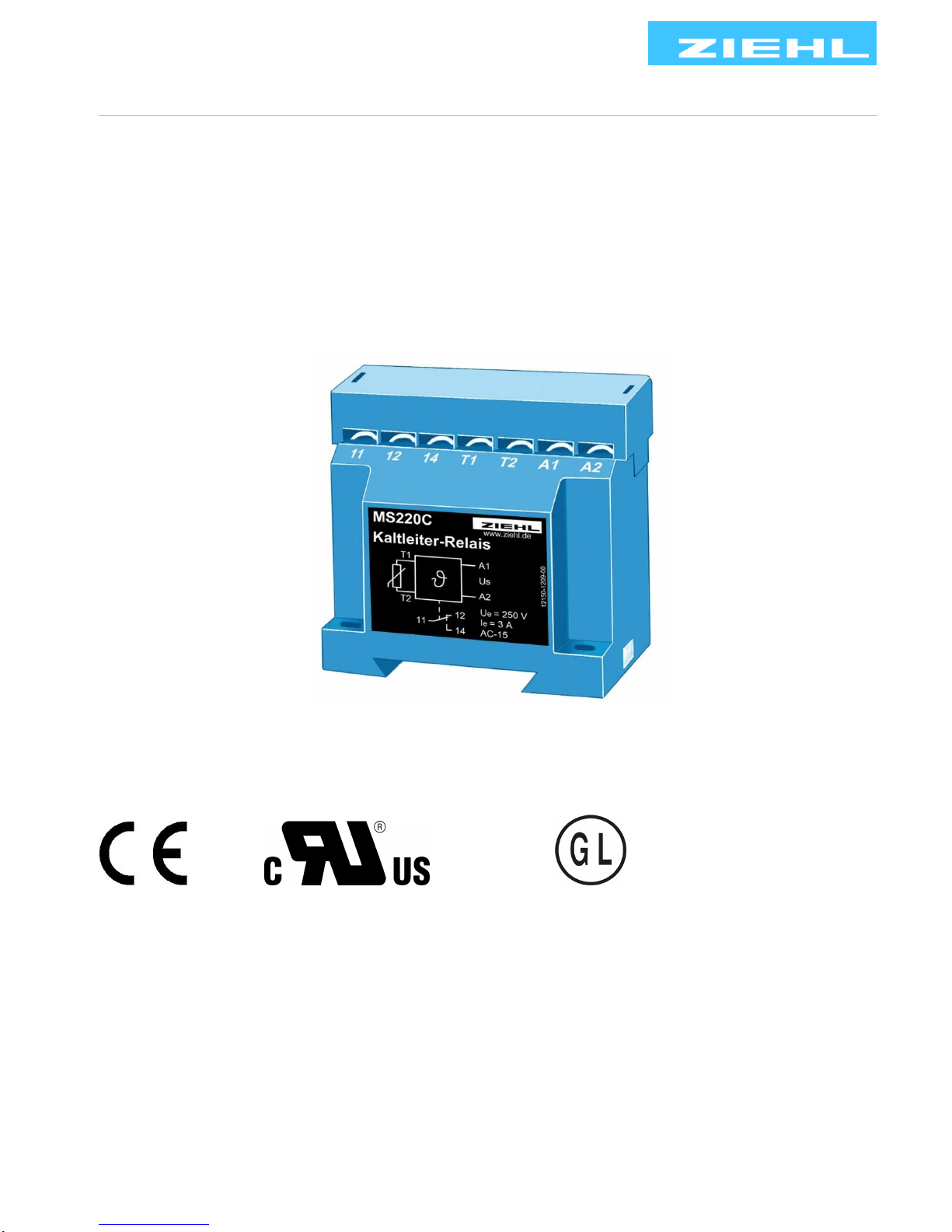
Operating Instructions MS220C
updated: 2017-11-08 Su
MS220C 12150-0703-03 Page 1 / 8 www.ziehl.de
PTC-thermistor relay , TMP tripping device – Power supply AC and AC/DC
E179399
Approvals: marking see type plate on the device
Page 2

MS220C 12150-0703-03 Seite 2 / 8 www.ziehl.de
Table of contents
1 Display and control elements ................................................................................................................ 2
2 Pre-Adjustment ....................................................................................................................................... 2
3 Application and short description ......................................................................................................... 2
4 Summary of functions ............................................................................................................................ 3
5 Connecting diagram: .............................................................................................................................. 3
6 Function diagram ................................................................................................................................... 3
7 Important notes ...................................................................................................................................... 4
8 Installation .............................................................................................................................................. 4
9 Commissioning....................................................................................................................................... 5
10 Trouble shooting ................................ ................................................................ .................................... 5
11 Maintenance and repair .......................................................................................................................... 5
12 Technical data ........................................................................................................................................ 6
13 Form C ..................................................................................................................................................... 8
1 Display and control elements
The MS220C is a built-in device and has no display or operating elements. The status can be signalled by
monitoring the normal closed contact and an external signal lamp.
2 Pre-Adjustment
No settings are necessary on the devices. The tripping temperature is determined solely by the response
temperature of the connected PTC thermistors.
Depending on the number of PTC thermistors the following tripping temperatures and reset temperatures
arise related to TNF (detector operating temperature):
Tripping temperature
Reset temperature
1 PTC thermistor
TNF + 15 K
TNF + 5 K
3 PTC thermistors in series
TNF + 5 K
TNF – 5 K
6 PTC thermistors in series
TNF
TNF – 20 K
3 Application and short description
ZIEHL PTC-resistor relays protect motors, transformers, machines and equipment against thermal overload.
With ZIEHL PTC Sensors MINIKA ® applied they offer best solutions for nominal response temperatures
60°C…180°C.
TMP tripping device is according EN 60947-8 (VDE 0660 part 0302). PTC- thermistor sensors according
DIN 44081 und 44082 (VDE 0660 part 0303) can be connected. PTC- thermistors are suitable for the
installation into windings of electrical machines, bearings and transformers as well as to monitor the
temperature of liquid media, airflow and gases.
Used in conjunction, they provide a effectively and reliable protection in case of
• blocking rotors, heavy starts, counter current operation
• under voltage and phase failure
• increased ambient temperature and hindered cooling
Page 3
MS220C 12150-0703-03 Seite 3 / 8 www.ziehl.de
4 Summary of functions
- 1 PTC-resistor set with up to 6 PTC Sensors in series
- Sensors and relays are exchangeable
- Sensors with fixed nominal response temperature 60...180°C
- Suitable with thermal contacts
- Relay output with change-over contact (co), floating extern
- Snap mounting on standard rails or screw mounting
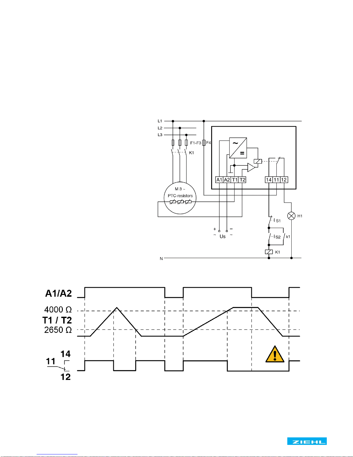
A current monitors continuously the resistance of the sensors. In cold state, the resistance is < 250 Ω per
sensor (sensor circuit < 1,5 kΩ). The relay has picked up and contact 11/14 is closed. The resistance of the
sensor rises rapidly at nominal response temperature NRT. The relay release at a resistance between 2650
Ω < R < 4000 Ω. The relay switches on automatically at a resistance 1650 Ω < R < 2650 Ω.
5 Connecting diagram:
Us = supply voltage
S1 = push-button OFF
S2 = push-button ON
H1 = indicator lamp fault
F1-F4 = fuses
K1 = contactor
6 Function diagram
Caution! Tripping is not stored and is not non-volatile!
The released relay switches on automatically after a voltage dip.
Page 4
MS220C 12150-0703-03 Seite 4 / 8 www.ziehl.de
7 Important notes
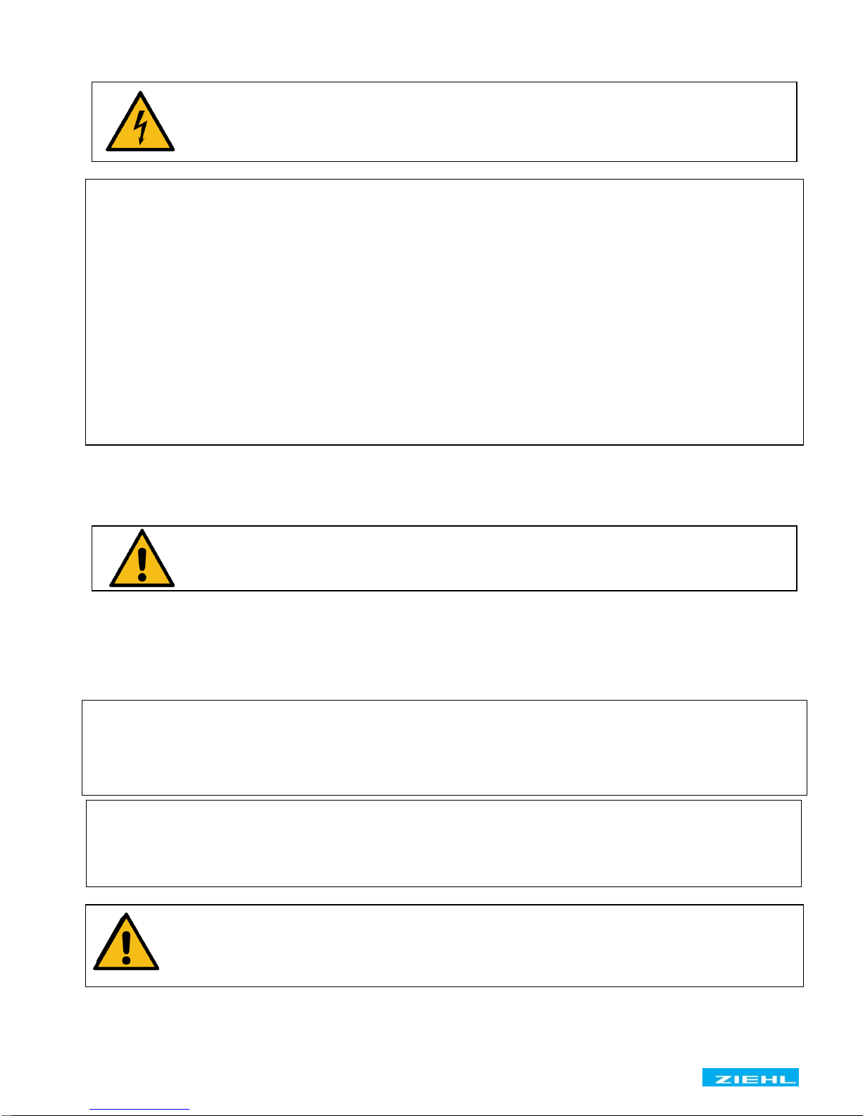
DANGER!
Hazardous voltage!
Will cause death or serious injury. Turn off and lock out
all power supplying this device before working on this device!
To use the equipment flawless and safe, transport and store properly, install and start professionally and
operate as directed.
Only let persons work with the equipment who are familiar with installation, start and use and who have
appropriate qualification corresponding to their function. They must observe the contents of the instructions
manual, the information which are written on the equipment and the relevant security instructions for the
setting up and the use of electrical units.
The equipments are built according to EN60947 and checked and leave the plant according to security in
perfect condition. To keep this condition, observe the security instructions with the headline „Attention“
written in the instructions manual. Ignoring of the security instructions may lead to death, physical injury or
damage of the equipment itself and of other apparatus and equipment.
If, in any case the information in the instructions manual is not sufficient, please contact our company or the responsible representative.
Instead of the industrial norms and regulations written in this instructions manual valid for Europe, you must
observe out of their geographical scope the valid and relevant regulations of the corresponding country.
8 Installation
Attention!
Observe safety rules and standards. Notice safety remarks!
• The device can be mounted on 35 mm rail according EN 60715 or with screws M4 (Option)
• The devices must be installed in an enclosure of international protection class IP 5x or better.
• Housing overall width 35 mm (2 TE)
• Terminals with screw mounting M3 maximum tightening torque 0,8 Nm
When installing the device into the switchgear cabinet, please observe the max. admissible
temperature. Care for both, sufficient clearance to other devices or sources of heat or
enough forced draught. If cooling is made more difficult, e.g. close devices with increased
surface temperature or by handicap of airflow cooling, the permissible ambient temperature
has to be reduced.
The lines of the sensor circuit are to be routed as separate control lines. The use of lines of
the supply cable or other mainstream lines is not permissible. If extreme inductive or
capacitive stray effects are to be expected by parallel cables of the power installation,
shielded control lines should be used.
Attention! TMP tripping relays with supply voltage DC/AC 24 V without
potential separation are intended to use at power supplies according SELV
or PELVwhere protected wiring is used.
!
Page 5

MS220C 12150-0703-03 Seite 5 / 8 www.ziehl.de
9 Commissioning
Attention!
Before switching on make sure that the operational voltage Us of the
Type plate and the mains voltage are the same!
After the supply voltage is switched on and when the thermistors are correctly connected the relay contacts
11,14 close.
The correct function of the tripping device must be checked by resistance simulation at terminals T1 and T2.
This check is also performed after changes to the installation.
Line interruption test: disconnect sensor line at terminal T1 or T2
Temperature test: increase resistance 0 Ω < R < 1500 Ω up to 4000 Ω.
With commissioning and after modification of the plant the sensor resistance must be checked with a suitable
measuring instrument. With a resistance < 50 Ω the sensor circuit is to be examined for short-circuit.
Attention! Check PTC’s only with measuring voltages of < 2.5 V.
10 Trouble shooting
Relay does not pick up. Please check:
• The supply voltage Us at terminals A1 - A2
• The PTC sensors at terminals T1 - T2
• The resistance of a PTC set must be within 0 Ω < R < 1500 Ω. The terminal voltage T1 - T2 is to be
measured < 0,8 V with connected PTC’s.
Relay does not release. Please check:
• With no PTC sensor connected the TMP trip relay must release.
• The voltage at terminals T1-T2 must be > 1 V.
In case of any other malfunction replace the device. Please add a description of the failure and send it back
for repair.
11 Maintenance and repair
The devices are maintenance-free. Only the manufacturer may accomplish repairs. We recommend testing
within the regular maintenance intervals of the plant, where the device is used.
Page 6

MS220C 12150-0703-03 Seite 6 / 8 www.ziehl.de
12 Technical data
Power supply (A1, A2)
Rated supply voltage Us
AC / DC 24 V (no potential separation)
Tolerance Us
AC 20,4…26,4 V DC 20,4…30 V
Power consumption
< 2 VA < 1 W
Rated supply voltage Us
AC 110-120 V, AC 220-240 V
Tolerance Us
0,9 Us…1,1 Us
Rated frequency for AC
50 / 60 Hz
Tolerance of frequency
45 Hz - 65 Hz
Power consumption
2 VA
On-period
100%
Buffer time in case of power failure
max. 20 ms
Input (T1, T2)
PTC-Thermistors acc. DIN 44081 and DIN 44082
Number of PTC Thermistors
Set with 1…6 PTC’s in series
System operating temperature TFS
60 °C … 180 °C
Tolerance TFS
±6 °C
Collective resistance cold thermistor
≤1.65 kΩ
Terminal voltage (PTC thermistor)
≤ 0.8 V at R ≤ 1.5 kΩ, ≥ 1 V at R =
Terminal current (PTC thermistor)
< 0.3 mA
Power consumption
≤ 1 mW
Line capacity max.
0.2 µF
Temperature monitor cut-out-point
≤ 4 kΩ
Temperature monitor reclosing point
≥ 1,65 kΩ
Relay output (11,12,14)
EN 60947-5-1
Contacts
1 change-over contact (co)
Rated operational voltage Ue
250 V
Switching voltage max.
AC 415 V
Switching current .max.
6 A
Conventional free air thermal current Ith
5 A
Making current < 20 ms
30 A
Min. operational current at 12 V
10 mA
Switching power AC-1 max.
1250 VA
Switching power DC-1 max.
120 W at DC 24 V
Rated operational current (Ie)
AC-15
Ie = 3 A
Ue = 250 V
DC-13
Ie = 2 A
Ue = 24 V
DC-13
Ie = 0,2 A
Ue = 240 V
Mechanical contact life
3 x 10⁷ operations
Electrical contact life AC-1
1 x 10⁵ operations at 240 V/ 6 A
Recommended fuse NO
4 A time-lag or miniature circuit-breaker MCB B4
Recommended fuse NC
3,15 A time-lag
Electrical Safety – Testing conditions
EN 60 947-1
Rated insulation voltage Ui
415 V
Rated impulse voltage
4000 V
Overvoltage category
III
Contamination level
2
Transformer
EN 61558-2-6
Test Voltage Input/output
2500 V 50 Hz
EMC - Immunity
EN 61000-6-2
EMC - Emission
EN 61000-6-3
Page 7

MS220C 12150-0703-03 Seite 7 / 8 www.ziehl.de
Ambient conditions
Rated ambient temperature range
-20 °C... +55 °C
Storage (1K4 EN60721-3-1)
-25 °C… +55 °C
Transportation (2K3 EN 60721-3-2)
-25 °C… +70 °C
Alltitude
≤ 2000 m NHN
Mounting position
any
Climatic conditions (3K3 EN60721-3-3)
5-85% rel. F., no condensation
Vibration resistance EN 60068-2-6
2…25 Hz ±1,6 mm 25 ... 150 Hz 5g
Housing
Form C
Dimensions (H x W x D) mm
72 x 33 x 60
Material
PA66
Flammability class
UL 94 V-2
Protection class housing/terminals EN 60529
IP 40/IP20
Mounting EN 60715
35 mm standard rail according or with screws M4
Weight
app. 120 g (with transformer)
app. 80 g (others)
Screw - Terminals
M 3,5
Tightening torque
0.8 Nm (7 lb.in)
Line connection solid wire
2 x 0,5…2,5 mm2 (AWG 20…14)
Stranded wire with insulated ferrules
2 x 0,34 …1,5 mm2 (AWG 20…16)
Insulation strip length min.
8 mm
Subject to technical modifications
You’ll find this and other user manuals in the internet under
www.ziehl.com
ZIEHL industrie – elektronik GmbH + Co KG
Daimlerstr. 13
74523 Schwaebisch Hall
Germany
Fon + 49 791 504-0 [email protected] www.ziehl.de
Page 8
MS220C 12150-0703-03 Seite 8 / 8 www.ziehl.de
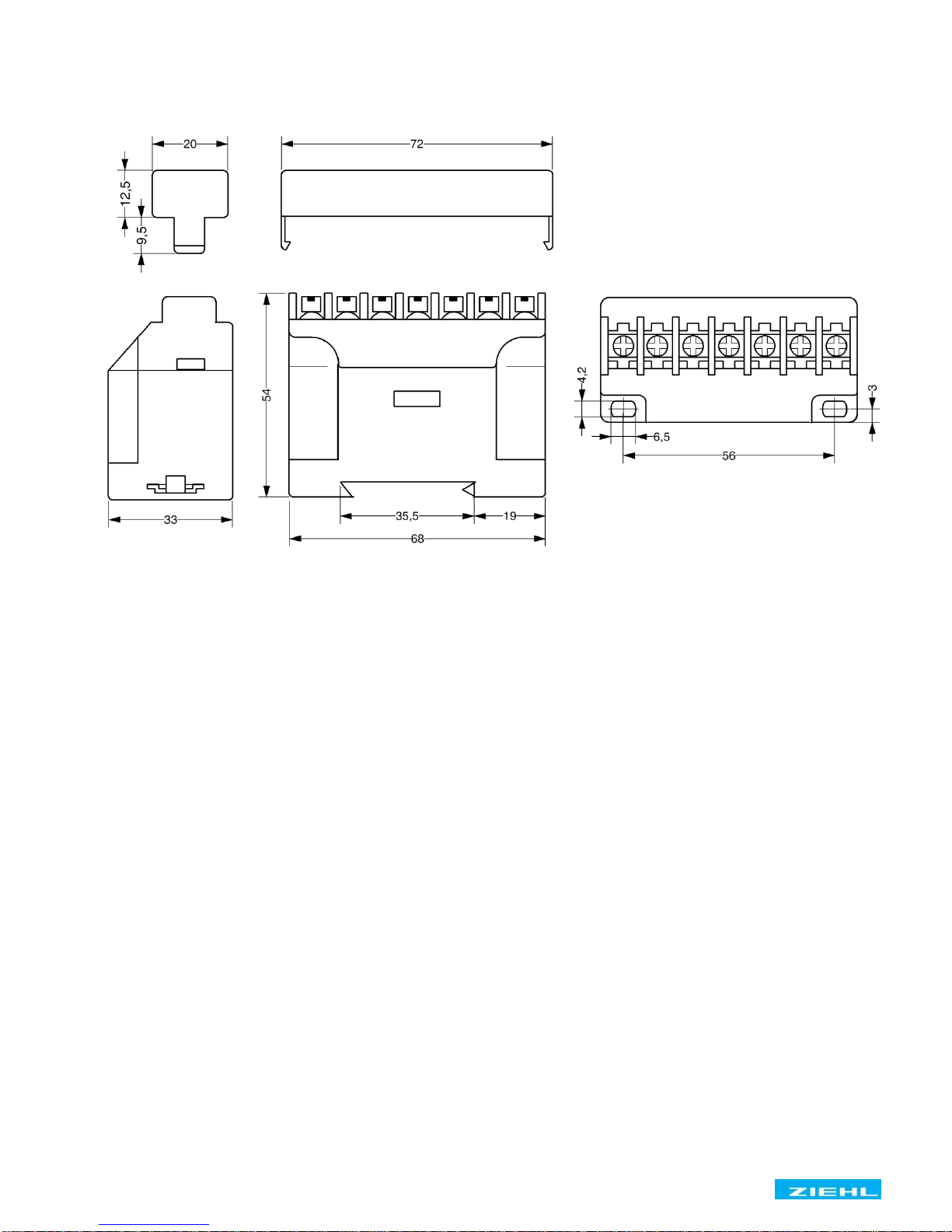
13 Form C
Dimension in mm
 Loading...