

Page 1
¦¸
CAP
V
20A
A
For
30sec.
A
mA
15 min.
every
MAX
A
V
¦¸
F
-+
HOLD
C
F
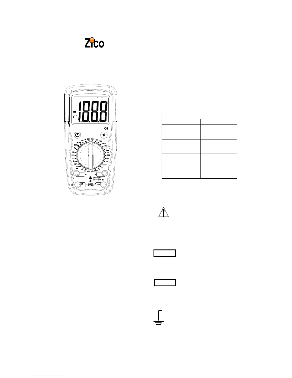
ZI-6550
OPERATING INSTRUCTION
DIGITAL MULTIMETER
www.zicotech.com
SAFETY INFORMATION
The following safety information must be observed to
insure maximum personal safety during the operation
at this meter:
Do not use the meter if the meter or test leads
look damaged, or if you suspect that the meter is
not operating properly.
Never ground yourself when taking electrical
measurements. Do not touch exposed metal pipes,
outlets, fixtures, etc., which might be at ground
potential. Keep your body isolated from ground
by using dry clothing, rubber shoes, rubber mats,
or any approved insulating material.
Turn off power to the circuit under test before
cutting, unsoldering, or breaking the circuit.
Small amounts of current can be dangerous.
Use caution when working above 60V dc or 30V
ac rms. such voltages pose a shock hazard.
When using the probes, keep your fingers behind
the finger guards on the probes.
Measuring voltage which exceeds the limits of
the multimeter may damage the meter and
expose the operator to a shock hazard. Always
recognize the meter voltage limits as stated on
the front of the meter.
Never apply voltage or current to the meter that
exceeds the specified maximum:
SAFETY SYMBOLS
This symbol adjacent to another
symbol, terminal or operating device
indicates that the operator must refer
to an explanation in the Operating
Instructions to avoid personal injury
or damage to the meter.
This WARNING symbol indicates a
potentially hazardous situation, which
if not avoided, could result in death or
serious injury.
This CAUTION symbol indicates a
potentially hazardous situation, which
if not avoided, may result damage to
the product.
This symbol advises the user that the
terminal(s) so marked must not be
connected to a circuit point at which
the voltage with respect to earth
ground exceeds (in this case) 1000
Input Limits
Function
Maximum Input
V DC or V AC
1000V DC, 700V
AC
mA DC/AC
200mA DC/AC
A DC/AC
20A DC/AC (30
seconds max every
15 minutes)
Frequency,
Resistance,
Capacitance, Diode,
Continuity
Temperature
250V DC/AC
WARNING
CAUTION
MAX
Page 2
1
4
5
2
3
¦¸
CAP
V
20A
A
For
30sec.
A
mA
15 min.
every
MAX
A
V
7
8
¦¸
F
-+
6
HOLD
C
F
VAC or VDC.
This symbol adjacent to one or more
terminals identifies them as being
associated with ranges that may, in
normal use, be subjected to
particularly hazardous voltages. For
maximum safety, the meter and its test
leads should not be handled when
these terminals are energized.
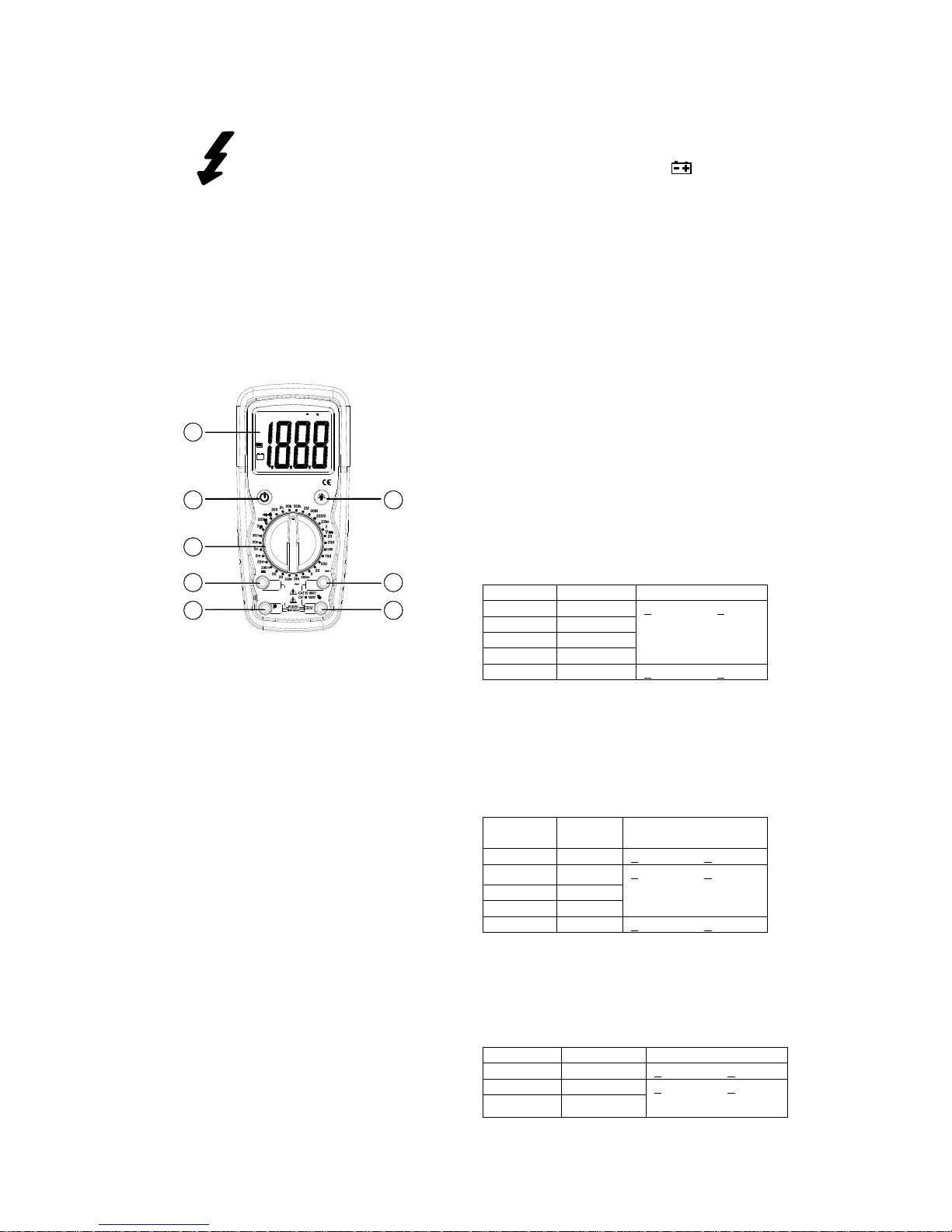
CONTROLS AND JACKS
1. Large 2000 count Liquid Crystal Display
With backlight and HOLD, ℃, ℉, BAT symbolic
signs.
2. Power pushbutton: the power button turns the meter
ON or OFF.
3. Function switch
4. 20A (positive) input jack for 20A DC or
AC measurements.
5. mA input jack for mA DC or AC measurements
6. Backlight pushbutton.
7. V,Ω,CAP, Hz, TEMP. input jack
8. COM (negative) input jack.
SPECIFICATIONS
The instrument complies with: EN61010-1.
Insulation: Class2, Double insulation.
Overvoltage category: CATII - 1000V.
Display: 2000 counts LCD display with function
indication.
Polarity: Automatic, (-) negative polarity indication.
Overrange: “OL” mark indication.
Low battery indication: The “ ” is displayed
when the battery voltage drops below the operating
level.
Auto power off: Meter automatically shuts down
after approx. 10 minutes of inactivity.
Measurement rate: 2 times per second, nominal.
Operating environment: 0 oC to 50 oC (32 oF to 122
o
F) at < 70 % relative humidity.
Storage temperature: -20 oC to 60 oC (-4 oF to 140
o
F) at < 80 % relative humidity.
For inside use, max height: 2000m
Pollution degree: 2
Power: One 9V battery , NEDA 1604, IEC 6F22.
Dimensions: 182 (H) x82 (W) x 55 (D) mm
Weight: Approx.: 360g.
Accuracy is given at 18 oC to 28 oC (65 oF to 83 oF),
less than 70 % RH
DC Voltage
Range
Resolution
Accuracy
200.0mV
0.1mV
+0.5% of rdg + 2 dgts
2.000V
1mV
20.00V
10mV
200.0V
100mV
1000V
1V
+0.8% of rdg + 2 dgts
Input Impedance: 10M.
200mV range Maximum Input: 250V dc or 250V ac
rms.
Maximum Input: 1000V dc or 700V ac rms.
AC Voltage
Range
Resoluti
on
Accuracy
200.0mV
0.1mV
+1.0% of rdg + 5 dgts
2.000V
1mV
+1.0% of rdg + 3 dgts
20.00V
10mV
200.0V
100mV
700V
1V
+1.2% of rdg + 5 dgts
Input Impedance: 10M.
Frequency Range:50 to 400Hz
Maximum Input: 1000V dc or 700V ac rms.
DC Current
Range
Resolution
Accuracy
2.000mA
1uA
+1.0% of rdg + 3 dgts
20.00mA
10uA
+1.5% of rdg + 3 dgts
200.0mA
100uA
Page 3
20.00A
10mA
+2.5% of rdg + 10 dgts
Overload Protection: 0.2A / 250V and 20A / 250V
Fuse.
Maximum Input: 200mA dc or 200mA ac rms on mA
ranges, 20A dc or ac rms on 20A range.
AC Current
Range
Resolution
Accuracy
2.000mA
1uA
+1.2% of rdg + 3 dgts
200.0mA
100uA
+2.0% of rdg + 3 dgts
20.00A
10mA
+3% of rdg + 10 dgts
Overload Protection: 0.2A / 250V and 20A / 250V
Fuse.
Frequency Range: 50 to 400 Hz
Maximum Input: 200mA dc or 200mA ac rms on mA
ranges, 20A dc or ac rms on 20A range.
Resistance
Range
Resolution
Accuracy
200.0
0.1
+1.0% of rdg + 4 dgts
2.000k
1
+1.0% of rdg + 2 dgts
20.00k
10
+1.2% of rdg + 2 dgts
200.0k
100
2.000M
1k
20.00M
10k
+2.0% of rdg + 5 dgts
200.0M
10k
+5.0% of rdg + 10
dgts
Input Protection: 250V dc or 250V ac rms.
Capacitance
Range
Resolu
tion
Accuracy
2.000nF
1pF
+4.0% of rdg+70dgts
20.00nF
10pF
+4.0% of rdg + 3 dgts
200.0nF
0.1nF
+4.0% of rdg + 3 dgts
2.000uF
1nF
200.0uF
0.1uF
≤20uF
+4.0% of rdg + 15
dgts
≥21uF
unspecified
Input Protection: 250V dc or 250V ac rms.
Diode Test
Test current: 1mA typical
Open circuit voltage: 2.8V dc typical
Overload protection: 250V dc or ac rms.
Audible continuity
Audible threshold: Less than50 Test current:
<0.3mA
Overload protection: 250V dc or ac rms.
OPERATION
WARNING: Risk of electrocution.
High-voltage circuits, both AC and DC,
are very dangerous and should be
measured with great care.
If “1” appears in the display during a measurement,
the value exceeds the range you have selected. Change
to a higher range.
NOTE: On some low AC and DC voltage ranges, with the
test leads not connected to a device, the display may show a
random, changing reading. This is normal and is caused by
the high-input sensitivity. The reading will stabilize and give
a proper measurement when connected to a circuit.
BACK LIGHT BUTTON
The BACK LIGHT BUTTON is used to turn the back light on
Only. To extend the battery life, The back light will be turned off
automatically within around 3 seconds
DC VOLTAGE MEASUREMENTS
CAUTION: Do not measure DC voltages if a motor
on the circuit is being switched ON or OFF. Large
voltage surges may occur that can damage the meter.
1. Set the function switch to the V DC position (“mV” will
appear in the display).
2. Insert the black test lead banana plug into the negative
(COM) jack and the red test lead banana plug into the
positive (V) jack.
3. Touch the test probe tips to the circuit under test. Be sure
to observe the correct polarity (red lead to positive, black
lead to negative).
4. Read the voltage in the display. The display will
indicate the proper decimal point and value. If the
polarity is reversed, the display will show (-) minus
before the value.
AC VOLTAGE MEASUREMENTS
WARNING: Risk of Electrocution. The probe tips
may not be long enough to contact the live parts inside
some 240V outlets for appliances because the contacts
are recessed deep in the outlets. As a result, the reading
may show 0 volts when the outlet actually has voltage
on it. Make sure the probe tips are touching the metal
Page 4
contacts inside the outlet before assuming that no
voltage is present.
CAUTION: Do not measure AC voltages if a motor
on the circuit is being switched ON or OFF. Large
voltage surges may occur that can damage the meter.
1. Set the function switch to the V AC position.
2. Insert the black test lead banana plug into the
negative (COM) jack and the red test lead banana
plug into the positive (V) jack.
3. Touch the test probe tips to the circuit under test.
4. Read the voltage in the display. The display will
indicate the proper decimal point, value and
symbol (AC, V, etc.).
DC CURRENT MEASUREMENTS
CAUTION: Do not make current measurements on
the 20A scale for longer than 30 seconds. Exceeding 30
seconds may cause damage to the meter and/or the test
leads.
1. Insert the black test lead banana plug into the negative
(COM) jack.
2. For current measurements up to 200mA DC, set the
function switch to the mA range and insert the red test
lead banana plug into the (mA) jack.
3. For current measurements up to 20A DC, set the
function switch to the A position and insert the red test
lead banana plug into the 20A jack.
4. Remove power from the circuit under test, then open up
the circuit at the point where you wish to measure
current.
5. Touch the black test probe tip to the negative side of the
circuit. Touch the red test probe tip to the positive side of
the circuit.
6. Apply power to the circuit.
9. Read the current in the display. The display will indicate
the proper decimal point, value.
AC CURRENT MEASUREMENTS
WARNING: To avoid electric shock, do not measure
AC current on any circuit whose voltage exceeds 250V
AC.
CAUTION: Do not make current measurements on
the 20A scale for longer than 30 seconds. Exceeding 30
seconds may cause damage to the meter and/or the test
leads.
1. Insert the black test lead banana plug into the negative
(COM) jack.
2. For current measurements up to 200mA AC, set the
function switch to the mA range and insert the red test
lead banana plug into the (mA) jack.
3. For current measurements up to 20A AC, set the function
switch to the A position and insert the red test lead
banana plug into the 20A jack.
4. Remove power from the circuit under test, then open up
the circuit at the point where you wish to measure
current.
5. Touch the black test probe tip to the negative side of the
circuit. And touch the red test probe tip to the positive
side of the circuit.
6. Apply power to the circuit.
7. Read the current in the display. The display will
indicate the proper decimal point, value.
8. RESISTANCE MEASUREMENTS
WARNING: To avoid electric shock, disconnect power
to the unit under test and discharge all capacitors before
taking any resistance measurements. Remove the
batteries and unplug the line cords.
1. Set the function switch to the position.
2. Insert the black test lead banana plug into the negative
(COM) jack and the red test lead banana plug into the
positive jack.
3. Touch the test probe tips across the circuit or part under
test. It is best to disconnect one side of the part under test
so the rest of the circuit will not interfere with the
resistance reading.
4. Read the resistance in the display. The display will indicate
the proper decimal point, value
CONTINUITY CHECK
WARNING: To avoid electric shock, never measure
continuity on circuits or wires that have voltage on
them.
1. Set the function switch to the position.
2. Insert the black lead banana plug into the negative (-)
Page 5
jack (COM) and the red test lead banana plug into the
positive (+) jack ().
3. Touch the test probe tips to the circuit or wire you wish
to check.
4. If the resistance is less than approximately 50, the
audible signal will sound. The display will also show the
actual resistance.
DIODE TEST
WARNING: To avoid electric shock, do not test any
diode that has voltage on it.
1. Set the function switch to position.
3. Insert the black test lead banana plug into the negative (-)
jack (COM) and the red test lead banana plug into the
positive (+) jack ().
4. Touch the test probe tips to the diode or
semiconductor junction you wish to test. Note the meter
reading
5. Reverse the probe polarity by switching probe position.
Note this reading.
6. The diode or junction can be evaluated as follows:
A. If one reading shows a value and the other reading
shows “1”, the diode is good.
B. If both readings show “1”, the device is open.
C. If both readings are very small or 0, the device is
shorted.
NOTE: The value indicated in the display during the diode
check is the forward voltage.
CAPACITANCE MEASUREMENTS
WARNING: To avoid electric shock, disconnect power
to the unit under test and discharge all capacitors before
taking any capacitance measurements. Remove the
batteries and unplug the line cords.
1. Set the function switch to the CAP position.
2. Insert the black test lead banana plug into the negative (-)
jack (COM) and the red test lead banana plug into the
positive (+) jack (CAP).
3. Touch the test leads to the capacitor to be tested.
The display will indicate the proper decimal point,
value
REPLACING THE BATTERY
WARNING: To avoid electric shock, disconnect the test
leads from any source of voltage before removing the
battery door.
1. When the batteries become exhausted or drop below
the operating voltage, “BAT” will appear in the
right-hand side of the LCD display. The battery should
be replaced.
2. Follow instructions for installing battery. See the
Battery Installation section of this manual.
3. Dispose of the old battery properly.
WARNING: To avoid electric shock, do not operate your
meter until the battery door is in place and fastened
securely.
BATTERY INSTALLATION
WARNING: To avoid electric shock, disconnect the
test leads from any source of voltage before
removing the battery door.
1. Disconnect the test leads from the meter.
2. Open the battery door by loosening the screw using a
Phillips head screwdriver.
3. Insert the battery into battery holder, observing the
correct polarity.
4. Put the battery door back in place. Secure with the one
screw.
WARNING: To avoid electric shock, do not operate the
meter until the battery door is in place and fastened
securely.
NOTE: If your meter does not work properly, check the
fuses and battery to make sure that they are still good and
that they are properly inserted.
REPLACING THE FUSES
WARNING: To avoid electric shock, disconnect the test
leads from any source of voltage before removing the
back cover
1. Disconnect the test leads from the meter and any item
under test.
2. Open the back cover by loosening the screw on the back
cover using a Phillips head screwdriver.
3. Remove the old fuse from its holder by gently pulling it
Page 6

out.
3. Install the new fuse into the holder.
4. Always use a fuse of the proper size and value
(0.2A/250V fast blow for the 200mA range, 20A/250V
fast blow for the 20A range).
1. Put the back cover. Insert the screw and tighten it
securely.
WARNING: To avoid electric shock, do not operate your
meter until the fuse door is in place and fastened securely.
 Loading...