

TYCHO 254

WARNINGS
•Do not use telescope or finderscope to look at the sun without
an appropriate solar filter.
•Make sure no screws are loose before using telescope.
•Do not drop, shake, or throw your telescope as doing so may
damage the telescope or people around you.
•Objects in telescope may be farther away than they appear.
•Eyepieces intended for external use only.
•Don’t worry, be happy...
INTRODUCTION
Zhumell telescopes are precision astronomical instruments designed to be easy to use and versatile in their application. As with
any telescope, Zhumell telescopes require some technical knowledge of stellar movement and optical properties. We have tried to
provide the basics of telescope use and astronomical viewing in
this manual. If, after reading through this manual, you still have
questions regarding the setup and use of your telescope, please
feel free to contact us at info@zhumell.com or at (800)922-
2063. Our customer service representatives will be able to help
address any problems you are having with your Zhumell telescope. We also have more information available on our website
at www.zhumell.com. Please let us know about your experiences
with your Zhumell telescope. We would like to hear your feedback and see your astrophotographs. Enjoy your Zhumell.
SPECIFICATIONS
OPTICAL TUBE ASSEMBLY
Objective (mm) 254
Focal Length (mm) 1600
Highest Useful Magnification 600x
Resolving Power 0.46
Limiting Magnitude (Visual) 14.52
Limiting Magnitude (Photographic) 12.52
Focal Ratio F/6.3
Eyepiece Format 1.25”
Finder Scope 8x50
Mount Type EQ5 Equitorial
MOUNT
Materials Aluminum
R.A. Adjustment Manual Worm Gear
Type Reflector
Dec. Adjustment Manual Worm Gear
Clock Drive Axis R.A. and Dec.
Clock Drive Power 4 - D-cell Batteries
INCLUDED ITEMS
•Optical Tube Assembly
•8x50 Finderscope
•EQ5 Equitorial Mount
•Adjustable Speed Clock Drive with Hand Controller
•R.A. and Dec. Adjustment Knobs
•Counterweight (2)
•Aluminum Tripod
•Accessory Tray
•6.5mm and 20mm Plossl Eyepieces
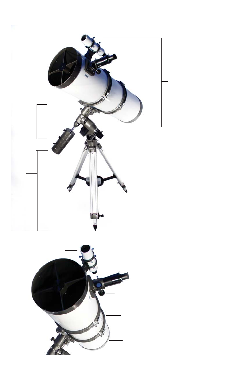
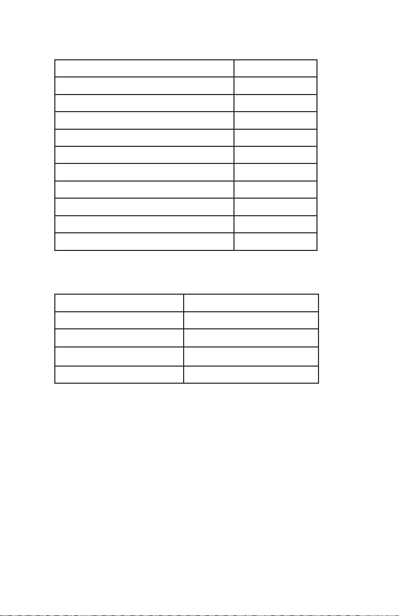
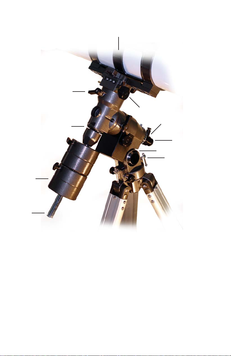
TELE SCOPE LEGEND
2
1
5
3
1. Tripod
2. Mount Assembly
3. Optical Tube Assembly
4. Eyepiece
5. Finderscope
6. Optical Tube Mounting Belt
7. Focuser
8. Primary Mirror
9. Dec. Adjustment Knob
10. Dec. Axis Release
11. Declination Scale
12. Hour Circle (R.A. Scale)
13. Polar Alignment Scope
4
14. Latitude Scale
15. Latitude Adjustment
16. Counterweight
17. Counterweight Shaft
7
6
8
6
10
9
11
16
17
12
13
14
15
CARE OF YOU R TELE SCOPE
A telescope is carefully aligned during construction and great care should
be taken to maintain this alignment over the life of the telescope. Cleaning
should be done as little as possible and then only with a mild soap solution
and soft, lint-free cloth. Do not rub elements when cleaning. Blot optical
components gently and allow telescope to air dry. Store telescope in box
when not in use. Do not use alcohol or solvents to clean any parts of the
telescope. Do not remove optical elements from telescope as doing so may
affect the alignment of optical components when reassembled. If telescope
needs realignment, contact Zhumell or another professional.
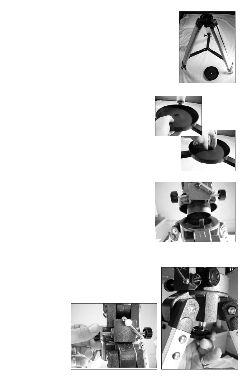
TELE SCOPE ASSEMBL Y
1. Extend tripod legs to comfortable working
height and tighten wingnuts to ensure stability. Separate tripod legs and ensure that the
legs are extended to equal heights. The top of
the tripod should be level to ensure stability
when mounting telescope.
2. Remove accessory tray mounting screw at
the center of tripod leg crossbracce. Set accessory tray on crossbrace, lining us the center
hole of the accessory tray with the raised fitting at the center of crossbraces. Reinsert and
tighten mounting screw.
3. Locate the mount alignment prong extending up from the north leg of the tripod (labelled with an N above the leg). Also locate
the mount rotational stabilization thumbscrews
below the front latitude adjustment screw.
4. Remove the mount base screw. Loosen the
mount rotational stabilization thumbscrews
enough to allow the alignment prong to be
inserted between the bases of the screws. Set
the mount on the top of the tripod so that the
tripod alignment prong is lined up between
the mount rotational stabilization screws.
Tighten rotational stabilization screws so that
the fron mount extrusion is centered over the
north tripod leg. Isert the mount base screw
through the hole in the tripod platform and
hand tighten.
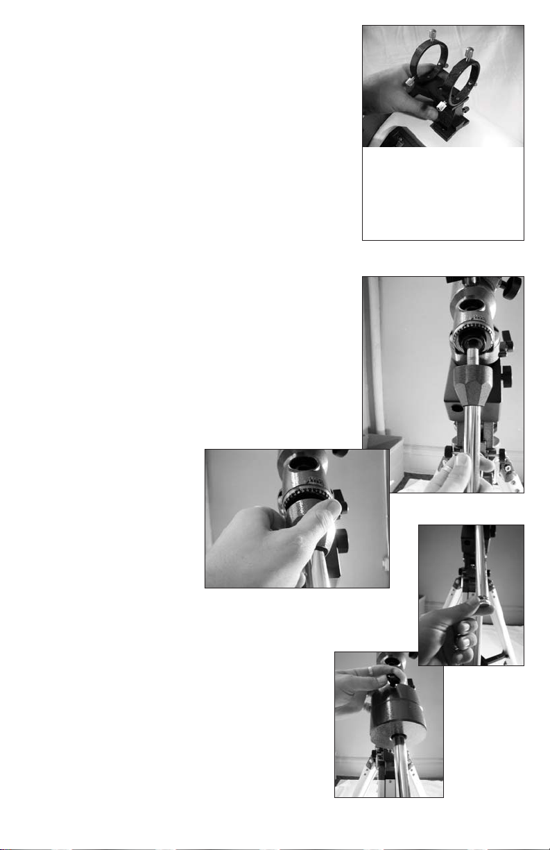
5. Loosen R.A. and Dec. axes by turning axis
release levers 180°. Position mount so that
Dec. axis is at 0° and R.A. Axis is at 0, then
re-tighten the axis release levers. The mount
should now vertically level. With the mount in
this vertical position, find the counter-weight
shaft socket located at the end of the Dec. axis
above the north leg of the tripod.
6. Holding the counterweight shaft, turn the
Dec. axis cap attached to the shaft clockwise
(looking at the large end of the cap) until it
stops. Insert the shaft into the counter-weight
shaft socket and screw the shaft into the socket
unti secure. To eliminate the gap between the
Dec. axis cap and the Dec. axis of the mount,
turn cap (without turning the counterweight
shaft) until it is snug with the end of the Dec.
axis.
7. Remove screw located at the end of the
counterweight shaft. Loosen the thumbscrews
on the counterweights until shaft opening in
the counterwiegt is completely unobstructed.
With the thumbscrew pointing down, slide
the counterweight up the counterweight shaft
and tighten counterweight thumbscrew until
snug. Repeat for each counterweight. Replace
the end screw of the counterweight shaft and
tighten until snug.
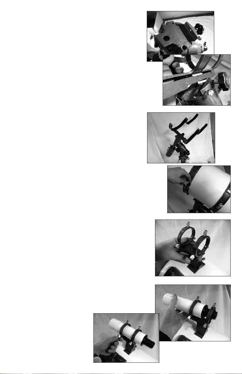
8. Loosen the two thumbscrews located at the
top of the mount to allow the optical tube
mounting rings to be inserted in the groove.
Place the optical tube mounting rings into the
groove and tighten the large thumbcrew until
the end of the screw is snug against the optical
tube mounting ring base. Tighten the small
screw against the optical tube mounting ring
base to add stability to the moounting rings.
9. Open optical tube mounting rings by
loosening thumbscrews on side of mounting rings. Lift the optical tube assembly by
the attached handle near the focuser and
set it into the optical tube mounting rings,
guiding it with your other hand. Close the
optical tube mounting rings and retighten the
thumbscrews on the mounting rings to secure
optical tube assembly.
10. Remove nuts from finderscope mounting bolts near the focuser on the optical tube
assembly. Slide finderscope mount over the
bolts and replace nuts, turning them until they
are snug against the finderscope mount.
11. Loosen finderscope mounting screws
until finderscope can be easily slid into the
mount. Slide finderscope into the mount and
retighten mounting screws so that finderscope
is approximately aligned with the telescope.
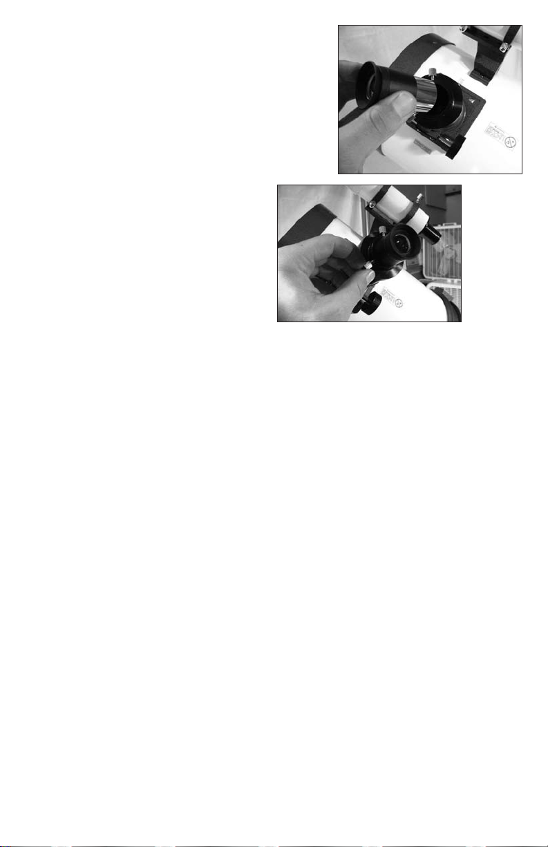
12. To use a 1.25“ eyepiece, loosen eyepiece
receptacle thumbscrew at end of focuser.
Remove dustcover from eyepiece receptacle.
Insert chromed end of eyepiece into the eyepiece receptacle. Re-tighten eyepiece receptacle thumbscrew to secure eyepiece.
13. Enjoy your telescope.
ASSEMBL Y NOTES
In order to avoid visible vibration when viewing at high magnification,
adjust the counterweight position on the counterweight shaft to offset the
weight of the optical tube assembly and balance the telescope.
When placing the optical tube assembly into the mounting rings, center the
rings along the length of the optical tube assembly. Centering the rings along
the length of the optical tube assembly will help to keep the telescope balanced and increase overall stability of the telescope.

CLOCK DRIVE CONTROLS
Direction and Speed
Controls
Hemisphere and Power
Setting
Battery Pack Connection
Motor Connection Cord
CONNECTING THE HAND CONTROLLER
To use the clock drive, connect the havd controller by plugging the Motor
Connection Cord into the receptacle at the base of the plastic housing on the
R.A. drive of the mount. Place 4 D-cell batteries into the battery pack and
plug the power cord from the battery pack into the Battery Pack Connection
receptacle in on the hand controller. To activate the hand controller, simply
switch the hemisphere setting to the appropriate setting and press the desired
speed and direction button.

USING THE CLOCK DRIVE
The clock drive included with your telescope is designed to track the movement of stars. It will help keep stars in your field of view during long periods
of viewing as long as the telescope is properly polar aligned and the clock
drive is properly used. Do not be alarmed if you turn on the clock drive and
do not see the telescope moving. Stars appear to move very slowly and the
telescope may not apear to move over a short period of time. To see if your
clock drive is working, aim the telescope at a stationary terrestrial object and
engage the clock drive. Let the clock drive run for 10 to 15 minutes. If the
object you had originally aimed the telescope at appears to have moved when
looking through the eyepiece of the telescope, the clock drive is working.
LOCK DRIVE SETTINGS
C
The clock drive features two sets of controls which can be used to control
the motion of the telescope The power switch doubles as the hemisphere setting. If you are using the telescope in the Northern Hemisphere, the switch
should be set to the upper position, in the Southern Hemisphere, the switch
should be set to the lower position. The speed setting should be adjusted
while viewing to help keep stars centered in the field of view. You may have
to increase or decrease your speed setting if stars appear to drift in your field
of view. You will need to adjust the clock drive based on what you are looking at while viewing. As a general rule, the farther away from the celestial
pole (closer to the horizon) an object that you are viewing is, the faster it will
appear to move and the faster the clock drive speed will need to be set.
MANUAL ADJUSTMENT WITH CLOCK DRIVE
The clock drive included with your telescope should only be used to follow
stars. When you would like to point your telescope at a different celestial
object, you must disengage the clock drive. By loosening the thumbscrew
on the clock drive R.A. axis, you will disengage the clock drive, protecting
the clock drive and making manual adjustment easier. Manually adjusting the
R.A. axis with the clock drive engaged may cause the gearing in the clock
drive to strip, compromising the operation of the clock drive. When you
would like to reengage the clock drive, simply tighten the thumbscrew and
use the clock drive hand controller to begin tracking stars.

SOME NOTES ON V IEWING
Never look at the sun without using a solar filter. When using a solar filter,
do not remove the full lenscap, view only through the small opening in the
lenscap. Looking at the sun without proper use of a solar filter can cause
permanent eye damage.
When looking through the telescope, the image will appear to be upsidedown and inverted. This results from the optical system design and is normal. This can be corrected by using a diagonal mirror when viewing.
Use of the fi nderscope will help locate celestial objects more quickly as the
fi nderscope has a much wider fi eld of view than the telescope. When viewing, start with the lowest power magnifi cation and work up to the desired
magnifi caiton as this will simplify focusing greatly.
When viewing faint deep sky objects, images will not show color. The human eye is not able to distinguish the differences in color found in such dim
images. The lack of color is due to human anatomy, not any limitations of
telescope construction.
FINDE RSCOPE ALIGNME NT
1. Insert the lowest power eyepiece into the eyepiece adapter. Focus eyepiece
to view an easily recognizable distant object (car license plate, sign, table,
etc.).
2. Look through finderscope being careful not to move the telescope in any
way. Adjust finderscope focus by turning the eyepiece of the finderscope
back and forth until image is in focus. Check to see if the object viewed
through the eyepiece lines up at the center of the finderscope crosshairs. If
not, then your finderscope needs to be realigned.
3. To align finderscope, loosen the thumbscrews which secure the finderscope slightly. Gently move finderscope to center crosshairs on object.
Tighten thumbscrews to secure finderscope in new position. This may take
some time, but will make finding astronomical objects much easier when
using your telescope.

B E GINNING OB SE RV ATION
For beginning observation, the moon is one of the easiest and most enjoyable objects to view. You can acquaint yourself with the movements of the
telescope by simply pointing the telescope at the moon and using the various
adjustments to move the telescope.
To point the telescope at the moon, loosen the R.A. and Dec. clamps (the
thumbscrews located nearest the Hour Circle and Declination Circle on the
mount), then gently move the optical tube assembly until it points at the
moon. Retighten the R.A. and Dec. clamps before viewing.
While viewing, use the R.A. and Dec. adjustment cables to move the telescope. If a motor drive is attached to the telescope, use the hand conroller
for the motor drive instead of the manual controls to move the telescope. The
adjustment cables feature stops which allow a limited degree of adjustment.
To move past a stop, loosen the clamp for the axis you would like to move
and rotate the optical tube assembly past the stop. Be sure to retighten clamps
before viewing to provide a steady image.
If you notice resistance while moving the optical tube assembly, try adjusting
the counterweight position up or down to properly balance the telescope.
The optical tube assembly should move very easily. Do not force the optical
tube assembly, as you may cause damage to the telescope.
INTERMED IATE OB SERV ATION
Once you are familiar with the basic movements and adjustments of the telescope, expand your exploration to other easy to find objects. Venus is one of
the easiest to find planets as it is one of the brightest objects in the night sky.
Local newspapers and planetariums are excellent resources for finding what
planets should be visible in your area on any given night. Other resources
are mentioned at the end of this manual.
To find a planet, look around the sky to locate the planet with your naked
eye first. Once you have located a planet, point the telescope at the planet.
Center the planet in the finderscope by using the crosshairs. Once the planet
is lined up in the finderscope, view the planet through the telescope using
the lowest power (longest focal length) eyepiece. You may need to make
slight adjustments to your aiming of the telescope and you will need to focus
your eyepiece to properly view the planet.
For a closer look at the planet, replace the low powered eyepiec with a higher
powered one and refocus the telescope.

ADV ANCED OB SE RV ATION
STAR CHARTS AND SETTING CIRCLE S
Star charts and setting circles will allow you to find the location of
any known celestial objects viewable by your telescope. By using the
measurements listed on the mount and the coordinates provided in a
star chart, you will be able to find stars, planets, nebulae, and galaxies
for exploration with your telescope. In order to ensure that you can
use the declination and right ascension coordinate system, you will
need to first polar align your telescope for your viewing location.
B EF ORE GE TTING STARTED
Before you begin aligning your telescope, look at the mount and
familiarize yourself with the various scales used in aligning your
scope. The topmost scale on the mount is the declination scale,
which shows the declination angle (between 0 and 90 each way) of
what you are viewing. Slightly below the declination scale is the hour
circle, which shows the right ascension (from 0 to 24 hours) of what
you are viewing. The bottommost scale, located just above the base
of the mount, is the latitude scale which shows latitude measurements
from 0 to 90 degrees. In order to ensure that your measurements are
correct when aligning your telescope, it is important to make sure
that the base of your mount is level. If the base of the mount is not
level, your measurements will be off and aligning will be much more
difficult.
P OLAR AL IGNME NT OF YOU R TELE SCOPE
Polar alignment of your telescope uses easy to find stars to help you
find the center of the celestial sphere. Before aligning your telescope,
you must familiarize yourself with some of the major constellations
in the night sky. For viewing in the Northern Hemisphere, knowing
the locations of Polaris (the North Star) and the constellations Ursa
Major (the Big Dipper) and Cassiopeia (the Queen) will allow you
to properly align your telescope. In the Southern Hemisphere, you
will need to use a star chart to find stars near the meridian and the celestial equator so that you can use the star-drift method to polar align
your telescope. Both Northern and Southern Hemisphere alignment
are described here.

NORTHERN HEM ISP HE RE P OLAR AL IGNME NT
1. To align your telescope in the
Northern Hemisphere, first find the
location of Polaris in the night sky.
You can easily find polaris by using
the Big Dipper to point” at Polaris.
The two stars which make up the
edge of the dipper in the Big Dipper will roughly point” at Polaris.
You can also use the star at the end
of the handle of the Big Dipper and
the star on the edge of the shallower end of Cassiopeia to draw a
line through Polaris. The illustration
shows this.
2. Loosen the declination axis by turning the declination release lever. Turn
the optical tube assembly so that the arrow on the declination scale points at
0. Once the arrow points at 0, the optical tube assembly will be pointed 90
from the polar axis and you will be able to use the polar alignment scope.
3. Remove the lenscaps on the polar alignment scope. The objective of the
polar alignment scope should be directly above the north leg of the tripod
(labelled with an N ). Turn the telescope, tripod and all, so that the front of
the mount faces north. You can use a compass to find magnetic north and
then line up with Polaris (celestial north) or line up the front of the telescope in line with Polaris by imagining a straight line running from Polaris
down to the horizon.
4. Loosen the latitude adjustment screws. As you loosen the screws, you will
notice the number on the latitude scale change. Adjust the latitude scale until
Polaris is in the center of the polar alignment scope. Check that Polaris is
in the center of the telescope’s field of view by swinging the telescope tube
to 90 on the Dec. axis and looking through the focused eyepiece of the
telescope. The number on the latitude scale should match the latitude of your
viewing location. If there is a difference between the latitude of your viewing
location and the number shown on the latitude scale, check to make sure that

SOUTHERN HEMISPHERE & STAR DRIFT POLAR ALIGNMENT
Polar alignment in the Southern Hemisphere is more difficult that in the
Northern Hemisphere because there is no corresponding pole star to use
for alignment in the Southern Hemisphere. Polar aligning in the Southern
Hemishpere is a two part process because of this. A rough alignment must
first be made based on your viewing location. Then, a star drift alignment
should be made to fine tune your alignment. Star drift alignment is also more
accurate than the other methods described here and will be necessary for
long-exposure astrophotography.
R
OUGH ALIGNMENT
Begin by roughly aligning your telescope to the pole by using the mount’s
latitude scale. Set the declination scale to 0 to align the optical tube asssembly with the mount’s polar axis. Check the latitude of your viewing location
and set the latitude scale to the same number. For example, if you were viewing from Sydney, Australia, you would point your telescope due south and
set your latitude adjustment to 34, since Sydney lies at 34S latitude. this will
point you roughly at the southern celestial pole.
STAR DRIFT ALIGNMENT WITH A MOTOR DRIVE
Star Drift alignment is more precise than polar star alignment, but may also
prove to be more difficult to those not used to aligning a telescope. Once you
polar align using the star drift method a few times, it becomes easier, but the
first few times may take a considerable amount of time. For general viewing
uses, the rough alignment described above may prove to be sufficient. The
alignment procedure described below can be used to acheive more accurate
alignment when needed. The alignment is described using a standard eyepiece without an erecting prism or image diagonal.
1. Having already roughly aligned your telescope, loosen the declination
clamp and swivel telescope until scale reads 90, then retighten clamp.
Loosen the right ascension clamp and rotate telescope so that it points 6
hours away from the celestial pole and retighten clamp. The R.A. and Dec.
adjustment cables may need to be temporarily removed in order to swivel
the telescope freely. The telescope should now be pointing roughly where
the meridian and celestial equator intersect.

2. Find a bright star in the viewfinder of your telescope and use the R.A. and
Dec. adjustment cables to center it in the crosshairs. Work up to your most
powerful eyepiece, centering the star in the viewfinder each time you replace
the eyepiece.
3. Engage the clock drive by tightening the thumbscrew which connects it to
the R.A. axis of the mount. Turn on the clock drive, ensuring that it is set to
the correct hemisphere setting. Let the clock drive run for about 5 minutes.
4. Look into the eyepiece after the clock drive has run for about 5 minutes
to see which direction the star has drifted. If the star has drifted to the south
(north in the Northern Hemisphere) in the eyepiece, the mount is pointed
too far to the west. If the star has drifted to the north (south in the North-
ern Hemisphere), the mount is pointing too far to the east. To correct this,
adjust the rotational stabilization screws and center the star in the eyepiece.
Any drifting east or west in the eyepiece is a result of your clock drive speed
setting and can be corrected by adjusting the clock drive speed.
5. Unengage the clock drive. Loosen the right ascension clamp and rotate
the telescope back 6 hours (opposite the direction you rotated it in step 1).
Find a bright star in the viewfinder and center the star in the viewfinder.
Center this star in the highest power eyepiece as you did with the previous
star. Reengage the clock drive and turn it on, letting it run for another five
minutes.
6. Check to see which way this new star has drifted. If the star has drifted to
the north (south in the Northern Hemisphere) in the eyepiece, the mount
latitude setting is too low. If the star drifts to the south (north in the Northern
Hemisphere) in the eyepiece, the mount latitude setting is too high. Adjust
the latitude setting until the star is centered in the field of view. Again, any
drifting east or west in the eyepiece is a result of your clock drive speed setting and can be corrected by adjusting the clock drive speed.
7. Repeat this process as needed until you are satisfied with the alignment
of the telescope. The more closely polar aligned your telescope is, the more
accurate it will track stars.

P OL AR ALIGNME NT U SING THE FINDE RSCOPE
Another method of alignment will work better for aligning your telescope
without the use of a motor drive. The finderscope alignment uses your
finderscope to align your mount to the celestial pole. As you become more
familiar with telescope alignment, you may discover that you prefer one
method over another. The important part of alignment is matching the polar
axis of the mount with the celestial pole and whichever method allows you
to achieve the most accurate alignment is the best one to use.
1. Having already roughly aligned your telescope, loosen the declination
clamp and swivel telescope until Dec. scale reads 90, then retighten clamp.
Loosen the right ascension clamp and rotate telescope so that the finderscope is on the side of the telescope. Look through the finderscope and
center polaris in the finderscope by fine tuning the latitude adjustment and
mount angle by using the latitude adjustment screws and rotational stabilization screws.
2. While looking through the finderscope, slowly rotate the telescope 180
around the polar axis (12 hours in Right Ascension) until the finder is on
the opposite side of the telescope. If the optical axis of the finder is parallel
to the polar axis of the mount, then Polaris will not have moved in relation
to the finderscope’s crosshairs. If, on the other hand, Polaris has moved off
of the crosshairs, then the finderscope will need to be aligned with the polar
axis of the mount. If this is the case, you will notice that Polaris will move in
a semi-circle around the point where the polar axis is pointing. Take notice
how far and in what direction Polaris has moved.
3. Using the screws on the finder bracket, make adjustments to the finderscope and move the cross hairs halfway towards Polaris’ current position.
Once this is done, adjust the mount itself as in the last step so that Polaris
is once again centered in the cross hairs. Wile looking through the finderscope, rotate the telescope back 180 along the R.A. axis to check the finderscope alignment.
4. With each successive adjustment the distance that Polaris moves away
from center will decrease. Repeat steps 2 and 3 until Polaris remains centered on the crosshairs. Once no movement of Polaris in relation to the
crosshairs can be detected, the finderscope is aligned with the polar axis of
the mount.

The finderscope is now properly aligned with the polar axis of your mount
and the mount is aligned to Polaris. The actual North celestial pole lies
about 3/4 away from Polaris toward Alkaid, the last star in the Big Dipper.
To acheive accurate polar alignment, the polar axis of the telescope must
now be lined up with the north celestial pole.
1. While looking through the finderscope (with Polaris still centered in the
cross hairs) adjust the mount with the latitude and rotational adjustment
screws until Polaris moves toward Alkaid. How far to move Polaris will depend on the field of view of the finderscope. If using a finderscope with a
6 field of view, Polaris should be offset approximately 1/3 of the way from
center to edge in the finder’s view (i.e. half of the field of view, from center
to edge, equals 3 and 1/3 of that equals 1 ). This calculation can be approximated for any finderscope with a known field of view.
2. Loosen the R.A. and Dec. axis clamps and aim the telescope at a star near
the celestial equator with known right ascension. Be careful not to move
the mount base or tripod while moving the optical tube. Retighten the axis
clamps.
3. Loosen the R.A. scale tumbscrew and turn the R.A. scale so that the
scale reading matches the right ascension of the star you are centered on.
Retighten the R.A. scale thumbscrew.
4. Using the R.A. and Dec. axis adjustments, turn the telescope so that the
R.A. scale reads 2h30m and the Dec. scale reads 89 1/4. Polaris should
now be centered in the finderscope’s crosshairs. If Polaris is not centered in
the crosshairs, adjust the mount using the latitude and rotational adjustment
screws until Polaris is centered in the crosshairs of the finderscope. Your
mount is now polar aligned.

FIND ING CELE STIAL OBJE CTS
Once your telescope is polar aligned, you must set the hour circle in order to
use the measurements listed on the mount to find celestial objects. Once the
hour circle is properly set, you will be able to use the coordinates listed on
star charts to find objects for viewing in the night sky. Setting the hour circle
will require that you recognize and be able to find a star other than the ones
used for alignment of the telescope.
S
ETTING THE HOU R CIRCLE
To set the hour circle, use a star which you are able to easily identify and
have the coordinates for. In the Northern Hemisphere, Dubhe is a recognizable star which can be used for this. Dubhe is the pointer star in the Big Dipper closest to Polaris and lies at 5842’ Dec., 11h23m R.A.. In the Southern
Hemisphere, Acrux is an easy to find star for setting the hour circle. Acrux is
the closest star to the southern celestial pole in the Southern Cross and lies
at -6315’ Dec., 12h33m R.A..
1. Loosen the declination clamp and rotate the telescope to the nearest degree of declination to the star you will be viewing (58 for Dubhe, -63 for
Acrux). Retighten the clamp to lock the declination in place.
2. Loosen the right ascension clamp and rotate the telescope on the R.A.
axis until the star you are using to set the hour circle is near the center of the
finderscope. Retighten the clamp to lock in the R.A. axis.
3. Center the star in the eyepiece using the R.A. and Dec. adjustment cables.
Once it is centered, turn the hour circle until the arrow points at the appropriate measurement for the star you are looking at (11h23m for Dubhe,
12h33m for Acrux). This sets the hour circle to the appropriate setting for
your viewing location and time.
U
SING SETTING CIRCLE S
With the telescope polar aligned and the hour circle set, you can find celestial objects using star charts available in books or on the web. A star chart
will normally consist of a map and an ephemeris. The ephemeris will tell
you the celestial coordinates of an object. By using the hour circle and the
declination circle, you can point your telescope at the objects you see on
the star chart quickly and easily. You will probably need to fine tune your
aiming with the adjustment cables when you view a new star, but the use of
celestial coordinates will make finding the objects you would like to look at
considerably easier.

ASTRONOM Y F OMUL AE
Magnification
To determine the magnification of a telescope and eyepiece combination, divide the telescope focal length be the eyepiece focal length.
Magnification (x) = Telescope Focal Length (mm)/Eyepiece Focal Length (mm)
Ex: 20mm Eyepiece with a 70x900mm telescope.
Magnification = 900mm/20mm
Magnification = 45x
Focal Ratio
To determine the focal ratio of a telescope, divide the focal length of
the telescope by the aperture.
Focal Ratio (F/x)= Telescope Focal Length (mm)/Aperture (mm)
Ex: Focal Ratio of a 70x900mm telescope.
Focal Ratio (F/x)= 900mm/70mm
Focal Ratio (F/x)= F/12.8
Limiting Magnitude
To determine the limiting magnitude of a telescope, use the aperture in
the following formula for an approximation.
Limiting Magnitude = 7.5 + 5LOG(Aperture in cm)
Ex: Limiting Magnitude of a 114x1000mm telescope.
Limiting Magnitude = 7.5 + 5LOG(11.4cm)
Limiting Magnitude = 7.5 + (5 x 1.057)
Limiting Magnitude = 12.785
Resolving Power
To determine the resolving power of a telescope under ideal conditions,
divide the aperture into 4.56.
Resolving Power = 4.56/Aperture (in.)
Ex: Resolving Power of a 114x1000mm telescope.
Aperture (in.) = 114mm/25.4 = 4.49
Resolving Power = 4.56/4.49in.
Resolving Power = 1.02

ASTRONOM Y TE RM INOLOGY
DECLINATION (DEC.) - The astronomical equivalent of latitude. Declination describes the
angle of a celestial object above or below the celestial equator. The sky over the northern
hemisphere has a positive declination. The sky over the Southern hemisphere has a negative
declination. For example, Polaris (the N orth Star) which lies nearly directly over the North
Pole, has a declination value of 90.
RIGHT ASCEN SION (R.A.) - The astronomical equivalent of longitude. Right Ascension measures the degree of distance of a star to the east of where the ecliptic crosses the celestial
equator. R.A. is measured in hours, minutes, and seconds as opposed to degrees. As oposed
to the term meridian which is used in referring to lines of longitude, right ascension is
referred to as hour circles. There are 24 hour circles of right ascension which run from the
north to south celestial poles.
CELESTIAL EQUATOR - The celestial equator is the line of declination which lies directly above
the Earth’s equator. The celestial equator lies halfway between the north and south celestial
poles and serves as the 0 point in measuring declination.
ECLIPTIC - The ecliptic is the apparent path of the sun through the sky over the course of the
year. Since we view the sun from different angles throughout the year, it appears to move
in relation to other stars. The vernal (spring) and autumnal (fall) equinoxes lie at the points
where the ecliptic intersects the celestial equator. The vernal equinox is where right ascension
is at 0 h (hours). The autumnal equinox can be found at 12 h R.A..
ZEN ITH - The zenith is the point in the celestial sphere directly above your head. The zenith
varies depending upon your location. In general, the declination point of your zenith is
equal to the latitude at which you are standing on Earth.
EPHEMERIS - The ephemeris of a planet or the sun or the moon is a table giving the coordinates of the object at regular intervals of time. The coordinates will be listed using declination and right ascension. Other information such as distance and magnitude may be listed
in ephemerides (plural of ephemeris).
ALTITUDE - The altitude of a celestial object is the angular distance of that object above the
horizon. The maximum possible altitude is the altitude of an object at the zenith, 90. The
altitude of an object on the horizon is 0. Altitude is measured from your point of observation and does not directly correlate to points on the celestial sphere.
AZIMUTH - Azimuth is the angular distance around the horizon measured eastward in degrees from the North Horizon Point. Thus the North Horizon Point lies at an azimuth of
0, while the East Horizon Point lies at 90, and the South Horizon Point at 180. Azimuth
is measured from the point of observation and does not directly correspond to points on
the celestial sphere.
AN GULAR DISTAN CE - Angular distance is the size of the angle through which a telescope
tube aiming at one object must be turned in order to aim at the another object. If you must
rotate the telescope from the zenith to the horizon, the angular distance between the two
points would be 90.

TELE SCOPE TERM INOLOGY
OBJECTIVE - The objective is the front lens of a telescope. The measurement listed for objective lenses is the diameter of the lens. A larger objective allows more light to enter a telescope
and provides a brighter image. The objective diameter is also sometimes referred to as the
aperature of a telescope.
FOCAL LENGTH - The focal length of a telescope is the distance from the point where light
enters a telescope (the objective) to the point where the image is in focus. In telescopes
with the same size objective, a longer focal length will provide higher magnification and a
smaller field of view.
MAGNIFICATION - The magnification of a telescope is determined by the relationship between
the focal length of the telescope and the focal length of the eyepiece used. The greater the
difference in focal lengths, the greater the magnification. A telescope has a maximum useful magnification of about 60 times the diameter of the objective in inches. Magnification
beyond the maximum useful magnification will provide dim, low-contrast images.
FOCAL RATIO - The focal ratio of a telescope describes the ratio between the focal length
and objective size of a telescope. Visually, the smaller the focal ratio (also called f-stop) of a
telescope, the wider the field of view. Photographically, the lower the f-stop, the shorter the
exposure time needed to capture an object on film.
LIMITING MAGNITUDE - The limiting magnitude of a telescope describes the faintest object
you can see with a telescope. The magnitude of a star describes its brightness. The larger the
magnitude of an object, the fainter it appears to be. The brightest stars have a magnitude
of 0 or less.
RESOLVING POWER - The resolving power, or Dawes’ Limit, of a telescope is the ability
to view closely spaced objects through a telescope. The resolving power of a telescope is
measured in seconds of arc. The smaller the resolving power, the better you will be able to
separate binary stars when viewing through your telescope.
ABERRATION - Aberrations are degradations in image which may occur due to optical system
design or improper alignment of optical system components. The most common types
of aberration are chromatic aberration, spherical abberation, coma, astigmatism, and field
curvature.
COLLIMATION - Collimation is the alignment of optical components within an optical system.
Improper collimation will distort an image and may result in abberations present in the image. Most reflector telescopes have collimation adjustments which can be made in order to
reduce aberrations and image distortion.

OMM ON TELE SCOPE D E SIGN
S
m
d
-
s
efractor Light Path Diagra
Advantages
Easy to use and reliable design
Little or no maintenance require
High contrast images
No secondary or diagonal obstruc
ion
Sealed optical tube reduces air cur-
rents which can degrade image
Objective lens permanently mounted
and aligned
Disadvantages:
•Most expensive per inch of aperture
•Generally longer and heavier than
equivalent reflectors or catadioptrics
•Less suited for deep sky and faint
object viewing due to size and cost
limitations
Advantages:
•Least expensive per inch of aperture
•Reasonably compact and portable
•Low in optical aberrations
•Excellent for faint deep sky objects
Catadioptric Telescopes
Catadioptric Light Path Diagram
Advantages:
•Excellent deep sky viewing and imaging capabilities
•Works for terrestrial viewing
•Very versatile, all-purpose design
•Little maintenance required
•Sealed optical tube reduces air currents which can degrade images
Reflector Light Path Diagram
Disadvantages:
•Not suitable for terrestrial viewing
•Require frequent collimation of optical components
•Some light loss due to secondary obstruction from secondary mirror
Disadvantages:
•Some light loss due to secondary obstruction from secondary mirror
•Collimation of optics, if required, can
be difficult
•Generally more expensive than reflector telescopes

Refractor Telescopes
n
l
Refractor telescopes use a series of concave and convex lenses to bend light coming in
the objective lens to a focus at the eyepiece. The light path travels straight through the
optical tube without any mirrors needed to redirect the light toward the eyepiece.
Reflector Telescopes
Reflector telescopes use a series of mirrors to bring light to focus at the eyepiece, which
extrudes from the side of the telescope tube. Light enters the open objective end of the
tube and is then bounced off of a parabolic mirror toward the secondary mirror. The
secondary mirror redirects the light out of the side of the tube toward the eyepiece. The
secondary mirror blocks a small portion of the light coming in the front of the optical
tube as it is in the light path.
Catadioptric Telescopes
Catadioptric telescopes combine lenses and mirrors to bring light to focus at the eyepiece, which extrudes either out the side of the optical tube, or through a hole in the
center of the primary mirror. Catadioptric telescopes provide a wider field of view than
reflector telescopes and correct focus to be the same across the entire field of view. Catadioptric telescopes also lose a small portion of the light they gather due to obstruction
by the secondary mirror.
Image Orientation
Images viewed through a telescope will appear to be flipped both horizontally and
vertically (rotated 180). When viewing celestial objects, image orientation is of little
concern, but if you would like to use your telescope for terrestrial use, you will need
to use an erecting prism to correct the image orientation. An image diagonal will also
partially correct the image by flipping the image vertcally, but the image will still appear backwards. To correct the image in a reflector telescope, you will need a par-focal
erecting eyepiece which also increases the magnificaiton of your eyepiece by a factor
of 1.5x.
elescope Image Orientatio
elescope Image with Diagona
Telescope Image with Erecting Prism

THE ZHUMELL WARRANTY
We have designed Zhumell products to be durable and to offer excellent value.
Because we think it is important to stand behind that statement what follows are
the details of our warranty, one of the best warranties in the industry.
Your Zhumell has a 3-year warranty. For the warranty to be valid, the Zhumell
must be registered. This can be done quickly and easily at www.zhumell.com or
by calling: 800.922.2063.
To obtain warranty service the damaged Zhumell must be returned to Zhumell
along with $25 to cover shipping and handling.
When you return your Zhumell to us please send a letter that explains the problem.
This is important. Sometimes the problem is obvious as when we open a box and
the pieces fall out. However, sometimes Zhumell owners are particular (that is why
we love you) and a flaw that you have noticed may be hard to find by our technician. A letter will speed up the warranty process and save a phone call. (Oh, yes,
please include your phone number and an address!)
Since we are constantly searching for the best products, we may have improved or
changed our Zhumell products from the time you first obtained yours, therefore it
is our option to repair or replace the Zhumells you sent us. (Please note that the
maximum limit of liability for losses or damage from any cause shall be the price
paid for the Zhumell. )
REPAIR CHECKLIST
I. Box your Zhumell securely.
II. Include a note explaining the reason the Zhumell needs repair.
III. Include your daytime phone number.
IV. Include an address for returning your Zhumell to you.
V. Include a check or money order for $25, made out to Zhumell.
We recommend that you send your unit to us by way of UPS or FedEx. This provides a tracking number should your unit become lost or damaged.
Our address is on the back...

Z HUMELL ASTRONOM ICAL P RODU CTS
REF RACTOR TELE SCOPE S
60x350 Ion
60x600 Zenith
Aurora 70
Kepler 152
REFLE CTOR TELE SCOPE S
Eclipse 114
Hubble Telescope Image
PHOTO ADAPTERS
1.25“ Universal Camera Adapter
1.25“ Tele-camera Adapter
TELE SCOPE E YEP IE CE S
P LOSSL
0.965“ 6.3mm Plössl
0.965“ 7.5mm Plössl
0.965“ 10mm Plössl
0.965“ 12.5mm Plössl
0.965“ 17mm Plössl
0.965“ 20mm Plössl
0.965“ 25mm Plössl
1.25“ 6.3mm Plössl
1.25“ 7.5mm Plössl
1.25“ 10mm Plössl
1.25“ 12.5mm Plössl
1.25“ 17mm Plössl
1.25“ 20mm Plössl
1.25“ 25mm Plössl
1.25“ 32mm Plössl
1.25“ 40mm Plössl
Tycho 254
ASTRONOM ICAL B INOCUL ARS
20x80 Super Giant
25x100 Tachyon
SUPE R P LOSSL
1.25“ 3.6mm Super Plössl
1.25“ 6.3mm Super Plössl
1.25“ 10mm Super Plössl
1.25“ 20mm Super Plössl
1.25“ 25mm Super Plössl
Z OOM
1.25“ 7-21mm Plössl Zoom
1.25“ 8-24mm Plössl Zoom
KITS
1.25“ Small Scope Eyepiece
and Filter Kit
1.25“ Big Scope Eyepiece
and Filter Kit
WWW.ZHUMELL.COM
IM AGE D IAGONAL S
1.25 to 1.25 90 Diagonal Prism
BUY ONLINE
ERE CT IM AGE P RISM S
0.965 to 0.965 45 Erect Image Prism
1.25 to 0.965 45 Erect Image Prism
1.25 to 1.25 45 Erect Image Prism
B ARLOW LENSE S
1.25“ 2x Barlow
1.25“ 3x Barlow
ACCESSORIES
Laser Collimator
Eyepiece Case
Photo by jason Baumgarth

Please enjoy your Zhumell telescope. If you have
any questions, comments, or stories about experiences with your Zhumell telescope, we would
like to hear them. We are confident that you will
be pleased with your new Zhumells and hope to
hear from you soon.
SP ORT OP TICS
(800)922-2063
HTTP://WWW.ZHUMELL.COM
@ZHUMELL.COM
IN FO
200 6TH ST.
PROCTOR, MN 55810
USA
 Loading...