

Zhumell Binocular Vista User Guide
V
PERATED
PERATED
V
ISTA
ISTA
C
C
B
B
OIN
OIN
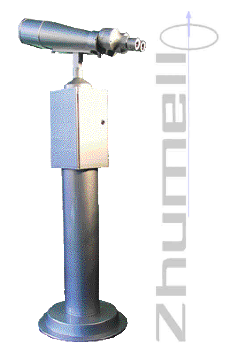
INOCULARS
INOCULARS
-O
-O

WARNINGS
•Bolt all pieces together to ensure stability.
•Do not attach power supply until assembly is completed.
Risk of electric shock.
•When disassembling, disconnect all cables to avoid
breakage or shock.
•Mount only on stable, level ground or platform.
•Secure base to Mounting platform to prevent
injury.
•Mount binoculars in dry area to increase
longevity.
•Maintain a clear pathway around binoculars to prevent user injury.
FEATURES
•Weather Resistant Coating
•AC or Battery Power Selection (12V Battery and 110V power
cord supplied)
•Adjustable Viewing Time Setting (0-50 mins./coin)
•External Interpupillary Distance Adjustment
•Coin-operated, Always Open, and service opera-
tion modes
•Rechargeable 12V Battery for Remote
Mounting Locations.
•Tamper-resistant Locking Coin Housing
•Multi-coated Optics

S
PECIFICATIONS
OPTICAL
25x100 40x100
POWER 25x 40x
EXIT PUPIL 4mm 2.5mm
EYE RELIEF 14mm 8.2mm
FIELD OF VIEW 43.6m@1000m 26.2m@1000m
RESOLUTION 2.4” 2.4”
FOCUS RANGE 30m ~ ∞ 60m ~ ∞
MECHANICAL
ORIENTAL RANGE: 0~315°
UP RANGE: 0~30°
DOWN RANGE: 0~45°
EYEPIECE DISTANCE RANGE: 58~72mm
SIZE OF BINOCULARS: 550x250x240mm
WHOLE HEIGHT: 1.5m (5ft.)
WHOLE WEIGHT: 84kg (185lbs.)
COIN DIAMETER RANGE: 18~31mm
COIN THICKNESS RANGE: 1.2mm~3.0mm
ELECTRICAL
POWER SUPPLY 85~265VAC (47~440HZ)
DC12V±1.5V
LOW DC POWER INDICATION: BELOW 10.5V
ENVIRONMENTAL
OPERATING ENVIRONMENT: 14°F~104°F (-10°C~40°C)

INSTALLATION
ASSEMBLY
Mount pier to base by inserting raised ring on pier into base open-
1
ing and securing with M10X20 mounting bolts (included) through
pre-drilled holes. Tighten bolts to ensure stability.
Secure base to mounting platform where unit will be used. (See
2
base installation below)
Attach mounting plate to top of control box with raised ring facing up. Secure mounting plate to control box using M2.5X5 hex
3
bolts (included). Tighten bolts to ensure stability.
Mount binoculars by setting them atop the mounting plate so
that mounting plate ring is centered in recess on the binocular
4
base and control cord enters the control box through the center hole
of the mounting plate. Attach binoculars to mounting plate using
M6X20 bolts (included). Tighten bolts to ensure stability.
Thread shutter control cable from binoculars onto shutter connec-
5
tion being careful not to bend connection prongs.
BASE INSTALLATION
Mount the pier base on stable, level ground using the included
mounting bolts. Anchor bolts into concrete or steel base which is
either anchored securely to the ground or a minimum of 10’ in diameter to ensure stability. If improperly mounted, the unit may tip.
 Loading...