

Zhone 6381-A4-200-1PR User Manual
6381-A4 Combination
Modem with in-line Filter
Users Guide
Document Part Number: 830-01935-01
November, 2008

Zhone Technologies, Inc.
@ Zhone Way
7001 Oakport Street
Oakland, CA 94621
USA
510.777.7000
www.zhone.com
info@zhone.com
COPYRIGHT ©2000-2008 Zhone Technologies, Inc. All rights reserved.
This publication is protected by copyright law. No part of this publication may be copied or
distributed, transmitted, transcribed, stored in a retrieval system, or translated into any human or
computer language in any form or by any means, electronic, mechanical, magnetic, manual or
otherwise, or disclosed to third parties without the express written permission from Zhone
Technologies, Inc.
Bitstorm, EtherXtend, IMACS, MALC, MXK, Raptor, SLMS, Z-Edge, Zhone, ZMS, zNID and the
Zhone logo are trademarks of Zhone Technologies, Inc.
Zhone Technologies makes no representation or warranties with respect to the contents hereof
and specifically disclaims any implied warranties of merchantability, non infringement, or fitness
for a particular purpose. Further, Zhone Technologies reserves the right to revise this publication
and to make changes from time to time in the contents hereof without obligation of Zhone
Technologies to notify any person of such revision or changes.
6381-A4 Router Users Guide 2

Important Safety Instructions
1. Read and follow all warning notices and instructions marked on the product or included in the
manual.
2. Slots and openings in the housing are provided for ventilation. To ensure reliable operation of
the product and to protect it from overheating, these slots and openings must not be blocked or
covered.
3. Do not allow anything to rest on the power cord and do not locate the product where persons
will walk on the power cord.
4. Do not attempt to service this product yourself, as opening or removing covers may expose you
to dangerous high voltage points or other risks. Refer all servicing to qualified service
personnel.
5. General purpose cables are used with this product for connection to the network. Special
cables, which may be required by the regulatory inspection authority for the installation site, are
the responsibility of the customer. Use a UL Listed, CSA certified, minimum No. 24 AWG line
cord for connection to the Digital Subscriber Line (DSL) network.
6. When installed in the final configuration, the product must comply with the applicable Safety
Standards and regulatory requirements of the country in which it is installed. If necessary,
consult with the appropriate regulatory agencies and inspection authorities to ensure
compliance.
7. A rare phenomenon can create a voltage potential between the earth grounds of two or more
buildings. If products installed in separate buildings are interconnected, the voltage potential
may cause a hazardous condition. Consult a qualified electrical consultant to determine
whether or not this phenomenon exists and, if necessary, implement corrective action prior to
interconnecting the products.
8. Input power to this product must be provided by one of the following: (1) a UL Listed/CSA
certified power source with a Class 2 or Limited Power Source (LPS) output for use in North
America, or (2) a certified transformer, with a Safety Extra Low Voltage (SELV) output having a
maximum of 240 VA available, for use in the country of installation.
9. In addition, since the equipment is to be used with telecommunications circuits, take the
following precautions:
— Never install telephone wiring during a lightning storm.
— Never install telephone jacks in wet locations unless the jack is specifically designed for wet
locations.
— Never touch uninsulated telephone wires or terminals unless the telephone line has been
disconnected at the network interface.
— Use caution when installing or modifying telephone lines.
— Avoid using a telephone (other than a cordless type) during an electrical storm. There may
be a remote risk of electric shock from lightning.
— Do not use the telephone to report a gas leak which is in the vicinity of the leak.
6381-A4 Router Users Guide 3

CE Marking
When the product is marked with the CE mark on the equipment label, a supporting Decla ratio n
of Conformity may be downloaded from the Zhone World Wide Web site at www.zhone.com.
FCC Part 15 Declaration
An FCC Declaration of Conformity may be downloaded from the Zhone World Wide Web site at
www.zhone.com.
This device complies with Part 15 of the FCC Rules. Operation is subject to the following two
conditions: (1) this device may not cause harmful interference, and (2) this device must accept
any interference received, including interference that may cause undesired operation.
The authority to operate this equipment is conditioned by the requirement that no modifications
will be made to the equipment unless the changes or modifications are expressly approve d by the
responsible party.
This equipment has been tested and found to comply with the limits for a Class B digital device,
pursuant to Part 15 of the FCC Rules. These limits are designed to provide reasonable protection
against harmful interference in a residential installation. This equipment generates, uses, and can
radiate radio frequency energy and, if not installed and used in accordance with the instructions,
may cause harmful interference to radio communications. However, there is no guarantee that
interference will not occur in a particular installation. If this equipment does cause harmful
interference to radio or television reception, which can be determined by turning the equipment
off and on, the user is encouraged to try to correct the interference by one or more of the
following measures:
— Reorient or relocate the receiving antenna.
— Increase the separation between the equipment and receiver.
— Connect the equipment into an outlet on a circuit different from that to which the receiver is
connected.
— Consult the dealer or an experienced radio/TV technician for help.
Notice to Users of the United States Telephone Network
The following notice applies to versions of the modem that have been FCC Part 68 approved.
This equipment complies with Part 68 of the FCC rules and the requirements adopted by the
Administrative Council for Terminal Attachment (ACTA). On the bottom side of this equipment is a
label that contains, among other information, a product identifier in the format
US:AAAEQ##TXXXX. If requested, this number must be provided to the Telephone Company.
This equipment is intended to connect to the Public Switched Telephone Network through a
Universal Service Order Code (USOC) type RJ11C jack. A plug and jack used to connect this
equipment to the premises wiring and telephone network must comply with the applicable FCC
Part 68 rules and requirements adopted by the ACTA. A compliant telephone cord and modular
plug is provided with this product. It has been designed to be connected to a compatible modular
jack that is also compliant.
The Ringer Equivalence Number (REN) is used to determine the number of devices that may be
connected to a telephone line. Excessive RENs on a telephone line may result in the devices not
ringing in response to an incoming call. In most but not all areas, the sum of RENs should not
6381-A4 Router Users Guide 4

exceed five (5.0). To be certain of the number of devices that may be connected to a line, as
determined by the total RENs, contact the local Telephone Company.
The REN for this product is part of the product identifier that has the format US:AAAEQ##TXXXX.
The digits represented by ## are the REN without a decimal point. For example, 03 represents a
REN of 0.3.
If the modem causes harm to the telephone network, the Telephone Company will notify you in
advance that temporary discontinuance of service may be required. But if advance notice is not
practical, the Telephone Company will notify the customer as soon as possible. Also, you will be
advised of your right to file a complaint with the FCC if you believe it is necessary.
The Telephone Company may make changes in its facilities, equipment, opera tions or
procedures that could affect the operation of the equipment. If this happens, the Telephone
Company will provide advance notice in order for you to make necessary modifications to
maintain uninterrupted service. If trouble is experienced with the modem, refer to the repair and
warranty information in this document.
If the equipment is causing harm to the telephone network, the Telephone Company may request
that you disconnect the equipment until the problem is resolved.
The user may make no repairs to the equipment.
Connection to party line service is subject to state tariffs. Contact the state public utility
commission, public service commission or corporatio n commission for information.
If the site has specially wired alarm equipment connected to the telephone line, ensure the
installation of the modem does not disable the alarm equipment. If you have questions about
what will disable alarm equipment, consult your Telephone Company or a qualified installer.
Notice to Users of the Canadian Telephone Network
NOTICE: This equipment meets the applicable Industry Canada Terminal Equipment Technical
Specifications. This is confirmed by the registration number. The abbreviation IC before the
registration number signifies that registration was performed based on a Declaration of
Conformity indicating that Industry Canada technical specifications were met. It does not imply
that Industry Canada approved the equipment.
NOTICE: The Ringer Equivalence Number (REN) for this terminal equipment is labelled on the
equipment. The REN assigned to each terminal piece of equipment provides an indication of the
maximum number of terminals allowed to be connected to a telephone interface. The termination
on an interface may consist of any combination of devices subject only to the requirement that the
sum of the Ringer Equivalence Numbers of all the devices does not exceed five.
If your equipment is in need of repair, contact your local sales representative, service
representative, or distributor directly.
6381-A4 Router Users Guide 5
!
CANADA - EMI NOTICE:
This Class B digital apparatus meets all requirements of the Canadian interference-causing
equipment regulations.
Cet appareil numérique de la classe B respecte toutes les exigences du règlement sur le matérial
brouilleur du Canada.
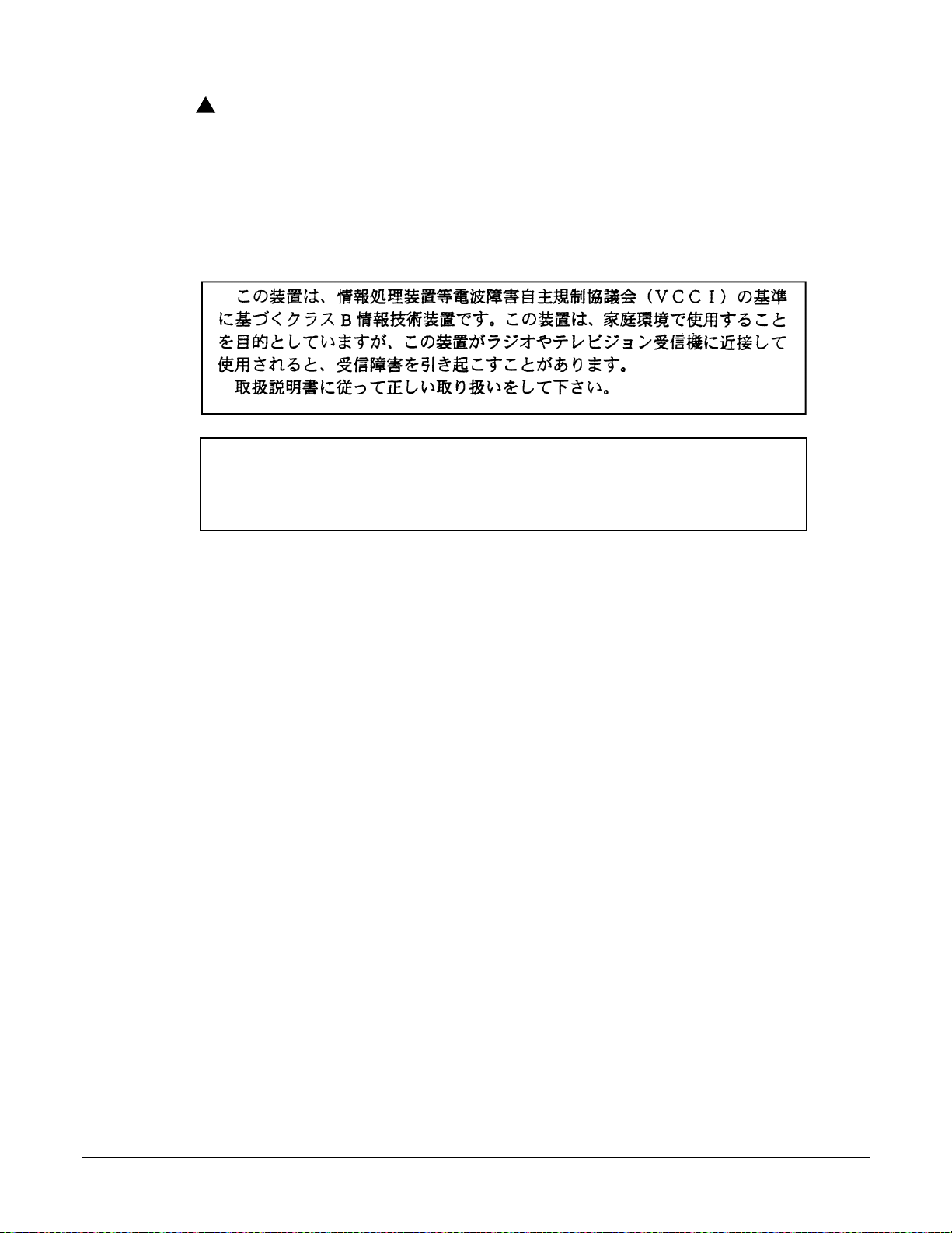
Japan Notices
This is a Class B product based on the standard of the Voluntary Control Council for
Interference from Information Technology Equipment (VCCI). If this is used near a
radio or television receiver in a domestic environment, it may cause radio
interference. Install and use the equipment according to the instruction manual.
6381-A4 Router Users Guide 6

Table of Contents
Important Safety Instructions................................................................................................................................3
CE Marking ......................................................................................................................................................4
FCC Part 15 Declaration..................................................................................................................................4
About This Guide................................................................................................................................................11
Style and notati on conventions......................................................................................................................11
Typographical conventions........................................................................................................................12
Acronyms.......................................................................................................................................................12
Contacting Global Service and Support.........................................................................................................14
Technical Support......................................................................................................................................14
Service Requirements ...............................................................................................................................14
Chapter 1 Introduction 15
System Requirements........................................................................................................................................15
Package Contents..............................................................................................................................................16
Safety Instructions..............................................................................................................................................16
Front Panel.........................................................................................................................................................17
Back Panel .........................................................................................................................................................18
Chapter 2 Hardware Installation and PC Setup 19
Overview ............................................................................................................................................................19
Connecting your hardware.................................................................................................................................19
Mounting the Modem..........................................................................................................................................20
Configuring Your Computer................................................................................................................................21
Windows 2000 ...............................................................................................................................................21
Windows XP...................................................................................................................................................22
Installing USB Drivers ........................................................................................................................................23
Windows 2000 ...............................................................................................................................................23
Chapter 3 The Web User Interface 29
Log in to the Modem...........................................................................................................................................29
Home..................................................................................................................................................................31
Quick Start......................................................................................................................................................32
WAN Setup.........................................................................................................................................................33
New Connection.............................................................................................................................................33
PPPoE Connection Setup .........................................................................................................................34
PPPoA Connection Setup..........................................................................................................................39
Static Connection Setup............................................................................................................................42
DHCP Connection Setup...........................................................................................................................44
Bridge Connection Setup...........................................................................................................................46
CLIP Connection........................................................................................................................................48
Modify a Connection..................................................................................................................................50
Delete a Connection..................................................................................................................................50
Modem...........................................................................................................................................................51
LAN Setup..........................................................................................................................................................52
LAN Configuration..........................................................................................................................................52
Firewall / NAT Services..................................................................................................................................55
Enable/Disable DHCP....................................................................................................................................55
Changing the Router's IP address.................................................................................................................57
Log Out...............................................................................................................................................................58
Advanced ...........................................................................................................................................................59
6381-A4 Router Users Guide 7

UPnP..............................................................................................................................................................59
SNTP..............................................................................................................................................................61
Port Forwarding .............................................................................................................................................63
DMZ Settings.............................................................................................................................................66
Custom Port Forwarding............................................................................................................................67
IP Filters.........................................................................................................................................................69
Custom IP Filters.......................................................................................................................................71
LAN Clients....................................................................................................................................................72
LAN Isolation..................................................................................................................................................75
TR–068 WAN Access.....................................................................................................................................76
Bridge Filters..................................................................................................................................................78
Dynamic DNS Client......................................................................................................................................80
IGMP Proxy....................................................................................................................................................82
Configure a WAN Interface as the Upstream IGMP Proxy........................................................................84
Configure a LAN interface as the Upstream Interface...............................................................................85
Static Routing.................................................................................................................................................87
Dynamic Routing............................................................................................................................................89
Quality of Service (QoS)................................................................................................................................92
Policy Database.............................................................................................................................................94
Ingress ...........................................................................................................................................................96
Ingress Untrusted Mode ............................................................................................................................96
Ingress Layer 2 Configuration ...................................................................................................................97
Ingress Layer 3 Configuration ...................................................................................................................98
Ingress Static Configuration.......................................................................................................................99
Ingress Payload Database Configuration................................................................................................100
Egress..........................................................................................................................................................103
No Egress Mode......................................................................................................................................103
Egress Layer 2 Configuration..................................................................................................................104
WLAN QoS Support ................................................................................................................................105
Shaper..........................................................................................................................................................105
Example 1: HTB Queue Discipline Enabled............................................................................................106
Example 2: Low Latency Queue Discipline Enabled...............................................................................107
Example 3: PRIOWRR Enabled..............................................................................................................107
Access Control.............................................................................................................................................108
Chapter 4 Tools 110
System Commands..........................................................................................................................................110
Remote Log - Router........................................................................................................................................111
User Management............................................................................................................................................112
Update Gateway...............................................................................................................................................113
Analyzer............................................................................................................................................................114
Ping Test...........................................................................................................................................................114
Modem Test......................................................................................................................................................115
Chapter 5 Status 116
Network Statistics.............................................................................................................................................116
Connection Status............................................................................................................................................117
DDNS Update St atus........................................................................................................................................117
DHCP Clients...................................................................................................................................................118
QOS-TCA NTCA Status....................................................................................................................................119
Modem Status..................................................................................................................................................120
Product Information..........................................................................................................................................120
System Log ......................................................................................................................................................121
6381-A4 Router Users Guide 8

Chapter 6 Troubleshooting 122
The Router Is Not Functional ...........................................................................................................................122
You Cannot Connect to the Router..................................................................................................................122
LEDs Blink in a Sequential Pattern..................................................................................................................122
The Status LED Continues to Blink..................................................................................................................122
The Status LED is Alway s Off...........................................................................................................................123
Diagnosing Problems using IP Utilities ............................................................................................................123
Ping..............................................................................................................................................................123
Nslookup......................................................................................................................................................124
Appendix A – Glossary 125
6381-A4 Router Users Guide 9

About This Guide
This guide is intended for use by installation technicians, system administrators, and network
administrators. It explains how to install the 1611-A3 router.
Style and notation conventions
The following conventions are used in this document to alert users to information that is
instructional, warns of potential damage to system equipment or data, and warns of potential
injury or death. Carefully read and follow the instructions included in this docum ent.
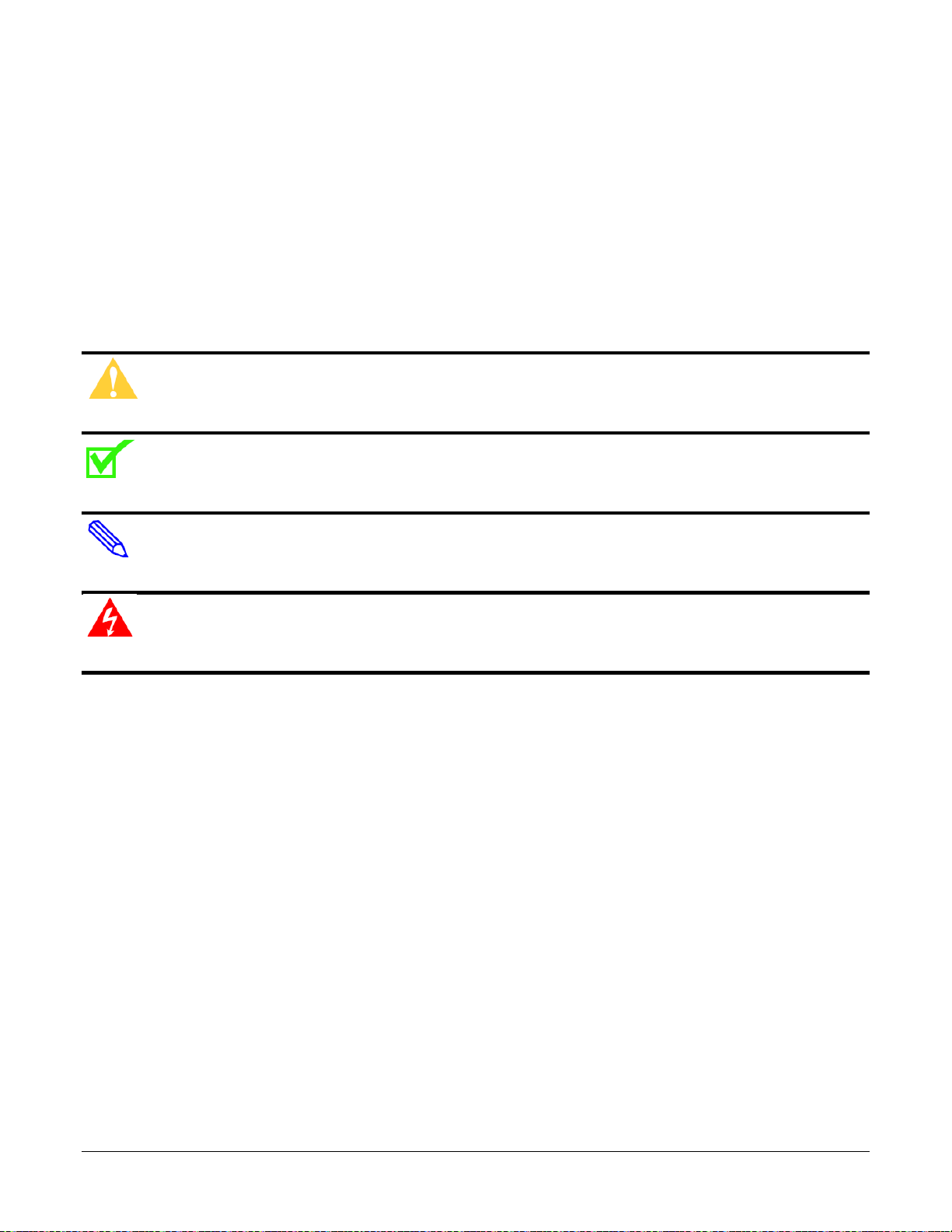
Caution: A caution alerts users to conditions or actions that could damage equipment or data.
Note: A note provides important supplemental or amplified information.
Tip: A tip provides additional information that enables users to more readily complete their tasks.
WARNING! A warning alerts users to conditions or actions that could lead to injury or death.
6381-A4 Router Users Guide 11

Typographical conventions
The following typographical styles are used in this guide to represent specific types of
information.
Bold
Fixed
Fixed Bold
Fixed Bold
Italic
Italic
PLAIN UPPER
CASE
Command Syntax
Used for names of buttons, dialog boxes, icons, menus,
profiles when placed in body text, and property pages (or
sheets). Also used for commands, options, parameters in
body text, and user input in body text.
Used in code examples for computer output, file names, path
names, and the contents of online files or directories.
Used in code examples for text typed by users.
Used in code examples for variable text typed by users.
Used for book titles, chapter titles, file path names, notes in
body text requiring special attention, section titles,
emphasized terms, and variables.
Used for environment variables.
Brackets [ ] indicate optional syntax.
Vertical bar | indicates the OR symbol.
Acronyms
The following acronyms are related to Zhone products and may appear throughout this manual:
Table 1: Acronyms and their descriptions
Acronym Description
ADSL Asymmetrical Digital Subscriber Line
AP Access Point
ACS Auto Configuration Server
DHCP Dynamic Host Configuration Protocol
DSL Digital Subscriber Line
EFM Ethernet in the First Mile
MALC Multi-Access Line Concentrator
MIB Management Information Bases
NAT Network Address Translation
NMS Network Management System
PVC Permanent Virtual Circuit
6381-A4 Router Users Guide 12

RADIUS Remote Authentication Dial In User Service
SHDSL Symmetric High-bit-rate Digital Subscriber Line
SLMS Single Line Multi-Service
SNMP Simple Network Management Protocol
TFTP Trivial File Transfer Protocol
VoIP Voice over IP
VoWi-Fi Voice-over-Wifi
VPN Virtual Private Network
WEP Wired Equivalent Privacy
Wi-Fi Wireless Fidelity (IEEE 802.11 wireless networking)
WMM Wi-Fi Multimedia
WPA Wi-Fi Protected Access
ZMS Zhone Management System
6381-A4 Router Users Guide 13

Contacting Global Service and Support
Contact Global Service and Support (GSS) if you have any questions about this or other Zhone
products. Before contacting GSS, make sure you have the following information:
• Zhone product you are using
• System configuration
• Software version running on the system
• Description of the issue
Technical Support
If you require assistance with the installation or operation of your product, or if you want to return
a product for repair under warranty, contact GSS. The contact information is as follows:
E-mail support@zhone.com
Telephone (North America) 877-ZHONE20 (877-946-6320)
Telephone (International) 510-777-7133
Internet www.zhone.com/support
If you purchased the product from an authorized dealer, distributor, Value Added Reseller (VA R),
or third party, contact that supplier for technical assistance and warranty support.
Service Requirements
If the product malfunctions, all repairs must be performed by the manufacturer or a Zhoneauthorized agent. It is the responsibility of users requiring service to report the need for service to
Zhone Global Services and Support (GSS).
6381-A4 Router Users Guide 14

Chapter 1 Introduction
The 6381-A4 Combo Router/Modem is a USB/Ethernet Modem that gives you the flexibility of
using either a USB or Ethernet connection.
The 6381-A4 provides the following features:
• Support for ADSL2+ and ReachDSL (ADSL/R)
• 10/100BaseT Ethernet port
• USB port
• The ability to connect multiple PCs to the Internet with just one WAN IP Address (when
configured in router mode with NAT enabled)
• A user-friendly web interface for configuration and monitoring
• Single-session IPSec and PPTP passthrough for Virtual Private Network (VPN)
• Preconfigured port settings for many popular games
• Ability to act as a DHCP Server on your network
• Compatibility with virtually all standard Internet applications
• Address filtering and DMZ hosting
• Downloadable flash software upgrades
• Support for up to eight Permanent Virtual Circuits (PVCs)
• Support for up to two PPPoE sessions
• TR-069 support
This User Guide will show you how to connect your 6381-A4 and how to customize its
configuration to get the most out of your new product.
System Requirements
In order to use your modem for Internet access, you must have the following:
• ADSL service subscription from your ISP.
• One computer with an Ethernet 10/100BaseT network interface card (NIC) or a free USB
port.
• (Optional) An Ethernet hub or switch, if you are connecting the device to several computers
on an Ethernet network.
• For system monitoring or configuration using the supplied web interface, a web browse r such
as Internet Explorer Version 5.5 or later.
6381-A4 Router Users Guide 15

Package Contents
In addition to this document, your package should arrive containing the following:
• 6381-A4 device
• USB Cable
• RJ–45 Cable
• RJ-11 Cable
• Power adapter
Safety Instructions
Place your modem on a flat surface close to the cables in a location with sufficient ventilation.
To prevent overheating, do not obstruct the ventilation openings of the device.
Plug the device into a surge protector to reduce the risk of damage from power surges and
lightning strikes.
Operate this equipment only from an electrical outlet with the correct power source as indicated
on the adapter.
Do not open the cover of the device. Opening the cover will void any warranties on the
equipment.
Unplug equipment first before cleaning. A damp cloth can be used to clean the equipment. Do not
use liquid / aerosol cleaners or magnetic / static cleaning devices.
6381-A4 Router Users Guide 16
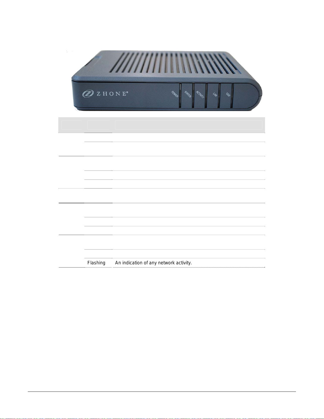
Front Panel
LED Mode INDICATION
Power
Status
Activity
LAN
USB
Solid Power is supplied to the modem.
No light
Solid
No Light No carrier signal.
Flashing Carrier has been detected and modem is trying to train.
Flashing
Solid
No Light Connection not established or cable is not connected
Flashing An indication of any network activity.
Solid
No Light Connection not established or cable is not connected
Flashing An indication of any network activity.
The modem may not be turned on. Check if the power adapter is
connected to the modem and plugged in.
The DSL interface is successfully connected to a device through the
LINE port.
Flickers according to the amount of transmitted or received DSL
traffic present.
Ethernet interface is successfully connected to a device through the
LAN port.
USB interface is successfully connected to a device through the LAN
port.
6381-A4 Router Users Guide 17
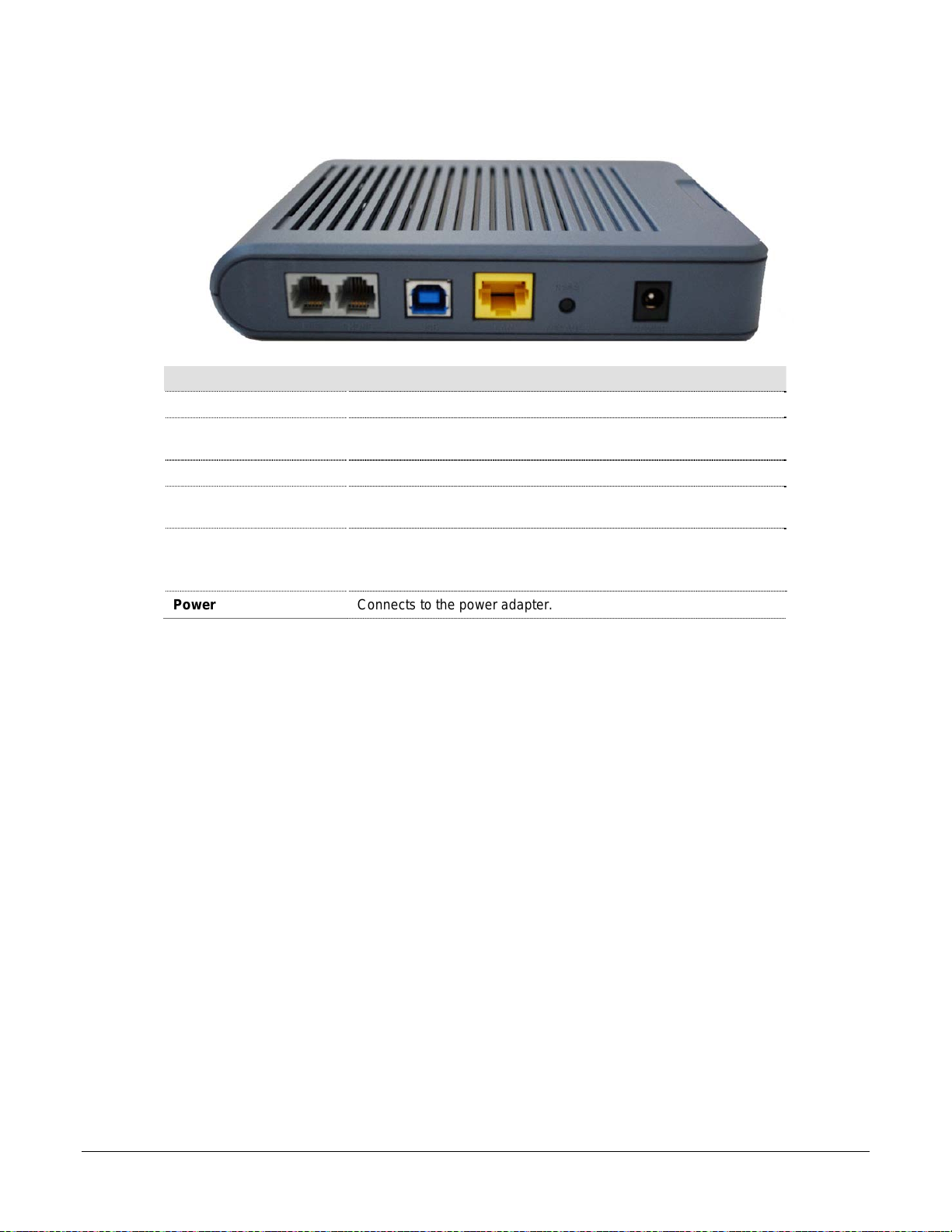
Back Panel
Port Description
Line
Phone
USB
LAN
Reset / Default
Power
RJ-11 cable connects to the phone jack in the wall.
RJ-11 cable connects to telephone (no external splitter necessary;
unit has internal splitter).
USB cable connects to the PC.
RJ-45 connects the unit to an Ethernet device such as a PC or a
switch.
No reset function on this model.
Default settings—press the button for 7 seconds or longer to
revert to factory default settings.
Connects to the power adapter.
6381-A4 Router Users Guide 18
Chapter 2 Hardware Installation and PC Setup
Overview
This chapter provides basic instructions for connecting the router to a computer or a LAN and to
the Internet using DSL. The first part provides instructions to set up the hardware, and the second
part describes how to prepare your PC for use with the router. Refer to Chapter 3, Using the Web
Interface for configuration instructions.
It is assumed that you have already subscribed to DSL service with your telephone company or
other Internet service provider (ISP).
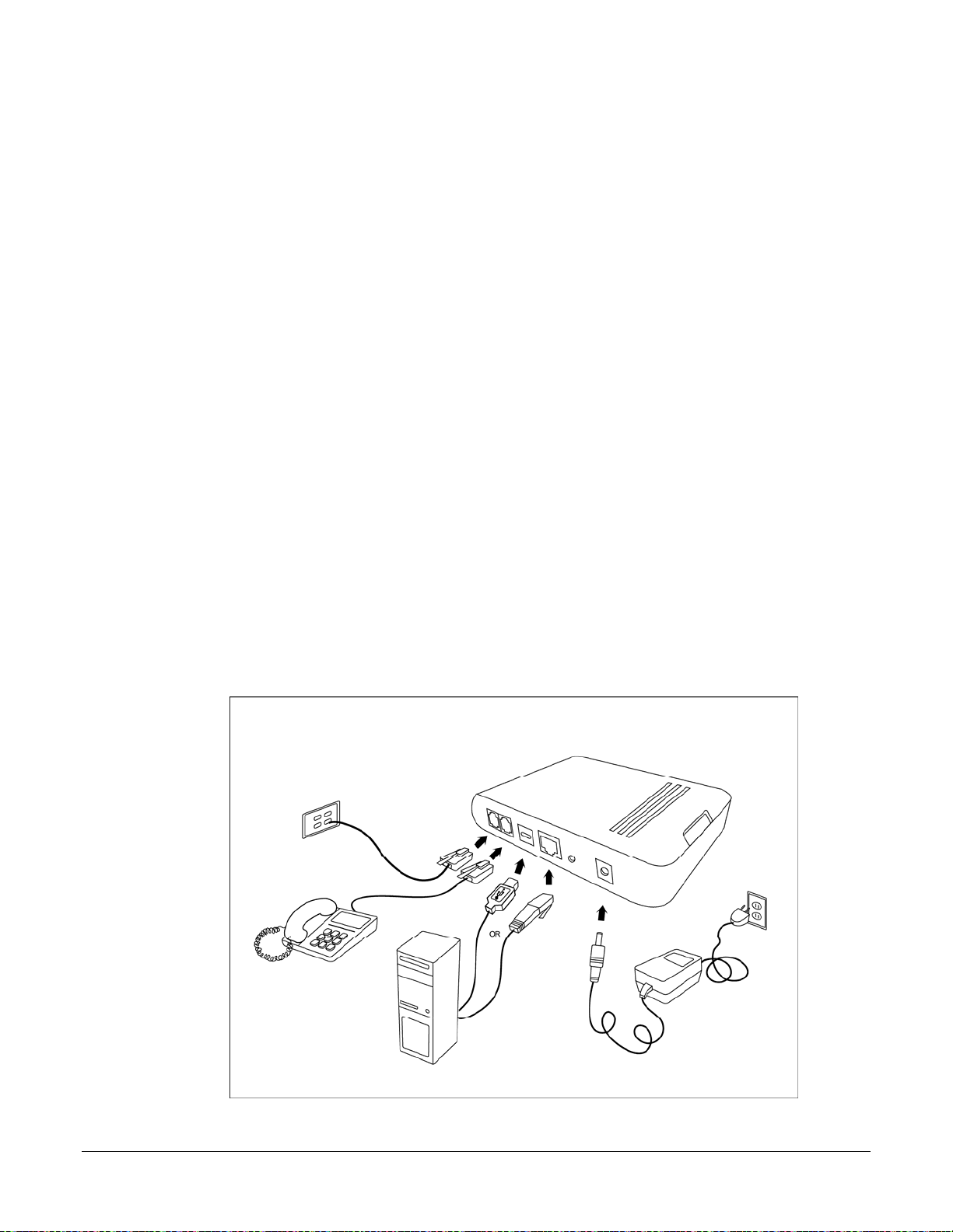
Connecting your hardware
Shut down your PC before connecting the router. To connect your modem:
1. Connect the ADSL Line and Telephone
Connect one end of an RJ-11 cable from your ADSL connection and the other end to the
LINE port of the modem.
Use a second RJ-11 cable to connect between a telephone and the PHONE port of the
modem.
2. Connect the PC to the Modem
To use the Ethernet connection, connect the Ethernet cable from the computer directly to the
modem. Connect one end of the Ethernet cable to the port labelled LAN on the back of the
modem and attach the other end to the Ethernet port of your computer.
6381-A4 Router Users Guide 19
You can also use the supplied USB cable to connect your computer directly to the modem.
Connect one end of the USB cable to the USB port on the back of the modem and connect
the other end to a free USB port on your PC. The Found New Hardware Wizard will open on
your PC. See USB Driver Installation instructions below.
If your LAN has more than one computer, you can attach one end of an Ethernet cable to a
hub or a switch and the other to the Ethernet port (labelled LAN) on the modem. Note that
either a crossover or straight-through Ethernet cable can be used. The modem automatically
recognizes the type of connection that is required.
3. Connect the Power Adapter
Complete the process by connecting the AC power adapter to the POWER connector on the
back of the device and plug the adapter into a wall outlet or power strip. Then turn on and
boot up your PC and any LAN devices, such as hubs or switches, and any computers
connected to them.
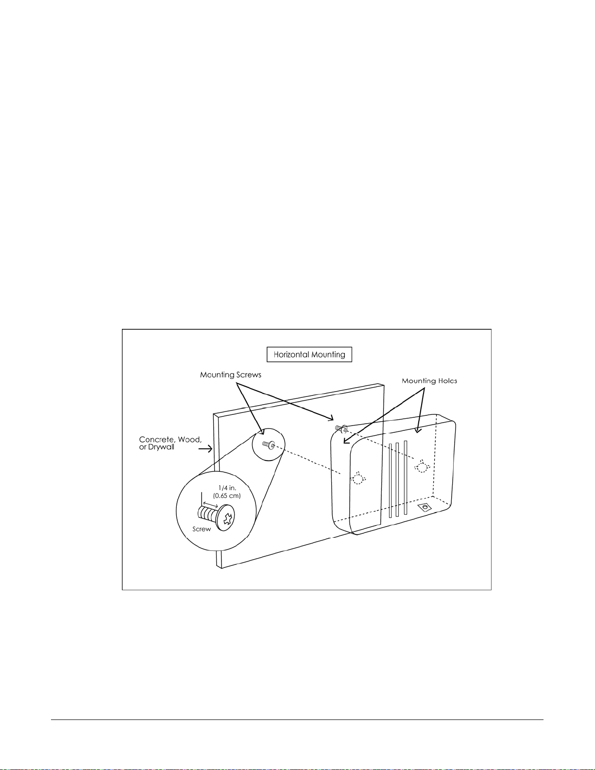
Mounting the Modem
The modem can be mounted on the wall with two screws. Mounting can be done on wall material
including concrete, wood, or drywall. Select an appropriate location free from obstructions or any
possible interference. Make sure the cables can be easily attached to the modem without strain.
The illustration below shows how to mount the modem horizontally on a wall.
6381-A4 Router Users Guide 20

Configuring Your Computer
Prior to accessing the modem through the LAN or the USB port, note the following necessary
configurations—
• Your PC’s TCP/IP address: 192.168.1.__( the last number is any number between 2 and
254)
• The modem’s default IP address: 192.168.1.1
• Subnet mask: 255.255.255.0
Below are the procedures for configuring your computer. Follow the instructions for the operating
system that you are using.
If you used the Ethernet cable to connect your router and PC, you do not need any specific driver
installation and you can skip Windows USB Driver Installation, below. If you used the USB cable
on a PC running a Windows operation system, install the provided USB driver. Windows 95 and
Windows NT 4.0 do not support USB without additional software (not included with your router). If
USB driver installation fails under those operating systems, contact your service provider.
Windows 2000
1. In the Windows taskbar, click the Start button and point to Settings, Control Panel, and
Network and Dial-up Connections (in that order).
2. Click Local Area Connection. When you have the Local Area Connection Status window
open, click Properties.
3. Listed in the window are the installed network components. If the list includes Internet
Protocol (TCP/IP), then the protocol has already been enabled, and you can skip to Step
10.
4. If Internet Protocol (TCP/IP) does not appear as an installed component, then click Install.
5. In the Select Network Component Type window, click on protocol and then the Add
button.
6. Select Internet Protocol (TCP/IP) from the list and then click on OK.
7. If prompted to restart your computer with the new settings, click OK.
8. After your computer restarts, click the Network and Dial-up Connections icon again, and
right click on the Local Area Connection icon and then select Properties.
9. In the Local Area Connection Properties dialog box, select Internet Protocol (TCP/IP)
and then click Properties.
10. In the Internet Protocol (TCP/IP) Properties dialog box, click the radio button labelled Use
the following IP address and type 192.168.1.x (where x is any number between 2 and 25 4)
and 255.255.255.0 in the IP address field and Subnet Mask field.
11. Click OK twice to save your changes and then close the Control Panel.
6381-A4 Router Users Guide 21

Windows XP
1. In the Windows taskbar, click the Start button and point to Settings and then click Network
Connections.
2. In the Network Connections window, right click on the Local Area Connection icon and
click on Properties.
3. Listed in the Local Area Connection window are the installed network components. Make
sure the box for Internet Protocol (TCP/IP) is checked and then click Properties.
4. In the Internet Protocol (TCP/IP) Properties dialog box, click the radio button labelled Use
the following IP address and type 192.168.1.x (where x is any number between 2 and 25 4)
and 255.255.255.0 in the IP address field and Subnet Mask field.
5. Click OK twice to save your changes and then close the Control Panel.
6381-A4 Router Users Guide 22
Installing USB Drivers
The following instructions will guide you through the installation of the USB driver.
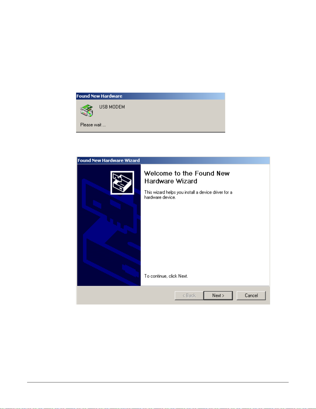
Windows 2000
1. When you attach the USB cable into the modem for the first time and turn on the device, the
Found New Hardware window will pop up.
2. The Found New Hardware Wizard will appear shortly after informing you that a USB driver
is needed. Click Next to continue with the installation.
6381-A4 Router Users Guide 23
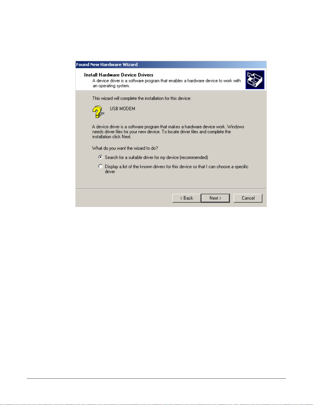
3. The Install Hardware Device Drivers screen explains what a driver is and why you need it
in order to run your modem using the USB plug. Typically, you will need to select the first
option, the recommended option of searching for a suitable driver for your device. Click
Next.
6381-A4 Router Users Guide 24
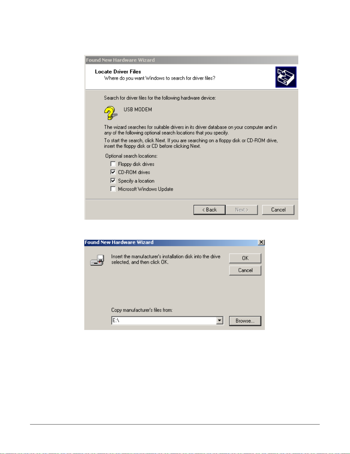
4. Insert the USB driver installation CD if you have not already done so. Click CD-ROM drives
and Specify a location and click Next.
5. Click Browse and select the E: drive where the CD-ROM is located. Then click OK.
6381-A4 Router Users Guide 25
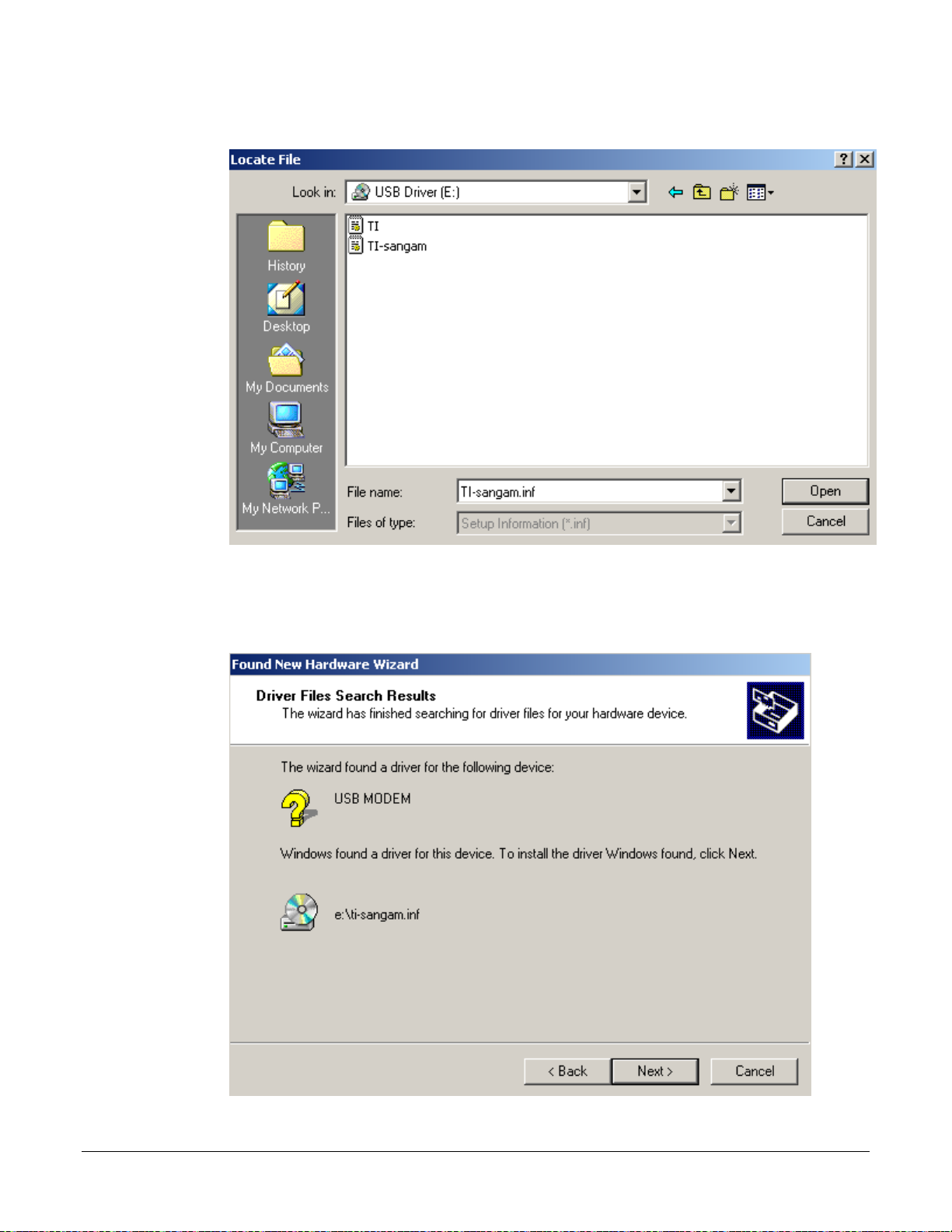
6. Select the drive and the .inf files on the installation CD will appear, with the TI-sangam.inf
file automatically appearing in the File name: drop-down window. Click Open to continue.
7. The Driver Files Search Results step allows you to confirm the .inf file that will be installed,
thus allowing you to confirm that ti-sangam.inf is the USB driver that will be installed. Click
Next.
6381-A4 Router Users Guide 26
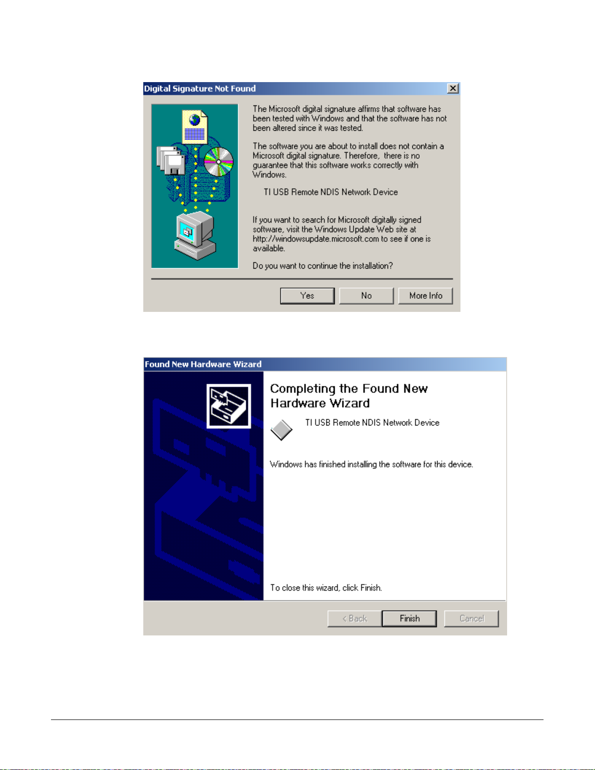
8. Click Yes to continue the installation.
9. Once the driver has been installed, the Found New Hardware Wizard confirms installation.
Click Finish.
6381-A4 Router Users Guide 27

Chapter 3 The Web User Interface
The 6381 A4 combination modem/router has a Wide Area Network (WAN) connection which
connects to your phone line. This connects to your Internet Service Provider (ISP) via the phone
line. The Local Area Network (LAN) connection is where you plug in your local computers to the
router. The router is normally configured to automatically provide all the PCs on your network with
Internet addresses.
To set up your modem with a basic configuration, from the top navigation bar, select Setup.
Setup is divided into two subsections—LAN Setup and WAN Setup.
If you connected a PC (rather than a h ub or a switch) direct ly to the router, your LA N consists of that PC.
You may also create connections for various protocol options by creating new connections.
To configure your modem you will first need to log in to the modem.
Notes:
• Before configuring your router, make sure you have followed the instructions in Chapter 2
Hardware Installation and PC Setup.
• If you see a login redirection screen when you access the web interface, verify that
JavaScript support is enabled in your browser. Also, if you do not get the screen shown
below, you may need to delete your temporary Internet files.
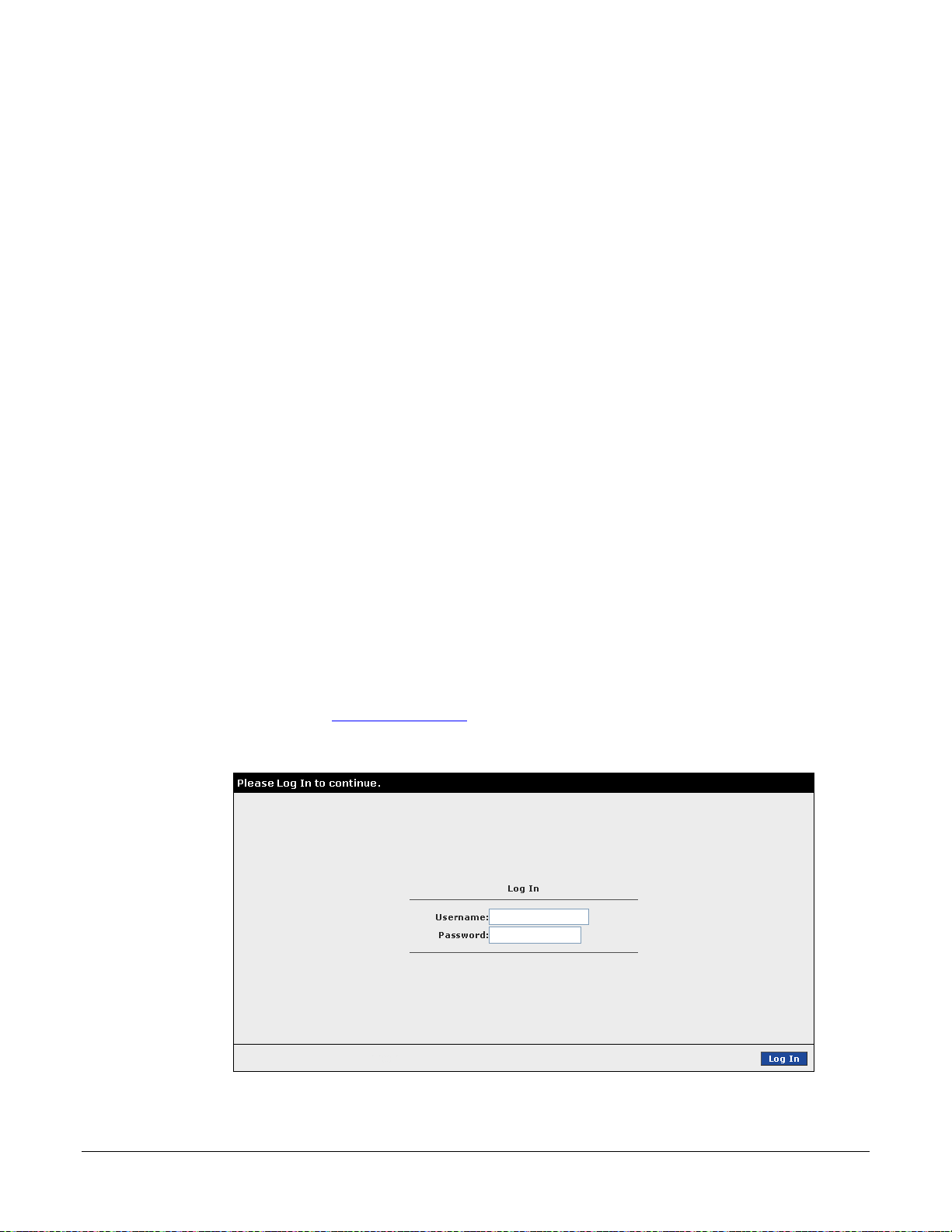
Log in to the Modem
This section will explain how to log in to your modem.
1. Launch your web browser.
2. Enter the URL
A login screen like the one below will be displayed after you connect to the user interface.
http://192.168.1.1 in the address bar and press Enter.
3. Enter the default user name and password, and then click on OK to display the user
interface.
6381-A4 Router Users Guide 29

The user name / password are Admin / Admin and both are case sensitive.
6381-A4 Router Users Guide 30
 Loading...