

Page 1

SlfiNIN~~IJ(_
User
Manual
~~-r~
~
Zhiyun
Page 2
Disclaimers and warnings
Shining User Manual
Disclaimers
Congratulations
disclaimer
By
using
fully.
using
purposes
policies
Do
modification
injury.
liability.
from
You shall
Shining
number.
upgrade.
If
or
Zhiyun.
registered
copyrighted
copied
this
You
this
and
not
modify
By
Zhiyun
the
use
in www.zhiyun-tech.com . Please
If
you
meet
Zhiyun
All
or
Using
on
carefully
product,
agree
that
product,
that
are
guidelines.
or
adjust
or
misuse,
the
using,
assumes
of
this
get
product
not,
please
some
problems
client
service
names
trademarks
by
Zhiyun,
translated
the
before
you
and
proper
setting
product.
of
in
manual
and
purchasing
using
you
hereby
are
responsible
for
any
and
the
Shining.
no
liability
up,
no
liability
information
download
while
center
products,
of
their
with
all
any
form
warnings
your
new
product.
to
for
Zhiyun
assumed
for
damages
and
user
check
the
up
Zhiyun
etc.,
reserved.
permission.
Zhiyun
this
your
with
latest
the
owner
this
agree
consequences
in
accordance
As
shall be
or
assembling
and
use
setting
for
help.
brands,
respective
rights
without
product.
disclaimer
own
thereof.
local
has
no
or
of
the
or
manual
the
one.
product,
and
appearing
companies.
No
part
Please
and
conduct
You
agree
regulations,
control
product,
latest
accepted
injuries
through
manual
Zhiyun
please
Shining
in
of
over
this
this
signify
and
any
to
use
terms
use,
for
any
the
user
incurred
visiting
according
shall
not
turn
are
registered
manual
This
product
product
read
that
content
this
setup,
resulting
accepts
directly
the
inform
to
the
this
manual
you
have
created
product
and
any
final
or
theme
to
of
authorized
trademarks
are
trademarks
and
or
manual
read
while
only
applicable
assembly,
damage
all
resulting
indirectly
page
the
version
the
manual
agent
manual
shall be
and
it
for
or
of
of
or
are
Legend
CD
Important
Summary
Developed
forward
The
sizes
A
brushless
axes.
vibration
perfectly
Tilt
Following
for
in
camera
technology
and
weights,
gimbal
Shining
to
less
steady.
filmmaking
built
can
Mode.
stabilization
into
to
be
stabilized
stabilization
processes
than
±0.05"
The
Shining
~
References
professionals,
technology.
the
Zhiyun
during
system
movement
of
translated
can
be
Shining
filming.
is
not
calculation
used
in
or
Definitions
the
Zhiyun
The
Shining
allows a broad
simply
three
movement,
two
operation
Shining
is
light,
spectrum
brush
in
milliseconds,
meaning
modes:
marks a generational
small
and
convenient
of
less
that
Locking
cameras,
motors
which
the
camera
Mode
of
moving
reduces
will
and
leap
to
use.
varying
on
three
angular
remain
Pan
and
Page 3
Shining User Manual
Shining
I, Disclaimers and
II, Using
Ill,
Summary
IV,
Shining
1
.Shinning
2.Packing
3.Shining
V,
Getting
1 . 1
8650
2.Turning
3.Assembling
4.1nstalling
5.Mounting
6.Configuring
VI,
Balancing
1 .Balancing
2.Balancing
3.Balancing
4.Balancing
5.Advanced Roll
the
Manual
Introduction
Features
List
Diagram
Started
Li-ion
Battery
on
the
Shining
the
Handle
Handle
the
Camera
the
Handle
the
Vertical
the
Roll Axis
the
Tilt
the
Pan Axis
Adjustment
Bar
Axis
Contents
Warnings
Bar
onto
the
Gimbal
Bar
Tilt
3
4
6
7
7
8
9
9
10
12
12
13
13
13
VII,
Operation
1
.Underslung
2.Upright
3.Briefcase
VIII,
IX,
X,
Technical
Status
Maintenance
Specifications
Modes
Status
Status
Parameters
of
Gimbal
14
14
15
15
16
16
Page 4
Features Shining User Manual
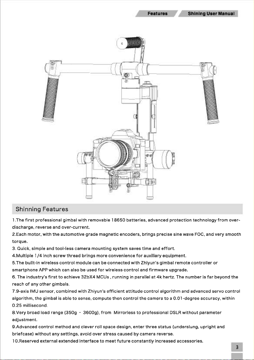
Shinning Features
1 .The
first
professional
discharge,
2.Each
torque.
3. Quick,
4.Multiple
5.The
smartphone
6. The
reach
7.9-axis
algorithm,
0.25
8.Very
adjustment.
9.Advanced
briefcase)
1 O.Reserved
reverse
motor,
with
simple
1/4
inch
built-in
wireless
APP
industry's
of
any
other
IMU
sensor,
the
gimbal
millisecond.
broad
load
control
without
external
and
the
and
screw
which
first
gimbals.
range
any
tool-less
combined
method
gimbal
with
over-current.
automotive
camera
thread
brings
control
module
can
also
be
to
achieve
32bX4
with
is
able
to
sense,
(350g -3600g),
and
clever
settings,
extended
avoid
interface
removable
grade
magnetic
mounting
more
can
be
used
for
MCUs,
Zhiyun's
compute
from
roll
over
to
18650
encoders,
system
convenience
connected
wireless
running
efficient
then
Mirrorless
space
design,
stress
caused
meet
future
batteries,
saves
with
control
in
parallel
attitude
control
enter
by
constantly
advanced
brings
time
for
auxiliary
Zhiyun's
and
firmware
at
control
the
camera
to
professional
three
camera
protection
precise
and
effort.
equipment.
gimbal
upgrade.
4k
hertz.
algorithm
to a 0.01-degree
DSLR
status
reverse.
increased
technology
sine
wave FOG,
remote
controller
The
number
and
advanced
without
(underslung,
accessories.
and
very
or
is
far
beyond
servo
accuracy,
parameter
upright
and
from
within
over-
smooth
the
control
Page 5
Shining User Manual
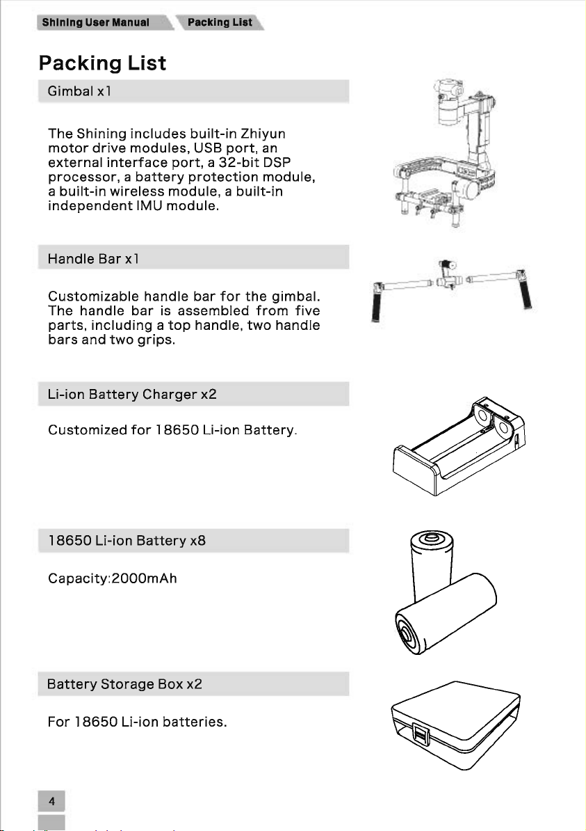
Packing List
Gimbal
The
motor
external
processor, a battery
a
independent
Handle
Customizable
The
parts,
bars
Li-ion
Customized
x1
Shining
drive
interface
built-in
wireless
Bar
handle
including a top
and
two
Battery
includes
modules,
module, a built-in
IMU
module.
x1
handle
bar
is
grips.
Charger
for
18650
port, a 32-bit
built-in
USB
port,
protection
bar
for
assembled
handle,
x2
Li-ion
Zhiyun
an
DSP
module,
the
gimbal.
from
two
handle
Battery.
five
,
.. ·.
,,~oc·.·.
\
1
8650
Li-ion
Battery
Capacity:2000mAh
Battery
For 1 8650
Storage
Li-ion
Box
batteries.
x8
x2
Page 6
Shining User Manual
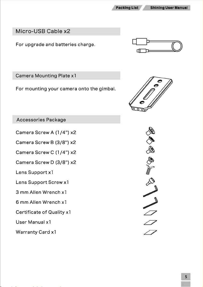
Micro-USB
For
upgrade
Camera
For
Accessories
Camera
Camera
Camera
Camera
Mounting
mounting
Screw A (1
Screw B (3/8")
Screw C (1
Screw D (3/8")
Cable
and
batteries
Plate
your
camera
Package
/4")
/4")
x2
x1
x2
x2
x2
x2
charge.
onto
the
gimbal.
~
~
~
~
Lens
Support
Lens
Support
3
mm
Allen
6
mm
Allen
Certificate
User
Manual
Warranty
x1
Screw
Wrench
Wrench
of
Quality
x1
Card
x1
x1
x1
x1
x1
IT
;)
/
~
~
~
Page 7

Shining
UMr
llenuel
Dlegrem
Shining
Diagram
[16]
[15)
1.1/4
Screw
thread
2.3/8
Screw
thread
3.
Top
Handle
4.Side
Handle
5.Quick Release
6.Pan
Motor
7.Pan
Aqjustment
8.USB
Port
9.Power
1
11.Roll
12.TIIt
13.Fore
14.Tilt
15.Roll
16.Extended
Button
O.Batteries
Motor
Motor
and
Vertical
Adjustment
compartment
Aft
Function
Bar
Mount
Slider
Adjustment
Adjustment
Interface
Page 8

Shining Uaer
llanual
Getting
1
8650
Li-ion
Zhiyun
battery
the
the
Protection
Protection
18650
designed
using
hours.
note
Power
Over-Discharge
Short-Circuit
Zhiyun
Type
Capacity
Charging
for
your
with
18650
Shining
(When
the
cathode
Protection
18650
Environment
Shinning,
Li-ion
Started
Battery
Li-ion
battery
the
Shining.
be
sure
Zhiyun
approved
batteries
has a maximum
installing
and
anode.)
Li-ion
Temperature
the
Battery
was
specially
Before
you
to
charge
charger.
are
fully
run-time
batteries,
Discharging
reaches
Automatically
detected
start
the
When
charged,
of
six
please
stops
3.0V,
Speci
automatically
preventing
cuts
power
fications
when
over-discharge
supply
the
when a short
Li-ion
2000mAh
o·
c-40'
battery
damage
circuit
c
voltage
is
Operating
Charging/Discharging
Humidity
o
Note:
than
o
Always
resulting
Turning
Press
standby
Shining
Following
be
3.0V
use
the
Environment
sure
that
cannot
Zhiyun
from
the
on
the
Power
mode.
After
starts
to
Mode.
Environment
every
run
the
approved
use
of
Shinning
button,
about
work.
The
Temperature
battery
gimbal.
non-Zhiyun
Shining
is
chargers.
enters
seven
seconds,
default
fully
Relative
charged
Zhiyun
approved
mode
is
in
the
takes
no
chargers.
-10-40'
<8096
right
way,
any
responsibility
c
battery
for
voltage
any
consequences
lower
Page 9

Shining User Manual Getting Started
Assembling
l.Adjust
the
proper,
angle
the
is
tighten
the
handle
needed,
the
Handle
bar
to
loosen
screw
Bar
the
angle
the
again.
screw
you
and
need,
pull
then
the
tighten
handle
in
the
screw.
radial
If a re-adjustment
direction,
when
the
of
angle
is
2.Attach
3.Attach
the
the
-
handle
grips
to
bars
the
to
both
handle
sides
bar
and
--
of
the
lock
top
them
handle
in
the
and
tighten
preferred
the
grip
position.
screws.
Page 10

Getting Started
Shining
User
Manual
Installing
1.Piace
and
2.Hold
degrees
the
tighten
the
pan.
handle
gimbal
Mounting
The
Shining
install
and
cameras.
Black
Black Magic Pocket
Canon
Canon
CD
Other
Magic
1 De
50
MK
1.
Make
camera.
2.
Camera
center
maximum
The
maximum
base
plate,
3.
To
avoid
connection
Handle
bar
the
lock-knob.
by
The
installation
the
Camera
uses
an
remove
cameras
Cinema
Cinema
II
sure
the
Size
of
gravity
width
is
187
obstructing
cable
Bar
onto
in
position
the
grips,
make
is
adjustable
the
camera.The
similar
Camera
Camera
g1mbal
IS
Requirements:
on
the
is
height,
mmas
is
camera
169
mm
measured
shown
camera
recommended.
the
Gimbal
as
shown
sure
complete.
camera
Shining
in size
and
Canon
Canon
Canon
Canon
not
turned
The
base
as
shown
from
in
the
movement,
below,
that
the
mounting
has
weight
50
60
70
C100
on
when
maximum
plate
in
the
image
the
top
image
then
gimbal
plate
been
may
MK
depth
is 1
of
to
the
the
slide
is
not
that
tested
also
be
Ill
mountmg
from
20
mm.
to
the
the
camera
right.
use
of
it
horizontally
obstructed
allows
with
compatible.
the
the
The
right.
soft
into
during a 360
you
to
the
Nikon
Panasonic
Panasonic
Sony
easily
following
0800
a 7
the
gimbal
GH3
GH4
series
balance,
types
of
1.Attach
or
D.
Camera
C
and D only
Secure
two
mounting
holes,
according
2.1nstall
lens.
Then
the
camera
screws A and B only
fit
the
holes
lens
slot
to
your
support
the
the
the
camera
tighten
mounting
of
the
as
firmly
are
available
camera's
by
thumbscrew.
plate
fit
mounting
as
possible.
on
configuration.
gently
to
your
the
holes
plate.
your
pushing
camera
of
Be
Some
cameras
camera,
it
up,
the
sure
use
so
using
the
mounting
to
use
have
them
that
it
provided
plate,
the
correct 1 /4"
two
both.
is
applying
camera
while
tripod
Choose
light
screws
the
camera
or
3/8"
mounting
the
correct
pressure
-
A,B,C
screws
screws.
holes.
screw
to
the
If
Page 11

Shining User Manual Getting Started
Why
do
you
Certain
Canon
the
the
and
directly
resulting
If
the
·
The
lens
CD
·
Ensure
tightening
3.With
the
receiver
the
until
camera.
need a lens
cameras
50
camera
lens
support
the
camera
to
oscillations
lens
lens
types.
alignment
gimbal
the
MK
II
as
one
the
lens,
support
support
the
lens
facing
safety
support?
have a
and
MK
solid
must
body
resulting
fits,
can be
of
support.
outward
lock
very
Ill
unit.
be
used.
may
allow
will be
it's
best
installed
the
engages.
tight
have
very
If
the
This
vibrations
in
the
transmitted
to
camera
on
lens
securing
loose
mounted
is
because a loose
that
two
masses
to
use
it
at
facing
outward
plate
and
the
tuning
Make
sure
lens
camera
travel
the
IMU,
all
times.
then
stand,
the
system,
securing
has a
through
shaking
causing
or
inward
tighten
slide
gimbal
and
some
systems.
loose
connection
to
at
different
the
to
the
mounting
the
mounting
is
not
turned
cameras
The
lens
between
the
frequencies.
whole
accommodate
Shining
securing
camera
gimbal
screw,
plate
on
when
such
the
as
balances
system,
lens
but
not
The
to
shake.
different
before
into
balancing
the
the
4.When
adjust
the
the
tightness
Configuring
The
customized
steps
below.
l.Loosen
the
camera
the
handle
two
grip
achieves a rough
of
the
clamp
with
Handle
screws
bar
of
Bar
the
Shining
where
balance,
an
the
handle
Zhiyun
can
be
tighten
Allen
removed.
bar
meets
the
camera
Wrench.
If
necessary,
the
gimbal,
base
as
side
by
following
shown.
clamp.
You
the
can
Page 12

GeHing Started Shining User Manual
2.Remove
3.You
4.The
the
can
remove
resulting
grips
configuration
Balancing
To
obtain
the
balance
acceleration
will
also
balanced
best
is
critical
(running,
offer a longer
prior
to
from
one
or
performance
for
shots
horseback
battery
turning
the
both
on
handle
sides
is
shown
where
the
Shining
bar.
of
the
below.
from
the
riding,
runtime.
handle
the
Shining,
Shining
biking,
There
and
setting
bar.
will be
car
mounts,
are
up
proper
subjected
three
the
software.
balancing
to
helicopters,
axes
that
is a
extreme
etc.).
need
must.
movements
proper
to
be
accurately
Accurate
or
balance
•
CD
• Be
The
camera
and
balancing
remove
sure
it
prior
that
needs
the
to
the
Shining's
to
be
fully
camera
balancing.
power
configured,
on
the
gimbal.
is
turned
If
off
with
the
while
all
accessories,
camera
balancing
the
prior
camera.
has a lens
cap,
to
installing
be
sure
to
Page 13

Shining User Manual
Step
1:
Balancing
1
.Rotate
adjustment
2.Gently
upwards
3.Tighten
binding
tilt
CD
Step
angle,
which
2:
the
Tilt
tabs.
slide
the
when
released.
the
tabs
in
the
tilt
and
it
Ensure
the
not
match
would
Balancing
will
the
Axis
so
that
camera
and
manually
motor.
When
stay
in
that
measurement
up,
the
assembly
cause
the
the
Vertical
the
camera
mount
crossbar
rotate
proper
position.
marks
tilt
motor
Roll
Axis
Tilt
the
balance
match
could
to
lens
is
forwards
assembly,
up
possibly
bind.
pointing
is
achieved,
on
either
be
upward
or
backwards
simulating
you
side
skewed
and
tilt,
can
of
the
higher
loosen
until
to
rotate
vertical
or
the
the
camera
ensure
the
camera
bars.
lower
two
there
on
vertical
points
to
If
they
one
is
no
any
do
side,
1
.Loosen
2.Siide
the
3.Tighten
When
CD
knobs a few
excessively.
the
two
camera
the
lock-knobs
left
two
lock-knobs
adjusting
turns
or
right
the
to
to
roll
to
allow
until
the
lock
balancing
allow
the
the
the
camera
Roll
Axis
camera
position
camera
and
mounting
remains
mounting
of
the
base
to
plate
level.
plate
in
camera,
slide. Do
to
slide
position.
only
loosen
not
loosen
left
the
the
and
right.
two
lock-knobs
lock-
Page 14

Step
3:
1
.Loosen
forwards
2.Siide
the
adjustments
3.Tighten
balanced,
Step
4:
1
.Loosen
assembly.
2.While
by
balanced.
Note:
lifting
it
the
is
Balancing
the
camera
and
backwards.
camera
are
required
the
side
the
camera
Balancing
the
clamp
Identify
one
Tighten
normal
Shining
side
if
of
the
that
the
base's
forwards
to
clamp
should
the
on
the
the
Shining
is
resting
the
handle
clamp
the
rotary
Tilt
side
or
achieve
to
lock
be
Pan
pan
on
after
Axis
clamp
backwards
the
the
able
to
remain
Axis
axis
via
is
front
the
tuning
bar.
If
balancing
knob
still
to
allow
until
proper
camera
3mm
heavy
stand,
the
camera
is
can
the
the
balance.
and
mounting
steady
at
allen
wrench
or
rear
heavy.
try
does
complete.
rotate
after
camera
tilt
axis
any
rotating
not
tightening
and
remains
plate
given
and
the
swing,
Shining User Manual
mounting
level.
Only
in
position.
tilt
angle.
turn
the
knob
Shining
the
the
along
pan
axis is
screw.
plate
If
to
the
to
very
properly
slide
pan
properly
slide
small
the
axis
Advanced
If
additional
comparison
loosening
to
the
Roll
Adjustment
roll
adjustment
the
indicated
tilt
motor
screws
is
needed
assembly,
and
pushing
in
cases
advanced
the
assembly
where
roll
the
camera
adjustment
to
the
right
or
itself
can
left.
is
be
too
light
achieved
in
by
Page 15

Shining User Manual
Operation
The
Shining
Mode.
mode.
Note:
Assistant).
Underslung
The
Underslung
Upright
You
modes
can
be
can
change
only
Status
Status
Status
Modes
used
in
two
to
the
can
be
switched
is
the
operation
Underslung
by
using
default
working
modes:
Status,
Zhiyun
status.
Pan
and
Upright
wireless
Tilt
Following
Status
controller
and
Mode
Briefcase
or
Zhiyun
and
Locking
Status
APP(Zhiyun
at
any
Flip
the
to
gimbal
is
ideal
shoot
Alternatively,
Status
you
forward
you
for
higher
can
car
and/or
180
change
mounts
at
degrees
the
gimbal
or
other
eye level.
and
top
it
will
automatically
into
upright
down
status
perspective
change
before
camera
to
Upright
turning
positions,
it
Status.
on.
as
Upright
it
allows
Page 16

Maintenance
Shining User Manual
Briefcase
Briefcase
flexible
roll
axis.
Status
while
Status
allows
shooting.
Maintenance
l.Balance
please
may
ensure
fall
the
forward
handle
the
ground
and
bar
overturn.)
To
you
use
of
and
is
flat
to
hold
the
Briefcase
Gimbal
keep
the
gimbal
and
the
top
Shining
Status,
flat.
handle
in a
tilt
(When
bar
the
narrow
gimbal
putting
should
space , makes
go·
to
the
the
gimbal
be
down,
otherwise
left
upside
camera
or
right
down,
the
more
on
the
gimbal
2.The
in
the
1)
.If
there
2).lf
the
3).lf
the
gimbal
3.Refer
When
storage
electronic
following
is
deviation
gimbal
temperature
was
last
to
"Zhiyun
the
batteries
box
and
gyroscope
circumstances:
has
not
calibrated.
Gimbal
are
prevent
in
of
the
been
the
not
them
initialization
starting
operating
Tools"
in use,
used
from
or
angles
for a long
environment
or
Zhiyun
please
have
water,
acceleration
on
roll
or
period
of
has
Assistant
them
fully
moisture
tilt.
time.
changed
to
and
sensor
get
the
charged
high
temperature.
calibration
considerably
method
and
put
may
since
of
calibration.
in
dedicated
be
required
the
Page 17

Shining User Manual
Specifications
General
Product Parameter
Built-in
Camera
Software
Mobile
Software
Functions
Dimension
Dimensions
PC/MAC
Micro
Tray
Assistant
Requirements
Assistant
Requirements
USB
Port
Technical
Input
voltage
Operating
Extended
output
Extended
output
Static
tracking
Dynamic
tracking
Tilt
axis mechanical
movement
Roll
axis mechanical
movement range
Pan
axis mechanical
movement range
Tilt
axis
rotation
Roll axis controlled
rotation range
current
interface
voltage
interface
current
attitude
accuracy
attitude
accuracy
range
controlled
range
·Two
Operation
Pan
and
Locking
520
mm(W) x 260
Maximum depth from the center
Maximum height measured from top
Maximum width: 169
Windows XP SP3
iOS
7.0
above
For
firmware
calibration. Please
Instruction.
Pitch
Mode
or
Modes
Following
above;
upgrade,
Mode
mm(D) x
mm
or
above; Mac
Android
parameter
refer
parameters
Minimum
-
110mA
14.0V 14.8V
±0.01"
±0.05"
-11
o·
-65"
-
-11
o·
-25"
Standard
4S
300mA
-
360"
-
-
• 32-bit
DSP
• Battery protection
•
Built-in
•
Built-in
4.3
to
the
processor
wireless
independent
420
of
or
Shining User Manual and
Maximum
module
mm(H)
gravity
on
of
the camera base plate: 187
OS
X 1 0.9
above;
Support
adjustment
-
6A
16.8V
3A
±0.03"
±0.2"
+185"
+245"
-
+185"
+25"
•
Zhiyun
module
IMU
module
camera base plate: 1 20
or
above
for
and advanced
4x 1 8650
motor
•
USB
connection
•
External
extended
Bluetooth 4.0
Software
Note
drive
interface
mm
mm
or
batteries
modules
Page 18

Product Parameter
Shining Uaer Manual
Pan axis
rotation
Tilt
rate
Pan axis
following
Load
(reference value)
Battery
Operating
temperature
Gimbal
controlled
range
axis
following
rate
Weight
capacity
run-time(25"C)
weight
-
1"
/S
1"
/s
350g
-
-10"C
- 3.1
360"
-
-
-
6h
25"C 45"C
kg
+25"
50"
ao·
3.6kg
-
-
/S
/s
2000mAh*4
(Gravity
With
balanced)
batteries
Page 19

Federal Communication Commission (FCC) Radiation Exposure Statement
When using the product, maintain a distance of 20cm from the body to ensure compliance with
RF exposure requirements.
FCC statements:
This device complies with part 15 of the FCC rules. Operation is subject to the
following two conditions: (1) this device may not cause harmful interference, and (2)
this device must accept any interference received, including interference that may
cause undesired operation.
NOTE: The manufacturer is not responsible for any radio or TV interference caused
by unauthorized modifications or changes to this equipment. Such modifications or
changes could void the user’s authority to operate the equipment.
NOTE: This equipment has been tested and found to comply with the limits for a
Class B digital device, pursuant to part 15 of the FCC Rules. These limits are designed
to provide reasonable protection against harmful interference in a residential
installation. This equipment generates uses and can radiate radio frequency energy
and, if not installed and used in accordance with the instructions, may cause harmful
interference to radio communications. However, there is no guarantee that
interference will not occur in a particular installation. If this equipment does cause
harmful interference to radio or television reception, which can be determined by
turning the equipment off and on, the user is encouraged to try to correct the
interference by one or more of the following measures:
‐ Reorient or relocate the receiving antenna.
‐ Increase the separation between the equipment and receiver.
‐Connect the equipment into an outlet on a circuit different from that to which the
receiver is connected.
‐Consult the dealer or an experienced radio/TV technician for help.
 Loading...