


OEM/Integrators Installation Manual
BLE micro Bluetooth 4.0 communication module
1. PRODUCT INTRODUCTION
1.1 INTRODUCTION:
BLE micro is the communication module which is based on Bluetooth 4.0 technology. It uses a
micro encapsulation design, compact size, and is very convenient to be integrated into your circuit
board. It supports point to point wireless transparent transmission between two Bluetooth module,
master-slave machine settings, wireless burning program, even establish a HID connection with PC.
There are one transparent serial port, 19 GPIOs which can be set as input or output interface,
three 12-bit ADC Digital-to-Analogue Conversion channels (P04, P06, P07). These hardware resources
are all available for wireless device, you can use a smart phone to execute read or write operation
directly.
Meanwhile, DFRobot provides developers with a great degree of freedom and support. Users can
debug through the AT command directly and upgrade BLE firmware through USB port easily. BLE micro
Bluetooth 4.0 communication module can be integrated into the Arduino controller circuit boards, so as
to implement Bluetooth wireless control and Bluetooth wireless programming.
In addition, BLE micro supports the last Apple Inc iBeacon positioning, which can be used for
advertising functions such as automatic push for complementary goods.
1.2 Features:
▪ Rich resources on board, lead to all I/O ports, more suitable for learners to DIY your own works
▪ Support AT command to config the BLE
▪ Support master-slave machine switch
▪ Support serial port transparent transmission
▪ Support Bluetooth remote programming via BLE
▪ Support updating BLE chip firmware by USB
▪ Support Bluetooth HID, easy to upgrade BLE firmware
▪ Support Android and IOS applications, open source code for secondary development
▪ Support iBeacon positioning protocol.
1.3 Specification:
▪ The Bluetooth chip: TI CC2540
▪ Operating frequency: 2.4 GHz
▪ Maximum data rate: 1 Mbps GFSK
▪ Modulation or protocol: Bluetooth LE, V4.0
▪ Sensitivity: - 93 dBm
▪ Operating Voltage: 3.3 V
▪ Operating temperature range: - 40 ℃ ~ + 85 ℃
▪ The furthest transmission distance: about 70 m (open field)
▪ Size: 23 * 15 mm
1
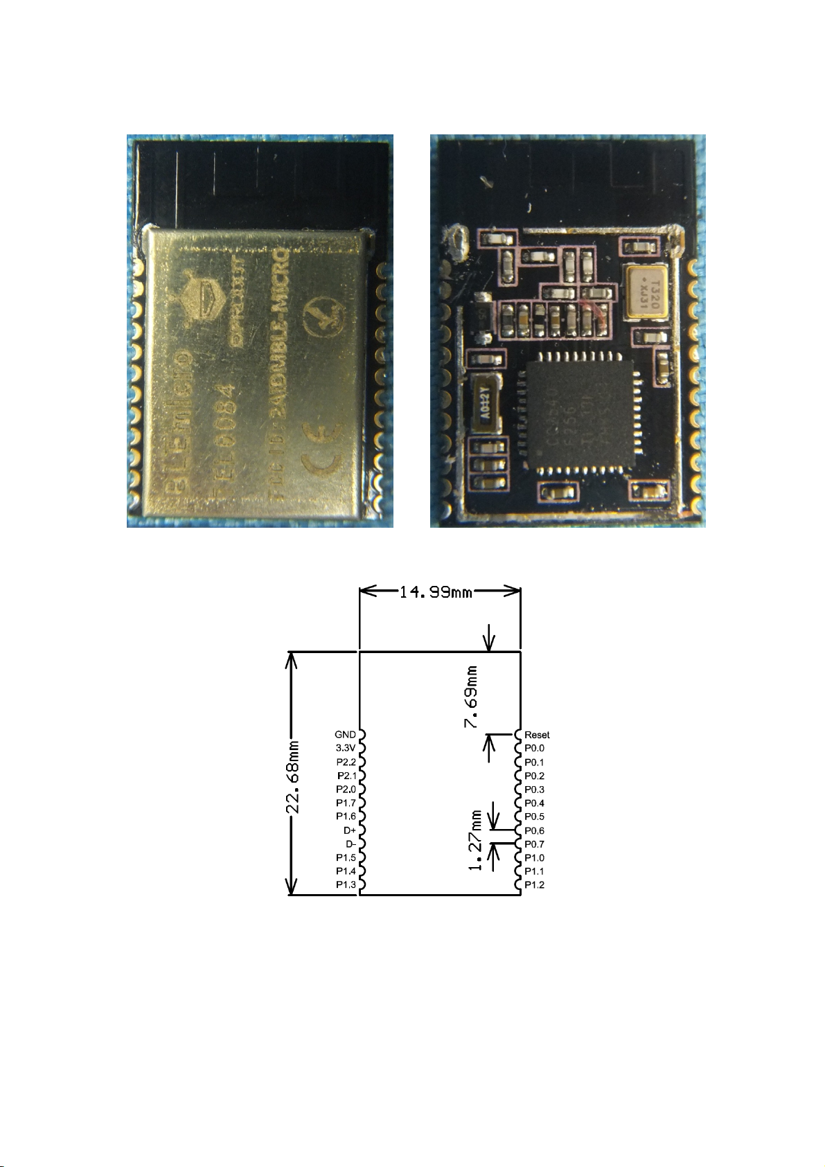
2. HARDWARE INTRODUCTION
Module appearance figure
Note: module: 22.68X14.99mm, Pin spacing: 1.27mm
Pin definition and dimension
2

3. Typical application circuit diagram
The module is limited to OEM installation ONLY
The OEM integrator is responsible for ensuring that the end-user has no manual instruction to remove
or install module.
The module is limited to installation in mobile or fixed application.
This equipment should be installed and operated with a minimum distance 20cm between the radiator
and your body
The separate approval is required for all other operating configuration, including portable
configuration with respect to Part 2.1093 and different antenna configurations.
4. FCC Statement:
This device complies with Part 15 of the FCC Rules. Operation is subject to the following two
conditions:
(1) This device may not cause harmful interference, and
(2) This device must accept any interference received, including interference that may cause undesired
operation.
Please take attention that changes or modification not expressly approved by the party responsible for
compliance could void the user’s authority to operate the equipment.
Note: This product has been tested and found to comply with the limits for a Class B digital device,
pursuant to Part 15 of the FCC Rules. These limits are designed to provide reasonable protection
against harmful interference in a residential installation. This product generates, uses, and can radiate
radio frequency energy and, if not installed and used in accordance with the instructions, may cause
harmful interference to radio communications. However, there is no guarantee that interference will
not occur in a particular installation. If this product does cause harmful interference to radio or
television reception, which can be determined by turning the equipment off and on, the user is
encouraged to try to correct the interference by one or more of the following measures:
—Reorient or relocate the receiving antenna.
—Increase the separation between the equipment and receiver.
—Connect the equipment into an outlet on a circuit different from that to which the receiver is
3

connected.
—Consult the dealer or an experienced radio/TV technician for help.
When the FCC identification number is not visible when the module is installed inside another device,
then the outside of the device into which the module is installed must also display a label referring to
the enclosed module. This exterior label can use wording such as the following: “Contains FCC ID:
2AIDMBLE-MICRO: or FCC ID: 2AIDMBLE-MICRO” and the information should be also contained in the
devices’ user manual
4
 Loading...