

Lierda Science &
Technology Group
Securities
Securities
Securities
Securities Code
Code
Code
Code
IoT
Interconnection,
IoT
Interconnection,
IoT
IoT Interconnection,
Interconnection, Smart
Smart
Smart
Smart Life
Life
Life
Life
Product
Product
Product
Product Name:
Name:
Name:
Name: E66
LSD4BT-E66
LSD4BT-E66
LSD4BT-E66
LSD4BT-E66 Series
User
User
User
User Manual
Lierda Science & Technology Group
E66
Standard
E66
Standard
E66 Standard
Standard Module
Manual
Manual
Manual
Module
Module
Module (PCB
Series
Series
Series
(PCB
(PCB
(PCB Antenna)
Antenna)
Antenna)
Antenna)
Product
Product
Product
Product Model:
File
File
File
File Version:
Model:
Model:
Model: LSD4BT-E66
Version:
Version:
Version: Rev0
LSD4BT-E66
LSD4BT-E66
LSD4BT-E66
Rev0
Rev0
Rev0 4
4
4
4
Page1of
18

Lierda Science &
Technology Group
Securities
Securities
Securities
Securities Code
Code
Code
Code
IoT
Interconnection,
IoT
Interconnection,
IoT
IoT Interconnection,
Interconnection, Smart
Smart
Smart
Smart Life
Life
Life
Life
Serial
Revision Log Revised by
No.
1 Initial version
Update the communication distance of the
module, and add the power consumption
2
data under different connection and
broadcast intervals
Correct the working parameters of the
module, the transmittance state and the
basic frequency of CPU, distinguish the
3
different TRX current of the module in the
ACTIVE mode and in the SLEEP mode,
Revision
Revision
Revision
Revision History
History
History
History
Wang
Hongyang
Wang
Hongyang
Lierda Science & Technology Group
Wang
Hongyang
Reviewed
by
Sun
Xiangtao
Sun
Xiangtao
Sun
Xiangtao
File
Version
Rev01
Rev02
Rev03
Revision
Date
May 31,
2018
October
11, 2018
December
11, 2018
and add the power consumption data under
more time intervals
4 Add Module Authentication information
Page2of
Wang
Hongyang
18
Sun
Xiangtao
March
Rev0 4
1,2019

Lierda Science &
Technology Group
Securities
Securities
Securities
Securities Code
Code
Code
Code
Contents
Contents
Contents
Contents
IoT
Interconnection,
IoT
Interconnection,
IoT
IoT Interconnection,
Interconnection, Smart
Smart
Smart
Smart Life
Life
Life
Life
Chapter
Chapter
Chapter
Chapter 1
1
Overview
1
Overview
1 Overview
Overview ...................................................................................................................................... 4
1.1 Functional Characteristics of Module ............................................................................................... 4
1.2 Application Occasions ...................................................................................................................... 4
Chapter
Chapter
Chapter
Chapter 2
Chapter
Chapter
Chapter
Chapter 3
2
Specification
2
Specification
2 Specification
Specification &
3
Hardware
3
Hardware
3 Hardware
Hardware Layout
Layout
Layout
Layout and
&
Parameters
&
Parameters
& Parameters
Parameters ....................................................................................................... 4
and
Interface
and
Interface
and Interface
Interface Description
Description
Description
Description ........................................................................... 7
3.1 Dimensions ....................................................................................................................................... 7
3.2 Interface Description ......................................................................................................................... 8
3.3 Module Authentication ....................................................................................................................10
Chapter
Chapter
Chapter
Chapter 4
4
Application
4
Application
4 Application
Application Instructions
Instructions
Instructions
Instructions ........................................................................................................... 1 1
Lierda Science & Technology Group
4.1 Notices to Typical Application ........................................................................................................ 1 1
Chapter
Chapter
Chapter
Chapter 5
5
Production
5
Production
5 Production
Production Guidance
Guidance
Guidance
Guidance ................................................................................................................ 1 3
5.1 Production Guide ............................................................................................................................ 1 3
5.2 Requirements on Positions of Module on Backplane ..................................................................... 1 4
5.3 Opening Design of Steel Mesh ....................................................................................................... 1 4
5.4 Standard Operation Procedure (SOP) for Reflow ........................................................................... 1 5
Chapter
Chapter
Chapter
Chapter 6
6
Product
6
Product
6 Product
Product Package
Package
Package
Package ....................................................................................................................... 1 6
6.1 Packaging Method .......................................................................................................................... 1 6
6.2 Strip Size ......................................................................................................................................... 1 6
6.3 Product Direction ............................................................................................................................ 1 6
Reminder
Reminder
Reminder
Reminder ..................................................................................................................................................... 1 7
Page3of
18

Lierda Science &
Technology Group
Securities
Securities
Securities
Securities Code
Code
Code
Code
IoT
Interconnection,
IoT
Interconnection,
IoT
IoT Interconnection,
Interconnection, Smart
Smart
Smart
Smart Life
Life
Life
Life
Chapter
Chapter
Chapter
Chapter 1
1
Overview
1
Overview
1 Overview
Overview
E66 series of Bluetooth module is a low-energy and high-performance Bluetooth module which is
researched and developed based on the low-energy and high-performance Bluetooth SOC chip. The
module adopts the stamp hole-type interface, and is pre-reserved with two optional interfaces: PCB
antenna and external antenna; the module is in small size, is led out by full port, is convenient to use, and
can help you reduce the investment in software and hardware, and easily realize the development of
Bluetooth application.
Table 1-1 Model Description
Model Description
PCB antenna. This model does not include software. For the product
LSD4BT-E66
Lierda Science & Technology Group
with software, please communicate with the salesman over the specific
model, MPQ and other information
1.1
Functional
1.1
Functional
1.1
1.1 Functional
Functional Characteristics
Characteristics
Characteristics
Characteristics of
of
Module
of
Module
of Module
Module
� Working voltage: 1.6~3.6V
Designed frequency: 2402MHz~2480MHz
�
Transmittance power: Max 7dBm
�
Ultra-high receiving sensitivity: -93 ± 1dBm
�
Ultra-far effective communication distance: 30m@0dBm
�
1.2
Application
1.2
Application
1.2
1.2 Application
Application Occasions
�
�
�
Chapter
Chapter
Chapter
Chapter 2
Main
Main
Main
Main Parameters
Smartphone and tablet peripherals
Wireless wearable Bluetooth equipment
Intelligent light control, smart home, smart city
2
Specification
2
Specification
2 Specification
Specification &
Parameters
Parameters
Parameters Performance
Occasions
Occasions
Occasions
&
Parameters
&
Parameters
& Parameters
Parameters
Table 2-1 Limit Parameters of the Product
Performance
Performance
Performance Remarks
Remarks
Remarks
Remarks
Page4of
18

Lierda Science &
Technology Group
Securities
Securities
Securities
Securities Code
Code
Code
Code
IoT
Interconnection,
IoT
Interconnection,
IoT
IoT Interconnection,
Interconnection, Smart
Smart
Smart
Smart Life
Life
Life
Life
Minimum
Minimum
Minimum
Minimum Value
Value
Value
Value Maximum
Maximum
Maximum
Maximum Value
Power supply voltage (V) 1.6 3.6
Working temperature ( ℃ ) -40 +85
ESD (KV) 3 / All PINS, HBM MADE
Table 2-2 Working Parameters of the Module @ 25 ℃
Performance
Performance
Performance
Performance
Main
Parameters
Main
Parameters
Main
Main Parameters
Parameters
Minimum
Minimum
Minimum
Minimum
Value
Value
Value
Value
Typical
Typical
Typical
Typical
Value
Value
Value
Value
Maximum
Maximum
Maximum
Maximum
Value
Value
Value
Value
Working voltage (V) 1.6 3.3 3.6
Lierda Science & Technology Group
Working temperature
-40 / +85 Normal communication
( ℃ )
Value
Value
Value
Remarks
Remarks
Remarks
Remarks
The ripple of the power supply
requires the peak value to be
within 30mV
Working frequency
2402 / 2480 ISM frequency band
band (MHz)
Number of channels / 40 /
Transmittance state
(mA)
/ 10.5 /
ACTIVE
Power
Consumption
Transmittance state
(mA)
/ 6.58 /
SLEEP
Receiving state (mA)
/ 10.3 /
ACTIVE
Standard number of channels
under BLE Agreement
2402MHz, 0dBm@16M The
whole CPU works
2402MHz, 0dBm@16M Only
the RF part of the CPU works
2402MHz@16M The whole
CPU works
Page5of
18

Lierda Science &
Technology Group
Securities
Securities
Securities
Securities Code
Code
Code
Code
IoT
Interconnection,
IoT
Interconnection,
IoT
IoT Interconnection,
Interconnection, Smart
Smart
Smart
Smart Life
Life
Life
Life
Receiving state (mA)
2402MHz@16M Only the RF
/ 6.09 /
SLEEP
part of the CPU works
SLEEP ( μ A) / 2 /
Transmittance power (dBm) -15 / 7 Software configurable
PER<30.8%
Receiving sensitivity (dBm) / -93 /
(BER<0.1%)
Communication protocol BLE4.0/4.2
Interface Type 1.27mm of spacing, 3-sided stamp hole
Chip
Communication distance
1
30m@0dBm
configuration@0dBm
Lierda Science & Technology Group
1. “ Communication distance ” is affected by the measuring environment, air humidity and other
factors around. The distance is measured via the communication between the mobile phone and the module,
and is only for reference.
Table 2-3 Power Consumption of the Module under Different Broadcast Intervals
Mode
Mode
Mode
Mode Average
Average
Average
Average Power
0dBm
Broadcast
mode
Power
Power
Power Consumption
Consumption
Consumption
Consumption (
(
μ
A)
(
μ
A)
( μ
μ A)
A) Broadcast
122.3 100
60.8 200
29.4 500
22.2 700
19.6 1000
12.1 2000
8.1 3000
6.7 5000
5.3 7000
4.4 10000
Broadcast
Broadcast
Broadcast Interval
Interval
Interval
Interval (ms)
(ms)
(ms)
(ms)
Page6of
18

Lierda Science &
Technology Group
Securities
Securities
Securities
Securities Code
Code
Code
Code
IoT
Interconnection,
IoT
Interconnection,
IoT
IoT Interconnection,
Interconnection, Smart
Table 2-4 Power Consumption of the Module under Different Connection Intervals
Smart
Smart
Smart Life
Life
Life
Life
Mode
Mode
Mode
Mode Average
Average
Average
Average Power
Power
Power
Power Consumption
Consumption
Consumption
Consumption (
(
μ
A)
(
μ
A)
( μ
μ A)
A) Connection
Connection
Connection
Connection Interval
Interval
Interval
Interval (ms)
(ms)
(ms)
(ms)
61.1 100
31.1 200
16.3 500
0dBm
14.7 700
Connection
12.1 1000
mode
8.9 2000
7.2 3000
6.6 4000
Lierda Science & Technology Group
Note: The power consumption data tested in the connection mode is tested via the non-data communication
between the mobile phone and the module.
Chapter
Chapter
Chapter
Chapter 3
3
Hardware
3
Hardware
3 Hardware
Hardware Layout
3.1
Dimensions
3.1
Dimensions
3.1
3.1 Dimensions
Dimensions
Layout
Layout
Layout and
and
Interface
and
Interface
and Interface
Interface Description
Description
Description
Description
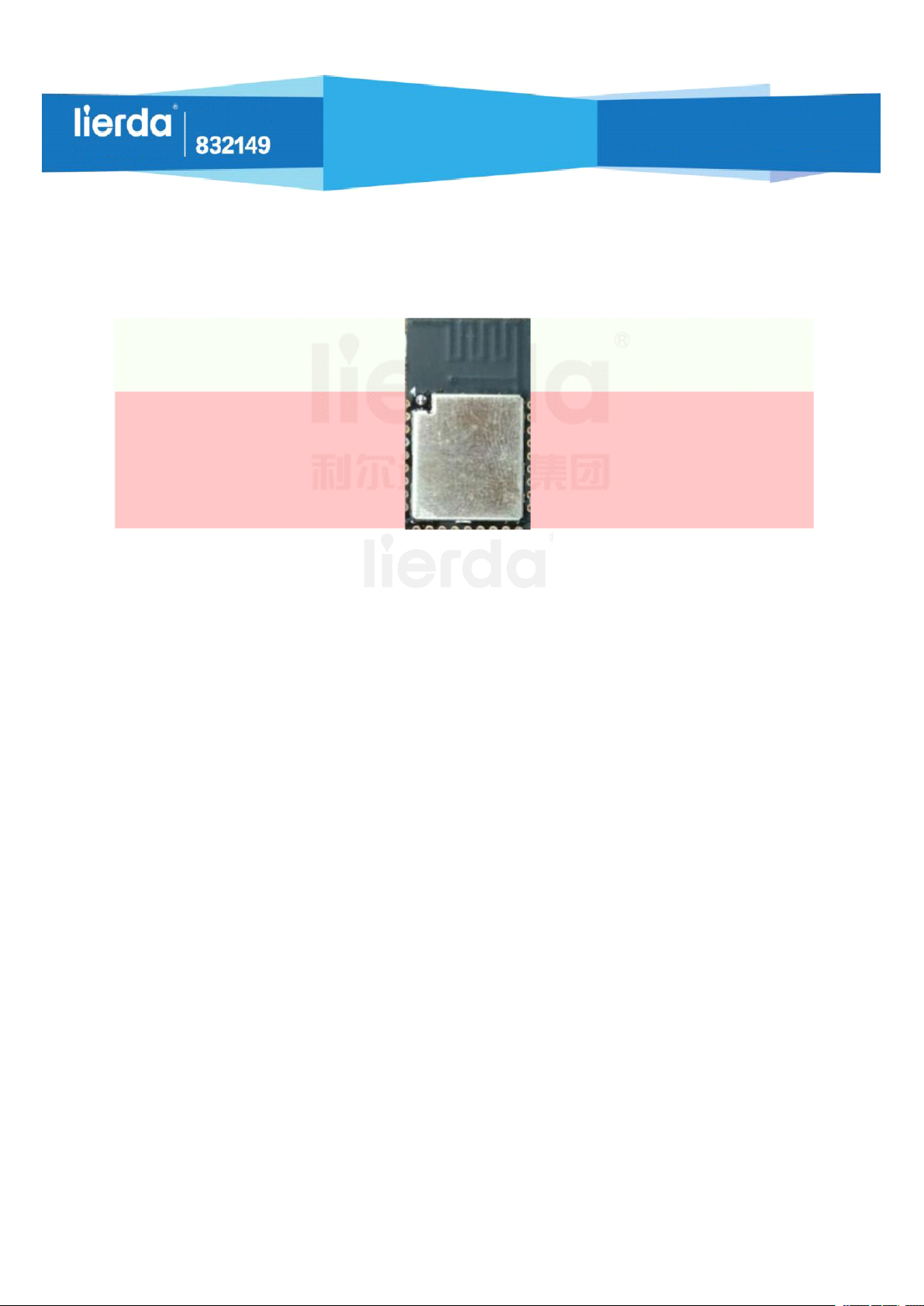
The physical view of LSD4BT-E66 is as shown in the following Fig. 3-1:
Fig. 3-1 Physical View of LSD4BT-E66 Series of Module
When this product is designed, the tantalum capacitors and PCBs have optional material models. On
Page7of
18

Lierda Science &
Technology Group
Securities
Securities
Securities
Securities Code
Code
Code
Code
IoT
Interconnection,
IoT
Interconnection,
IoT
IoT Interconnection,
Interconnection, Smart
the premise that the performance requirements are met, the appearance color may be different, and the
actual product shall prevail. The main materials (main chips, crystal oscillators, etc.) do not have any
substitutional models. Any change will be notified in advance.
The dimensions of the module LSD4BT-E66 are as shown in the following Fig. 3-2:
Smart
Smart
Smart Life
Life
Life
Life
Lierda Science & Technology Group
Fig. 3-2 Dimension Diagram of LSD4BT-E66 Series of Module
The dimensional tolerance which is not marked in the figure is subject to the standard GB/T1804-m.
3.2
Interface
3.2
Interface
3.2
3.2 Interface
Interface Description
The following figure shows the serial number of the pins of the module and describes the
corresponding pins:
Description
Description
Description
Page8of
18

Lierda Science &
Technology Group
Securities
Securities
Securities
Securities Code
Code
Code
Code
IoT
Interconnection,
IoT
Interconnection,
IoT
IoT Interconnection,
Interconnection, Smart
Smart
Smart
Smart Life
Life
Life
Life
Lierda Science & Technology Group
Table 3-1 Functional Description of Pins of LSD4BT-E66 Series of Module
Module
Chip Pin Name Function Remarks
Pin
1 / NC
2 41 GND
3 23 P3/PADC GPIO
4 24 P4/PADC GPIO
5 25 P5/PADC GPIO
6 26 P6/PADC GPIO
7 27 P9 GPIO
8 28 P10 GPIO
Not connected
Grounded
9 29 P11 GPIO
10 18 VBAT
Page9of
18
Power supply

Lierda Science &
Technology Group
Securities
Securities
Securities
Securities Code
Code
Code
Code
IoT
Interconnection,
IoT
Interconnection,
IoT
IoT Interconnection,
Interconnection, Smart
Smart
Smart
Smart Life
Life
Life
Life
11 41 GND
12 32 RSTN
13 6 SWCLK
14 7 SWD
Grounded
Reset
Programmed
Programmed
15 34 P15 GPIO
16 35 P16 GPIO
17 36 P17 GPIO
18 37 P18 GPIO
19 38 P19 GPIO
20 39 P20 GPIO
Lierda Science & Technology Group
21 1 P24 GPIO
22 2 P25 GPIO
23 3 P26 GPIO
24 4 P27 GPIO
25 5 P28 GPIO
26 41 GND
27 10 ANT
Grounded
External
antenna
3.3
Module
3.3
Module
3.3
3.3 Module
Module Authentication
Authentication
Authentication
Authentication
This module has been certified by SRRC (China) and FCC (United States). CMIIT ID number is
xxxxxxxx, and FCC ID number is 2AOFDLSD4BT-E66A .
Three display modes of CMIIT ID and FCC ID are provided. The first shield laser scheme is
defaulted.
1.Shield shield laser: display module product serial number, CMIIT ID, FCC ID, RoHS logo, lierda
Page
10
18
of

Lierda Science &
Technology Group
Securities
Securities
Securities
Securities Code
Code
Code
Code
registered trademark, CE certification logo, etc., with shield as the specific criterion;
2.Back label: display module product serial number, CMIIT ID, FCC ID, module P/N, lierda
registered trademark, etc, specific to the manufactured product;
IoT
Interconnection,
IoT
Interconnection,
IoT
IoT Interconnection,
Interconnection, Smart
Smart
Smart
Smart Life
Life
Life
Life
Fig. 3- 3 Back label
3.Display by the terminal device : The SRRC ID, FCC ID, etc, can be referenced by the terminal
Lierda Science & Technology Group
device according to relevant standards.
Chapter
Chapter
Chapter
Chapter 4
4
Application
4
Application
4 Application
Application Instructions
4.1
Notices
4.1
Notices
4.1
4.1 Notices
Notices to
to
Typical
to
Typical
to Typical
Typical Application
Instructions
Instructions
Instructions
Application
Application
Application
1. Power Supply
It is suggested supplying power to the module with the DC regulated power supply. The ripple
coefficient of the power supply shall be smaller as possible, and the module shall be grounded reliably.
Please pay attention to the correct connection of the positive and negative poles of the power supply,
because reverse connection may lead to the permanent damage of the module;
2. Antenna Selection
2.1 PCB Antenna
The module is an on-board PCB antenna. During the layout of the board, please make sure the area
right below the antenna is completely clear, as shown in the following figure. The red part is the user’s
backplane area or the copper-clad area, the grey part is the clear area of the antenna of the user’s backplane,
and the boundary point of the clear area is the upper edge of the shielding cover. Make sure there is no any
11
Page
18
of
Lierda Science &
Technology Group
Securities
Securities
Securities
Securities Code
Code
Code
Code
IoT
Interconnection,
IoT
Interconnection,
IoT
IoT Interconnection,
Interconnection, Smart
metal in 360 degrees around the antenna; otherwise, the radiation efficiency of the antenna will be affected,
and the communication distance will be greatly affected.
Fig. 4-1 Description of Clear Area of Antenna
Smart
Smart
Smart Life
Life
Life
Life
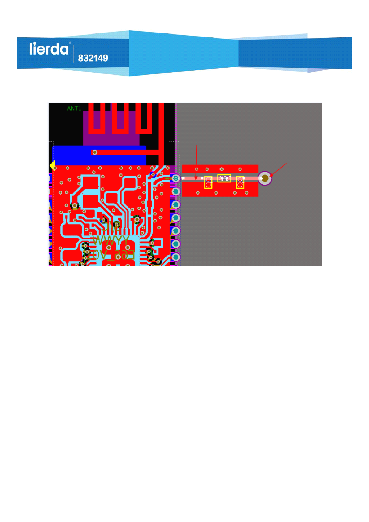
2.2 External Antenna
The module is connected with the external antenna through the stamp hole. It is suggested
Lierda Science & Technology Group
pre-reserving π matched network on the backplane. The external interface can be SMA or IPEX. As shown
in the following figure 4-2, for the RF wiring of the highlight part, it needs to lay the 50ohm impedance
line; the relationship between the width of the 50ohm impedance line, wiring and the copper-clad spacing,
board thickness is as shown in Figure 4-3.
Page
12
18
of
Lierda Science &
Technology Group
Securities
Securities
Securities
Securities Code
Code
Code
Code
IoT
Interconnection,
IoT
Interconnection,
IoT
IoT Interconnection,
Interconnection, Smart
Smart
Smart
Smart Life
Life
Life
Life
50ohm impedance control
IPEX block or SMA
Lierda Science & Technology Group
Fig. 4-2 Recommended Circuit of External Antenna
Recommended values of FR4 dual panel
(H=Board thickness, W=Line width, D=Spacing between wiring and copper-clad):
connector
H=1.0mm, W=0.8mm, D=0.2mm
H=1.0mm, W=1.0mm, D=0.254mm (Recommended)
H=1.2mm, W=1.0mm, D=0.2mm (Recommended)
H=1.6mm, W=1.0mm, D=0.2mm (Recommended)
Fig. 4-3 Recommended Wiring of 50ohm Impedance Line
3. Electrostatic Notices
The user shall pay attention to the electrostatic requirements (as shown in Table 2-1) of the product
when in design, and add the electrostatic prevention measures when designing the end products.
Chapter
Chapter
Chapter
Chapter 5
5
Production
5
Production
5 Production
Production Guidance
5.1
Production
5.1
Production
5.1
5.1 Production
Production Guide
Guidance
Guidance
Guidance
Guide
Guide
Guide
Page
13
18
of

Lierda Science &
Technology Group
Securities
Securities
Securities
Securities Code
Code
Code
Code
IoT
Interconnection,
IoT
Interconnection,
IoT
IoT Interconnection,
Interconnection, Smart
It is suggested the stamp hole packaging module mounted by an SMT machine, and the mounting
shall be finished within 24 hours after unpacking. Otherwise, its need to repackage by vacuumizing, so as
to prevent poor mounting effect due to damp.
If the package includes a humidity indicator card, it is suggested judging if the module needs to be
baked according to the indication of the humidity indicator card. The baking conditions are as follows:
Baking temperature: 125 ℃ ± 5 ℃ ;
The alarm temperature is set to be 130 ℃ ;
SMT mounting can be carried out after the temperature cools down to be <36 ℃ under natural
conditions;
Smart
Smart
Smart Life
Life
Life
Life
If the product is unpacked for over 3 months, please pay special attention if the product is affected
with damp, because the PCB gold immersion process may lead to the oxidation of the land after more than
Lierda Science & Technology Group
3 months, and may lead to such problems as false welding and missing welding during the mounting
process.
In order to ensure the pass rate of reflow, it is suggested picking 10% of products for visual inspection
and AOI detection in the first time of mounting, so as to ensure the reasonableness of the furnace
temperature, device absorption method and placement method;
Operators at all stations must wear the anti-electrostatic gloves during the whole production process;
5.2
Requirements
5.2
Requirements
5.2
5.2 Requirements
Requirements on
on
Positions
on
Positions
on Positions
Positions of
of
Module
of
Module
of Module
Module on
on
Backplane
on
Backplane
on Backplane
Backplane
It is suggested the green oil thickness at the module position of the backplane be less than 0.02mm, so
as to prevent the phenomenon that the green oil is too thick, the module is blocked up and cannot be
effectively contacted with solder paste, and the welding quality is affected.
In addition, please do not place other devices within 2mm around the module position on the interface
board, so as to ensure the convenience for repairing the module.
5.3
Opening
5.3
Opening
5.3
5.3 Opening
Opening Design
Design
Design
Design of
of
Steel
of
Steel
of Steel
Steel Mesh
Mesh
Mesh
Mesh
The thickness of the steel mesh on the backplane shall be selected by comprehensively considering
the packaging type of the devices in the board, and special attention shall be paid to the following
14
Page
18
of
Lierda Science &
Technology Group
requirements:
The land position of the module can be locally thickened to 0.15~0.20mm, so as to prevent void
solder;
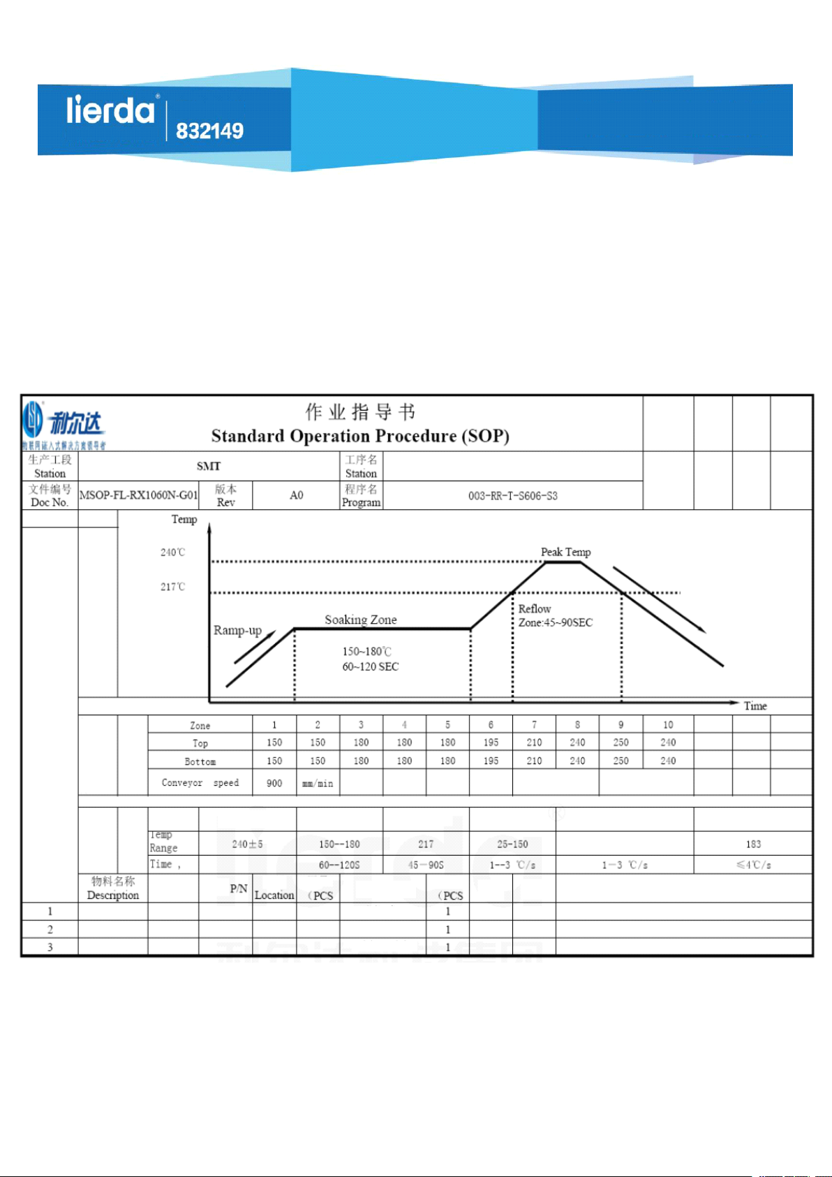
5.4
5.4
5.4
5.4 Standard
Note: This SOP is only applicable to lead-free operation, and only for reference.
Securities
Securities
Securities
Securities Code
Standard
Standard
Standard Operation
Code
Code
Code
Operation
Operation
Operation Procedure
Procedure
Procedure
Procedure (SOP)
(SOP)
(SOP)
(SOP) for
for
Reflow
for
Reflow
for Reflow
Reflow
IoT
Interconnection,
IoT
Interconnection,
IoT
IoT Interconnection,
Interconnection, Smart
Approved
by
Reflow
Smart
Smart
Smart Life
Gener
Revie
ated
wed
by
by
Life
Life
Life
Gener
ation
Date
Operation
Items
Curve
Chart
Tempe
rature
Zone
Param
eters
Curve
Param
eters
Specificat
ion
Peak temperature
Material
No.
Lierda Science & Technology Group
Soaking
temperature
位号
Used
Amount
Tool/Equipment
Thermometer
Thermometric plate
High temperature-resistant
gloves
Tin fusion
temperature
Slope of
increase
Used
Amount
No Date
Slope of reflow
Revision Contents
Slope of cooling
Page
15
18
of

Lierda Science &
Technology Group
Securities
Securities
Securities
Securities Code
Code
Code
Code
IoT
Interconnection,
IoT
Interconnection,
IoT
IoT Interconnection,
Interconnection, Smart
Smart
Smart
Smart Life
Life
Life
Life
Chapter
Chapter
Chapter
Chapter 6
6
Product
6
Product
6 Product
Product Package
6.1
Packaging
6.1
Packaging
6.1
6.1 Packaging
Packaging Method
Package
Package
Package
Method
Method
Method
■ Tape □ Foam □ Electrostatic bag
6.2
Strip
6.2
6.2
6.2 Strip
Size
Strip
Size
Strip Size
Size
Lierda Science & Technology Group
Technical
Requirement 1
Reference Size
Technical Requirements:
1. The accumulative error of every 10 driving holes shall be within ± 0.2;
2. The side bend within 250MM must be no more than 1;
3. Material of carrier tape: Black PS, thickness: 0.30 ± 0.05;
4. The surface impedance is from 106to 1011ohm;
6.3
Product
6.3
Product
6.3
6.3 Product
Product Direction
5. Each roll is packed by a 21m 13
elements
6. A0 and B0 shall be measured at 0.3mm upwards at the bottommost of the
inner side of the die cavity, and K0 refers to the inner depth. The unmarked R
angle is 0.3
7. The product meets the standard EIA-481;
8. The product is required to meet “ ROHS ” ;
Direction
Direction
Direction
’’
plastic tray, and can contain 1000 Pcs
Client No.: LSD4BT-E66ASTD001
Ver
sion
Revision Contents
The placement direction of the tape packaging module is as shown in the following figure:
16
Page
18
of
Date

Lierda Science &
Technology Group
Securities
Securities
Securities
Securities Code
Code
Code
Code
Protecting tape
IoT
Interconnection,
IoT
Interconnection,
IoT
IoT Interconnection,
Interconnection, Smart
Smart
Smart
Smart Life
Life
Life
Life
Carrier tape rubber wheel
Reminder
Reminder
Reminder
Reminder
Lierda Science & Technology Group
Product information label
Carrier tape
Oval hole
Cover tape
Round hole
Discharge direction
Welcome to use the products of Lierda Science & Technology Group Co., Ltd.. Prior to the use of our
Depression
products, please first read this reminder; if you have started to use the Instructions, you will be considered
as having read and accepted the reminder.
Lierda Science & Technology Group Co., Ltd. reserves the final interpretation and revision rights
17
Page
18
of

Lierda Science &
Technology Group
Securities
Securities
Securities
Securities Code
Code
Code
Code
over all attached materials, and any modification of them will not be further notified.
IoT
Interconnection,
IoT
Interconnection,
IoT
IoT Interconnection,
Interconnection, Smart
Smart
Smart
Smart Life
Life
Life
Life
Lierda Science & Technology Group
Page
18
18
of

FCC Statement:
This device complies with part 15 of the FCC rules Operation is subject to the following two
conditions: (1) this device may not cause harmful interference, and (2) this device must accept
any interference received, including interference that may cause undesired operation.
NOTE: The manufacturer is not responsible for any radio or TV interference caused by
unauthorized modifications to this equipment. Such modifications could void the user’s authority
to operate the equipment.
NOTE: This equipment has been tested and found to comply with the limits for a Class B digital
device, pursuant to part 15 of the FCC Rules. These limits are designed to provide reasonable
protection against harmful interference in a residential installation. This equipment generates
uses and can radiate radio frequency energy and, if not installed and used in accordance with the
instructions, may cause harmful interference to radio communications. However, there is no
guarantee that interference will not occur in a particular installation. If this equipment does cause
harmful interference to radio or television reception, which can be determined by turning the
equipment off and on, the user is encouraged to try to correct the interference by one or more of
the following measures:
- Reorient or relocate the receiving antenna.
- Increase the separation between the equipment and receiver.
-Connect the equipment into an outlet on a circuit different from that to which the receiver is
connected.
-Consult the dealer or an experienced radio/TV technician for help
- This device and its antenna(s) must not be co-located or operating in conjunction with any other
antenna or transmitter.
RF Exposure Information and Statement :
This equipment complies with FCC radiation exposure limits set forth for an uncontrolled
environment. This equipment should be installed and operated with minimum distance of 20 cm
between the radiator and your body. This transmitter must not be co-located or operating in
conjunction with any other antenna or transmitter
Instructions to the OEM/Integrator:
This module has been granted modular approval for mobile applications. OEM integrators for
host products may use the module in their final products without additional FCC certification if
they meet the following conditions. Otherwise, Additional FCC approvals must be obtained.

The OEM must comply with the FCC labeling requirements. If the module’s label is not
visible when installed, then an additional permanent label must be applied on the outside of
the finished product which states: ”Contains transmitter module FCC
ID:2AOFDLSD4BT-E66A,Additionally, the following statement should be included on the label
and in the final product’s user manual:
“This device complies with Part 15 of the FCC Rules. Operation is subject to the following
two conditions: (1) This device may not cause harmful interferences, and (2) this device
must accept any interference received, including interference that may cause undesired
operation.”
The user’s manual for the host product must clearly indicate the operating requirements and
conditions that must be observed to ensure compliance with current FCC RF exposure
guidelines.
The final host / module combination may also need to be evaluated against the FCC Part 15B
criteria for unintentional radiators in order to be properly authorized for operation as a Part
15 digital device.
This Module is full modular approval, it is limited to OEM installation ONLY.
The module is limited to installation in mobile application.
A separate approval is required for all other operating configurations, including portable
configurations with respect to Part 2.1093 and difference antenna configurations.
The OEM integrator is responsible for ensuring that the end-user has no manual instruction
to remove or install module.
The Grantee will provide guidance to the Host Manufacturer for compliance with the Part
15B requirements if requested.
 Loading...