

Parts
Package include
Emitter
Receiver(Headphone)
Instruction Manual
Audio cable
Audio Transform cable
1
1
1
1
1
Installation
Installing the receiver:
Insert two AAA batteries into the battery compartmentaccording to the + andpolarity. tune the power On/Off of the receiver, then the receiver indicator will
brighten.
Installing the emitter:
Insert two AAA batteries into the battery compartment according to the + and
polarity
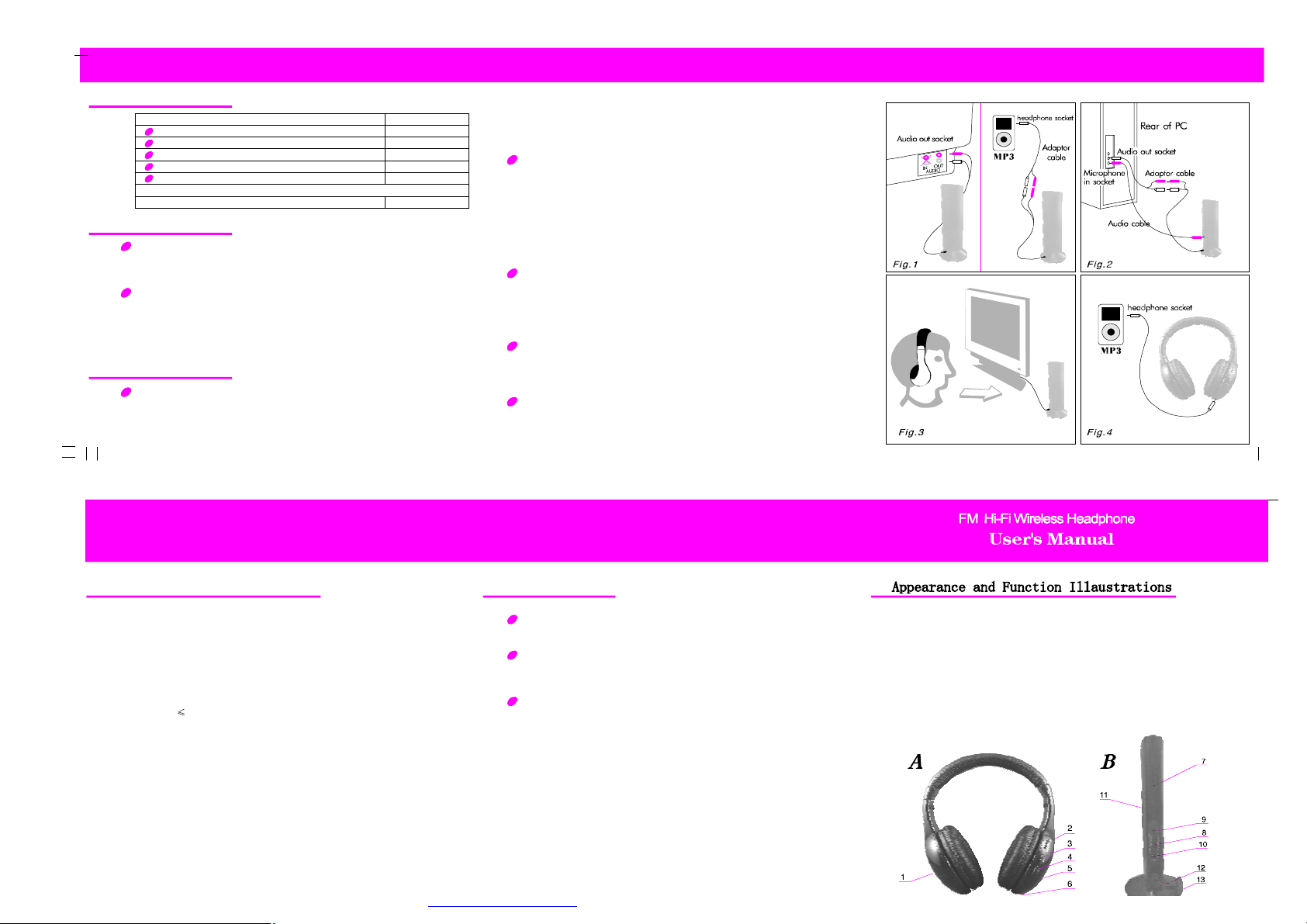
(3.0V DC).Insertaudio plug of the emitter into AUDIO-OUT socket of audio
source (such as TV set audio device PCDVD playerCD playerMP3
playeretc.). Please see Fig.1, Fig.2, Fig.3, Fig.4 ( Note: locate the emitter at
a highposition in order to achieve bestreception effect)
、
、
、、、、
-
Operation
Wireless headphone
()()1Please see Fig.1, Insert the emitter audio cable into the AUDIO-OUT socket
of theelectronic device or headphone socket, and move the function switch of the
emitter to the “ON” position, then the emitter indicator shine.
2Built in the battery on the emitter and the receiver, draw the function switch
to the “WIRELESS” position, the receiver indicator brighten. Put the volume
control to asuitable position, then adjust the tiny modulation on the emitter till
getting abest effect (largest sound and clearest).
Wireless net audio chat
()
1Connect the emitter audio cable to the adaptor cable (optional) (see Fig.2),
and insert the other end of the adaptor cable into the audio out socket of the PC,
then insert one end of the audio cable (optional) into the microphone socket (MIC)
on theemitter, and insert the other end into the microphone in socket of the PC.
()
2Turn on the power switch of the emitter, then the indicator brighten, putthe
out-built MIC forward yourself and keep away with the distance of 0.5M.
()
3open your chat tool and tune the power On/Off button , then the indicator of the
headphone brighten. Adjust the volume to the suitable position, then headphone can
receive the sound via the SKYPE/MSN/QQ from your friends in the other end.
Listen to the radio
The receiver can be used separately as an FM radio. First draw the function
switchto the “FM” position, and then press the “RESET” once, then press the
“SCAN”key in turn to search a higher range and lock one radio channel; when
the highest range is reached, press “RESET” key, and the frequency returns to
the lowest range. Press “SCAN” key again, and the receiver will search the
radio channels from thelow range again.
Wired Headphone (without batteries)
Insert one end of the audio cable (optional) into the audio socket of the receiver
(see Fig.4), and insert the other end into the headphone socket of the electronic
devices, such as MP3 playerVCD playerDVD player etc., and then the unit
can be used as a wired headphone.
Wireless monitoring
(1) Turn on the emitter by tuning power switch . Then the emitter indicator brighten up.
(2)Turn on the receiver by tuning Volume control button. Then the receiver indicator
brighten up.
(3) Place the emitter with the wards.
Press RESET button, then press SCAN button to SCAN sound from wards automatically.
、、、
(see Fig.3)
MIC
MIC
Technical Specifications
Emitter
Emission frequency: 88.1MHz
Modulation mode: FM
Emission distance: 30M (with no interference)
Power supply: 2xAAA batteries .
Receiver(headphone)
Frequency range: 88.1MHz for wireless headphone and 87-108MHz for FM radio.
ReceptionMode: FM
Distortion:
PowerSupply2xAAAbatteries
2%
:
Notes
To achieve best reception spread out emitter audio cable of the emitter
or locate the emitter at a higher position.(the emitter audio cable can
also be used as antenna).
If the sound is distorted or too strong, adjust the volume of the signal
source (TV setVCDplayer DVD playerPCMP3 walkman
etc.) To a lower level, and reception performance may be improved.
Replace the batteries if you are having the following problems
The emitter indicator becomes dim.
1)
The receiver reception is poor.
2)
The volume becomes weak and the sound is distored.
3)
、、、、、、
AReceiver
1.Battery compartment cover
2.Volume control and power button
(ON/OFF)
3.Scan key(SCAN)
4.Reset key(RESET)
5.Power indicator
6 .Audio socket
BEmitter
7Power indicator (Front )
.
8.Power and function switch
9.Microphone socket (MIC)
10.Vacancy
11.Microphone (MIC)
12.Audio cable of emitter
13.Battery compartment cover (bottom)

FCC ID:INC-66121
This device complies with Part 15 of the FCC Rules. Operation
is subject to the following two conditions: (1) this device may
not cause harmful interference, and (2) this device must accept
any interference received, including interference that may cause
undesired operation.
changes or modifications not expressly approved by the party responsible for compliance
could void the user's authority to operate the equipment.
NOTE: This equipment has been tested and found to comply with the limits for a
Class B digital device, pursuant to Part 15 of the FCC Rules. These limits are
designed to provide reasonable protection against harmful interference in a
residential installation. This equipment generates, uses and can radiate radio
frequency energy and, if not installed and used in accordance with the
instructions, may cause harmful interference to radio communications. However,
there is no guarantee that interference will not occur in a particular installation.
If this equipment does cause harmful interference to radio or television reception,
which can be determined by turning the equipment off and on, the user is
encouraged to try to correct the interference by one or more of the following
measures:
-- Reorient or relocate the receiving antenna.
-- Increase the separation between the equipment and receiver.
-- Connect the equipment into an outlet on a circuit different
from that to which the receiver is connected.
-- Consult the dealer or an experienced radio/TV technician for
help.
 Loading...