

Page 1
INSTRUCTION
INSTRUCTION
INSTRUCTION
INSTRUCTION MANUAL
MANUAL
MANUAL
MANUAL
FOR
FOR
FOR
FOR FSH62832
2.4G
2.4G
2.4G
2.4G 6-channel
FSH62832
FSH62832
FSH62832
6-channel
6-channel
6-channel FHSS
FHSS
FHSS
FHSS Radio
Radio
Radio
Radio control
control
control
control system
system
system
system for
for
Helicopters
for
Helicopters
for Helicopters
Helicopters
FCC
FCC
FCC
FCC ID:
ID:
ID:
ID: A6EZJFSH62832
Page 2

Zhejiang
Zhejiang
Zhejiang
Zhejiang Feishen
Feishen
Feishen
Feishen Vehicle
Contents
Contents
Contents
Contents
Vehicle
Vehicle
Vehicle CO.,
CO.,
CO.,
CO., LTD
LTD
LTD
LTD .
.
.
.
Introduction
Introduction
Introduction
Introduction ………………………………………………………………………………
Usage
Usage
Usage
Usage Precautions
Contents
Contents
Contents
Contents and
Glossary
Glossary
Glossary
Glossary ……………………………………………
FSH62832
FSH62832
FSH62832
FSH62832 equipment
Receiver
Receiver
Receiver
Receiver description
Transmit
Transmit
Transmit
Transmit and
Device
Device
Device
Device connection
LIQUID
LIQUID
LIQUID
LIQUID CHIP
Transmitter
Transmitter
Transmitter
Transmitter battery
Mixing
Mixing
Mixing
Mixing error
Program
Program
Program
Program setting
Precautions
Precautions
Precautions ………………………………………………………………………
and
and
and specifications
description
description
description ……………………………………………………………………
and
and
and receive
connection
connection
connection …………………………………………
CHIP
CHIP
CHIP DISPLAY(LCD)
error
error
error warning
setting
setting
setting ……………………………………………………………………………
MODL Model options function ……………………………………………………
MODL Model options function ………………………………………………………
REST Data reset function ………………………………………………………………
Model name setting ……………………………………………………………………
REVR Servo institution reverse …………………………………………………………
D/R Setting of double ratio and index …………………………………………………
D/R Dual Rates …………………………………………………………………………
EXPO Exponential Settings ……………………………………………………………
EPA
End Point Adjustment ………………………………………………………………
TRIM Trim Settings ……………………………………………………………………
N-TH Normal throttle curve function ……………………………………………
N-PI Normal pitch curve …………………………………………………………
I-TH Idle Up throttle curve function …………………………………………………
I-PI Pitch Curve Idle UP ………………………………………………………………
HOLD Throttle hold function ……………………………………………………………
REVO Revolution Mixing ……………………………………………………………
GYRO Gyro mixing function …………………………………………………………
SWSH Swashplate type selection and Swash AFR ……………………………
Swashplate AFR (Adjustable Function Rate) …………………………………
Technological
Technological
Technological
Technological diagram
FSH62832
FSH62832
FSH62832
FSH62832 other
Coach function ……………………………………………………………………………
Throttle close function ……………………………………………………………………
Adjustable length control sticks ………………………………………………………
Changing Stick Mode ……………………………………………………………………
other
other
other functions
………………………………………………………………………………
………………………………………………………………………………
……………………………………………………………………………… 3
………………………………………………………………………
………………………………………………………………………
……………………………………………………………………… 3
specifications
specifications
specifications ………………………
……………………………………………
……………………………………………
…………………………………………… .
equipment
equipment
equipment interface
receive
receive
receive match
DISPLAY(LCD)
DISPLAY(LCD)
DISPLAY(LCD) and
battery
battery
battery and
warning
warning
warning …………………………………………………………………………
diagram
diagram
diagram ……………………………………………………………………
functions
functions
functions …………………………………………………………………
interface
interface
interface ………………………………………………………
……………………………………………………………………
……………………………………………………………………
…………………………………………………………………… 7
match
match
match ……………………………………………………………
…………………………………………
…………………………………………
………………………………………… .
and
volt
and
volt
and volt
volt ………………………………………………………………
…………………………………………………………………………
…………………………………………………………………………
………………………………………………………………………… 10
……………………………………………………………………………
……………………………………………………………………………
…………………………………………………………………………… 11
……………………………………………………………………
……………………………………………………………………
…………………………………………………………………… 11
…………………………………………………………………………
…………………………………………………………………………
………………………………………………………………………… 13
……………………………………………………………………
……………………………………………………………………
…………………………………………………………………… 15
……………………………………………………………………
……………………………………………………………………
…………………………………………………………………… 24
……………………………………………………………………………
……………………………………………………………………………
…………………………………………………………………………… 25
……………………………………………………………………
……………………………………………………………………
…………………………………………………………………… 25
……………………………………………………………………
……………………………………………………………………
…………………………………………………………………… 25
………………………
………………………
……………………… .
………………………………………………………
………………………………………………………
……………………………………………………… 5
……………………………………………………………
……………………………………………………………
…………………………………………………………… 8
and
program
and
program
and program
program control
………………………………………………………………
………………………………………………………………
……………………………………………………………… 10
……………………………………………………
……………………………………………………
…………………………………………………… 11
………………………………………………………
………………………………………………………
……………………………………………………… 11
………………………………………………………………
………………………………………………………………
……………………………………………………………… 11
…………………………………………………………
…………………………………………………………
………………………………………………………… 12
……………………………………………………………
……………………………………………………………
…………………………………………………………… 13
………………………………………………………………
………………………………………………………………
……………………………………………………………… 14
…………………………………………………………
…………………………………………………………
………………………………………………………… 16
………………………………………………………………
………………………………………………………………
……………………………………………………………… 17
……………………………………………………………
……………………………………………………………
…………………………………………………………… 18
……………………………………………………………
……………………………………………………………
…………………………………………………………… 19
…………………………………………………………
…………………………………………………………
………………………………………………………… 19
…………………………………………………………………
…………………………………………………………………
………………………………………………………………… 25
………………………………………………………
………………………………………………………
……………………………………………………… 25
control
control
control …………………………………
…………………………………………………
…………………………………………………
………………………………………………… 13
……………………………………………
……………………………………………
…………………………………………… 16
…………………………………………………
…………………………………………………
………………………………………………… 17
.
…………………………………
.
…………………………………
. …………………………………
………………………………… 3
.
…………………………………
.
…………………………………
. …………………………………
………………………………… 4
.
……………………………
.
……………………………
. ……………………………
…………………………… 8
…………………………………
…………………………………
………………………………… 9
……………………………
……………………………
…………………………… 22
…………………………………
…………………………………
………………………………… 23
3
3
3
3
3
3
3
3
3
4
4
4
5
5
5
7
7
7
8
8
8
8
8
8
9
9
9
10
10
10
10
10
10
11
11
11
11
11
11
11
11
11
11
11
11
11
11
11
12
12
12
13
13
13
13
13
13
13
13
13
14
14
14
15
15
15
16
16
16
16
16
16
17
17
17
17
17
17
18
18
18
19
19
19
19
19
19
22
22
22
23
23
23
24
24
24
25
25
25
25
25
25
25
25
25
25
25
25
25
25
25
2
26
2
26
2
2 / 26
26
Page 3

Zhejiang
Zhejiang
Zhejiang
Zhejiang Feishen
Thanks for purchasing the digital proportional R/C helicopter system item
No.FSH62832 of Zhejiang Fei S hen Vehicle Co.,LTD, If this is your first “ computer ” radio,
rest assured that it is designed to make initial setup and field-tuning of your
airplane/helicopter easier and more accurate than using a “ non-computer ” radio. Although
beginner
this is a
to make the best use of your FSH62832 and to operate it safely,
read
read
read
read all
Suggestion:
Suggestion:
Suggestion:
Suggestion: If, while reading the instructions, you are unclear of some of the procedures
or functions and become “ stuck, ” continue to read on anyway. Often, the function or
procedure will be explained again later in a different way, providing another perspective
from which to understand it. Another suggestion is to connect the battery, switch and
servos to the receiver and actually operate the radio on your workbench as you make
programming changes. Then, you ’ ll be able to see the effects of your programming
inputs. .
This product is to be used for sport and recreational flying of radio-control models only.
FEISHEN is not responsible for the results of use of this product by the customer or for
any alteration of this product, including modification or incorporation into other devices by
third parties. Modification will void any warranty and is done at the owner’s risk.
1. Special attention must be paid before turning on the transmitter while other models are
running or flying because the 2.4GHz system may affect them.
2. If there is a special regulation for using 2.4GHz radio systems at your flying site, please
obey all regulations to enjoy safe flying with your 2.4GHz system.
3. 2.4GHz is very different than the frequencies we currently use. Please keep the model
in sight at all times as large objects can block the RF signal. Please keep in mind that
objects such as wire fences and wire mesh will also cause loss of signal.
4. NEVER grip the transmitter antenna when flying as this degrades RF quality and cause
loss of control.
beginner
beginner
beginner
all
of
the
all
of
the
all of
of the
the instructions
sport
sport
or
sport
sport
instructions
instructions
instructions
system with the requirements of those flyers in mind, in order
Feishen
Feishen
Feishen Vehicle
Introduction
Introduction
Introduction
Introduction
.
USAGE
USAGE
USAGE
USAGE PRECAUTIONS
Vehicle
Vehicle
Vehicle CO.,
PRECAUTIONS
PRECAUTIONS
PRECAUTIONS
CO.,
CO.,
CO., LTD
LTD
LTD
LTD .
.
.
.
you
must
you
must
you
you must
must carefully
carefully
carefully
carefully
CONTENTS
CONTENTS
CONTENTS
CONTENTS AND
Transmitter:
Transmitter:
Transmitter:
Transmitter: FSH62832
Transmit
Transmit
Transmit
Transmit frequency:
Operating
Operating
Operating
Operating system:
Battery:
Battery:
Battery:
Battery: 8s AA battery
Current
Current
Current
Current drain:
The
The
The
The contents
Receiver:
Receiver:
Receiver:
Receiver: FSH62856
Receiving on 2.4GHz band.
Power
Power
Power
Power supply:
Current
Current
Current
Current drain:
Size:
Size:
Size:
Size: 41.6x 27.5x 9.2mm
Weight:
Weight:
Weight:
Weight: 11.3g
frequency:
frequency:
frequency: 2.4G transmitter, transmit bank around 2.4GHz
system:
system:
system: 2-stick, 6-channel system
drain:
drain:
drain: 170mA
contents
contents
contents and
supply:
supply:
supply: 4.8V-6V
and
specification
and
specification
and specification
specification change
drain:
drain:
drain: 80mA (no signal receive)
AND
AND
AND SPECIFICATIONS
change
change
change won
SPECIFICATIONS
SPECIFICATIONS
SPECIFICATIONS
won
’
t
be
won
won ’
noticed
’
t
be
noticed
’ t
t be
be noticed
noticed anymore.
6 channel receiver of FASST system.
3
26
3
26
3
3 / 26
26
anymore.
anymore.
anymore.
Page 4

Zhejiang
Zhejiang
Zhejiang
Zhejiang Feishen
I t will be helpful to understand the following terms before reading the rest of the manual.
The terms are not in alphabetical order, but are in a logical order that prepares the reader
for understanding the next term.
Reversing
Reversing
Reversing
Reversing (servo
of response of each servo. If, after hooking up the servos, a control on the model
responds in the wrong direction, the user may change the servo's direction so
the control responds correctly.
Throw
Throw
Throw
Throw - When speaking of a control surface (such as an elevator or aileron), the throw is
the distance the surface moves. Control surface throw is usually measured at the trailing
edge of the surface and is expressed in inches or millimeters. The model in the diagram
has 1/2" [13mm] of up elevator throw. Throw can also refer to the distance a servo arm (or
wheel) travels.
Dual
Dual
Dual
Dual rate
flight, between two different control throws for the aileron, elevator and rudder. Often,
different control throws are required for different types of flying. ( “ Low ” throws may be
required for flying at high speeds where the model’s response becomes more sensitive,
and “ high ” throws may be required for aggressive aerobatic maneuvers or landing or flying
at lower speeds where the model's response becomes less sensitive.)
End
point
End
point
End
End point
point adjustment
either direction. (No matter where the dual rates are set, the servo will never travel beyond
the limit set by the end point adjustment.)
Exponential
Exponential
Exponential
Exponential - Normally, servos respond proportionally to control stick input from the
transmitter (e.g., if the stick is moved halfway, the servo will move halfway). However, with
“ exponential, ” the servo can be made to move more or less than initial stick movement
(less servo movement is more common). Exponentials are commonly used to “ soften, ” or
decrease initial servo travel for the ailerons, elevators and rudder. This way, initial control
stick inputs from the pilot result in small servo movement for a smoother flying airplane.
(Dual rates adjust the
travel will occur.)
Mixing
Mixing
Mixing
Mixing - Two (or more) servos can be made to operate together either by mechanically
joining the wires (with a Y-connector) or by electronically “ joining ” them through
programming functions in the transmitter. When servos are electronically joined via
programming, they are said to be “ mixed. ” Unlike joining servos with a Y -connector, when
servos are mixed electronically they can be made to move in opposition. Additionally, each
servo’s end points can be independently set.
(servo
(servo
(servo reversing)
rate
(D/R)
rate
(D/R)
rate (D/R)
(D/R) - On the 6EX-2.4GHz the dual rate switch allows you to instantly switch, in
adjustment
adjustment
adjustment (E.P .A.)
reversing)
reversing)
reversing) -Afunction that allows the user to determine the direction
(E.P.A.)
(E.P.A.)
(E.P.A.) - Sets the overall, maximum distance the servo rotates in
amount
amount
amount
amount
Feishen
Feishen
Feishen Vehicle
GLOSSARY
GLOSSARY
GLOSSARY
GLOSSARY
of servo travel. Exponentials determine
Vehicle
Vehicle
Vehicle CO.,
CO.,
CO.,
CO., LTD
LTD
LTD
LTD .
.
.
.
where
where
where
where
most of the
4
26
4
26
4
4 / 26
26
Page 5
Zhejiang
Zhejiang
Zhejiang
Zhejiang Feishen
Feishen
Feishen
Feishen Vehicle
Vehicle
Vehicle
Vehicle CO.,
CO.,
CO.,
CO., LTD
LTD
LTD
LTD .
.
.
.
INTRODUCTION
INTRODUCTION
INTRODUCTION
INTRODUCTION TO
IMPORTANT!
IMPORTANT!
IMPORTANT!
IMPORTANT! : Always turn on the transmitter first, then the receiver. When turning off the
system, always turn off the receiver first. The object is never to have the receiver on by
itself Don ’ t place the equipment erectly, or the radio will be blown down by wind and the
control stick will be in operated state , Otherwise, the servos or control surfaces could be
damaged, or in the case of electric-powered models, the motor may unexpectedly turn
on causing severe injury.
HELI mode: Dual rate (D/R), Idle up, Throttle hold, and Gyro sense can be operated by
switch. Two different gyro senses can be set with FEISHEN GY510 Gyro on gyro function
of this transmitter. Programming features include servo reversing and
channels, dual rates, exponentials, throttle curve, pitch curve, throttle hold, and pit to
rudder mixing(REVO). Additionally, any one of two, factory-set, preprogrammed
“ swashplate type ” mixers, including two servo type 1-S/3-s, may be selected.
Transmitter
Transmitter
Transmitter
Transmitter controls
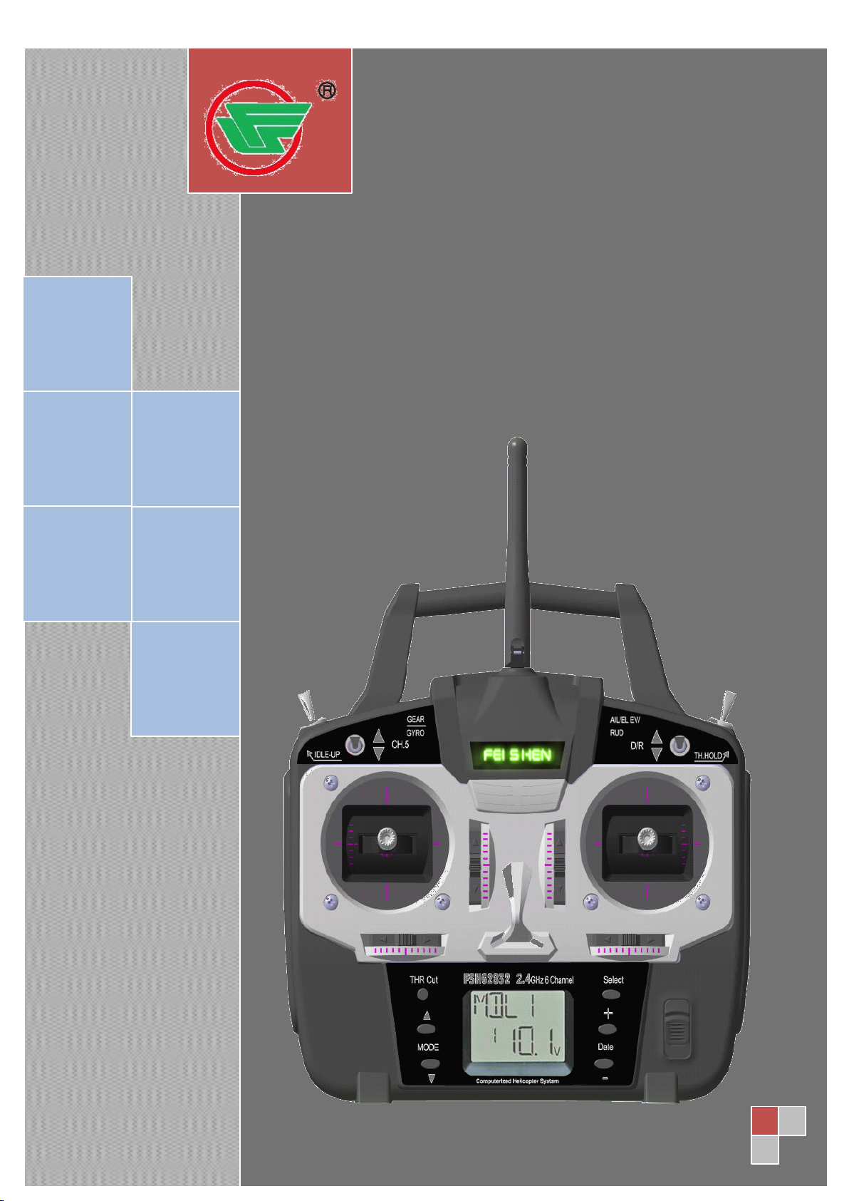
The diagram and explanations briefly describe the functions of the FSH62832 transmitter.
Full instructions on how to operate the controls are provided beginning on page 9.
NOTE
NOTE
NOTE
NOTE : The diagram shows a Mode 2 system as supplied.
controls
controls
controls
TO
THE
TO
THE
TO THE
THE FSH62832
FSH62832
FSH62832
FSH62832 SYSTEM
SYSTEM
SYSTEM
SYSTEM
E.P.A
on all
ESCRIPTIONS:
ESCRIPTIONS:
ESCRIPTIONS:
ESCRIPTIONS:
Aileron,
Aileron,
Aileron,
Aileron, Elevator
Elevator
Elevator
Elevator and
and
Rudder
and
Rudder
and Rudder
Rudder dual
dual
dual
dual rate
rate
switch
rate
switch
rate switch
switch -Use this switch to “ flip ” between two
5
26
5
26
5
5 / 26
26
Page 6

Zhejiang
Zhejiang
Zhejiang
Zhejiang Feishen
aileron, elevator and rudder control throw settings. The throws can be set up however you
prefer, but generally, when the switch is “ up ” the throws are greater ( “ high rate ” ) and when
the switch is “ down ” the throws are less ( “ low rate ” ). This switch also flips between
exponential rates (if used).
Throttle
Throttle
Throttle
Throttle –
disengage it from the Throttle Stick. It is commonly use to practice auto-rotation.
Neck
Neck
Neck
Neck strap
Aileron/elevator
Aileron/elevator
Aileron/elevator
Aileron/elevator control
and channel 2 (elevator) in the receiver
Trim
Trim
Trim
Trim levers
diagram
–
hold
–
hold
– hold
hold switch
strap
hook
strap
hook
strap hook
hook - Mounting point for optional neck strap.
levers
levers
levers ( All
switch
switch
switch - This switch operates to hold the engine in the idling position and
control
control
control stick
All
All
All ) Used to shift the neutral or center position of each servo as labeled in the
stick
stick
stick - Operates the servos connected to channel 1 (aileron)
Feishen
Feishen
Feishen Vehicle
Vehicle
Vehicle
Vehicle CO.,
CO.,
CO.,
CO., LTD
LTD
LTD
LTD .
.
.
.
Charging
Charging
Charging
Charging jack
charger.
On/off
On/off
On/off
On/off switch
DATE
DATE
DATE
DATE “
screen
Liquid
Liquid
Liquid
Liquid -
entered.
Mode
Mode
Mode
Mode " ▲ " and"▼"button-Displayingthemenurollingclockwiseoranti-clockwise.
Select
Select
Select
Select key
Throttle
Throttle
Throttle
Throttle -
Elevator/rudder
Elevator/rudder
Elevator/rudder
Elevator/rudder control
channel 4 (rudder) in the receiver.
Idle-
Idle-
Idle-
Idle- up
curve and pitch curve of mid air maneuvers (rolls, loops, stall turns) and 3D flight.
Gyro
Gyro
Gyro
Gyro switch/
receiver to operate the gyro which has two different senses. Also if you use the 510 Gyro,
two different gyro sense settings on the gyro function in this transmitter can be called by
jack
jack
jack - Port for charging the transmitter batteries with the included battery
switch
switch
switch
“
+
”
“
+
”
“ +
+ ”
” or "-"UsedtochangethevaluesofthevariousfunctionsdisplayedontheLCD
-
crystal
-
crystal
- crystal
crystal display
key
key
key -
-
-
- cut
up
switch--
up
switch--
up switch--
switch-- This switch operates to change the fight condition which sets the throttle
switch/
switch/
switch/ Channel
display
display
display screen
-
-
- Used to display the values for the current function
cut
button
cut
button
cut button
button Be used to shut the throttle completely and immediately.
control
control
control stick-
Channel
Channel
Channel 5--
screen
screen
screen (LCD)
stick-
stick-
stick- Operates the servos connected to channel 3 (throttle) and
5--
5--
5-- You can connect the sense adjust connector to channel 5 of the
(LCD)
(LCD)
(LCD) - Displays programming modes and values
this switch.
Antenna--
Antenna--
Antenna--
Antenna-- Radiates signals to the receiver.
IMPORTANT
IMPORTANT
IMPORTANT
IMPORTANT : Since the 2.4GHz have different characteristics than that of the
conventional 27MHz and 72MHz frequencies, please read this section carefully to enjoy
safe flight with the 2.4GHz system.
Any Changes or modifications not expressly approved by the party responsible
could void the user's authority to operate the equipment
Thisdevicecomplieswithpart15oftheFCCRules.Operationissubjecttothefol
lowingtwoconditions:
(1)Thisdevicemaynotcauseharmfulinterference,
(2)Thisdevicemustacceptanyinterferencereceived,includinginterferencethatmaycauseund
esiredoperation.
6
26
6
26
6
6 / 26
26
for compliance
Page 7
Zhejiang
Zhejiang
Zhejiang
Zhejiang Feishen
Feishen
Feishen
Feishen Vehicle
Vehicle
Vehicle
Vehicle CO.,
CO.,
CO.,
CO., LTD
LTD
LTD
LTD .
.
.
.
Transmitter
Transmitter
Transmitter
Transmitter Antenna
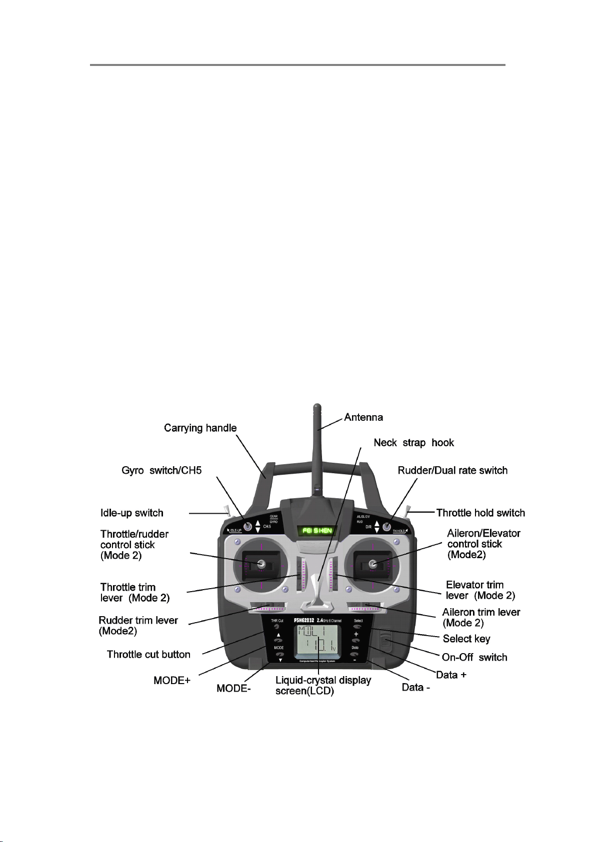
1. The transmitter antenna is adjustable so please make
sure that the antenna is never
pointed directly at the model when flying as this creates a
weak signal for the receiver.
2. Keep the antenna perpendicular to the transmitter's
face to create a better RF condition
for the receiver. Of course this depends on how you hold
the transmitter, but in most cases, adjusting the
transmitter antenna so that it is perpendicular to the face
will give the best results. Please adjust the transmitter antenna to the way you hold the
transmitter.
NEVER
NEVER
NEVER
NEVER grip the antenna when flying as this degrades RF quality.
Features
Features
Features
Features of
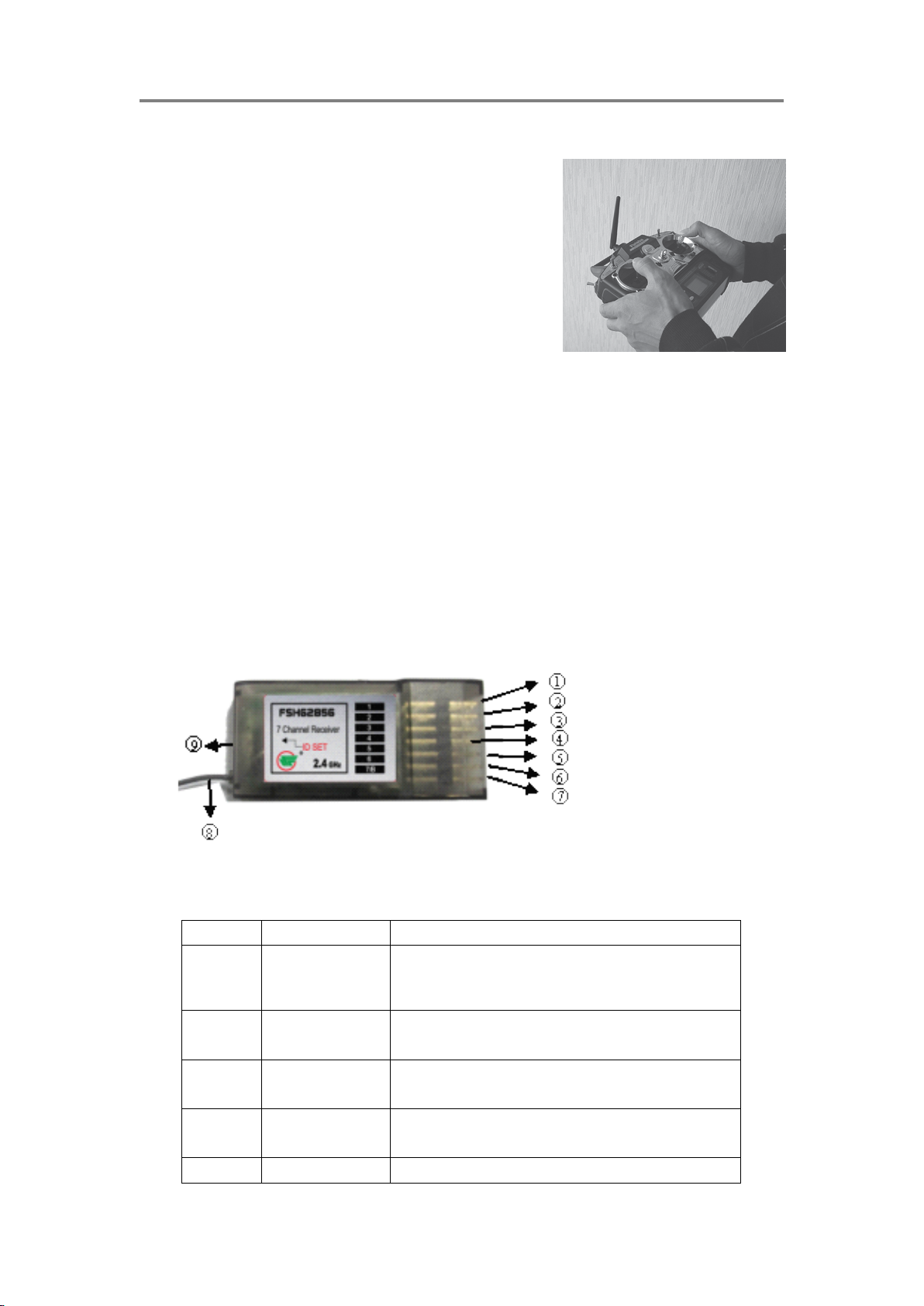
1) FSH62856 receiver, applying 2.4G FHSS tech, has function of matching code
and indicate situation of receiving signals
2) The signal output of 7 channels enables smooth action decomposition and
Antenna
Antenna
Antenna
of
receiver
of
receiver
of receiver
receiver
powerful , practical function .
Main
functions
Main
functions
Main
Main functions
functions of
Number Name Function
1
2
3
4
5
of
receivers
of
receivers
of receivers
receivers
Aileron connecting to the Aileron servo and receiving the
Elevator
Throttle
Rudder
Gyro sensitivity
control signal of Aileron servo
connecting to the elevator servo and receiving the
control signal of elevator.
connecting to the ESC and receiving the signal of
throttle.
connecting to the tail servo and receiving the control
signals from tail servo
connecting to the gyro and receiving control signal of
7
26
7
26
7
7 / 26
26
Page 8
Zhejiang
Zhejiang
Zhejiang
Zhejiang Feishen
6
7 Assistance(batteryAssistant channel or connecting to 4.8V battery
8 antenna receiving remote control signal
9
Link
Procedure
Link
Procedure
Link
Link Procedure
Procedure
Each transmitter has an individually assigned, unique ID code. In order to start operation,
the receiver must be linked with the ID code of the transmitter with which it is being paired.
Once the link is made, the ID code is stored in the receiver and no further linking is
necessary unless the receiver is to be used with another transmitter. (For T/R set, the link
is already done at factory. When you purchased another FSH62856, this procedure is
necessary; otherwise the receiver will not work.
Pitch
"ID SET"
switch
Feishen
Feishen
Feishen Vehicle
sensitivity
connecting to the pitch servo and receiving the control
signal of pitch servo.
Pressing the key for 3 sec and entering into code
learning access.
Vehicle
Vehicle
Vehicle CO.,
CO.,
CO.,
CO., LTD
LTD
LTD
LTD .
.
.
.
1. Place the transmitter and the receiver close to each other within one (1)
meter
2. Turn on the transmitter. and check the transmitter LED on the surface. R adio
is outputting singals when LED always lighted
3. Turn on the receiver.
"ID
SET"
"ID
4. Press down the "ID
(the light will flicker and release the switch. The receiver starts the linking
SET"
"ID SET"
SET" switch on the side of radio f for more than 3 sec
operation
5, When the linking is complete , the LED in the receiver will change to solid green Please
confirm that the servos will now operate by your transmitter
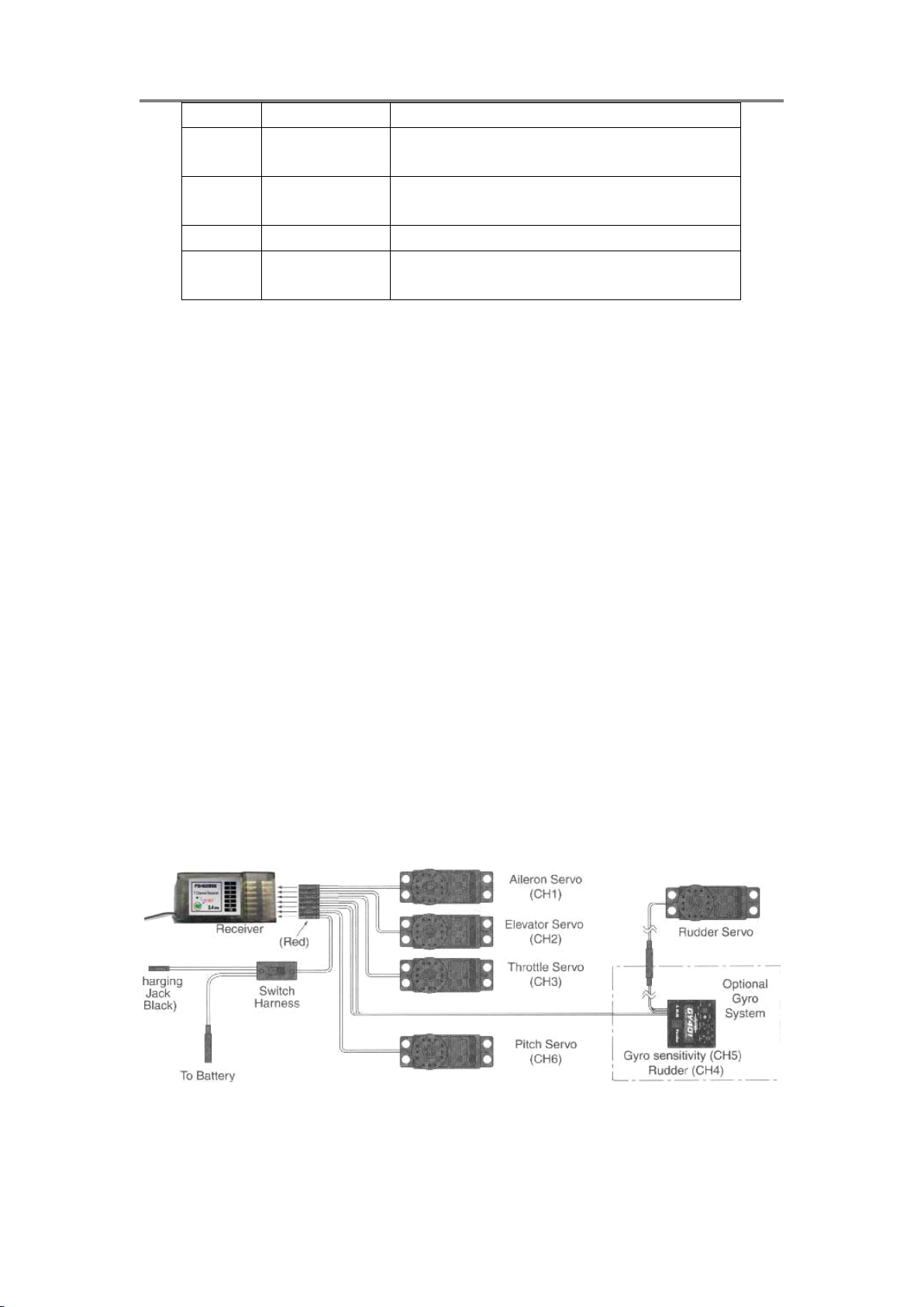
The
picture
The
picture
The
The picture
picture below
below
below
below shows
shows
shows
shows the
the
connection
the
connection
the connection
connection of
should
should
should
should be
be
purchased
be
purchased
be purchased
purchased separately.
of
helicopter
of
helicopter
of helicopter
helicopter model.
separately.
separately.
separately.
model.
model.
model. The
The
gyro
The
gyro
The gyro
gyro and
and
and
Servo
Servo
and
Servo
Servo
8
26
8
26
8
8 / 26
26
Page 9

Zhejiang
Zhejiang
Zhejiang
Zhejiang Feishen
Feishen
Feishen
Feishen Vehicle
Vehicle
Vehicle
Vehicle CO.,
CO.,
CO.,
CO., LTD
LTD
LTD
LTD .
.
.
.
F
unction
F
unction
F
F unction
unction menu
F
unction
F
unction
F
F unction
unction menu
LIQUID
LIQUID
LIQUID
LIQUID CHIP
TO open the
T
hrottle
T
hrottle
T
T hrottle
hrottle off
menu
left
menu
left
menu left
left
menu
right
menu
right
menu right
right
LCD
display
LCD
display
LCD
LCD display
display screen
When the transmitter is initially
modulation
modulation
modulation
modulation type
CHIP
CHIP
CHIP DISPLAY
programming
programming
programming
programming menu
off
off
off key
screen
screen
screen
type
type
type and transmitter
DISPLAY
DISPLAY
DISPLAY (LCD)
menu
menu
menu
key
to
key
key : to
shut
to
shut
to shut
shut off
initially
initially
initially turned on, the model
transmitter
transmitter
transmitter battery
: press MODE" ▲ "and" ▼ "key for one sec.
(LCD)
(LCD)
(LCD) &
off
the
off
the
off the
the
battery
battery
battery voltage
&
PROGRAMMING
&
PROGRAMMING
& PROGRAMMING
PROGRAMMING CONTROLS
SELECT
SELECT
SELECT
SELECT key : to choose the function you
model
model
model type,
voltage
voltage
voltage are displayed on the LCD screen.
type,
type,
type, model
CONTROLS
CONTROLS
CONTROLS
model
model
model memory
memory
memory
memory name
When prompted by the user, the functions and settings stored in the memory can also be
read on the screen. The user accesses the different functions using the MODE key and
SELECT key to visit various functions and DATE ” + ”” - “ key to change number and set.(also
called program)
name
name
name ,
D ata +
D ata -
Notes
Notes
Notes
Notes :
Feel free to explore by scrolling through the
programs and viewing the displays using the
MODE and SELECT keys.The MODE and
SELECT keys only determine what will be
displayed on the screen and will not change any of
the settings. Only when using the
DATA
INPUT
lever will you be able to change any of the settings.
Model
Model
Model
Model name
name
name
name
The FeiShen FSH62832 stores model memories for six models.This means all
the data (control throws, trims, end points,etc.) for up to six different models
can be stored in the transmitter and activated at any time depending upon
which model you choose to fly that day). This eliminates the requirement for
9
26
9
26
9
9 / 26
26
Page 10

Zhejiang
Zhejiang
Zhejiang
Zhejiang Feishen
Feishen
Feishen
Feishen Vehicle
Vehicle
Vehicle
Vehicle CO.,
CO.,
CO.,
CO., LTD
LTD
LTD
LTD .
.
.
.
reconfiguring the transmitter each time you decide to fly a different model with
model
it! When the transmitter is turned on the model
modulation
modulation
modulation
modulation and the transmitter
Before every flight BE
transmitter
transmitter
transmitter voltage
BE
CERTAIN
BE
CERTAIN
BE CERTAIN
CERTAIN that the correct model name for the model
voltage
voltage
voltage will be indicated on the LCD screen.
model
model type,
type,
type,
type, model
model
model
model name,
name,
name,
name,
you intend to fly appears on the screen. If the transmitter is not operating the
correct model, some (or all) of the controls could be reversed and the travels
and trims will be wrong
Flying a model with the wrong program will result in a crash, so always be certain the
model name in the transmitter is correct. One way to ensure this is to write the
corresponding model name directly on the airplane or helicopter, or attach a list to the
bottom or back of the transmitter.
Transmitter
Transmitter
Transmitter
Transmitter battery
In addition to the model type, the LCD screen also
displays the transmitter
voltage goes below approximately 8.5
“ battery ” icon will
continuously beep until the transmitter is turned off.
When the low-battery alarm sounds, land immediately
your model before losing control.
battery
battery
battery voltage
transmitter
transmitter
transmitter battery
voltage
voltage
voltage
battery
battery
battery voltage.
flash
flash
flash
flash
and the low battery alarm will
voltage.
voltage.
voltage. When the
8.5
Volts
8.5
Volts
8.5 Volts
Volts the
immediately
immediately
immediately
Note
Note
Note
Note : If the transmitter ever reaches 8.9 Volts, land as soon as safely possible.
reasonable margin of safety would be to quit flying for the day (or recharge the batteries)
when the transmitter battery reaches 9.4 Volts.
SUGGESTED
SUGGESTED
SUGGESTED
SUGGESTED GUIDELINES:
9.4 Volts - No more flying until recharge.
8.9 Volts - Land as soon as safely possible.
8.5 Volts - Emergency-
Mixer
Mixer
Mixer
Mixer alert
I If the transmitter is turned on with the throttle hold or idle up
function switched on, the screen will show "MIX" and a
warning will sound. Please turn the throttle hold and idle up
functions off to precede.
alert
alert
alert warning
GUIDELINES:
GUIDELINES:
GUIDELINES:
Emergency-
Emergency-
Emergency- Land
warning
warning
warning
Land
Land
Land immediately
immediately
immediately
immediately .
A
more
10
26
10
26
10
10 / 26
26
Page 11

Zhejiang
Zhejiang
Zhejiang
Zhejiang Feishen
Feishen
Feishen
Feishen Vehicle
Vehicle
Vehicle
Vehicle CO.,
CO.,
CO.,
CO., LTD
LTD
LTD
LTD .
.
.
.
PROGRAMMING
PROGRAMMING
PROGRAMMING
PROGRAMMING THE
view
Anytime you wish to view
programming mode must first be entered
MODE
pressing the MODE
second. Once in the program , you can see every function on the rolling menu with
MODE" ▲ " and " ▼ " after entering the program , SELECT key could be used to show
changeable function set. DATE
figure.
You
can return to the home screen (where the model name and battery voltage is
displayed) by pressing the MODE
down for one second.
Note
Note
Note
Note : The functions are listed and described in the order that they appear in the
transmitter. Read all the way through the programming instructions before setting up your
model (if you won ’ t be using any of the mixing functions for a while you
MODE
MODE " ▲ " and " ▼ " keys simultaneously and holding them down for one
view
view or change
change
change
change any of the current settings in the transmitter, the
DATE
DATE
DATE “
“
+
”
“
+
”
“ +
+ ”
” or
MODE
MODE
MODE " ▲ " and " ▼ " keys simultaneously and holding them
THE
THE
THE FSH62832
or
“
-
”
or
“
-
”
or “
“ -
- ”
” key could be used to add or decrease change
FSH62832
FSH62832
FSH62832 RADIO
by,
of course, turning on the power, then by
RADIO
RADIO
RADIO
can read those instructions when ready).
Model
Model
Model
Model choose/data
Model
Model
Model
Model choose
choose/data
choose/data
choose/data reset/Model
choose
choose
choose function
reset/Model
reset/Model
reset/Model type
function
function
function
type
option/Model
type
option/Model
type option/Model
option/Model name
name
name
name
MODL
MODL
MODL
MODL choose
1 、 After entering into program mode (press MODE
" ▼ " keys for 1 sec), The number for the current, active model
will be blinking.
2 、 Pressing DATE
number you need appears.
3 、 Now the model has been selected. All programming inputs from this point forward will
affect only the model number on the screen (until another model number is selected
REST
REST
REST
REST Data
All the data for any model memory can be reset to the original factory defaults. Often this
function is done to get a “ fresh start ” and clear the memory before inputting new model
settings.
Reset data:
1 、 Enter into the program mode (pressing MODE
2 、 Press DATE “ + ” , ” - “ keys till the model serial number
choose
choose
choose model
Data
reset
Data
reset
Data reset
reset function
and
"
▼
and
and
and "
"
"
▼
"
" ▼
▼ "
" key S at same time for 1 seconds.
model
model
model serial
DATE
DATE
DATE ”
function
function
function
serial
serial
serial number
”
+
”
+
” +
+ ”
”
”
” ,
number
number
number
,
“
-
“
,
“
-
“
, “
“ -
- “
“ key till the model serial
MODE
MODE
MODE " ▲ " and
MODE
MODE
MODE "
"
▲
"
▲
" ▲
▲ "
"
"
"
appears
3 、 Once the desired model number is displayed on
the screen, press the SELECT key. “
REST
“
REST
“ REST
REST ”
”
”
” will
“
appear on the screen.
DATE
Press DATE
4 、
“ CLR ” blinks first, and then it stops blinking with a sound. Now the model data is reset
DATE
DATE “
“
+
”
or
”
-
or
or ”
“
”
-
“
” -
- “
“ ke y for about 2 seconds to clear and reset the memory.
11
26
11
26
11
11 / 26
26
“
+
”
“ +
+ ”
” or
Page 12

Zhejiang
Zhejiang
Zhejiang
Zhejiang Feishen
to the initial setting that is the default value set at the factory.
The existing modulation and swashplate type settings are not reset. If the power switch is
turned off while reset is underway, the data may not be reset.
Warning:
Warning:
Warning:
Warning: Resetting current model storage will delete all information of this model forever
and it ’ s beyond recovery (unless you keep the record in the model data record sheet on
the back of notebook). Do not use reset function optionally unless you want to Start it
again.
Feishen
Feishen
Feishen Vehicle
Vehicle
Vehicle
Vehicle CO.,
CO.,
CO.,
CO., LTD
LTD
LTD
LTD .
.
.
.
Setting
Setting
Setting
Setting the
To set a name for model sample, you can pick the model sample you need if you need
through naming a name which easy to remember and identify for every model sample.
1 、 Entering program setting mode. Using DATE
number which you want to change
2 、 Pressing “
sample
3 、 By applying DATE
key to move to next character, you can modify with the same method. Go on modifying
The third and fourth character, you can name your model with four characters.
REVR
REVR
REVR
REVR servo
Servo reversed function is used to react to the radio control input(control stick or switch)
and change the direction of servo action. After setting reverse, please check all of control
on model to ensure all it can move in the right direction. Servo
reverse mistake is the most common reason causing the crash accident.
After applying REVR function, please check operated function of servo structure on your
the
name
the
name
the name
name and
“
SELECT
“
SELECT
“ SELECT
SELECT ”
DATE
DATE
DATE “
servo
servo
servo reversed
reversed
reversed
reversed
and
function
and
function
and function
function of
”
”
” key 3 times, the screen will show the name of current model
“
+
”
“
+
”
“ +
+ ”
” or
of
model
of
model
of model
model
DATE
“
+
”
or
“
-
DATE
“
DATE “
or
“
-
”
or
“
-
”
or “
“ -
- ”
” key to modify the first character and pressing “ SELECT ”
+
“ +
+ ”
”
”
or
“
-
”
” or
or “
“ -
- ”
” key to choose the model serial
model. Unless you reverse the servo on purpose, the reverse mistaken servo and not
check the reaction of control before flying will cause the injury and heli crash.
How
to
set
the
How
to
How
How to
1 、 Enter the programming mode , press MODE"
key
key
key
key to access REVR programming mold
2 、 Press the SELECT key to select the channel you wish
set
to set
set the
servo
the
servo
the servo
servo reverse
reverse
reverse
reverse
MODE"
MODE"
MODE" ▲
▲
"
or
"
▼
or
or "
"
"
▼
"
" ▼
▼ "
"
▲
"
▲ "
" or
to reverse.
DATA
3 、 P ress the DATA
servo, press DATA
DATA
DATA “
DATA
DATA
DATA “
“
-
“
“
-
“
“ -
- “
“ key to reverse (REV) the
“
+
”
“
+
”
“ +
+ ”
” key to make the servo
operate in a normal (NOR) direction.
“
4 、 Press the “
SELECT
“
SELECT
“ SELECT
SELECT ”
”
”
” key to select other channel you wish to reverse
12
26
12
26
12
12 / 26
26
Page 13

Zhejiang
Zhejiang
Zhejiang
Zhejiang Feishen
Dual
Rates/Exponential
Dual
Rates/Exponential
Dual
Dual Rates/Exponential
Rates/Exponential Settings
The aileron, elevator and rudder dual rates on the FSH62832 are simultaneously activated
by the dual rate switch. The amount of travel decrease for each control may be set
between 0% and 100% of the values set for the end points (explained in End Point
Adjustment on page 1 4 ).
Note
Note
Note
Note : It is possible to set a dual rate value to zero, thus causing no response from that
channel. If the dual rates are inadvertently set to zero, a crash could result.
Note
Note
Note
Note : When performing initial model setup, the E.P .A.s should be set prior
dual rates. When setting the E.P.A.s for the first time on a new model, the dual rates
should be set to 100%. .
D/R
Dual
Rate
D/R
Dual
D/R
D/R Dual
Dual Rate
To
select
To
select
To
To select
select the
Settings
Rate
Settings
Rate Settings
Settings
the
Switch/position
the
Switch/position
the Switch/position
Switch/position to
Settings
Settings
Settings
Feishen
Feishen
Feishen Vehicle
to
control
to
control
to control
control the
Vehicle
Vehicle
Vehicle CO.,
the
the
the dual
CO.,
CO.,
CO., LTD
dual
rates:
dual
rates:
dual rates:
rates:
LTD
LTD
LTD .
.
.
.
prior
to
prior
to
prior to
to setting the
MODE"
1 、 Enter the programming mode, press MODE"
to access D/R programming mold
“
SELECT
“
2 、 Press the “
(1-aileron, 2-elevator, 4- rudder). The channel number appears
on the left side of the screen
Note : if an “
and access “
3 、 Place the dual rate switch (selected previously) in the desired position for the value you
wish to change . (generally, pilots prefer to have the switch in the “ up ” position for the high
rate, and in the “
4 、 Change the dual rate value for the respective channel using the DATA
until the desired control throw is achieved. If you wish to change the control throw when
the switch is in the other position as well, move the switch accordingly, then use the DATA
“
+
”
or
“
-
“
+
”
“
“ +
+ ”
” or
5 、 Repeat procedure 3 and procedure 4 to set the dual rates for other channels.
“
or
“
-
“
or “
“ -
- “
“ lever to change the throw rates.
“ SELECT
“
EXPO
“
EXPO
“ EXPO
EXPO ”
“
EXPO
“
EXPO
“ EXPO
EXPO “
SELECT
SELECT ”
“
down
“
down
“ down
down ”
”
”
” key to choose the desired channel
”
”
” is shown on the screen, that means you press “
“
“
“ set mode. Press “
”
”
” position for the low rate.
MODE"
MODE" ▲
“
SELECT
“
SELECT
“ SELECT
SELECT ”
▲
"
or
"
▼
▲
"
▲ "
" or
”
”
” to get back to dual rate setting.
"
or
"
▼
"
or "
" ▼
▼ "
" key
“
SELECT
“
SELECT
“ SELECT
SELECT ”
DATA
DATA
DATA “
“
+
“
“
+
“
“ +
+ “
“ or
”
”
” too long,
or
“
-
”
or
“
-
”
or “
“ -
- ”
” lever
DATA
DATA
DATA
(channel 2-elevator, channel 4-rudder)
Exponential
Exponential
Exponential
Exponential Settings
Settings
Settings
Settings
“
EXPO
“
Exponential, or “
affects the travel of the servos around their center in
relationship to stick movement. Exponential does NOT
impact the overall travel volume of the servos. A negative
“ - “ exponential input will soften or reduce the servo ’ s
movements near the control ’ s neutral position. A positive “ + ”
exponential input will increase the servo ’ s movements near the control ’ s neutral position.
Exponential set could between -100% and +100%.
EXPO
“ EXPO
EXPO “
“
“
“ as it is commonly abbreviated,
13
26
13
26
13
13 / 26
26
Page 14

Zhejiang
Zhejiang
Zhejiang
Zhejiang Feishen
To
set
the
To
set
To
To set
set the
1 、 Enter the programming mode, press MODE "
2 、 Press DELECT to choose “
3 、 Press the “
4-rudder), the channel number appears on the left side of the screen. Note if the D/R was
shown on the screen, it because you have pressed SELECT many times and access to
D/R setting screen, press “
4 、 Place the dual rate switch in the desired position for the value you wish to change
exponentials:
the
exponentials:
the exponentials:
exponentials:
“
SELECT
“
SELECT
“ SELECT
SELECT ”
”
”
” key to choose the desired channel (1-aileron, 2-elevator,
“
SELECT
“
SELECT
“ SELECT
SELECT “
Feishen
Feishen
Feishen Vehicle
“
EXPO
“
EXPO
“ EXPO
EXPO ”
“
“
“ key to get back to the setting screen.
”
”
” function
Vehicle
Vehicle
Vehicle CO.,
"
"
" ▲
CO.,
CO.,
CO., LTD
▲
"
or
▲
"
or
▲ "
" or
or "
LTD
LTD
LTD .
"
▼
"
"
▼
"
" ▼
▼ "
" key to choose "D/R"
.
.
.
"D/R"
"D/R"
"D/R" function
DATE
5 、 Change the exponential rate value for the respective channel using the DATE
“
-
”
“
-
”
“
“ -
- ”
” until the desired exponential value is achieved, as stated above, an exponential value
“
-
”
“
-
with a “
6 、 Place the dual rate/exponential switch in the opposite position, adjust the rates
accordingly.
7 、 Repeat the procedure for the remaining channels as desired.
EPA
EPA
EPA
EPA End
Note
Note
Note
Note : since changing the end points will also change the dual rates, the end points should
be set prior to setting the dual rates. If you set the dual rates first, and the go back and
change the end points, the dual rate throws will also change.
Adjusting each servo throw, and each servo ’ s left & right
throw could be adjusted separately.( When EPA setting
in 100%, the maximum servo throw for channels 1,2,3
and 4 is approximately 40 degree, and approximately
”
“ -
- ”
” in front of it makes the initial servo movement less, or “ softer ” .
End
Point
End
Point
End Point
Point Adjustment
Adjustment
Adjustment
Adjustment setting
setting
setting
setting
DATE
DATE “
“
+
”
“
+
”
“ +
+ ”
” or
or
or
or
55 degree for channels 5 and 6.
To
set
the
end
To
set
To
To set
1 、 Enter the programming mode, press either MODE
function menus, activate channel No. will shown on the left side of screen, the sign of “ % ”
will flicker.
2 、 Moving the aileron stick to right and press DATE
“
“
“
“ -
3 、 Moving the aileron stick to left and press DATE
“
“
“
“ -
4 、 Press “
adjusted. Note: moving the stick (or switch) from one end
to the other changes the value displayed and the position of the arrow for that “ end ” of the
control input.
TRIM
TRIM
TRIM
TRIM Trim
the
set the
the end
-
”
-
”
- ”
” key to change the value as desired.
-
”
-
”
- ”
” key to change the value as desired.
Trim
Trim
Trim settings
end
end points
“
SELECT
“
SELECT
“ SELECT
SELECT ”
settings
settings
settings
points
points
points :
:
:
:
MODE
MODE
MODE " ▲ " or " ▼ " to scroll through "EPA"
DATE
DATE
DATE “
DATE
DATE
DATE “
”
”
” key to display the next channel to be
14
14
14
14 / 26
“
+
“
+
“ +
+ ”
“
+
“
+
“ +
+ ”
26
26
26
”
”
” or
”
”
” or
"EPA"
"EPA"
"EPA"
or
or
or
or
or
or
Page 15

Zhejiang
Zhejiang
Zhejiang
Zhejiang Feishen
There are four trim levers ( “ trims ” ) on the front of the transmitter. Three of the trims are for
adjusting the neutral position of the aileron, elevator and rudder servos. The fourth trim is
for setting the idle r.p.m. of the engine when the throttle stick is all the way down. The
intended use of the trims is to make small servo adjustments, in flight, to get the model
properly “ trimmed ” (so it will fly straight-and-level). Because the trims are intended to be
used while the model is in flight, you do not have to “ enter the program ” to adjust the trims.
Simply push or pull on the trim levers while flying and the neutral position of the servos will
shift. Keep in mind that you should start out with the control surfaces centered when the
servos are centered and the trims are “ zeroed ” (or near zero).
trims once airborne.
Center
Center
Center
Center the
1 、 Turn on the transmitter and receiver. Operate the controls to make sure the servos
respond in the correct direction. Use the reversing function to reverse any servos
necessary.
2 、 Center the throttle control stick.
3 、 Place the servo arms on the servos so they are perpendicular to the pushrods . It is
okay to cut off any unused
servo arms.
4 、 Connect the pushrods to the control surfaces. Adjust the length of the pushrods until the
control surfaces are centered when the servos are centered
the
servos:
the
servos:
the servos:
servos:
Feishen
Feishen
Feishen Vehicle
Vehicle
Vehicle
Vehicle CO.,
CO.,
CO.,
CO., LTD
LTD
LTD
LTD .
.
.
.
THEN
THEN
THEN
THEN
you can adjust the
Note
Note
Note
Note : The throttle trim affects the throttle servo only when the throttle stick is below “ 1/2
stick. ” This way, the final closing of the carburetor can be adjusted without affecting the
servo throughout the rest of the range.
To
adjust
To
adjust
To
To adjust
adjust the
Once the servos and control surfaces have been connected and the control throws have
been set using the end points and dual rates, get the model airborne. Adjust the trims as
necessary to get the model to fly straight-and-level. If much trim is
required on any one control it is a good idea to readjust the pushrods so the trims can be
returned to neutral (zero). Adjusting the trims with the trim levers changes the servo’s
position in increments of “ 4. ” If finer adjustments are required, land the model, then enter
the program as described below to adjust the trims in increments of “ 1. ”
1 、 Enter program setting, press MODE
2 、 Press “
(the figure shows adjustments for CH1)
3 、 Adjust the trim using the DATE
values change in increments of “ 1 ” at initial, but if the DATA
“
+
”
“
+
”
“
“ +
+ ”
” or
or
or
or “
the
trim
the
the trim
“
SELECT
“
SELECT
“ SELECT
SELECT ”
“
-
”
i
“
-
”
i
“ -
- ”
” i
i s held long enough the values will change more
settings:
trim
settings:
trim settings:
settings:
MODE
MODE
MODE "
”
”
” key to display the channel to be adjusted
DATE
DATE
DATE “
"
▲
"
or
"
▲
"
or
" ▲
▲ "
" or
or "
“
+
”
or
“
-
“
+
”
“ +
+ ”
” or
”
or
“
-
”
or “
“ -
- ”
” key , note that
"
▼
"
"
▼
"
" ▼
▼ "
" to get into “ TRIM
DATA
DATA
DATA
TRIM
TRIM
TRIM “
“
“
“ menu .
.
.
.
rapidly.
4 、 Adjusting other channels based on above.
N-TH
N-TH
N-TH
N-TH Normal
Normal
Normal
Normal throttle
throttle
throttle
throttle curve
curve
curve
curve function
function
function
function
15
15
15
15 / 26
26
26
26
Page 16

Zhejiang
Zhejiang
Zhejiang
Zhejiang Feishen
Used to set throttle curve for normal flight. 5-point throttle curve is utilized to best match
the blade collective pitch to the engine RPM for consistent load on the engine. Throttle
curve can be adjusted from 0-100% each point. This normal throttle curve creates a basic
curve for hovering. Use this function together with the normal pitch curve (see Normal
pitch curve) so that up/down control has a constant engine speed.
To
set
the
To
set
To
To set
set the
1 、 Enter the programming mode, press MODE
" ▼ "key to access the “
position number will appear on left side of display and “ % ”
symbol will be flashing.
2 、 Press “
Point 1 is shown initially which is throttle stick all the way
downward (slow) position. Point 5 is throttle stick all the
way upward (hi) position.
3 、 Press DATE
normal
the
normal
the normal
normal throttle
“
SELECT
“
SELECT
“ SELECT
SELECT ”
DATE
DATE
DATE “
throttle
throttle
throttle curve:
”
”
” key to select the desire curve point.
“
+
”
or
“
+
”
or
“ +
+ ”
” or
or “
curve:
curve:
curve:
“
N-TH
“
N-TH
“ N-TH
N-TH ”
“
-
”
“
-
”
“ -
- ”
” to set the servo position
Feishen
Feishen
Feishen Vehicle
”
”
” function. , Throttle stick
Vehicle
Vehicle
Vehicle CO.,
MODE
MODE
MODE " ▲ " or
CO.,
CO.,
CO., LTD
LTD
LTD
LTD .
.
.
.
SELECT
4 、 Use “ SELECT
N-PI
N-PI
N-PI
N-PI Normal
Used to set pitch curve for normal flight. 5-point pitch curve is utilized to best match the
blade collective pitch to the engine RPM for consistent load on the engine. Pitch curve can
be adjusted from 0-100% each point.
This normal pitch curve creates a basic curve for hovering. Use this function together with
the normal throttle curve so that up/ down control has a constant engine speed.
To
To
To
To set
1 、 Enter the programming mode, press either the MODE
"
▲
"
▲
"
" ▲
▲ "
position number will appear on left side of the display and
“ % ” symbol will be flashing.
2 、 Press “
SELECT
SELECT ”
Normal
Normal
Normal pitch
set
the
set
the
set the
the normal
"
or
"
▼
"
or
"
▼
" or
or "
" ▼
▼ "
“
“
“ SELECT
normal
normal
normal pitch
SELECT
SELECT
SELECT ”
”
”
” key to set other points in same manner
pitch
curve
pitch
curve
pitch curve
curve function
pitch
pitch
pitch curve:
"
"
" to access the “
function
function
function
curve:
curve:
curve:
“
N-PI
”
“
N-PI
”
“ N-PI
N-PI ”
” function ,
”
”
” key to select the desired curve point.
MODE
MODE
MODE
,
,
, Throttle stick
Point 1 is shown initially, which is throttle stick all the way
downward (slow) position. Point 5 is throttle stick all the
way upward (hi) position.
DATE
3 、 Press DATE
4 、 Use “
I-TH
I-TH
I-TH
I-TH Idle-up
Used to set throttle curve for idle up flight. 5-point throttle
DATE
DATE “
“
SELECT
“
SELECT
“ SELECT
SELECT ”
Idle-up
Idle-up
Idle-up throttle
“
+
”
or
“
-
”
“
+
”
“ +
+ ”
” or
”
”
” key to set other points with same manner.
throttle
throttle
throttle curve
to
or
“
-
”
to
or “
“ -
- ”
” to
to set the servo position
curve
curve
curve function
function
function
function
16
26
16
26
16
16 / 26
26
Page 17

Zhejiang
Zhejiang
Zhejiang
Zhejiang Feishen
curve is utilized to best match the blade collective pitch to the engine RPM for consistent
load on the engine when idle up function is on. Throttle curve can be adjusted from
0-100% each point. This idle up throttle curve is to set consistent engine RPM and can be
activated at any time when mid air maneuvers are executed, such as loops, rolls, and 3D
flight, even when the blade collective pitch is reduced.
To
set
the
To
To
To set
set
set the
idle-up
the
idle-up
the idle-up
idle-up throttle
throttle
throttle
throttle curve:
curve:
curve:
curve:
Feishen
Feishen
Feishen Vehicle
Vehicle
Vehicle
Vehicle CO.,
CO.,
CO.,
CO., LTD
LTD
LTD
LTD .
.
.
.
MODE"
1 、 Enter the programming mode, press MODE"
function
DATE
2 、 press DATE
display to change to a flashing ON display. The throttle
curve point indication on the left side of screen, and the
sign of “ % ” will flicker.
3 、 P ush “ SELECT
1 is shown initially which is throttle stick’s all the way
downward (slow) position. Point 5 is throttle stick’s all the
way upward (hi) position.
DATE
DATE “
SELECT
SELECT
SELECT ”
“
+
”
key
“
“ +
”
”
” key to select the desired curve point. Point
,
+
”
key
,
+ ”
” key
key ,
, this will cause the flashing INH
MODE"
MODE" ▲
▲
"
▲
"
▲ "
" or
or
"
▼
"
or
"
▼
"
or "
" ▼
▼ "
" key to access the “
“
“
“ I-TH
I-TH
I-TH
I-TH ”
”
”
”
DATE
4 、 press DATE
5 、 Use “
I-PI
I-PI
I-PI
I-PI Idle-up
Used to set pitch curve for idle up flight. 5-point pitch curve is utilized to best match the
blade collective pitch to the consistent engine RPM when idle up is used. Pitch curve can
be adjust from 0-100% each point.
The high side pitch curve should be set to not overload the engine and keep consistent
engine RPM. Generally, set less pitch than normal maximum pitch. The low side pitch
curve should be set for desired maneuvers such as loops, rolls, and 3D flight
To
To
To
To set
1. Enter the programming , press MODE"
2. Press DATE:
DATE
DATE “
“
SELECT
“
SELECT
“ SELECT
SELECT ”
Idle-up
Idle-up
Idle-up pitch
set
the
set
the
set the
the idle-up
access the “
into flash “ on ” so that I-TH function has been turned on. And then, the number in each
“
+
”
“
+
”
“ +
+ ”
” or
”
”
” key to set other points in same manner
pitch
pitch
pitch curve
idle-up
idle-up
idle-up pitch
“
I-PI
“
I-PI
“ I-PI
I-PI ”
DATE:
DATE:
DATE: “
“
+
“
+
“ +
+ ”
or
“
-
”
or
“
-
”
or “
“ -
- ”
” key to set the servo position. .
curve
curve
curve function:
pitch
curve:
pitch
curve:
pitch curve:
curve:
”
”
” function
”
”
” key , the flash “ INH ” will be changed
function:
function:
function:
MODE"
MODE"
MODE" ▲
▲
"
or
"
▼
or
or "
"
" ▼
▼
▼ "
"
"
" key to
▲
"
▲ "
" or
.
.
.
17
26
17
26
17
17 / 26
26
Page 18

Zhejiang
Zhejiang
Zhejiang
Zhejiang Feishen
curve will be show n on the left of screen, meanwhile, the sign of right “ % ” will flash.
“
I-TH
“
When the function of “
“
I-TH
”
“
I-TH
”
“
“ I-TH
I-TH ”
” should be activated before applying “
“
SELECT
“
3 、 Press “
Point 1 is shown initially which is throttle stick’s all the
way downward (slow) position. Point 5 is throttle stick’s
all the way upward (hi) position.
SELECT
“ SELECT
SELECT ”
”
”
” key to select the desired curve point.
“ I-TH
I-TH
I-TH ”
Feishen
Feishen
Feishen Vehicle
”
”
” being shut ted down, this function couldn ’ t be operated.
Vehicle
Vehicle
Vehicle CO.,
“
I-PI
“
I-PI
“ I-PI
I-PI ”
”
.
”
.
” .
.
CO.,
CO.,
CO., LTD
LTD
LTD
LTD .
.
.
.
DATE
4 、 press DATE
5 、 Use SELECT key to set other points in same manner
HOLD
HOLD
HOLD
HOLD Throttle
Throttle hold function is to be used for autorotations where
only pitch control is used to make a descent and landing.
Just flip the hold switch on to set the engine in the idling or
cut position and disengage it from the Throttle Stick. It can
be set from (-)50 to (+)50% from throttle trim position.
To
To
To
To set
1. Enter the programming , press MODE"
DATE
DATE “
Throttle
Throttle
Throttle hold
set
the
set
the
set the
the throttle
access the “
“
+
”
or
“
+
”
or
“ +
+ ”
” or
or “
hold
hold
hold function
throttle
throttle
throttle hold:
“
HOLD
“
HOLD
“ HOLD
HOLD ”
hold:
hold:
hold:
“
-
”
“
-
”
“ -
- ”
” key to set the servo position. .
function
function
function
”
”
” function
MODE"
MODE"
MODE" ▲
▲
"
or
▲
"
or
▲ "
" or
or "
"
"
" ▼
▼
▼
▼ "
.
.
.
"
"
" key to
2. Press DATE “ + ” button, you could switch into flash “ ON ”
from flash “ INH ” . This way, HOLD functions will be on!
3. Pressing SELECT once, the screen will show
numbers.Using DATE “ + ” or “ - “ button to set up the
throttle servo position when throttle keep.
REVO
REVO
REVO
REVO Screw
This mix adds rudder in conjunction with pitch. This helps
compensate for rotation of the helicopter caused by the increased engine torque. (Never
use revo. mixing with a heading-hold/AVCS gyro which is in heading hold/AVCS mode.
Screw
Screw
Screw pitch-rudder
pitch-rudder
pitch-rudder
pitch-rudder mixing
mixing
mixing
mixing functions:
functions:
functions:
functions:
18
26
18
26
18
18 / 26
26
Page 19

Zhejiang
Zhejiang
Zhejiang
Zhejiang Feishen
However, revo.mixing is still used when a heading-hold/AVCS gyro is in normal mode.)
To
set
the
To
set
To
To set
set the
1. Enter the programming mode and use the MODE
"
"
"
" ▲
REVO
the
REVO
the REVO
REVO mixing:
▲
"or"
▲
"or"
▲ "or"
"or" ▼
mixing:
mixing:
mixing:
▼
"
▼
"
▼ "
" key to access the “
Feishen
Feishen
Feishen Vehicle
“
REVO
“
REVO
“ REVO
REVO ”
Vehicle
Vehicle
Vehicle CO.,
”
”
” function.
CO.,
CO.,
CO., LTD
MODE
MODE
MODE
LTD
LTD
LTD .
.
.
.
DATE
2. Press DATE
Press “
time, It can set mixing amount on throttle stick hi side and low
side separately . When you move the throttle stick to the low
side from neutral , the arrow indicates down direction. , this time,
press DATE
side. When you move the throttle stick to the high side from
neutral, the arrow indicates up direction. the arrow indicates up
direction. Then press DATE
amount of the low side.
GYRO
GYRO
GYRO
GYRO Gyro
GYROS
GYROS
GYROS
GYROS : Using electronics to take some of the
complexity out of setups and flight. What is a
gyro?
senses rotational movement and corrects for it.
For example, if the wind blows your
helicopter’s tail to the left, a gyro will sense that
motion (and confirm that no input was given)
and will correct for it.
How does it help in helicopter setup?
mixing. The gyro will sense and correct the unwanted motion for you, so you don’t have to
spend time to get a complex curve operating properly
DATE
display to change to a flashing “
“
REVO
“
REVO
“
“ REVO
REVO ”
“
SELECT
“
SELECT
“ SELECT
SELECT ”
DATE
DATE
DATE “
Gyro
Gyro
Gyro mixing
A
gyroscope is an electronic unit that
“
+
”
“
+
DATE “
”
”
” function is on.
”
“ +
+ ”
” key, This will cause the flashing “
”
”
” key once This will cause the flashing “ % ” symbol on the display. this
“
+
”
or
“
“
+
“ +
+ ”
-
”
or
“
-
” or
or “
“ -
- “
DATE
DATE
DATE “
mixing
mixing
mixing function
“
INH
“
INH
“ INH
INH ”
“
ON
”
“
ON
”
“ ON
ON ”
” display. Now the
“
“
“ key to set the mixing amount of the low
“
+
”
or
“
-
“
or
“
-
“
or “
“ -
- “
“ key to set the mixing
A
good gyro will totally eliminate the need for revo.
function
function
function
“
+
”
“ +
+ ”
” or
”
”
”
Gyro sensor kinds: There are many different kinds of gyros. Early gyros were mechanical,
with a spinning drum similar to a child’s gyroscope toy. The next generation utilized a
special type of crystal, called piezoelectric, which sensed the motion and provided an
electrical pulse. The finest gyros at the time of this writing are SMM technology. These
silicone micro machines, or computer chips, sense the motion. SMM is far more accurate
and less susceptible to inaccuracies caused by temperature changes, etc.
19
26
19
26
19
19 / 26
26
Page 20

Zhejiang
Zhejiang
Zhejiang
Zhejiang Feishen
Feishen
Feishen
Feishen Vehicle
Vehicle
Vehicle
Vehicle CO.,
CO.,
CO.,
CO., LTD
LTD
LTD
LTD .
.
.
.
Choosing
Choosing
Choosing
Choosing the
•
Mechanical:
•
Mechanical:
•
• Mechanical:
Mechanical: some are still available. They are very challenging to set up and not as
reliable as piezo or SMM.
•
Non-Heading-Hold
•
Non-Heading-Hold
•
• Non-Heading-Hold
Non-Heading-Hold Piezo:
to set up. Some have dual rates and
remote gain control to adjust sensitivity in flight. Lack heading-hold capabilities for
precision flying.
•
Heading-Hold
•
Heading-Hold
•
• Heading-Hold
Heading-Hold Piezo:
complex to set up. Adds GPS-like heading
recognition. Exhibits minor difficulties with temperature drift (position setting varying with
unit’s temperature).
•
Heading-Hold
•
Heading-Hold
•
• Heading-Hold
Heading-Hold SMM:
Expensive, easier set up, higher durability.
Significant decrease in temperature sensitivity. Many include frame rate settings to allow
faster response when using specialized digital servos.
Gyro mixing function is used for adjusting the gain of the gyro. Select from two different
gain settings using a switch on the transmitter.
the
right
the
right
the right
right gyro
gyro
for
your
gyro
for
gyro for
for your
Piezo:
Piezo:
Piezo: these are now inexpensive gyros that are reliable and easy
Piezo:
Piezo:
Piezo: Until recently, the cream of the crop. Expensive, and more
SMM:
SMM:
SMM: 21st Century gyro technology. Computer chip technology.
skills,
your
skills,
your skills,
skills, your
your
helicopter,
your
helicopter,
your helicopter,
helicopter, and
and
your
and
your
and your
your budget:
budget:
budget:
budget:
To
set
the
To
set
To
To set
set the
1. Plug the gyro’s sensitivity adjustment to channel 5 of the receiver. (not assignable)
2. “
3. Enter the programming mode and press the MODE
4. press DATE
GYRO
the
GYRO
the GYRO
GYRO mixing:
“
EPA
“
EPA
“ EPA
EPA “
"
▲
"or"
"
▲
"or"
"
" ▲
▲ "or"
"or" ▼
from flash “ INH ” , this mixedcontrol function will work.
mixing:
mixing:
mixing:
“
“
“ of channel 5 (see page 14-15 ) to set 100% both UP and DOWN. .
MODE
MODE
MODE
▼
"
▼
"
▼ "
" key to access the “
DATE
DATE
DATE "+"
"+"
"+"
"+" key . you could switch into flash “ ON ”
“
GYRO
“
GYRO
“ GYRO
GYRO ”
”
”
” function
SELECT
5. Pressing “ SELECT
gain setting and flashing “ % ” symbol on the display.
SELECT
SELECT ” key once This will show the gyro
20
20
20
20 / 26
26
26
26
Page 21

Zhejiang
Zhejiang
Zhejiang
Zhejiang Feishen
Flip the gyro (CH5) switch up and down. This will cause the arrow on the display to point
up and down corresponding to the switch position. Push up or down
set the gyro gains for both switch up and down position. Gyro gain can
be adjust from -100% to +100%.
Feishen
Feishen
Feishen Vehicle
Vehicle
Vehicle
Vehicle CO.,
CO.,
CO.,
CO., LTD
LTD
LTD
LTD .
.
.
.
DATA
INPUT lever to
You can choose the FEISHEN GY510 specially digital gyroscope, its configuration
simple. Practice stunt flying to 3D flying ideal choice. Product Numbers for FSH62851.
21
26
21
26
21
21 / 26
26
Page 22

Zhejiang
Zhejiang
Zhejiang
Zhejiang Feishen
Feishen
Feishen
Feishen Vehicle
Vehicle
Vehicle
Vehicle CO.,
CO.,
CO.,
CO., LTD
LTD
LTD
LTD .
.
.
.
SWSH
SWSH
SWSH
SWSH Swashplate
choose 3-S type.
1-S
1-S
1-S
1-S : Independent aileron, pitch and elevator servos
linked to the swashplate. Most kits are 1-S type
3-S
3-S
3-S
3-S : With Aileron inputs, the aileron and pitch servos tilt
the swashplate left and right; with Elevator inputs, the
three servos tilt the swashplate fore and aft; with Pitch
inputs, all three servos raise the swashplate up and
down.
To
To
To
To select
1. Enter the programming mode and press the MODE
"
"
"
" ▲
Swashplate
Swashplate
Swashplate types
This function can select from two swashplate types. Swash AFR can be set, if you
select
select
select the
▲
"or"
▲
"or"
▲ "or"
"or" ▼
the
the
the swashplate
▼
"
▼
"
▼ "
" key to access the “
types
types
types selection
swashplate
swashplate
swashplate types:
selection
selection
selection &
types:
types:
types:
“
“
“ SWSH
SWSH
SWSH
SWSH ”
&
Swash
&
Swash
& Swash
Swash AFR
”
”
” function.
AFR
AFR
AFR
MODE
MODE
MODE
DATE
“
+
”
or
“
-
DATE
2 、 Using DATE
swashplate mode. Please press DATE
want to choose “ 1-S ” mode; Please press DATE
you want to choose “ 3-S ” mode
3 、 1-S or 3-S on the screen will flicker and stop flickering with
warning tone when you are chaging swashplate mode.
4 、 Now the swashplate mode has been setted well.
To
set
To
To
To set
Only when you choose 3-S swashplate mode then you can use the function “
AFR
AFR
AFR
AFR ”
and pitch servo.
the
set
the
set the
the swash
”
”
” .The function is used to change the moving direction and stroke of aileron,pitching
“
DATE “
“ +
swash
swash
swash AFR:
+
+ ”
AFR:
AFR:
AFR:
”
”
or
“
-
”
” or
or “
“ -
- ”
” key for about two Seconds to select
DATE
“
+
DATE
DATE “
”
“
+
”
“ +
+ ”
” key when you
DATE
“
DATE
DATE “
-
”
“
-
”
“ -
- ”
” key when
“
SWASH
“
SWASH
“ SWASH
SWASH
At first, please assemble aileron,pitching and pitch servo with model well according to
“
EPA
”
instruction manual.Then to set the three servo ’ s “
set servos “ reverse ” function (see page 1 2 ) to keep swashplate moves up and download
horizontal and correct when operating pitch(up and down throttle lever).
22
22
22
22 / 26
“
“ EPA
26
26
26
value
EPA
”
value
EPA ”
” value
value (see page 14 ) to 100% and
Page 23

Zhejiang
Zhejiang
Zhejiang
Zhejiang Feishen
1 、 .Enter the programming mode and use the MODE "
“
SWSH
“
SWSH
“
“ SWSH
SWSH ”
2 、 Ensure you have choosed 3-S swashplate mode.If not,please set according to
“ Choose swashplate type ” .
3 、 Press “ SELECT
to set. Aileron channel “
flashing.
Move aileron lever left and right, use DATE
the direction and amount of aileron servo. The movement of
aileron servo can be adjusted between -100% and +100%.
”
”
” function.
SELECT
SELECT
SELECT ” key to select the channel that you want
“
CHA
“
CHA
“ CHA
CHA ”
Feishen
Feishen
Feishen Vehicle
”
”
” is displayed at first and “ % ” is
DATE
DATE
DATE “
Vehicle
Vehicle
Vehicle CO.,
“
+
”
or
“
-
”
or
” or
or “
”
“
-
”
“ -
- ”
” key to set
“
+
“ +
+ ”
CO.,
CO.,
CO., LTD
"
"
" ▲
LTD
LTD
LTD .
▲
"or"
▲
"or"
▲ "or"
"or" ▼
.
.
.
▼
"
key
▼
"
key
▼ "
" key
key to access the
“
SELECT
“
4 、 Select other channels (elevator and pitch) by “
to set the direction and amount of servo movement in same
manner as aileron channel setting.
CHE
CHE
“ CHE
CHE ” shows elevator channel, “ CHP
CHP
CHP
CHP ” shows pitch channel.
SELECT
“ SELECT
SELECT ”
”
”
” key
23
26
23
26
23
23 / 26
26
Page 24

Zhejiang
Zhejiang
Zhejiang
Zhejiang Feishen
Feishen
Feishen
Feishen Vehicle
Vehicle
Vehicle
Vehicle CO.,
CO.,
CO.,
CO., LTD
LTD
LTD
LTD .
.
.
.
FLOW
FLOW
FLOW
FLOW CHART
Enter or exit the program mode and keep pressing MODE
If you want to change control lever mode, please keep pressing MODE
key and open transmitter power. Use DATE
CHART
CHART
CHART of
DATE
“
+
”
DATE
DATE “
or
“
+
”
or
“ +
+ ”
” or
or “
of
FSH62832
of
FSH62832
of FSH62832
FSH62832
MODE
MODE
MODE "
“
-
”
“
-
”
“ -
- ”
” key to display the control lever mode.
"
▲
"
"
" and "
"
"
" ▼
MODE
MODE
MODE "
"
▲
" ▲
▲ "
▼
"
▼
"
▼ "
" key for a second.
"
▲
"
"
" and "
"
"
" ▼
"
▲
" ▲
▲ "
▼
"
▼
"
▼ "
"
24
26
24
26
24
24 / 26
26
Page 25

Zhejiang
Zhejiang
Zhejiang
Zhejiang Feishen
Feishen
Feishen
Feishen Vehicle
Vehicle
Vehicle
Vehicle CO.,
CO.,
CO.,
CO., LTD
LTD
LTD
LTD .
.
.
.
Other
Other
Other
Other functions
simulator
simulator
simulator
simulator
Simulator function of FSH62832 is a function for beginners to practise by connecting to
computer
How
to
use
How
to
How
How to
to use
Please connect one end of simulated line to computer and the
other end to simulate output terminal at the back of transmitter.
Now we can set data after we connecting all well and turning
transmitter on.
Throttle-cut
Throttle-cut
Throttle-cut
Throttle-cut function
Throttle closing function is used when engine need to be switched off by human.It can be
rapid and convenient to switched off engine by use “ THR
zero at moment when keep pressing “ THR
throttle value returns to lever equivalent value when loosen “ THR
simulator?
use
simulator?
use simulator?
simulator?
function
function
function
functions
functions
functions of
THR
CUT
THR
CUT
THR CUT
CUT ” no matter where is throttle lever.But
of
FSH62832
of
FSH62832
of FSH62832
FSH62832
THR
CUT
THR
CUT
THR CUT
CUT ” switch.Throttle output to be
THR
CUT
THR
CUT
THR CUT
CUT ” button.
Adjustable-length
Adjustable-length
Adjustable-length
Adjustable-length control
You can adjust control lever length
according individual need. Rotate set
screw A counterclockwise unscrew and
then rotate lever nut B up or down when
you need adjust the lever length.Rotate set
screw A clockwise to tight lever nut B after
adjust the lever length.
Changing
Changing
Changing
Changing the
The transmitter may be operated in four different stick “ modes ” (1, 2, 3 & 4). The modes
determine the functions that will be operated by control sticks. Currently, the transmitter is
in “ mode 2 ” and should be left in mode 2 unless you are an experienced flyer and have
learned to fly in a different mode. In mode 2, the right control stick operates the aileron
and elevator and the left stick operates the rudder and throttle. This is how 99% of
Americans fly their models.
the
the
the FSH62832
control
control
control sticks
FSH62832
FSH62832
FSH62832 stick
stick
stick
stick mode
sticks
sticks
sticks
mode
mode
mode
If you want to change mode just open power and press
MODE"
MODE"
MODE"
MODE" ▲
adjustment interface. Try to change mode by using
DATE
DATE
DATE
DATE “
“
“
“ +
▲
▲
▲ "or"
+
”
+
”
+ ”
” or
or
"or"
"or"
"or" ▼
or
or “
▼
"
▼
"
▼ "
" key at the same time, it will appear mode
“
-
”
“
-
”
“ -
- ”
” key
25
26
25
26
25
25 / 26
26
Page 26

Zhejiang
Zhejiang
Zhejiang
Zhejiang Feishen
Add: No 98 North Lake Road, Hardware Science And Technology Industry
Zone, Yong Kang City, ZheJiang Province, China.
Feishen
Feishen
Feishen Vehicle
Vehicle
Vehicle
Vehicle CO.,
CO.,
CO.,
CO., LTD.
LTD.
LTD.
LTD.
Website: http://www.fs-racingart.com
Email: dick@feishen.com
Tel: +86-579-8729 7156
Fax: +86-579-8229 5396
 Loading...