

Page 1

GT-11 2.4GHz 2IN1 ELECTRONIC SYSTEM
Remote control distance: >100m
Power Supply:4 Cell AA Batteries
Configuration mode: Knob
Weight:205g (Without batteries)
Receiver Model:FS-2REE
Fwd.Cont. / Peak current 60A/330A
Rev.Cont. / Peak current 30A/165A
Voltage Range:2-3S Lipo or 6-9S NiMH
Cars Application: 1/10 Touring Car, Buggy, Short Course Truck, Monster,
Motor Limit:
Resistance: Fwd 0.001Ω, Rev 0.002Ω
BEC Output:3A/5V (Switch Mode)
Size / Weight: 37*30*17mm / 40g
2 channel transmitters, set TRIM, DR and REV to TH and ST.
Combine receiver and ESC, high integration, install conveniently.
Water-proof and dust-proof, suitable for all-weather condition race.
Two running modes: Fwd/Rev/Br and Fwd/Rev, fits for various vehicles.
Great built-in BEC output capacity.
Easy to set the ESC parameters with jumpers.
Low voltage cut-off protection for battery / Throttle signal loss protection.
USER’S GUIDE V1.0
DESCRIPTION
GT-11 is a 2 in 1 multifunction 2.4GHz electronic system build for RC cars. It
has built in ESC and BEC inside the receiver all these features just in one small piece.
SPECIFICATIONS
Transmitter Model:GT-11
Voltage Range:4.4V-8.4V
Transmitter Frequency:2.4G
FHSS Output Power:<100Mw
Truggy, Rock Crawler and Tank
2S Lipo or 6S NiMH: 540 or 550 size motor: ≥12T or RPM ≤ 30000 @7.2V
3S Lipo or 9S NiMH: 540 or 550 size motor: ≥18T or RPM ≤ 20000 @7.2V
Receiver frequency: 2.4G
FEATURES DESCRIPTIONS
WARNING
FS-2REE is a highly-integrated multifunction ESC, it has built in brush ESC,
Page 2
BEC and 2 channel receiver functions inside the receiver. It must work with right
motor in order to get FS-2REE work properly. If other types motor need to use with
FS-2REE, we highly recommend follow the operating voltage, electricity current and
power output from the user’s guide. Otherwise it will break the FS-2REE.
BEC electricity current up to 3A and 5V output voltage. If any other connected
electronic equipment with exceed the max electricity current usage, the BEC will be
damaged.
Exceed the max electricity current of the brush ESC is prohibited, it will damage
the ESC.
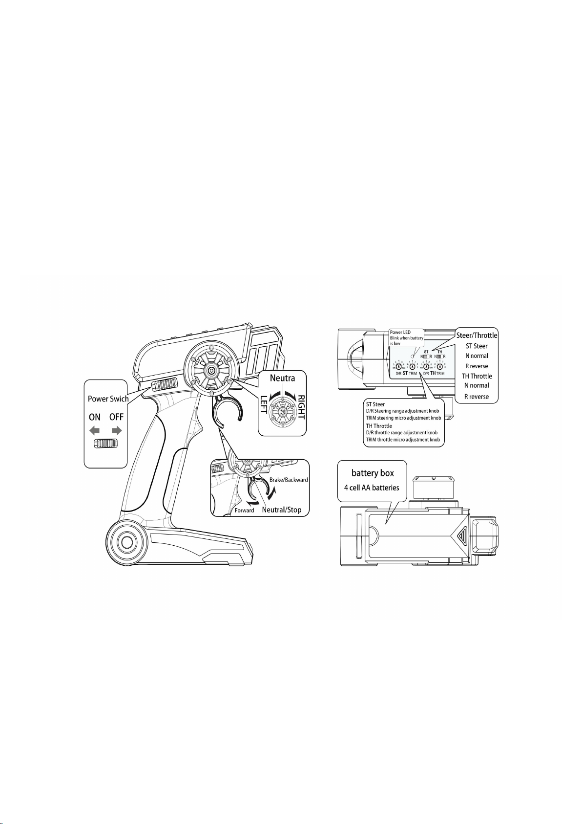
Transmitter
WARNING:ONLY ALKALINE BATTERIES CAN BE USED. MAKE SURE
MATCH THE POLARITY (+/-) AS SHOWN ON THE BATTERIES.
INCORRECT INSTALLATION OF BATTERIES WILL HARM THE RADIO
SYSTEM.
Page 3
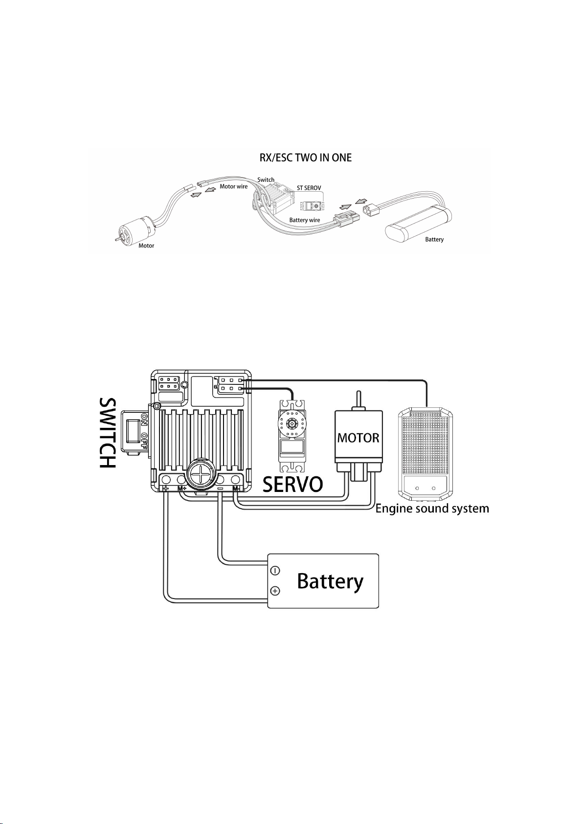
Receiver
Connections
WARNING:MAKE SURE MATCH THE POLARITY (+/-) AS SHOWN ON
THE BATTERIES. INCORRECT INSTALLATION OF BATTERIES WILL
HARM THE FS-2REE!!!
2in1 interface
Page 4

ON/OFF:Battery switch.
+/-:Battery connector, range 6-12.6V.
M+/M-:Motor connector. Max current 60A.
ST:Steering signal output, it provides steering engine power supply and PWM
signal.
TH:Throttle signal output and bind set, it provides power supply and throttle
PWM signal.
LiPo | NiMH:Battery type selection between Lipo and NiMH.
Fwd/Rr/Bev | Fwd/Rev:Running mode selection between Fwd/Rr/Bev and
Fwd/Rev.
Set the Parameters
Using the jumper cap to set running mode and battery type.
Battery Type: LiPo/NiMH,the “LiPo” is the default option。
Running Mode: Fwd/Rev/Br and Fwd/Rev. The “Fwd/Rev/Br” is the default
option.
Fwd=Forward, Br=Brake, Rev=Reverse
The“Fwd / Br / Rev” mode indicates the vehicle can go forward, backward and
brake. This mode uses “Double-click” method to make the vehicle reverse. When
moving the throttle stick from the neutral zone to backward zone for the 1st time, the
ESC begins to brake the motor and the motor slows down and stop, so the backward
action is NOT performed immediately. When the throttle stick is moved to the
backward zone again, the backward action will happen.
The “Fwd / Rev” mode uses “Single-click” method to make the vehicle reverse,
when moving the throttle stick from neutral zone to backward zone, the vehicle
reverses immediately, so this mode is usually used for rock crawler.
Transmitter and Receiver Pairing
Transmitter has been already paired with receiver and ready to use. If user is
Page 5

going to replace for the receiver, follow the steps below for the pairing:
Turn on transmitter. Connect the “S” and “-” of TH channel output. Then turn on
the receiver, the LED light on the receiver should be fast blink, within 5 seconds LED
light should stay on, pairing complete.
Receiver LED light State
1. LED light stays on: transmitter and receiver has been paired, work properly.
2. LED light off: receiver does not pick a signal from transmitter: 1. transmitter is not
on; 2. pairing has not been done yet.
3. LDE light blink once a second: battery voltage is low.
4. LED light keeps fast blink: under pairing mode.
Beep Meaning
1 Short beep: The battery is NiMH.
2 short beeps: The battery is 2S Lipo.
3 short beeps: The battery is 3S Lipo.
1 long beep: the ESC is ready to run.
Fail Safe
Fail safe feature build in receiver. When receiver stop communication with
transmitter, ESC will stop outputting, then steering channel output will maintain the
latest position.
Low Voltage Warning
Low voltage warning feature build in receiver.
If the voltage of battery is lower than 3.3V per series(LiPo) or 5.3V total(NiMH),
the ESC will enter the protection mode, so the motor max speed will be limited to
50%.
If the voltage of battery is lower than 3 V per series(LiPo) or 5V total(NiMH),
the car will stop.
Installation and Use Guide
The remote control is a 2.4G wireless products, a proper installation and usage
will exert influence on performance of the product.
Due to the poor penetration of 2.4G signals, it is necessary to ensure that
transmitters and receivers are used without occlusions in order to ensure reliable
communication;
A build-in 2.4G signal receiving module inside the receiver, so keep it away as
far as possible from other electronic products, motors, etc., to reduce interference;
A build-in antenna is inside the transmitter of the remote controller. The antenna is
vertically installed. So keep the remote controller in a vertical position when using;
The remote controller receiver has an antenna, ensure that the antenna keep vertical
position to the ground during the installation, and keep any metal materials away near
the antenna.
Page 6

As the radio frequency products are affected by the external environment, the
performance differences vary greatly. The main points of installation and use are to
ensure that the RF signals of the remote controller can be transmitted effectively and
reliably.
Proper installation and use are essential to ensure product performance.
Summary: FS-2EE radio system is a high performance and multiple
functions for RC cars. The built-in receiver and ESC make FS-2EE become a
high degree of integration with complex functions product, please be sure to
carefully read the user manual in using, avoid wiring error caused damage to the
product.
Transmitter troubleshooting
Troubles
Possible Causes
Solutions
After power on,
no LED lights up
Batteries are installed
abnormal; Battery low
Reinstall the batteries; change
the batteries
ESC troubleshooting
Troubles
Possible Causes
Solutions
After power on,
no LED lights up
No power is drawn to the
ESC; The switch is broken
Check the connections
between battery and ESC;
Re-solder the connector if
needed;Change the ESC
switch
Led off
The transmitter is closed;The
transmitter is not paired
Open the transmitter;Re-pair
the transmitter
Led blinks once a
second
Battery voltage is low.
Change battery.
The car runs
backwards when
accelerating
forward on the
transmitter
The direction setting of the
throttle channel is incorrect in
the transmitter or the motor
wires are wrongly connected
Reverse the direction of the
throttle channel; Swap the
wires between the ESC and
motor.
The vehicle can’t
reach to the full
speed.
Incorrect TH D/R setting;
Battery protect due to battery
low
Increase TH D/R; Change
battery
The vehicle can’t
motion, but the
Battery low cut-off protect;
The connection between ESC
Change battery; Check the
connection between the motor
Page 7

LED indicators
work normally
and motor is interrupted; The
motor is damaged
and ESC; Change battery.
The motor
accelerates
rapidly at the
startup moment,
but has lockout or
cogging problem.
The discharge capacity of the
battery is not strong enough;
The motor rotates too fast,
and the gear ratio is too
aggressive; Something wrong
with the driveline of the
vehicle.
Change a battery with better
discharge capability;
Use a motor with lower RPM,
or smaller pinion to soften the
gear ratio; Check the driveline
of the vehicle
Page 8

FCC STATEMENT :
This device complies with Part 15 of the FCC Rules. Operation is subject
to the following two conditions:
(1) This device may not cause harmful interference, and
(2) This device must accept any interference received, including
interference that may cause undesired operation.
Warning: Changes or modifications not expressly approved by the party
responsible for compliance could void the user's authority to operate the
equipment.
NOTE: This equipment has been tested and found to comply with the
limits for a Class B digital device, pursuant to Part 15 of the FCC Rules.
These limits are designed to provide reasonable protection against
harmful interference in a residential installation. This equipment
generates uses and can radiate radio frequency energy and, if not
installed and used in accordance with the instructions, may cause harmful
interference to radio communications. However, there is no guarantee
that interference will not occur in a particular installation. If this equipment
does cause harmful interference to radio or television reception, which
can be determined by turning the equipment off and on, the user is
encouraged to try to correct the interference by one or more of the
following measures:
Reorient or relocate the receiving antenna.
Increase the separation between the equipment and receiver.
Connect the equipment into an outlet on a circuit different from that to
which the receiver is connected.
Consult the dealer or an experienced radio/TV technician for help.
This device comply with FCC SAR requirements. The highest reported 1g-SAR for body is 0.339 W / Kg
 Loading...