

Page 1
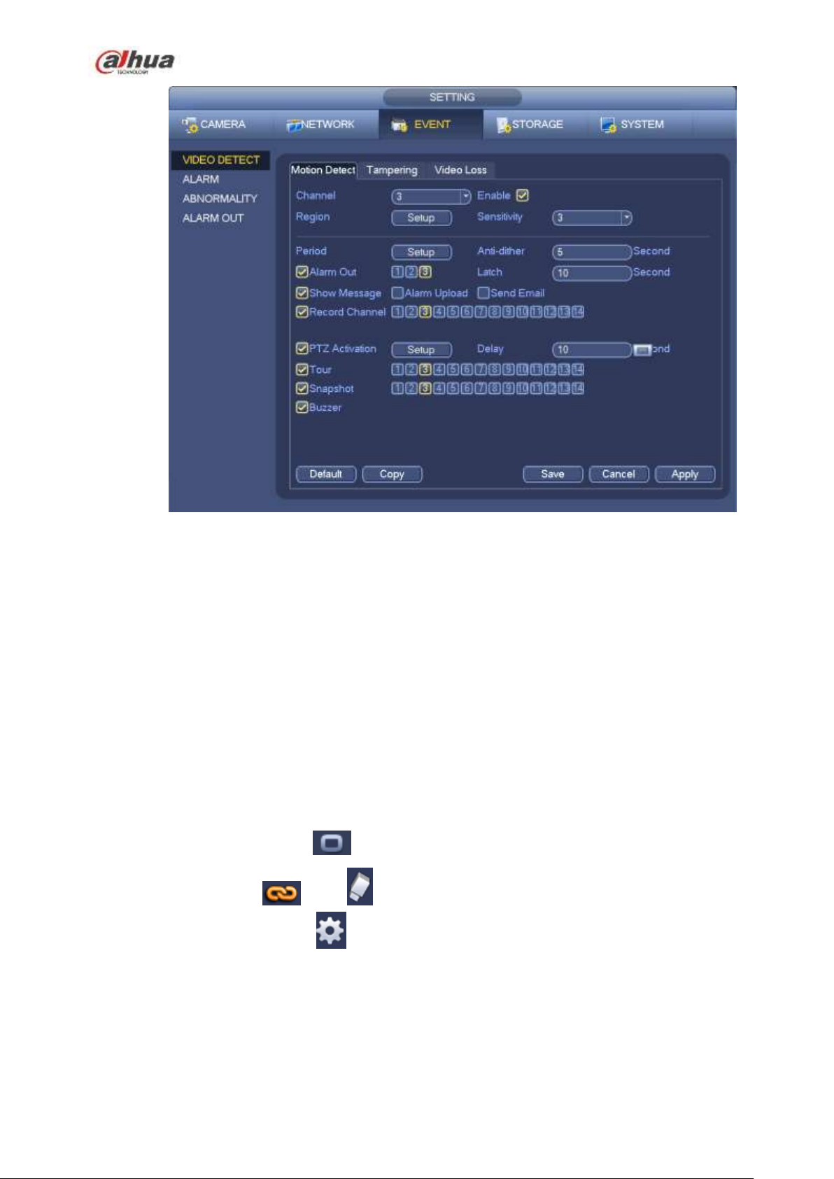
Figure 4-69
b) Select motion detect from the event type dropdown list. Select a channel from the dropdown list
and then check the enable button to enable motion detect function.
c) Click Region Select button to set motion detect zone. There are 396(PAL)/330(NTSC) small
zones. The green zone is current cursor position. Grey zone is the motion detection zone. Black
zone is the disarmed zone. You can click Fn button to switch between the arm mode and disarm
mode. In arm mode, you can click the direction buttons to move the green rectangle to set the
motion detection zone. After you completed the setup, please click ENTER button to exit current
setup. Do remember click save button to save current setup. If you click ESC button to exit the
region setup interface system will not save your zone setup.
d) Period: Click set button, you can see an interface is shown as in Figure 4-92. Here you can set
motion detect period. System only enables motion detect operation in the specified periods. It is
not for video loss or the tampering. There are two ways for you to set periods. Please note
system only supports 6 periods in one day.
In Figure 4-92, Select icon of several dates, all checked items can be edited together. Now
the icon is shown as . Click to delete a record type from one period.
In Figure 4-92. Click button after one date or a holiday, you can see an interface shown as in
Figure 4-93. There are four record types: regular, motion detection (MD), Alarm, MD & alarm.
e) Set sensitivity. Please note the sixth level has the highest sensitivity.
f) Click Save button to complete motion detect setup.
g) From Main menu->Setting->Storage->-Schedule. See Figure 4-63
h) Set motion detect record channel, period and the record type shall be motion detect (MD).
Please refer to chapter 4.10.2.
187
Page 2
i) Click Copy button to copy current setup to other channel(s).
j) Click OK button to complete motion detect record setup.
Figure 4-70
Figure 4-71
4.10.3.2 Motion Detect Snapshot
a) From Main menu->Setting->Camera->Encode->Snapshot, you can go to snapshot interface.
See Figure 4-72.
b) In Figure 4-72, select trigger snapshot from the dropdown list and then set picture size, quality
and snapshot frequency. Click OK button to save current setup.
c) From Main menu->Setting->Event->Detect, here you can select motion detect type, motion
detect channel and then check the enable box. Please refer to chapter 4.10.3.1.
d) Click OK button to complete motion detect setup.
188
Page 3
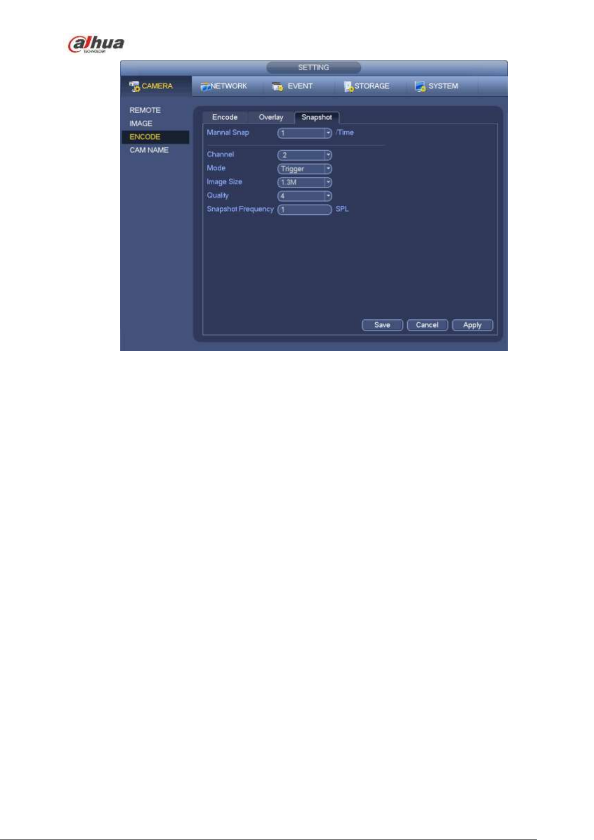
Figure 4-72
4.10.4 Alarm Record/Snapshot
4.10.4.1 Alarm Record
a) Before you set alarm setup information, please go to chapter 2.3 to connect alarm input and
alarm output cable (such as light, siren and etc).
b) The record priority is: Alarm>Motion detect>Regular.
In the main menu, from Setting->Event-> Alarm, you can see alarm setup interface. See Figure 4-73.
Alarm in: Here is for you to select channel number.
Event type: There are four types. Local input/network input/IPC external/IPC offline alarm.
Local input alarm: The alarm signal system detects from the alarm input port.
Network input alarm: It is the alarm signal from the network.
IPC external alarm: It is the on-off alarm signal from the front-end device and can activate the
local NVR.
IPC offline alarm: Once you select this item, system can generate an alarm when the front-end
IPC disconnects with the local NVR. The alarm can activate record, PTZ, snapshot and etc. The
alarm can last until the IPC and the NVR connection resumes.
Enable: Please you need to highlight this button to enable current function.
Type: normal open or normal close.
c) Click Save button to complete alarm setup interface.
189
Page 4

Figure 4-73
d) From Mani menu->Setting->Storage->Schedule, you can go to Figure 4-63.
e) Select alarm channel, period and the record type shall be alarm. Please refer to chapter 4.10.2.
f) Click Copy button to copy current setup to other channel(s).
g) Click OK button to save alarm record information.
4.10.4.2 Alarm Snapshot
a) Please refer to Step a) to step c) of chapter 4.10.3.2 to enable timing snapshot.
b) From Main menu->Setting->Storage->schedule, you can go to Figure 4-74 to enable snapshot
function.
c) From Main menu->Setting->Event->Alarm, you can go to Figure 4-73 to set alarm parameter
and enable snapshot function.
d) Click Save button to save alarm snapshot setup.
190
Page 5
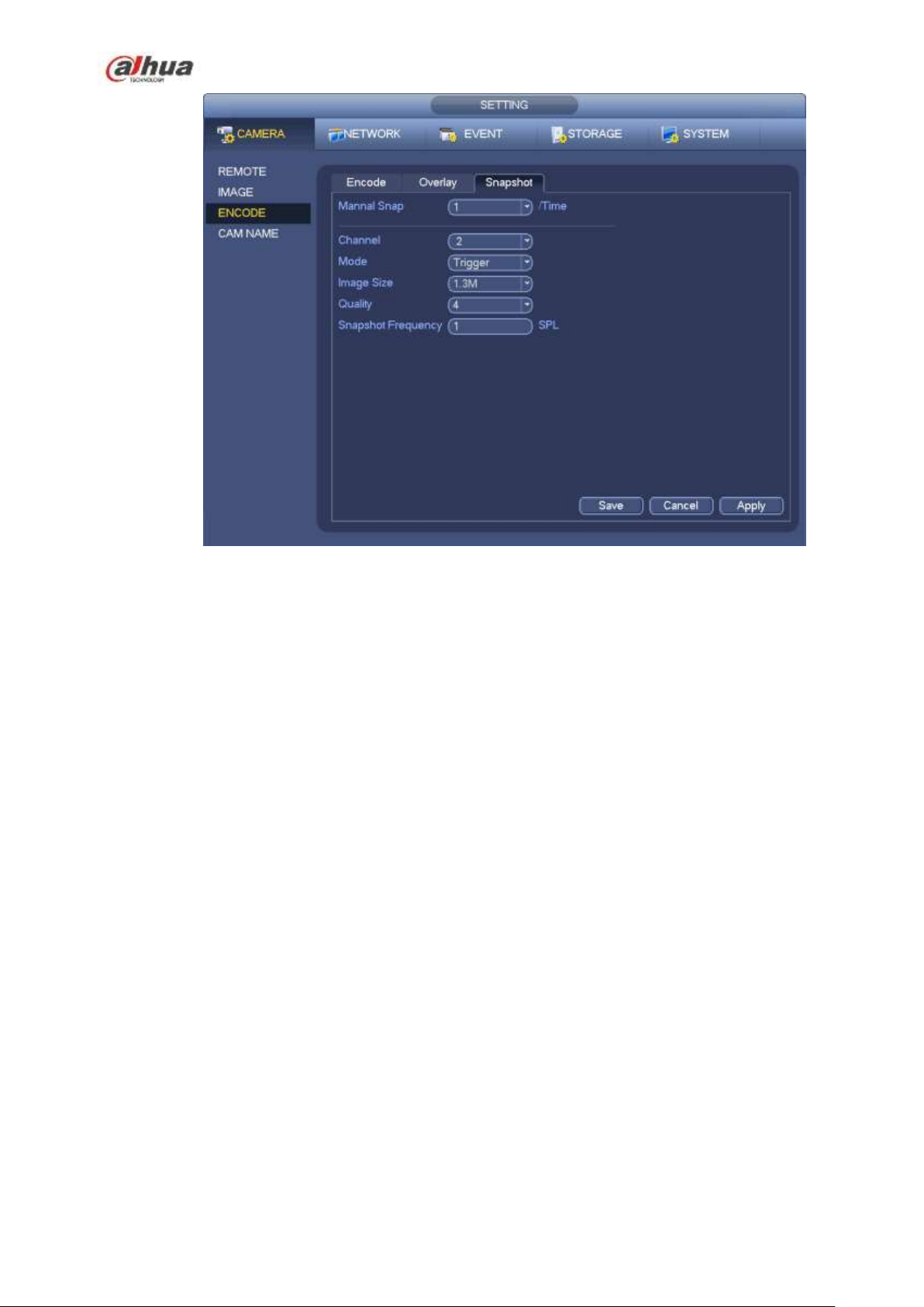
Figure 4-74
4.10.5 Manual Record/Snapshot
You need to have proper rights to implement the following operations. Please make sure the HDD
has been properly installed.
4.10.5.1 Manual Record
a) Right click mouse and select manual record or in the main menu, from
Setting->Storage->Manual Record. Manual record menu is shown as in Figure 4-75.
Tips
You can click Rec button on the front panel (if possible) to go to the Manual Record interface.
191
Page 6
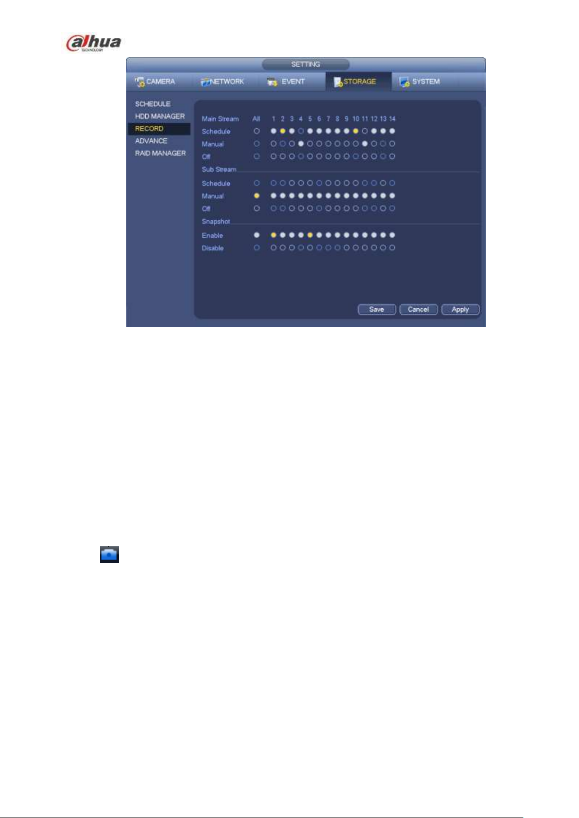
Figure 4-75
b) Check the box here to select manual record channel(s). You can see the corresponding
indicator light on the front panel is on.
Channel: It is to display device all channels.
Manual: It has the highest priority. Enable corresponding channel to record no matter what period
applied in the record setup. Now system is record general file.
Auto: System enables auto record function as you set in chapter 4.10.2 schedule interface
(General/Motion detect/Alarm)
Stop: Stop current channel record/Snapshot no matter what period applied in the record setup.
All: Check the All box to select all channels.
c) Click OK button to complete manual record setup.
4.10.5.2 Manual Snapshot
Click button at the preview control bar, you can snapshot 1-5 picture(s). From main
menu->Setting->Camera->Encode->Snapshot, you can set snapshot times. You can go to chapter 4.11 to
view snapshot picture.
4.10.6 Holiday Record/Snapshot
It is for you to set holiday record or snapshot plan. Please note the holiday record/snapshot setup has the
higher priority than the ordinary date record/snapshot setup.
4.10.6.1 Holiday Record
a) From Mani menu->Setting->System->General, you can go to the following interface. See Figure
4-76.
192
Page 7
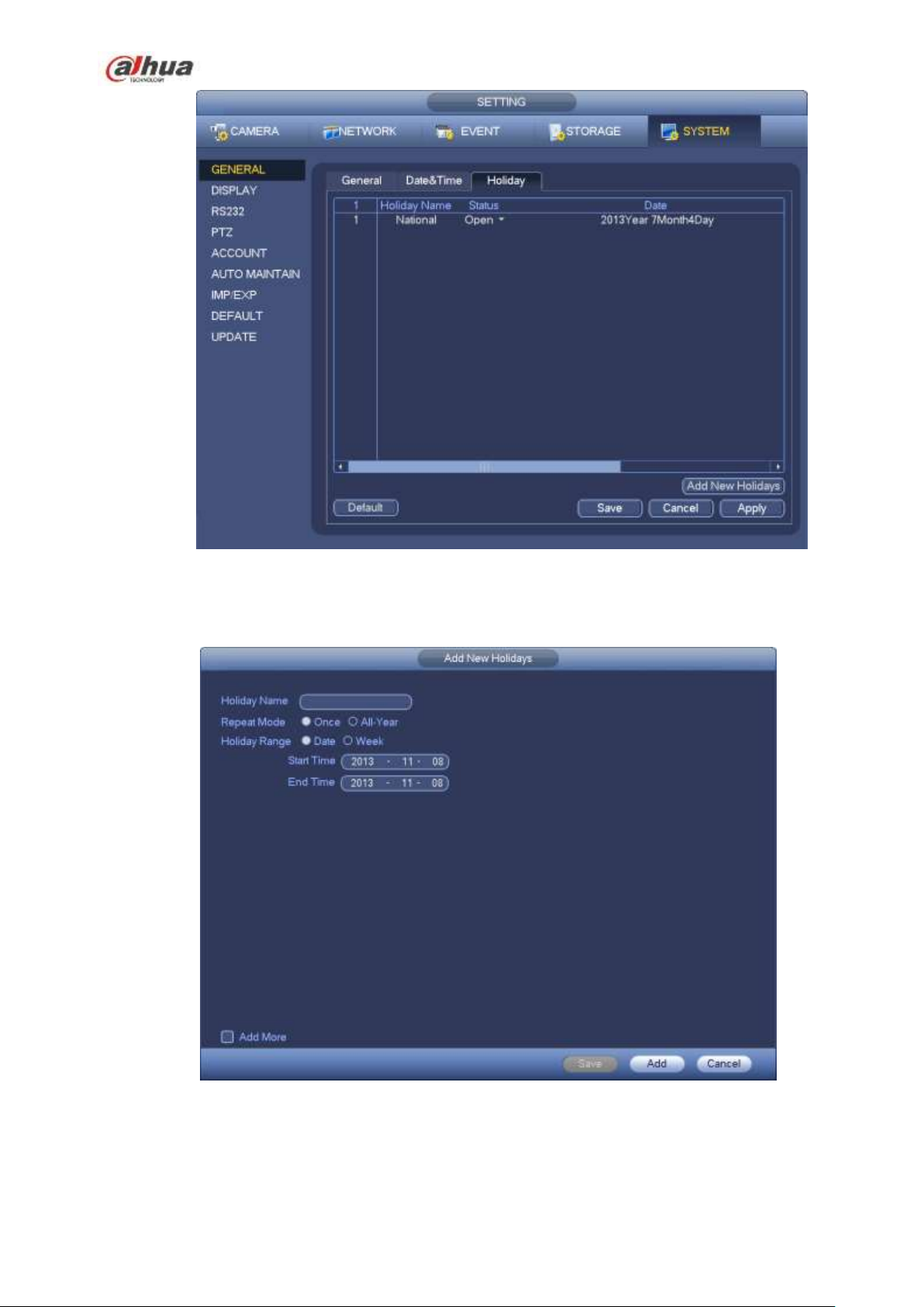
Figure 4-76
b) Click Add new holiday button, you can see an interface shown as in Figure 4-77. Here you can
set holiday date name, repeat mode, start time/end time and etc.
Figure 4-77
c) Click Add button to complete holiday setup. Now you can enable holiday setup and then click
Apply button.
d) From Main menu->setting->Storage->schedule, you can go to schedule interface. See Figure
193
Page 8
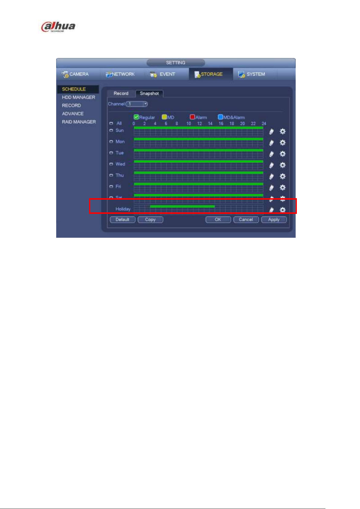
4-78. Now you can set period and record type of holiday time. Please refer to chapter 4.10.2.1
for detailed setup information.
Figure 4-78
e) Click OK button to set holiday record setup.
4.10.6.2 Holiday Snapshot
Set Holiday date first. Please refer to step a) to step c) of chapter 4.10.6.1.
From Main menu->Setting->Storage->Schedule, you can go to schedule interface. See Figure 4-78. Click
Holiday item to set snapshot period.
Set holiday snapshot type (Trigger/Regular). Please refer to chapter 4.10.2.2 or chapter 4.10.3.2.
4.10.7 Other Record/Snapshot
Motion detect&Alarm record or snapshot, please refer to chapter 4.10.4.
Video loss or tampering record or snapshot function, please refer to chapter 4.10.3.
4.11 Playback and Search
4.11.1 Real-time Playback
Please refer to chapter 4.7.2 for real-time playback information.
4.11.2 Search Interface
From Main menu->Search, or on the preview interface right click mouse and then select search item, you
can go to the following interface. See Figure 4-79.
194
Page 9

SN
Name
Function
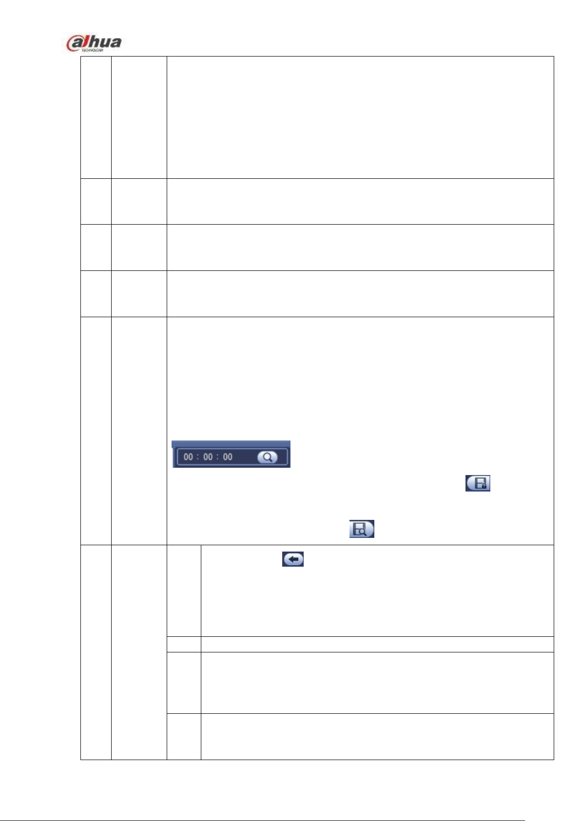
1
Display
window
Here is to display the searched picture or file.
Support 1/4/9/16-window playback. (It depends on the product channel
amount).
2
Search
type
Here you can select to search the picture or the recorded file.
You can select to play from the read-write HDD, from peripheral device or from
redundancy HDD.
Before you select to play from the peripheral device, please connect the
corresponding peripheral device. You can view all record files of the root directory
of the peripheral device. Click the Browse button; you can select the file you want to
play.
Important
Redundancy HDD does not support picture backup function, but it
supports picture playback function. You can select to play from redundancy
HDD if there are pictures on the redundancy HDD.
3
Calendar
The blue highlighted date means there is picture or file. Otherwise, there is no
picture or file.
In any play mode, click the date you want to see, you can see the
corresponding record file trace in the time bar.
4
Playback
mode
and
Playback mode:1/4/9/16. (It may vary due to different series.)
In 1-window playback mode: you can select 1-X channels (X depends on the
product channel amount).
Figure 4-79
Please refer to the following sheet for more information.
195
Page 10
channel
selection
pane.
In 4-window playback mode: you can select 4 channels according to your
requirement.
In 9-window playback mode, you can switch between 1-8, 9-16 and etc
channels.
In 16-window playback mode, you can switch between1-16, 17-32 and etc
channels.
The time bar will change once you modify the playback mode or the channel
option.
5
Card
number
search
The card number search interface is shown as below. Here you can view card
number/field setup bar. You can implement advanced search. Current series
product supports this function.
6
Face list
You can search when it is in 1-channel playback mode. Click it, system can filter all
human faces and generate human face list. Double click the file; system begins
playback the record or image of the corresponding human face.
7
Mark file
list button
Click it to go to mark file list interface. You can view all mark information of current
channel by time. Please refer to chapter 4.11.2.3 for detailed information.
Please note only the product of this icon supports mark function.
8
File list
switch
button
9
Playback
control
pane.
►/
Play/Pause
There are three ways for you to begin playback.
The play button
Double click the valid period of the time bar.
Double click the item in the file list.
In slow play mode, click it to switch between play/pause.
■
Stop
Backward play
In normal play mode, left click the button, the file begins backward play.
Click it again to pause current play.
In backward play mode, click ►/ to restore normal play.
│/
│
Double click it, you can view the picture/record file list of current day.
The file list is to display the first channel of the record file.
The system can display max 128 files in one time. Use the │and │ or the
mouse to view the file. Select one item, and then double click the mouse or click the
ENTER button to playback.
You can input the period in the following interface to begin accurate search.
File type:R—regular record; A—external alarm record;M—Motion detect
record.
Lock file. Click the file you want to lock and click the button to lock. The
file you locked will not be overwritten.
Search locked file: Click the button to view the locked file.
In playback mode, click it to play the next or the previous section. You can
click continuously when you are watching the files from the same channel.
In normal play mode, when you pause current play, you can click │ and
196
Page 11
│ to begin frame by frame playback.
In frame by frame playback mode, click ►/ to restore normal playback.
►
Slow play
In playback mode, click it to realize various slow play modes such as slow
play 1, slow play 2, and etc.
Fast forward
In playback mode, click to realize various fast play modes such as fast
play 1,fast play 2 and etc.
Note: The actual play speed has relationship with the software version.
Smart search
The volume of the playback
In 1-channel playback mode, click it to enable/disable display IVS rule
information on the video.
10
Time bar
It is to display the record type and its period in current search criteria.
In 4-window playback mode, there are corresponding four time bars. In other
playback mode, there is only one time bar.
Use the mouse to click one point of the color zone in the time bar, system
begins playback.
The time bar is beginning with 0 o'clock when you are setting the configuration.
The time bar zooms in the period of the current playback time when you are playing
the file.
The green color stands for the regular record file. The red color stands for the
external alarm record file. The yellow stands for the motion detect record file.
11
Time bar
unit
12
Backup
Select the file(s) you want to backup from the file list. You can check from the
list. Then click the backup button, now you can see the backup menu. System
Click the snapshot button in the full-screen mode, the system can snapshot
1 picture.
System supports custom snap picture saved path. Please connect the
peripheral device first, click snap button on the full-screen mode, you can
select or create path. Click Start button, the snapshot picture can be saved
to the specified path.
Mark button.
Please note this function is for some series product only. Please make sure
there is a mark button in the playback control pane.
You can refer to chapter 4.11.2.3 for detailed information.
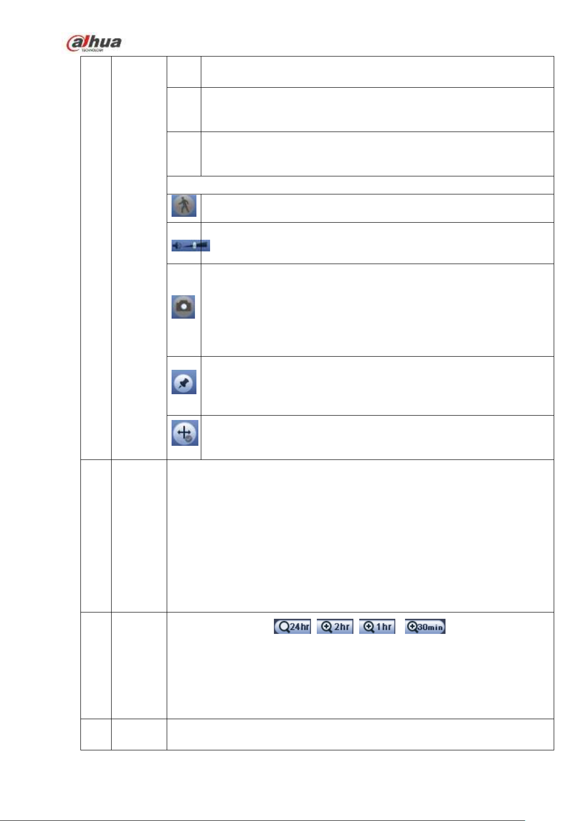
●The option includes: 、 、 和 ,. The smaller the unit,
the larger the zoom rate. You can accurately set the time in the time bar to playback
the record.
The time bar is beginning with 0 o'clock when you are setting the configuration.
The time bar zooms in the period of the current playback time when you are playing
the file.
197
Page 12
supports customized path setup. After select or create new folder, click the
Start button to begin the backup operation. The record file(s) will be saved in
the specified folder.
Check the file again you can cancel current selection. System max supports to
display 32 files from one channel.
After you clip on record file, click Backup button you can save it.
For one device, if there is a backup in process, you can not start a new backup
operation.
13
Clip
14
Record
type
In any play mode, the time bar will change once you modify the search type.
Other Functions
15
Smart
search
When system is playing, you can select a zone in the window to begin smart
search. Click the motion detect button to begin play.
Once the motion detect play has begun, click button again will terminate
current motion detect file play.
There is no motion detect zone by default.
If you select to play other file in the file list, system switches to motion detect
play of other file.
During the motion detect play process, you can not implement operations such
as change time bar, begin backward playback or frame by frame playback.
Please refer to chapter 4.11.2.1 Smart Search for detailed operation.
16
Other
channel
synchroni
zation
switch to
play
when
playback
When playing the file, click the number button, system can switch to the same
period of the corresponding channel to play.
It is to edit the file.
Please click to play the file you want to edit.
Select clip start time on the time bar and then Click to start clip.
Select clip stop time on the time bar and then click to stop clip.
Click , system pops up file backup dialogue box for you to save.
Please note:
Clip function is for one-channel mode/multiple-channel mode.
System max supports 1024 files backup at the same time.
You can not operate clip operation if there is any file has been checked in
the file list.
198
Page 13
17
Digital
zoom
When the system is in full-screen playback mode, left click the mouse in the
screen. Drag your mouse in the screen to select a section and then left click
mouse to realize digital zoom. You can right click mouse to exit.
18
Manually
switch
channel
when
playback
During the file playback process, you can switch to other channel via the
dropdown list or rolling the mouse.
This function is null if there is no record file or system is in smart search process.
Note:
All the operations here (such as playback speed, channel, time and progress) have relationship with
hardware version. Some series NVRs do not support some functions or playback speeds.
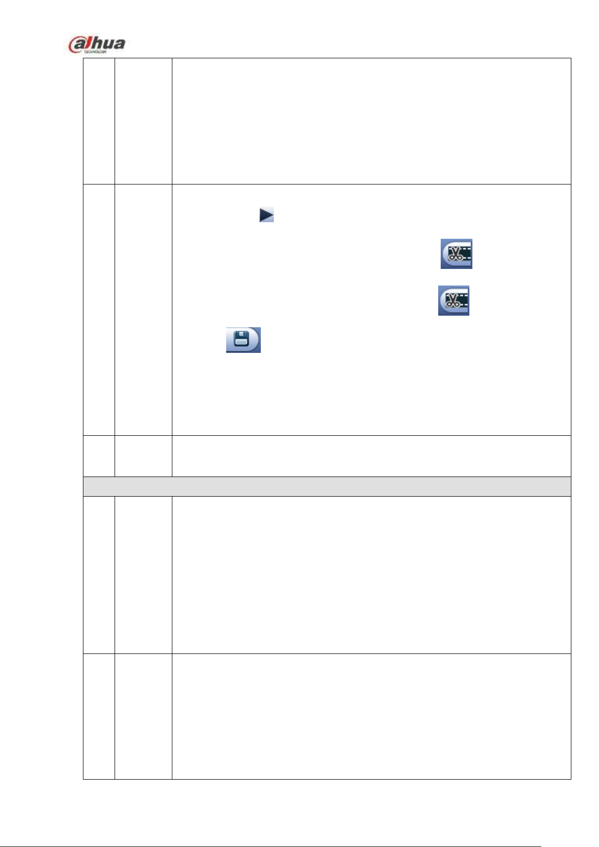
4.11.2.1 Smart Search
During the multiple-channel playback mode, double click one channel and then click the button,
system begins smart search. System supports 396(22*18 PAL) and 330(22*15 NTSC) zones. Please left
click mouse to select smart search zones. See Figure 4-80.
Figure 4-80
Click the , you can go to the smart search playback. Click it again, system stops smart search
playback.
Important
System does not support motion detect zone setup during the full-screen mode.
During the multiple-channel playback, system stops playback of rest channels if you
implement one-channel smart search.
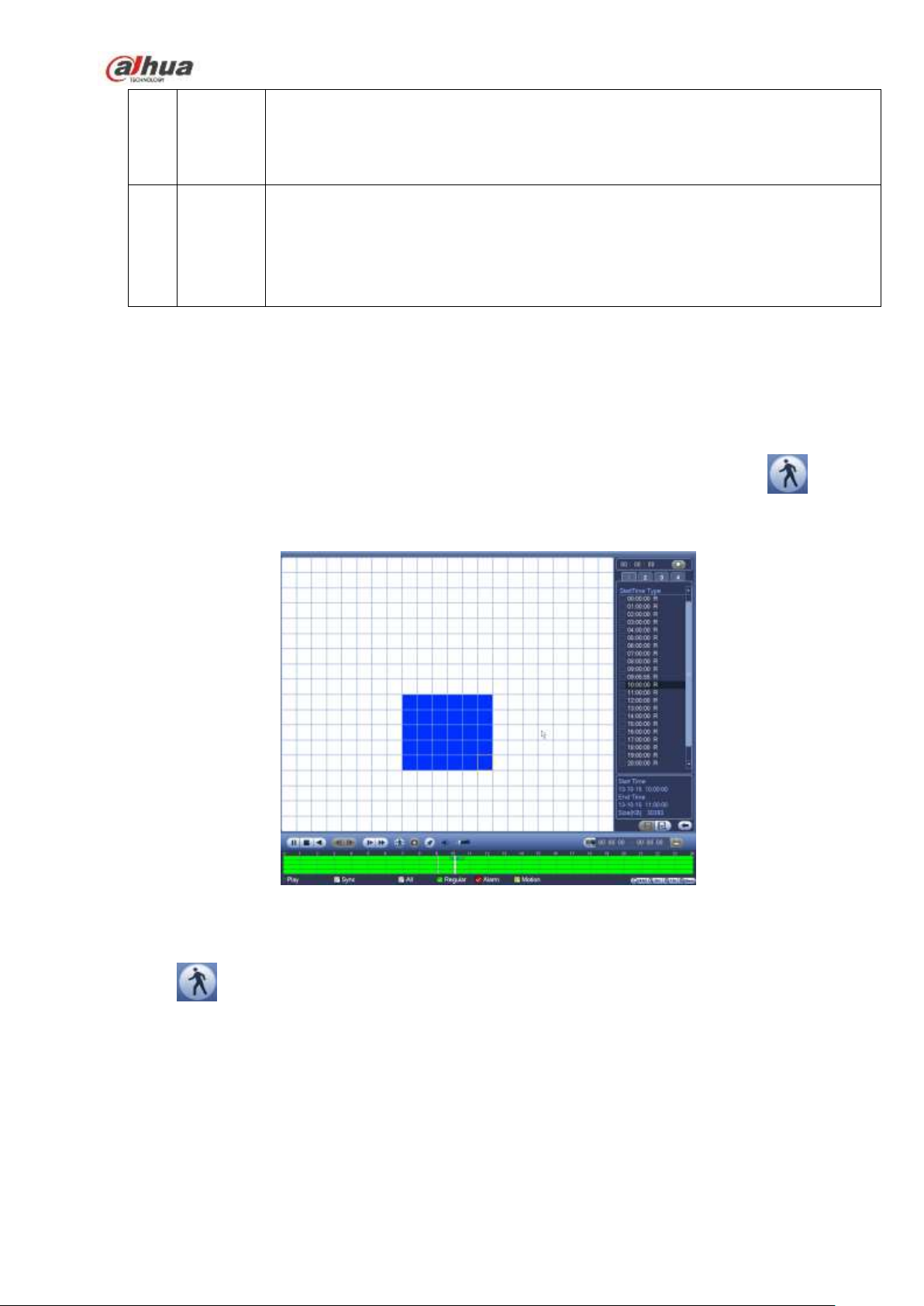
4.11.2.2 Accurate playback by time
Select records from one day, click the list, you can go to the file list interface. You can input time at the top
199
Page 14
right corner to search records by time. See image on the left side of the Figure 4-81 For example, input
time 11:00.00 and then click Search button , you can view all the record files after 11:00.00 (The
records includes current time.). See image on the right side of the Figure 4-81 Double click a file name to
playback.
Note
After you searched files, system implement accurate playback once you click Play for the first
time.
System does not support accurate playback for picture.
System supports synchronization playback and non-synchronous playback. The synchronization
playback supports all channels and non-synchronous playback only supports accurately
playback of current select channel.
Figure 4-81
4.11.2.3 Mark Playback
Please make sure your purchased device support this function. You can use this function only if
you can see the mark playback icon on the Search interface (Figure 4-79).
When you are playback record, you can mark the record when there is important information. After
playback, you can use time or the mark key words to search corresponding record and then play. It is very
easy for you to get the important video information.
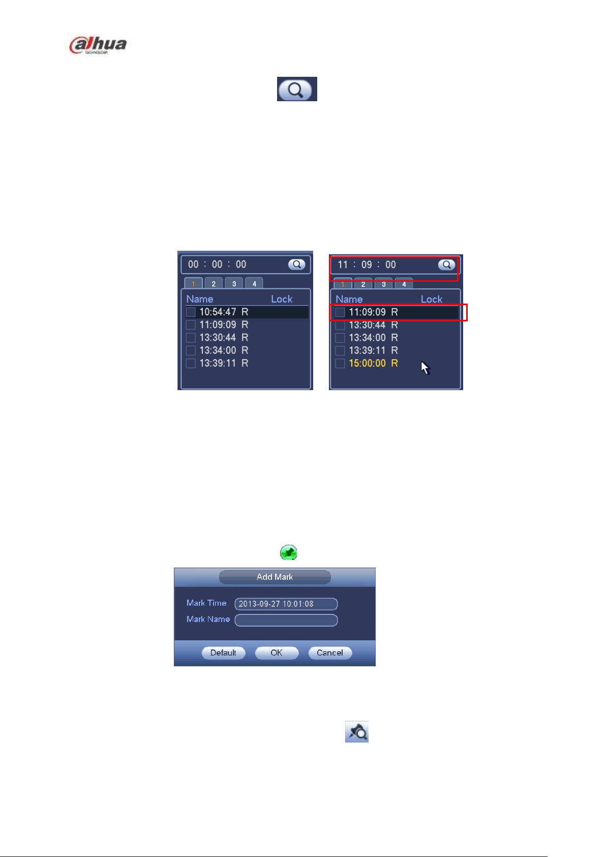
Add Mark
When system is playback, click Mark button , you can go to the following interface. See Figure 4-82.
Figure 4-82
Playback Mark
During 1-window playback mode, click mark file list button in Figure 4-79, you can go to mark file list
interface. Double click one mark file, you can begin playback from the mark time.
Play before mark time
200
Page 15

Here you can set to begin playback from previous N seconds of the mark time.
Note
Usually, system can playbacks previous N seconds record if there is such kind of record file. Otherwise,
system playbacks from the previous X seconds when there is such as kind of record.
Mark Manager
Click the mark manager button on the Search interface (Figure 4-79); you can go to Mark
Manager interface. See Figure 4-83. System can manage all the record mark information of current
channel by default. You can view all mark information of current channel by time.
Figure 4-83
Modify
Double click one mark information item, you can see system pops up a dialogue box for you to change
mark information. You can only change mark name here.
Delete
Here you can check the mark information item you want to delete and then click Delete button, you can
remove one mark item. .
Note
After you go to the mark management interface, system needs to pause current playback. System
resume playback after you exit mark management interface.
If the mark file you want to playback has been removed, system begin playbacking from the first file
in the list.
4.11.3 Picture Playback
a) From Main menu->Search, or on the preview interface right click mouse, you can go to Figure
4-79.
b) At the top right pane, you can check the box to select picture and then select playback interval.
c) Please refer to chapter 4.11.2 to select picture you want to view.
201
Page 16
4.12 Backup
4.12.1 File Backup
In this interface, you can backup record file to the USB device.
a) Connect USB burner, USB device or portable HDD and etc to the device.
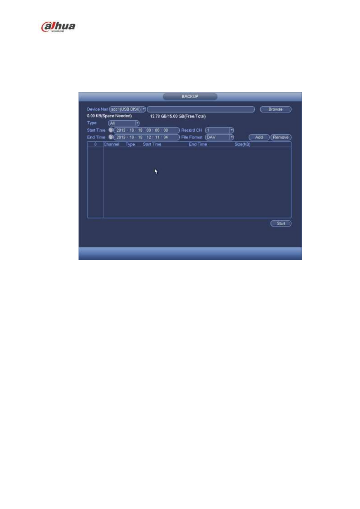
b) From Main menu->Backup, you can go to the Backup interface. See Figure 4-84
Figure 4-84
c) Select backup device and then set channel, file start time and end time.
d) Click add button, system begins search. All matched files are listed below. System automatically
calculates the capacity needed and remained. See Figure 4-85.
e) System only backup files with a √ before channel name. You can use Fn or cancel button to
delete √ after file serial number.
f) Click backup button, you can backup selected files. There is a process bar for you reference.
g) When the system completes backup, you can see a dialogue box prompting successful backup.
202
Page 17
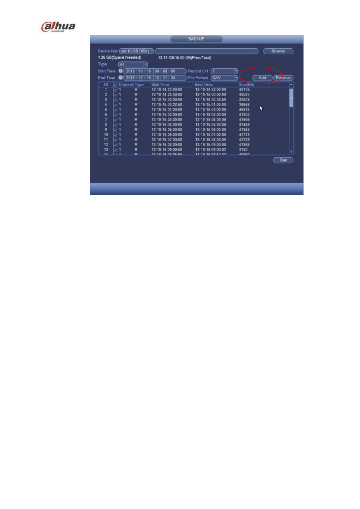
Figure 4-85
h) Click backup button, system begins burning. At the same time, the backup button becomes stop
button. You can view the remaining time and process bar at the left bottom.
Note
During backup process, you can click ESC to exit current interface for other operation (For
some series product only). The system will not terminate backup process.
The file name format usually is: Channel number+Record type+Time. In the file name, the
YDM format is Y+M+D+H+M+S. File extension name is .dav.
4.12.2 Import/Export
This function allows you to copy current system configuration to other devices. It also supports import,
create new folder, and delete folder and etc function.
From Main menu->Setting->System->Import/Export, you can see the configuration file backup interface is
shown as below. See Figure 4-86.
203
Page 18
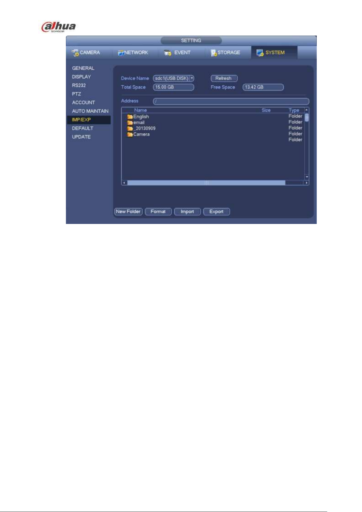
Figure 4-86
Export: Please connect the peripheral device first and then go to the following interface. Click
Export button, you can see there is a corresponding ―Config_Time‖ folder. Double click the folder,
you can view some backup files.
Import: Here you can import the configuration files from the peripheral device to current device. You
need to select a folder first. You can see a dialogue box asking you to select a folder if you are
selecting a file. System pops up a dialogue box if there is no configuration file under current folder.
After successfully import, system needs to reboot to activate new setup.
Format: Click Format button, system pops up a dialogue box for you to confirm current operation.
System begins format process after you click the OK button.
Note:
System can not open config backup interface again if there is backup operation in the process.
System refreshes device when you go to the config backup every time and set current directory as
the root directory of the peripheral device.
If you go to the configuration backup interface first and then insert the peripheral device, please click
Refresh button to see the newly added device.
4.12.3 Backup Log
a) From Main menu->Info->Log, the interface is shown as below. See Figure 4-87.
204
Page 19
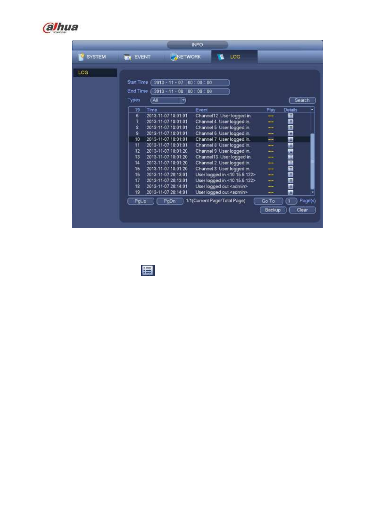
Figure 4-87
b) Select log type and then set start time/end time, click Search button, you can see log time and
event information. Click to view detailed log information.
c) Select log items you want to save and then click backup button, you can select a folder to save
them. Click Start to backup and you can see the corresponding dialogue box after the process is
finish.
4.12.4 USB Device Auto Pop-up
After you inserted the USB device, system can auto detect it and pop up the following dialogue box. It
allows you to conveniently backup file, log, configuration or update system. See Figure 4-88. Please refer
to chapter 4.12.1 file backup, chapter 4.12.3 backup log, chapter 4.12.2 import/export, and chapter 4.11.2
search for detailed information.
205
Page 20

Figure 4-88
4.13 Alarm
4.13.1 Detect Alarm
In the main menu, from Setting to Detect, you can see motion detect interface. See Figure 4-89.There
are three detection types: motion detection, video loss, tampering.
4.13.1.1 Motion Detect
After analysis video, system can generate a motion detect alarm when the detected moving signal
reached the sensitivity you set here.
Detection menu is shown as below. See Figure 4-89.
Event type: From the dropdown list you can select motion detection type.
Channel: Select a channel from the dropdown list to set motion detect function.
Enable: Check the box here to enable motion detect function.
Region: Click select button, the interface is shown as in Figure 4-90. Here you can set motion
detection zone. There are four zones for you to set. Please select a zone first and then left drag the
mouse to select a zone. The corresponding color zone displays different detection zone. You can
click Fn button to switch between the arm mode and disarm mode. In arm mode, you can click the
direction buttons to move the green rectangle to set the motion detection zone. After you completed
the setup, please click ENTER button to exit current setup. Do remember click save button to save
current setup. If you click ESC button to exit the region setup interface system will not save your
zone setup.
Sensitivity: System supports 6 levels. The sixth level has the highest sensitivity.
Anti-dither: Here you can set anti-dither time. The value ranges from 5 to 600s. The anti-dither time
refers to the alarm signal lasts time. It can be seem as the alarm signal activation stays such as the
buzzer, tour, PTZ activation, snapshot, channel record. The stay time here does not include the latch
time. During the alarm process, the alarm signal can begin an anti-dither time if system detects the
local alarm again. The screen prompt, alarm upload, email and etc will not be activated. For example,
if you set the anti-dither time as 10 second, you can see the each activation may last 10s if the local
alarm is activated. During the process, if system detects another local alarm signal at the fifth
second, the buzzer, tour, PTZ activation, snapshot, record channel will begin another 10s while the
206
Page 21

screen prompt, alarm upload, email will not be activated again. After 10s, if system detects another
alarm signal, it can generate an alarm since the anti-dither time is out.
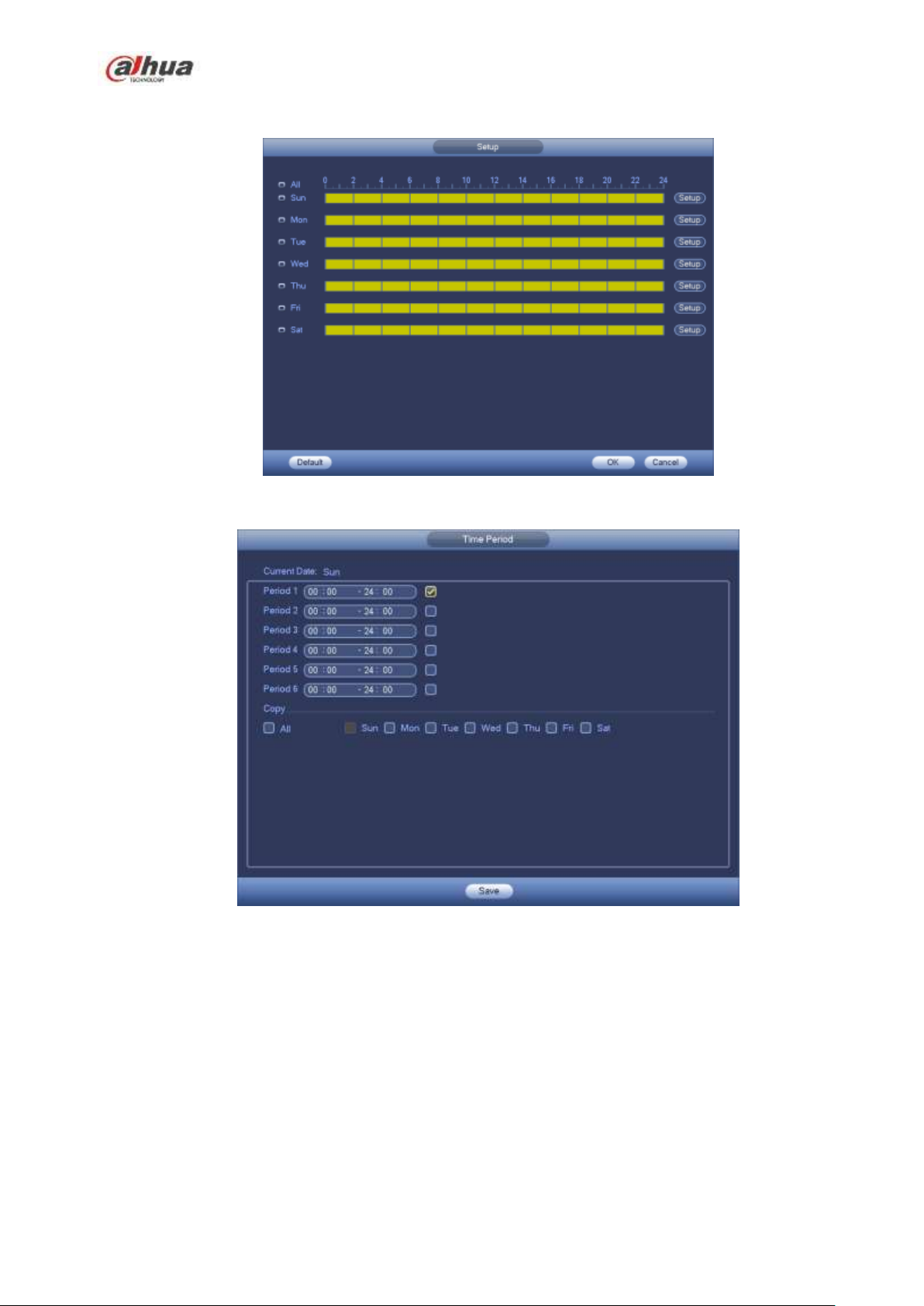
Period: Click set button, you can see an interface is shown as in Figure 4-92. Here you can set
motion detect period. System only enables motion detect operation in the specified periods. It is not
for video loss or the tampering. There are two ways for you to set periods. Please note system only
supports 6 periods in one day.
In Figure 4-92, Select icon of several dates, all checked items can be edited together. Now
the icon is shown as . Click to delete a record type from one period.
In Figure 4-92. Click button after one date or a holiday, you can see an interface shown as in
Figure 4-93. There are four record types: regular, motion detection (MD), Alarm, MD & alarm.
Alarm output: when an alarm occurs, system enables peripheral alarm devices.
Latch: when motion detection complete, system auto delays detecting for a specified time. The value
ranges from 1-300(Unit: second)
Show message: System can pop up a message to alarm you in the local host screen if you enabled
this function.
Alarm upload: System can upload the alarm signal to the network (including alarm centre) if you
enabled current function.
Send email: System can send out email to alert you when an alarm occurs.
Record channel: System auto activates motion detection channel(s) to record once an alarm occurs.
Please make sure you have set MD record in Schedule interface(Main Menu->Setting->Schedule)
and schedule record in manual record interface(Main Menu->Advanced->Manual Record)
PTZ activation: Here you can set PTZ movement when an alarm occurs. Such as go to preset, tour
&pattern when there is an alarm. Click ―select‖ button, you can see an interface is shown as in Figure
4-91X.
Record Delay: System can delay the record for specified time after alarm ended. The value ranges
from 10s to 300s.
Tour: Here you can enable tour function when alarm occurs. System one-window tour.
Snapshot: You can enable this function to snapshoot image when a motion detect alarm occurs.
Video matrix Check the box here to enable this function. When an alarm occurs, SPOT OUT port
displays device video output. It displays video (1-window tour) from alarm activation channel you
select at the Record channel item.
Buzzer: Highlight the icon to enable this function. The buzzer beeps when alarm occurs.
Please highlight icon to select the corresponding function. After all the setups please click save
button, system goes back to the previous menu.
Note:
In motion detection mode, you can not use copy/paste to set channel setup since the video in each
channel may not be the same.
In Figure 4-90, you can left click mouse and then drag it to set a region for motion detection. Click Fn to
switch between arm/withdraw motion detection. After setting, click enter button to exit.
207
Page 22
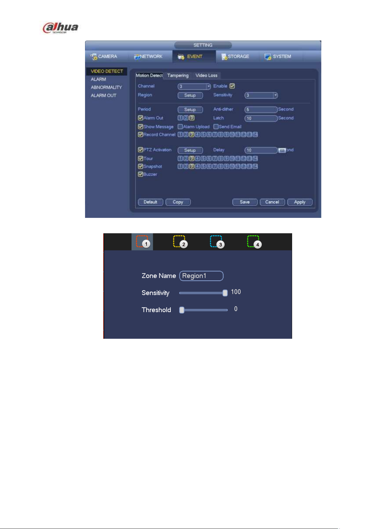
Figure 4-89
Figure 4-90
208
Page 23
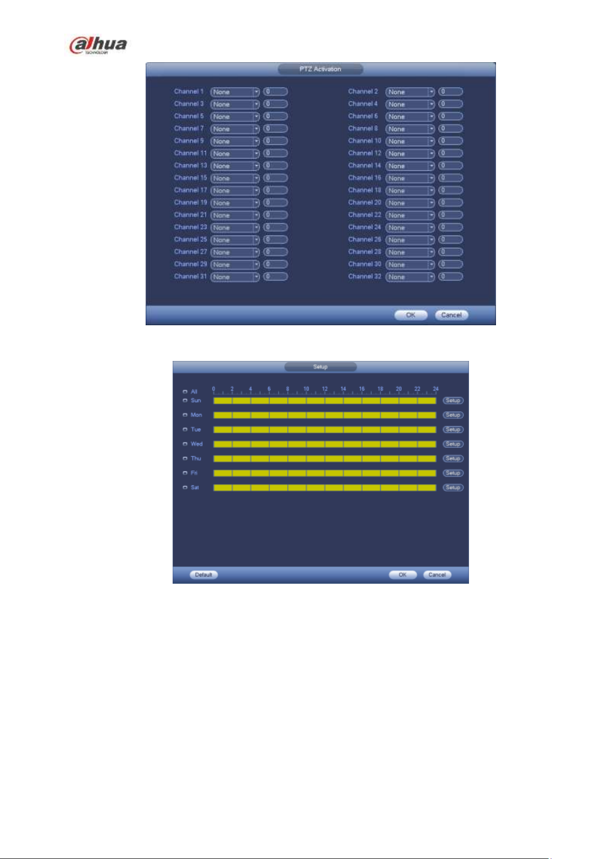
Figure 4-91
Figure 4-92
209
Page 24
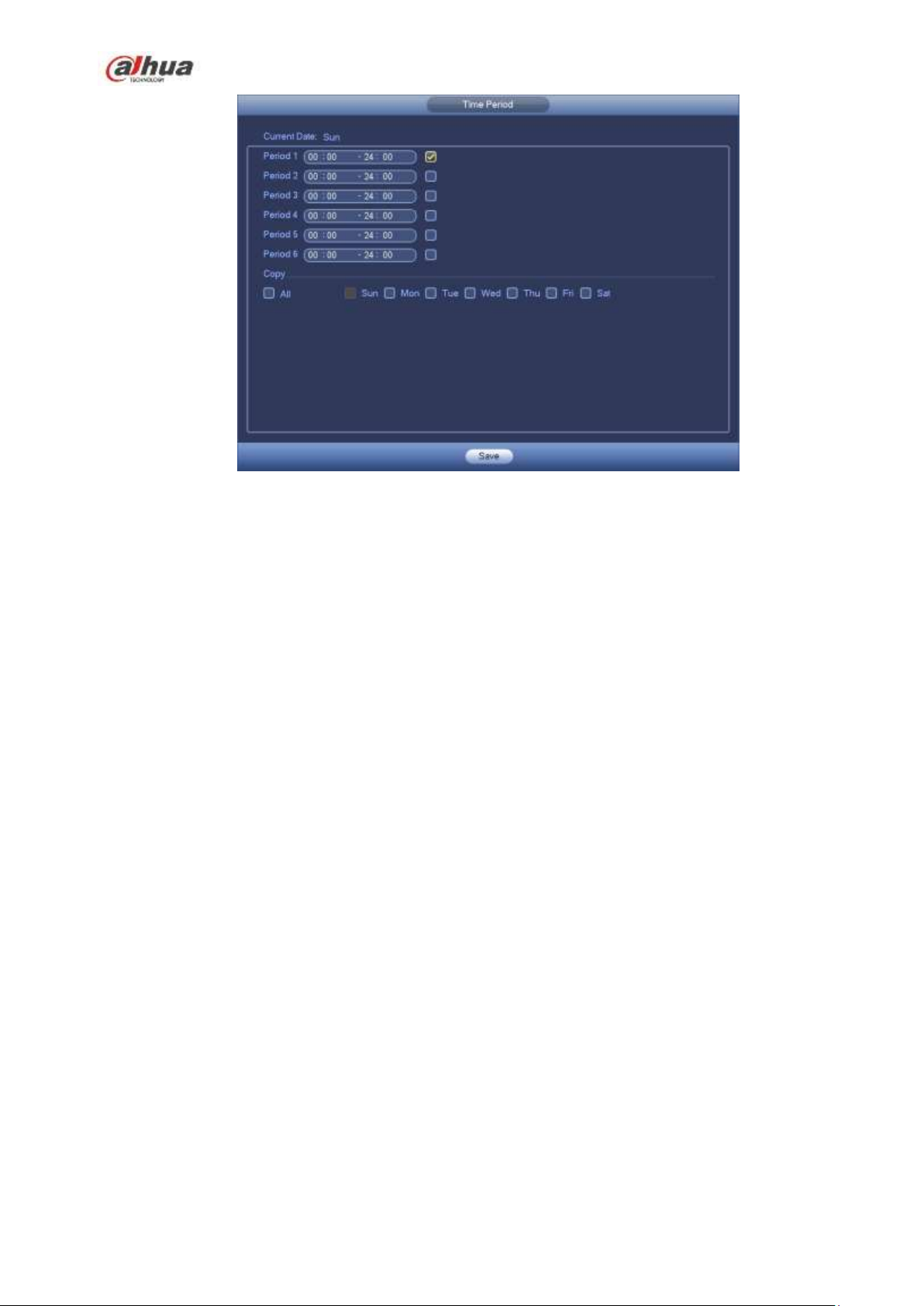
Figure 4-93
Motion detect here only has relationship with the sensitivity and region setup. It has no relationship
with other setups.
4.13.1.2 Tampering
When someone viciously masks the lens, or the output video is in one-color due to the environments
light change, the system can alert you to guarantee video continuity. Tampering interface is shown as
in Figure 4-94. You can enable ―Alarm output ―or ―Show message‖ function when tampering alarm
occurs.
Sensitivity: The value ranges from 1 to 6. It mainly concerns the brightness. The level 6 has the
higher sensitivity than level 1. The default setup is 3.
Tips:
You can enable preset/tour/pattern activation operation when video loss occurs.
Please refer to chapter 4.13.1.1 motion detection for detailed information.
Note:
In Detect interface, copy/paste function is only valid for the same type, which means you can not
copy a channel setup in video loss mode to tampering mode.
About Default function. Since detection channel and detection type may not be the same, system
can only restore default setup of current detect type. For example, if you click Default button at
the tampering interface, you can only restore default tampering setup. It is null for other detect
types.
System only enables tampering function during the period you set here. It is null for motion detect
or video loss type.
210
Page 25
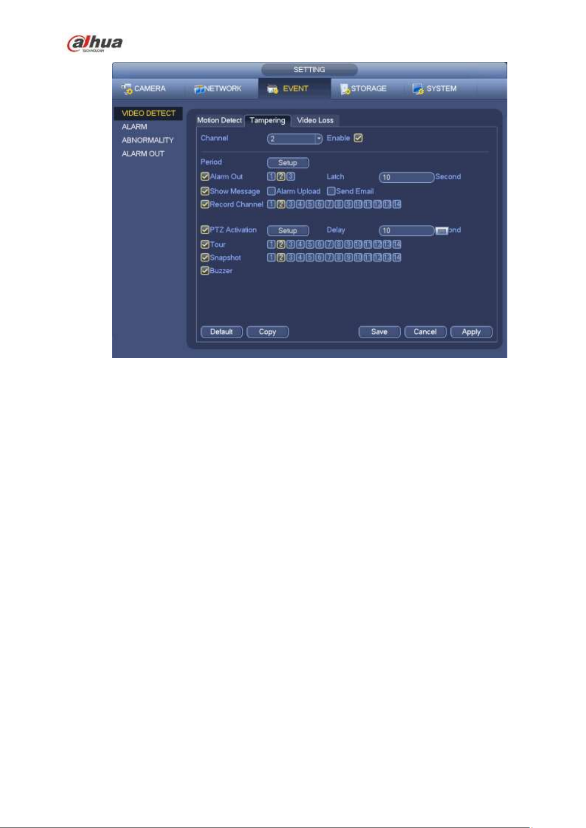
Figure 4-94
4.13.1.3 Video Loss
In Figure 4-89, select video loss from the type list. You can see the interface is shown as in Figure
4-95. This function allows you to be informed when video loss phenomenon occurred. You can
enable alarm output channel and then enable show message function.
You can refer to chapter 4.13.1.1Motion detect for detailed information.
Tips:
You can enable preset/tour/pattern activation operation when video loss occurs.
211
Page 26
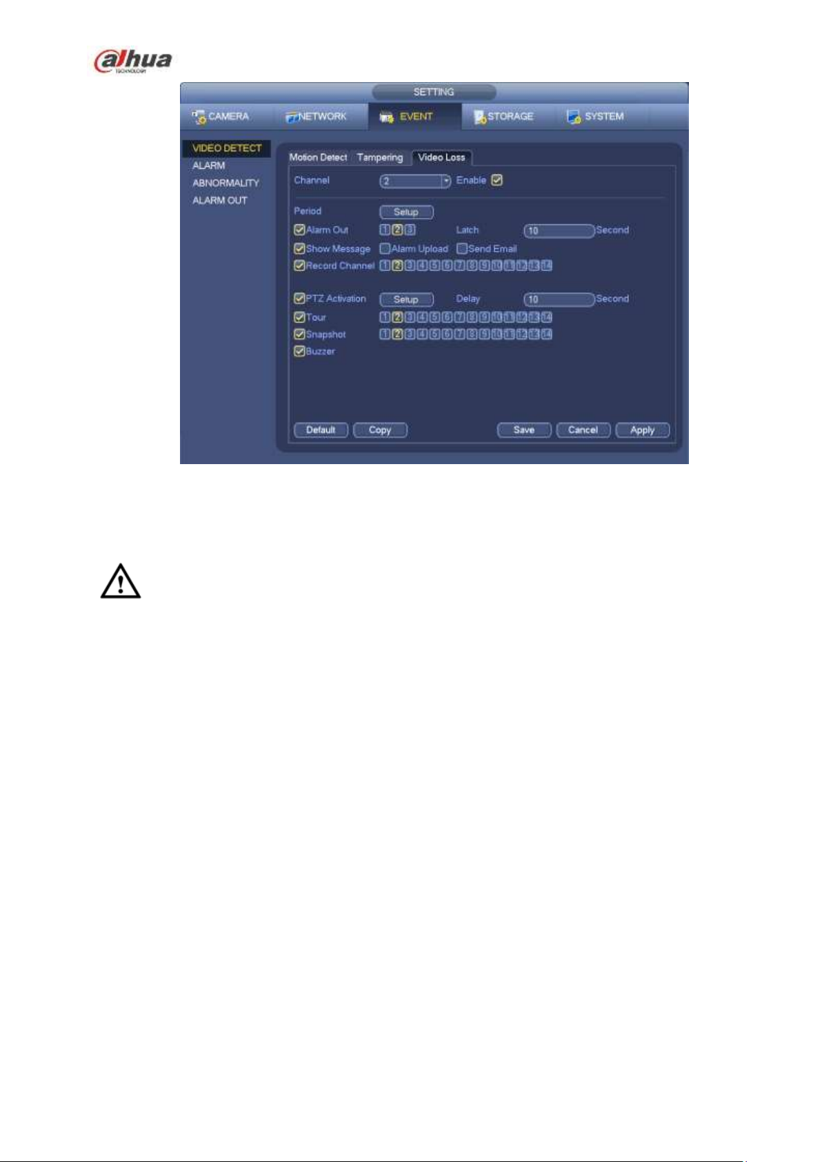
Figure 4-95
4.13.2 IVS (Optional)
Please make sure you are connecting to the smart network camera, otherwise you can not
use IVS function!
From main menu->Setting->Event, you can go to the IVS interface. It includes four interfaces:
Tripwire/intrusion/object/scene.
4.13.2.1 Tripwire (Optional)
Please make sure you are connecting to the smart network camera, otherwise you can not use
IVS function!
System generates an alarm once there is any object crossing the tripwire in the specified direction.
From main menu->Setting->Event->IVS->Tripwire, the interface is shown as below. See Figure 4-96.
212
Page 27
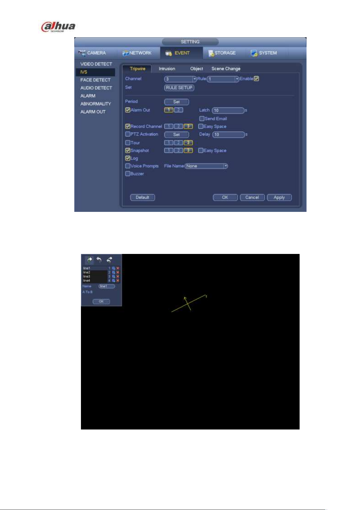
Figure 4-96
Check the Enable box to enable tripwire function.
Click Rule setup to draw the tripwire. See Figure 4-97.
Figure 4-97
Select SN (Line1/2/3/4) and direction, and then input customized rule name.
Line1/2/3/4: System supports four tripwires. Each SN stands for one tripwire.
213
Page 28
Direction ( / / ): System can generate an alarm once there is any object crossing in the
specified direction.
Now you can draw a rule. Left click mouse to draw a tripwire. The tripwire can be a direct line, curve or
polygon. Right click mouse to complete.
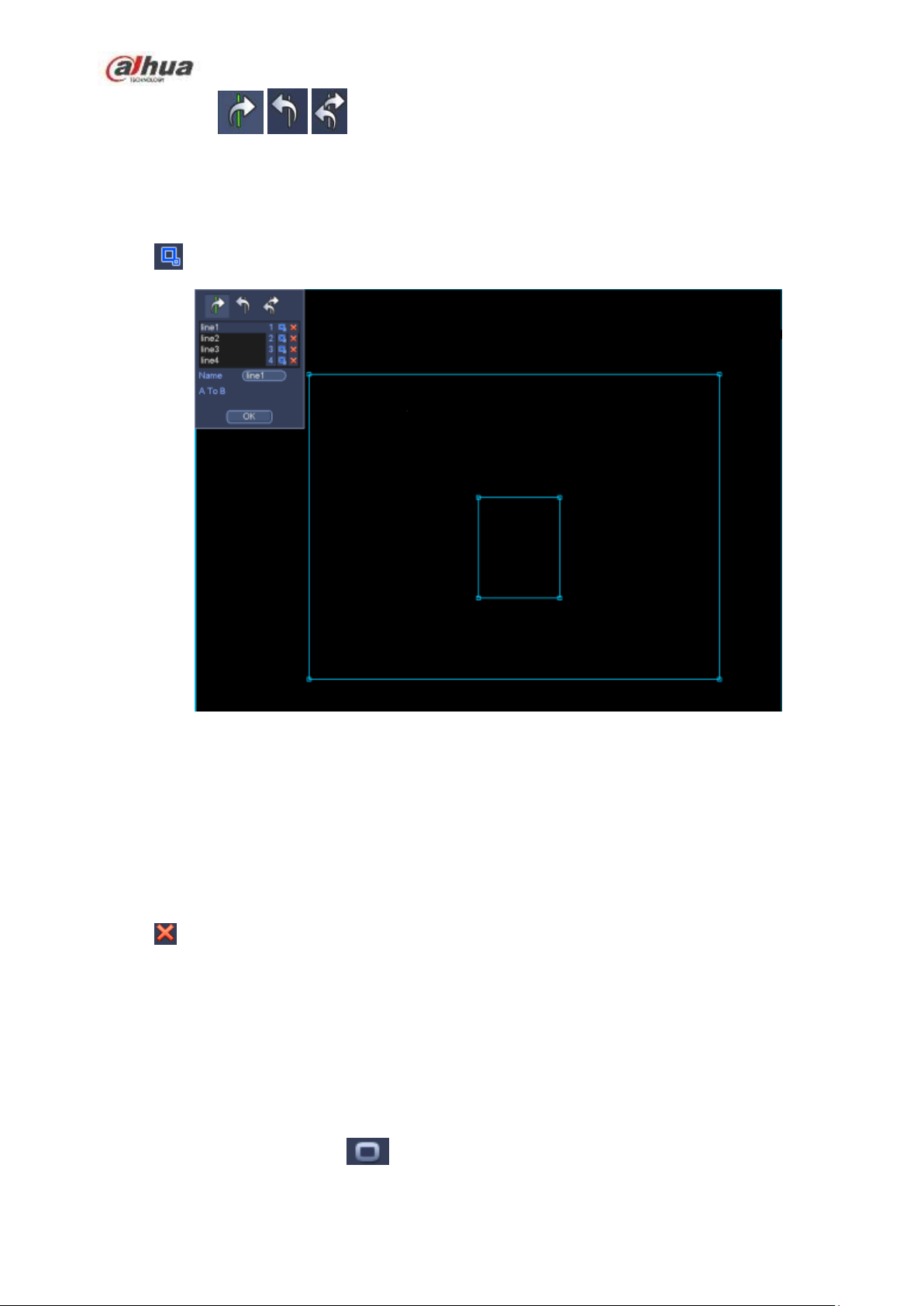
Click to draw filter object.
Figure 4-98
Select the blue line and then use mouse to adjust zone size.
Note
Each rule can set two sizes (min size/max size). Once the object is smaller than the min size or larger
than the max size, there is no alarm. Please make sure the max size is larger than the min size.
Click Ok to complete the rule setup.
Tips
Click to delete the corresponding rule.
You can refer to the following information to set other parameters.
Channel: Select a channel from the dropdown list to set tripwire function.
Enable: Check the box here to enable tripwire function.
Rule: input customized rule name here.
Period: Click set button, you can see an interface is shown as in Figure 4-92. Here you can set
tripwire period. System only enables tripwire operation in the specified periods. There are two ways
for you to set periods. Please note system only supports 6 periods in one day.
In Figure 4-92, Select icon of several dates, all checked items can be edited together. Now
214
Page 29
the icon is shown as . Click to delete a record type from one period.
In Figure 4-92. Click button after one date or a holiday, you can see an interface shown as in
Figure 4-93.
Alarm output: when an alarm occurs, system enables peripheral alarm devices.
Latch: when tripwire complete, system auto delays detecting for a specified time. The value ranges
from 1-300(Unit: second)
Show message: System can pop up a message to alarm you in the local host screen if you enabled
this function.
Alarm upload: System can upload the alarm signal to the network (including alarm centre) if you
enabled current function.
Send email: System can send out email to alert you when an alarm occurs.
Record channel: System auto activates tripwire channel(s) to record once an alarm occurs. Please
make sure you have set intelligent record in Schedule interface(Main Menu->Setting->Schedule)
and schedule record in manual record interface(Main Menu->Advanced->Manual Record)
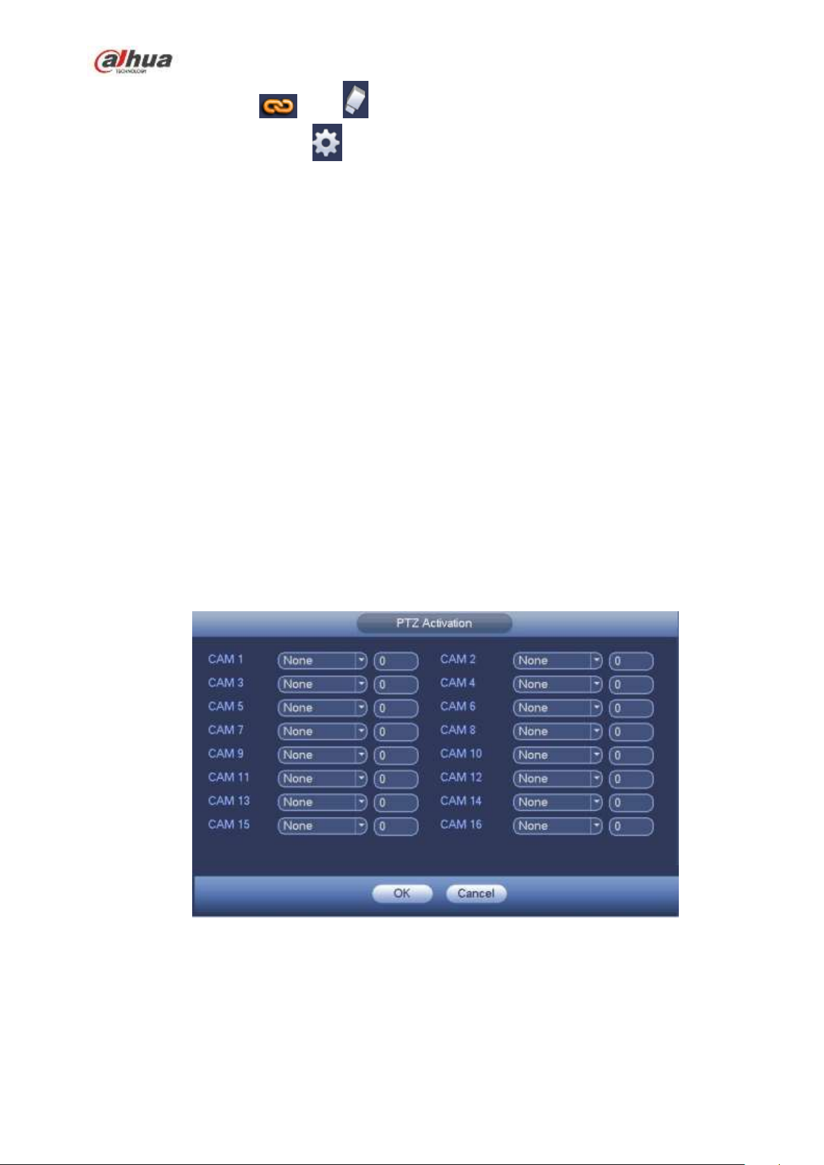
PTZ activation: Here you can set PTZ movement when an alarm occurs. Such as go to preset, tour
&pattern when there is an alarm. Click “select” button, you can see an interface is shown as in
Figure 4-91X.
Record Delay: System can delay the record for specified time after alarm ended. The value ranges
from 10s to 300s.
Tour: Here you can enable tour function when an alarm occurs. System one-window tour.
Snapshot: You can enable this function to snapshot image when a motion detect alarm occurs.
Buzzer: Highlight the icon to enable this function. The buzzer beeps when an alarm occurs.
Figure 4-99
215
Page 30
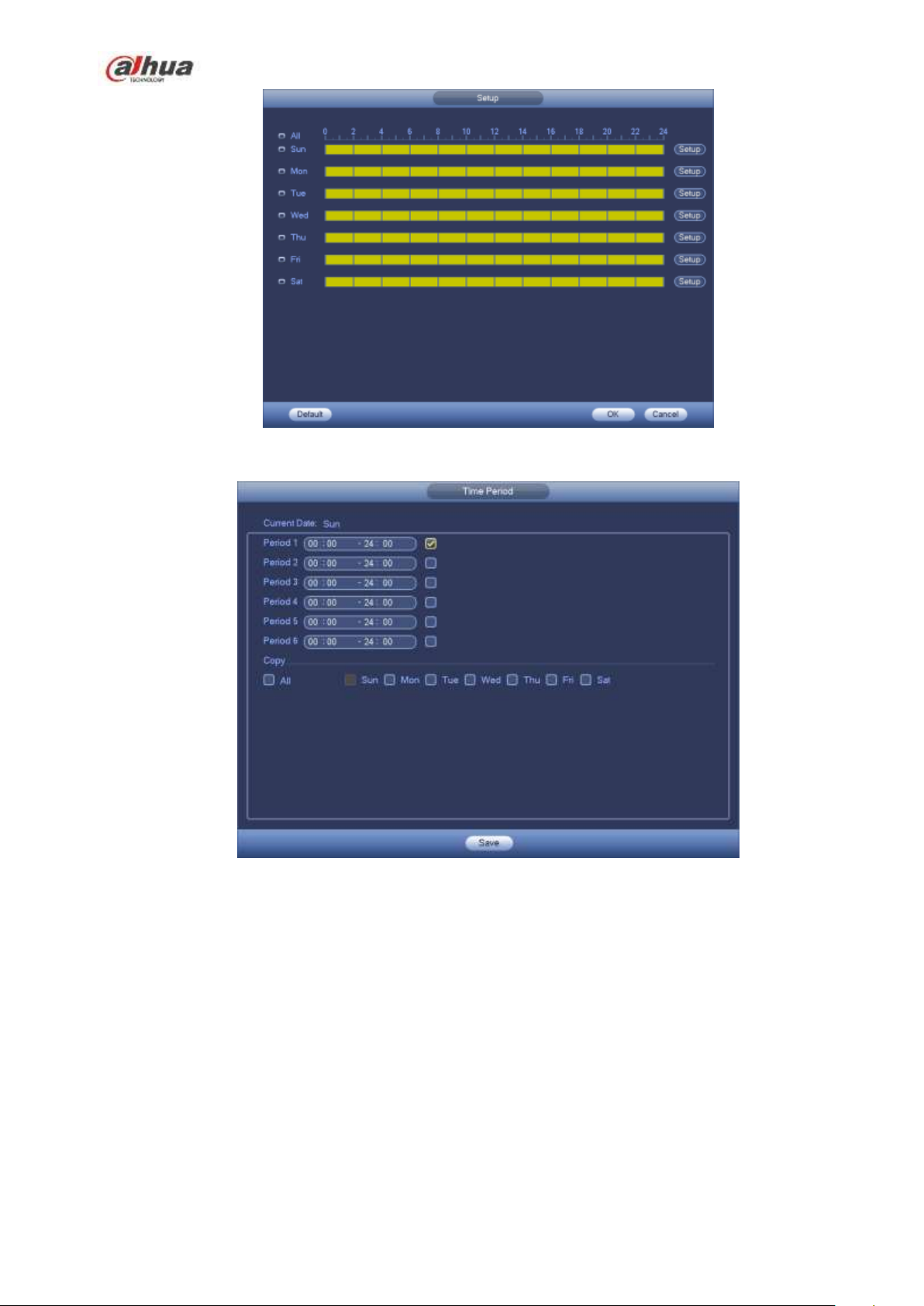
Figure 4-100
Figure 4-101
4.13.2.2 Intrusion (Cross warning zone) (Optional)
Please make sure you are connecting to the smart network camera, otherwise you can not use
IVS function!
System generates an alarm once there is any object entering or exiting the zone in the specified direction.
From main menu->Setting->Event->IVS->Intrusion, the intrusion interface is shown as below. See Figure
4-102.
216
Page 31

Figure 4-102
Check the enable box to enable intrusion function.
Click Rule setup to draw the zone. See Figure 4-103.
Figure 4-103
Select SN (Area1/2/3/4) and direction, and then input customized rule name.
Area1/2/3/4: System supports four zones. Each SN stands for one zone.
Direction ( / / ): System can generate an alarm once there is any object
enter/exit (Or both) the zone.
Now you can draw a rule. Left click mouse to draw a line first and then right click mouse to draw another
line until you draw a rectangle, you can right click mouse to exit.
Click Ok to complete the rule setup.
Tips
217
Page 32

Click to delete the corresponding rule.
You can refer to the chapter 4.13.2.1 to set parameters.
4.13.2.3 Object Detect (Optional)
Please make sure you are connecting to the smart network camera, otherwise you can not
use IVS function!
For the same channel, the object detect and the intrusion can not be valid at the same time.
System generates an alarm when the object missing/abandoned object alarm occurs.
From main menu->Setting->Event->IVS->Object, the object interface is shown as below. See Figure
4-104.
Figure 4-104
Check the enable box to enable object detect function.
Click Rule setup to draw the rule.
Figure 4-105
218
Page 33

Select SN (object1/2/3/4) and direction, and then input customized rule name.
Object1/2/3/4: System supports four zones. Each SN stands for one zone.
Direction ( / ): For icon , system can generate an alarm once the object left in the
one for the specified time.. For icon , system can generate an alarm once the object is out of
the zone for the specified time.
Period: It refers to the object in/out the zone time.
Now you can draw a rule. Left click mouse to draw a line, until you draw a rectangle, you can right click
mouse.
Click Ok to complete the rule setup.
Tips
Click to delete the corresponding rule.
You can refer to the chapter 4.13.2.1 to set parameters.
4.13.2.4 Scene Change (Optional)
Please make sure you are connecting to the smart network camera, otherwise you can not use
IVS function!
When the detected scene changes, system can generate an alarm.
From main menu->Setting->Event->IVS->Scene change, the interface is shown as in Figure 4-106.
Figure 4-106
You can refer to the chapter 4.13.2.1 to set parameters.
219
Page 34

4.13.3 Face Detect (Optional)
Please make sure you are connecting to the smart network camera, otherwise you can not
use IVS function!
When camera detects human face, system can generate an alarm.
From main menu->Setting->Event->Face detect, the interface is shown as in Figure 4-107.
Face ROI: Check the box here, system can enhance the human face display pane.
Log: Check the box here, system can record face detect log.
You can refer to the chapter 4.13.2.1 t to set other parameters.
Figure 4-107
4.13.4 Audio Detect (Optional)
Please make sure you are connecting to the smart network camera, otherwise you can not
use IVS function!
System can generate an alarm once it detect the audio input is abnormal or audio volume changes.
From main menu->Setting->Event->Audio detect, you can see an interface shown as in Figure 4-108.
Input abnormal: Check the box here, system can generate an alarm once the audio input is
abnormal.
Intensity change: Check the box here, system can generate an alarm once the audio volume
becomes strong.
Sensitivity: It refers to the audio recognition sensitivity. The higher the value is, the higher the
sensitivity is.
220
Page 35

Threshold: It is to set intensity change threshold. The smaller the value is, the higher the sensitivity
is.
Log: Check the box here, system can record audio detect alarm log.
You can refer to the chapter 4.13.2.1 t to set other parameters.
Figure 4-108
4.13.5 Alarm output
From Main menu->Setting->Event->Alarm output, you can see an interface shown as in Figure 4-109.
Here is for you to set proper alarm output (Auto/manual/stop).
Click OK button of the alarm reset, you can clear all alarm output status.
221
Page 36

Figure 4-109
Please highlight icon to select the corresponding alarm output.
After all the setups please click OK button, system goes back to the previous menu.
4.13.6 Alarm Setup
In the main menu, from Setting->Event->Alarm, you can see alarm setup interface.
Alarm in: Here is for you to select channel number.
In the main menu, from Setting->Event->Alarm, you can see alarm setup interface. See Figure 4-110.
There are four alarm types. See Figure 4-110 to Figure 4-113.
Local alarm: The alarm signal system detects from the alarm input port.
Network alarm: It is the alarm signal from the network.
IPC external alarm: It is the on-off alarm signal from the front-end device and can activate the local
HNVR.
IPC offline alarm: Once you select this item, system can generate an alarm when the front-end IPC
disconnects with the local HNVR. The alarm can activate record, PTZ, snap and etc. The alarm can
last until the IPC and the HNVR connection resumes.
Important
If it is your first time to boot up the device, the disconnection status of the front-end
network camera will not be regarded as offline. After one successfully connection, all
the disconnection events will be regarded as IPC offline event.
When IPC offline alarm occurs, the record and snapshot function of digital channel is
null.
Enable: Please you need to highlight this button to enable current function.
Type: normal open or normal close.
Period: Click set button, you can see an interface is shown as in Figure 4-115. There are two ways
for you to set periods. There are max 6 periods in one day. There are four record types: regular,
motion detection (MD), Alarm, MD & alarm.
In Figure 4-115, Select icon of several dates, all checked items can be edited together.
Now the icon is shown as . Click to delete a record type from one period.
In Figure 4-115. Click button after one date or a holiday, you can see an interface shown
as in Figure 4-116. There are four record types: regular, motion detection (MD), Alarm, MD &
alarm.
PTZ activation: When an alarm occurred, system can activate the PTZ operation. The PTZ activation
lasts an anti-dither period. See Figure 4-114.
Anti-dither: Here you can set anti-dither time. The value ranges from 5 to 600s. The anti-dither time
refers to the alarm signal lasts time. It can be seem as the alarm signal activation stays such as the
buzzer, tour, PTZ activation, snapshot, channel record. The stay time here does not include the latch
time. During the alarm process, the alarm signal can begin an anti-dither time if system detects the
local alarm again. The screen prompt, alarm upload, email and etc will not be activated. For example,
if you set the anti-dither time as 10 second, you can see the each activation may last 10s if the local
alarm is activated. During the process, if system detects another local alarm signal at the fifth
second, the buzzer, tour, PTZ activation, snapshot, record channel will begin another 10s while the
222
Page 37

screen prompt, alarm upload, email will not be activated again. After 10s, if system detects another
alarm signal, it can generate an alarm since the anti-dither time is out.
Alarm output: The number here is the device alarm output port. You can select the corresponding
ports(s) so that system can activate the corresponding alarm device(s) when an alarm occurred.
Latch: When the anti-dither time ended, the channel alarm you select in the alarm output may last
the specified period. The value ranges from 1 to 300 seconds. This function is not for other alarm
activation operations. The latch is still valid even you disable the alarm event function directly.
Show message: System can pop up a message to alarm you in the local host screen if you enabled
this function.
Alarm upload: System can upload the alarm signal to the network (including alarm centre and the
WEB) if you enabled current function. System only uploads the alarm channel status. You can go
to the WEB and then go to the Alarm interface to set alarm event and alarm operation. Please go
to the Network interface to set alarm centre information.
Send email: System can send out the alarm signal via the email to alert you when alarm occurs.
Once you enable the snap function, system can also send out an image as the attachment. Please
go to the Main Menu->Setting ->Network->Email interface to set.
Record channel: you can select proper channel to record alarm video (Multiple choices).
You need to set alarm record mode as Schedule in Record interface (Main
Menu->Advanced->Record). Please note the manual record has the highest priority. System
record all the time no matter there is an alarm or not if you select Manual mode.
Now you can go to the Schedule interface (Main Menu->Setting->Schedule) to set the record
type, corresponding channel number, week and date. You can select the record
type:Regular/MD/Alarm/MD&Alarm. Please note, you can not select the MD&Alarm and MD(or
Alarm) at the same time.
Now you can go to the Encode interface to select the alarm record and set the encode
parameter (Main Menu->Setting->Encode).
Finally, you can set the alarm input as the local alarm and then select the record channel. The
select channel begins alarm record when an alarm occurred. Please note system begins the
alarm record instead of the MD record if the local alarm and MD event occurred at the same
time.
Tour: Here you can enable tour function when an alarm occurs. System supports 1/8-window tour.
Please go to chapter4.7.4.2 Display for tour interval setup. Please note the tour setup here has
higher priority than the tour setup you set in the Display interface. Once there two tours are both
enabled, system can enable the alarm tour as you set here when an alarm occurred. If there is no
alarm, system implements the tour setup in the Display interface.
Snapshot: You can enable this function to snapshoot image when an alarm occurs.
Buzzer: Highlight the icon to enable this function. The buzzer beeps when an alarm occurs.
223
Page 38

Figure 4-110
Figure 4-111
224
Page 39

Figure 4-112
.
Figure 4-113
225
Page 40

Figure 4-114
Figure 4-115
226
Page 41

Figure 4-116
Please highlight icon to select the corresponding function. After setting all the setups please
click save button, system goes back to the previous menu.
4.13.7 Abnormality
There are two types: Disk/Network.
Disk: Disk error, no disk, no space. See Figure 4-117 and Figure 4-118.
Network: Disconnection, IP conflict, MAC conflict. See Figure 4-119.
Alarm output: Please select alarm activation output port (multiple choices).
Less than: System can alarm you when the HDD space is less than the threshold you set here
(For HDD no space type only).
Latch: Here you can set corresponding delaying time. The value ranges from 1s-300s. System
automatically delays specified seconds in turning off alarm and activated output after external alarm
cancelled.
Show message: system can pop up the message in the local screen to alert you when alarm
occurs.
Alarm upload: System can upload the alarm signal to the network (including alarm centre) if you
enabled current function. For disconnection event, IP conflict event and MAC conflict event, this
function is null.
Send email: System can send out email to alert you when alarm occurs.
Buzzer: Highlight the icon to enable this function. The buzzer beeps when an alarm occurs.
227
Page 42

Figure 4-117
Figure 4-118
228
Page 43

Figure 4-119
4.14 Network
4.14.1.1 TCP/IP
The single network adapter interface is shown as in Figure 4-120 and the dual network adapters interface
is shown as in Figure 4-121.
Network Mode : Includes multiple access, fault tolerance, and load balancing
Multiple-address mode: eth0 and eth1 operate separately. You can use the services such as
HTTP, RTP service via etho0 or the eth1. Usually you need to set one default card (default setup
is etho) to request the auto network service form the device-end such as DHCP, email, FTP and
etc. In multiple-address mode, system network status is shown as offline once one card is
offline.
Network fault-tolerance: In this mode, device uses bond0 to communicate with the external
devices. You can focus on one host IP address. At the same time, you need to set one master
card. Usually there is only one running card (master card).System can enable alternate card
when the master card is malfunction. The system is shown as offline once these two cards are
both offline. Please note these two cards shall be in the same LAN.
Load balance: In this mode, device uses bond0 to communicate with the external device. The
eth0 and eth1 are both working now and bearing the network load. Their network load are
general the same. The system is shown as offline once these two cards are both offline. Please
note these two cards shall be in the same LAN.
Default Network Card: Please select eth0/eth1/bond0(optional) after enable multiple-access
function
Main Network Card: Please select eth0/eth1 (optional).after enable multiple access function.
Note: The dual-Ethernet port series support the above three configurations and supports
functions as multiple-access, fault-tolerance and load balancing.
229
Page 44

IP Version: There are two options: IPv4 and IPv6. Right now, system supports these two IP address
format and you can access via them.
MAC address: The host in the LAN can get a unique MAC address. It is for you to access in the LAN. It is
read-only.
IP address: Here you can use up/down button () or input the corresponding number to input IP
address. Then you can set the corresponding subnet mask the default gateway.
Default gateway: Here you can input the default gateway. Please note system needs to check the
validity of all IPv6 addresses. The IP address and the default gateway shall be in the same IP
section. That is to say, the specified length of the subnet prefix shall have the same string.
DHCP: It is to auto search IP. When enable DHCP function, you can not modify IP/Subnet mask
/Gateway. These values are from DHCP function. If you have not enabled DHCP function, IP/Subnet
mask/Gateway display as zero. You need to disable DHCP function to view current IP information.
Besides, when PPPoE is operating, you can not modify IP/Subnet mask /Gateway.
MTU: It is to set MTU value of the network adapter. The value ranges from 1280-7200 bytes. The
default setup is 1500 bytes. Please note MTU modification may result in network adapter reboot and
network becomes off. That is to say, MTU modification can affect current network service. System
may pop up dialog box for you to confirm setup when you want to change MTU setup. Click OK
button to confirm current reboot, or you can click Cancel button to terminate current modification.
Before the modification, you can check the MTU of the gateway; the MTU of the NVR shall be the
same as or is lower than the MTU of the gateway. In this way, you can reduce packets and enhance
network transmission efficiency.
The following MTU value is for reference only.
1500: Ethernet information packet max value and it is also the default value. It is the typical
setup when there is no PPPoE or VPN. It is the default setup of some router, switch or the
network adapter.
1492: Recommend value for PPPoE.
1468: Recommend value for DHCP.
Preferred DNS server: DNS server IP address.
Alternate DNS server: DNS server alternate address.
Transfer mode: Here you can select the priority between fluency/video qualities.
LAN download: System can process the downloaded data first if you enable this function. The
download speed is 1.5X or 2.0X of the normal speed.
LAN download: System can process the downloaded data first if you enable this function. The
download speed is 1.5X or 2.0X of the normal speed.
After completing all the setups please click save button, system goes back to the previous menu.
230
Page 45

Figure 4-120
Figure 4-121
4.14.1.2 Connection
The connection setup interface is shown as in Figure 4-122.
Max connection: system support maximal 128 users. 0 means there is no connection limit.
TCP port: Default value is 37777.
231
Page 46

UDP port: Default value is 37778.
HTTP port: Default value is 80.
HTTPS port: Default value is 443.
RTSP port: Default value is 554.
Important: System needs to reboot after you changed and saved any setup of the above four ports.
Please make sure the port values here do not conflict.
Figure 4-122
4.14.1.3 WIFI AP
Note
This function is for some series product only.
4.14.1.3.1 WIFI AP
The WIFI AP interface is shown as below. See Figure 4-123. Here you can set WIFI hotspot, so that the
network camera can use the hotspot to connect to the network.
2.4GHz/5GHz: Please check the box to enable the function.
SSID: It is to set SSID name. You can use this name to search the device.
Password: It is to set SSID password. You can use this password to connect to the network.
Security: Select authentication mode from the dropdown list.
Channel: Please select a channel from the dropdown list. The default setup is auto.
Mode: There three options: high/middle/low. Please select from the dropdown list.
232
Page 47

Figure 4-123
4.14.1.3.2 Advanced
Click Advanced, you can see an interface shown as below. See Figure 4-124.
IPv4 address: Input WIFI AP IP address.
IPv4 netmask: Input WIFI AP network mask.
IPv4 gateway: Input WIFI AP gateway.
Start IP/End IP: Input start IP and end IP of the network cameras. The NVR can allocate the IP
addresses in the range you specified here.
Upgrade: Click it to upgrade WIFI AP module.
233
Page 48

Figure 4-124
4.14.1.4 WIFI
The WIFI interface is shown as below. See Figure 4-125.
Enable: Check the box here to enable WIFI function.
Refresh: You can click it to search the hotspot list again. It can automatically add the information
such as the password if you have set it before.
Disconnect: Here you can click it to turn off the connection.
Connect: Here you can click it to connect to the hotspot. System needs to turn off current connection
and then connect to a new hotspot if there is connection of you selected one.
234
Page 49

Figure 4-125
WIFI working status: Here you can view current connection status.
Please note:
After successful connection, you can see WIFI connection icon at the top right corner of the preview
interface.
When the hotspot verification type is WEP, system displays as AUTO since the device can not detect
its encryption type.
System does not support verification type WPA and WPA2. The display may become abnormal for
the verification type and encryption type.
After device successfully connected to the WIFI, you can view the hotspot name, IP address, subnet
mask, default gateway and etc. Right now system support TOTOLINK_N2200UP module.
4.14.1.5 3G
3G setup interface is shown as below. See Figure 4-126.
Please refer to the following contents for the parameter information.
Pane 1: Display 3G signal intensity after you enabled 3G function.
Pane 2: Display 3G module configuration information after you enabled 3G function.
Pane 3: Display 3G module status information after you enabled 3G function.
It is to display current wireless network signal intensity such as EVDO, CDMA1x, WCDMA, WCDMA,
EDGE and etc.
3G module: It is to display current wireless network adapter name.
3G Enable/Disable: Check the box here to enable 3G module.
Network type: There are various network types for different 3G network modules. You can select
according to your requirements.
235
Page 50

1
2
3
APN: It is the wireless connection server. It is to set you access the wireless network via which
method.
AUTH: It is the authentication mode. It supports PAP/CHAP.
Dial number: Please input 3G network dialup number you got from your ISP.
User name: It is the user name for you to login the 3G network.
Password: It is the password for you to login the 3G network.
Pulse interval: You can set dialup duration. Once you disable the extra stream, the connection time
begins. For example, if you input 5 seconds here, then 3G network connection period is 5 seconds.
The device automatically disconnect when time is up. If there is no extra stream, 3G network
connection is valid all the time. If the alive time is 0, then the 3G network connection is valid all
the time.
Dial: Here you can enable or disable 3G network connection/disconnection manually.
3G wireless network: Here is to display wireless network status, SIM card status, dial status. If the 3G
connection is OK, then you can see the device IP address the wireless network automatically
allocates.
Figure 4-126
4.14.1.6 PPPoE
PPPoE interface is shown as in Figure 4-127.
Input ―PPPoE name‖ and ―PPPoE password‖ you get from your ISP (Internet service provider).
Click save button, you need to restart to activate your configuration.
After rebooting, NVR will connect to internet automatically. The IP in the PPPoE is the NVR dynamic
value. You can access this IP to visit the unit.
236
Page 51

Figure 4-127
4.14.1.7 DDNS
DDNS setup interface is shown as in Figure 4-128.
You need a PC of fixed IP in the internet and there is the DDNS software running in this PC. In other
words, this PC is a DNS (domain name server).
In network DDNS, please select DDNS type and highlight enable item. And them please input your
PPPoE name you get from you IPS and server IP (PC with DDNS). Click save button and then reboot
system.
Click save button, system prompts for rebooting to get all setup activated.
After rebooting, open IE and input as below:
http://(DDNS server IP)/(virtual directory name)/webtest.htm
e.g.: http://10.6.2.85/NVR _DDNS/webtest.htm.)
Now you can open DDNSServer web search page.
237
Page 52

Figure 4-128
Please note DDNS type includes: CN99 DDNS, NO-IP DDNS, Quick DDNS, Dyndns DDNS and sysdns
DDNS. All the DDNS can be valid at the same time, you can select as you requirement.
Private DDNS function shall work with special DDNS server and special Professional Surveillance
Software (PSS).
Dahua DDNS and Client-end Introduction
1) Background Introduction
Device IP is not fixed if you use ADSL to login the network. The DDNS function allows you to access the
NVR via the registered domain name. Besides the general DDNS, the Dahua DDNS works with the
device from the manufacturer so that it can add the extension function.
2) Function Introduction
The Dahua DDNS client has the same function as other DDNS client end. It realizes the bonding of the
domain name and the IP address. Right now, current DDNS server is for our own devices only. You need
to refresh the bonding relationship of the domain and the IP regularly. There is no user name, password
or the ID registration on the server. At the same time, each device has a default domain name (Generated
by MAC address) for your option. You can also use customized valid domain name (has not registered.).
3) Operation
Before you use Dahua DDNS, you need to enable this service and set proper server address, port value
and domain name.
Server address:www.dahuaddns.com
Port number:80
Domain name:There are two modes: Default domain name and customized domain name.
Except default domain name registration, you can also use customized domain name (You can input your
self-defined domain name.) After successful registration, you can use domain name to login installed of
238
Page 53

the device IP.
User name: It is optional. You can input your commonly used email address.
Important
Do not register frequently. The interval between two registrations shall be more than 60 seconds. Too
many registration requests may result in server attack.
System may take back the domain name that is idle for one year. You can get a notification email
before the cancel operation if your email address setup is OK.
4.14.1.8 UPnP
The UPNP protocol is to establish a mapping relationship between the LAN and the WAN. Please input
the router IP address in the LAN in Figure 4-120. See Figure 4-129.
UPNP on/off :Turn on or off the UPNP function of the device.
Status: When the UPNP is offline, it shows as ―Unknown‖. When the UPNP works it shows
―Success‖
Router LAN IP: It is the router IP in the LAN.
WAN IP: It is the router IP in the WAN.
Port Mapping list: The port mapping list here is the one to one relationship with the router’s port
mapping setting.
List:
Service name:Defined by user.
Protocol: Protocol type
Internal port:Port that has been mapped in the router.
External port:Port that has been mapped locally.
Default: UPNP default port setting is the HTTP, TCP and UDP of the NVR.
Add to the list: Click it to add the mapping relationship.
Delete: Click it to remove one mapping item.
Double click one item; you can change the corresponding mapping information. See Figure 4-130.
Important:
When you are setting the router external port, please use 1024~5000 port. Do not use well-known
port 1~255 and the system port 256~1023 to avoid conflict.
For the TCP and UDP, please make sure the internal port and external port are the same to
guarantee the proper data transmission.
239
Page 54

Figure 4-129
Figure 4-130
4.14.1.9 IP Filter
IP filter interface is shown as in Figure 4-131. You can add IP in the following list. The list supports max 64
IP addresses. System supports valid address of IPv4 and IPv6. Please note system needs to check the
validity of all IPv6 addresses and implement optimization.
After you enabled trusted sites function, only the IP listed below can access current NVR.
If you enable blocked sites function, the following listed IP addresses can not access current NVR.
Enable: Highlight the box here, you can check the trusted site function and blocked sites function.
You can not see these two modes if the Enable button is grey.
240
Page 55

Type: You can select trusted site and blacklist from the dropdown list. You can view the IP address
on the following column.
Start address/end address: Select one type from the dropdown list, you can input IP address in the
start address and end address. Now you can click Add IP address or Add IP section to add.
a) For the newly added IP address, it is in enable status by default. Remove the √ before the item,
and then current item is not in the list.
b) System max supports 64 items.
c) Address column supports IPv4 or IPv6 format. If it is IPv6 address, system can optimize it. For
example, system can optimize aa:0000: 00: 00aa: 00aa: 00aa: 00aa: 00aa as aa:: aa: aa: aa: aa:
aa: aa.
d) System automatically removes space if there is any space before or after the newly added IP
address.
e) System only checks start address if you add IP address. System check start address and end
address if you add IP section and the end address shall be larger than the start address.
f) System may check newly added IP address exists or not. System does not add if input IP
address does not exist.
Delete: Click it to remove specified item.
Edit: Click it to edit start address and end address. See Figure 4-132. System can check the IP
address validity after the edit operation and implement IPv6 optimization.
Default: Click it to restore default setup. In this case, the trusted sites and blocked sites are both null.
Note:
If you enabled trusted sites, only the IP in the trusted sites list can access the device.
If you enabled blocked sites, the IP in the blocked sites can not access the device.
System supports add MAC address.
Figure 4-131
241
Page 56

Figure 4-132
4.14.1.10 Email
The email interface is shown as below. See Figure 4-133.
SMTP server: Please input your email SMTP server IP here.
Port: Please input corresponding port value here.
User name: Please input the user name to login the sender email box.
Password: Please input the corresponding password here.
Sender: Please input sender email box here.
Title: Please input email subject here. System support English character and Arabic number. Max
32-digit.
Receiver: Please input receiver email address here. System max supports 3 email boxes. System
automatically filters same addresses if you input one receiver repeatedly.
SSL enable: System supports SSL encryption box.
Interval: The send interval ranges from 0 to 3600 seconds. 0 means there is no interval.
Health email enable: Please check the box here to enable this function. This function allows the
system to send out the test email to check the connection is OK or not.
Interval: Please check the above box to enable this function and then set the corresponding interval.
System can send out the email regularly as you set here. Click the Test button, you can see the
corresponding dialogue box to see the email connection is OK or not.
Please note system will not send out the email immediately when the alarm occurs. When the alarm,
motion detection or the abnormity event activates the email, system sends out the email according to the
interval you specified here. This function is very useful when there are too many emails activated by the
abnormity events, which may result in heavy load for the email server.
242
Page 57

Figure 4-133
4.14.1.11 FTP
You need to download or buy FTP service tool (such as Ser-U FTP SERVER) to establish FTP service.
Please install Ser-U FTP SERVER first. From ―start‖ -> ―program‖ -> Serv-U FTP Server -> Serv-U
Administrator. Now you can set user password and FTP folder. Please note you need to grant write right
to FTP upload user. See Figure 4-134.
Figure 4-134
You can use a PC or FTP login tool to test setup is right or not.
For example, you can login user ZHY to H140H140H1 40HTUFTP://10.10.7.7UTH and then test it can modify or delete folder
243
Page 58

or not. See Figure 4-135.
Figure 4-135
System also supports upload multiple NVRs to one FTP server. You can create multiple folders under this
FTP.
FTP interface is shown as in Figure 4-136.
Please highlight the icon in front of Enable to activate FTP function.
Here you can input FTP server address, port and remote directory. When remote directory is null, system
automatically create folders according to the IP, time and channel.
User name and password is the account information for you to login the FTP.
File length is upload file length. When setup is larger than the actual file length, system will upload the
whole file. When setup here is smaller than the actual file length, system only uploads the set length and
auto ignore the left section. When interval value is 0, system uploads all corresponding files.
After completed channel and weekday setup, you can set two periods for one each channel.
Click the Test button, you can see the corresponding dialogue box to see the FTP connection is OK or
not.
Figure 4-136
244
Page 59

4.14.1.12 SNMP
SNMP is an abbreviation of Simple Network Management Protocol. It provides the basic network
management frame of the network management system. The SNMP widely used in many environments.
It is used in many network device, software and system.
You can set in the following interface. See Figure 4-137.
Figure 4-137
Please enable the SNMP function. Use the corresponding software tool (MIB Builder and MG-SOFT MIB
Browser. You still need two MIB file: BASE-SNMP-MIB, NVR-SNMP-MIB) to connect to the device. You
can get the device corresponding configuration information after successfully connection.
Please follow the steps listed below to configure.
In Figure 4-137, check the box to enable the SNMP function. Input the IP address of the PC than is
running the software in the Trap address. You can use default setup for the rest items.
Compile the above mentioned two MIB file via the software MIB Builder.
Run MG-SOFT MIB Browser to load the file from the previous step to the software.
Input the device IP you want to manage in the MG-SOFT MIB Browser. Please set the corresponding
version for your future reference.
Open the tree list on the MG-SOFT MIB Browser; you can get the device configuration. Here you can
see the device has how many video channels, audio channels, application version and etc.
Note
Port conflict occurs when SNMP port and Trap port are the same.
4.14.1.13 Multicast
Multicast setup interface is shown as in Figure 4-138.
245
Page 60

Figure 4-138
Here you can set a multiple cast group. Please refer to the following sheet for detailed information.
IP multiple cast group address
-224.0.0.0-239.255.255.255
-―D‖ address space
The higher four-bit of the first byte=‖1110‖
Reserved local multiple cast group address
-224.0.0.0-224.0.0.255
-TTL=1 When sending out telegraph
-For example
224.0.0.1 All systems in the sub-net
224.0.0.2 All routers in the sub-net
224.0.0.4 DVMRP router
224.0.0.5 OSPF router
224.0.0.13 PIMv2 router
Administrative scoped addressees
-239.0.0.0-239.255.255.255
-Private address space
Like the single broadcast address of RFC1918
Can not be used in Internet transmission
Used for multiple cast broadcast in limited space.
Except the above mentioned addresses of special meaning, you can use other addresses. For example:
Multiple cast IP: 235.8.8.36
Multiple cast PORT: 3666.
246
Page 61

After you logged in the Web, the Web can automatically get multiple cast address and add it to the
multiple cast groups. You can enable real-time monitor function to view the view.
Please note multiple cast function applies to special series only.
4.14.1.14 Alarm Centre
This interface is reserved for you to develop. See Figure 4-139.
Figure 4-139
4.14.1.15 Auto register
This function allows the device to auto register to the proxy you specified. In this way, you can use the
client-end to access the NVR and etc via the proxy. Here the proxy has a switch function. In the network
service, device supports the server address of IPv4 or domain.
Please follow the steps listed below to use this function.
Please set proxy server address, port, and sub-device name at the device-end. Please enable the auto
register function, the device can auto register to the proxy server.
1) The setup interface is shown as in Figure 4-140.
Important
Do not input network default port such as TCP port number.
247
Page 62

Figure 4-140
2) The proxy server software developed from the SDK. Please open the software and input the global
setup. Please make sure the auto connection port here is the same as the port you set in the previous
step.
3) Now you can add device. Please do not input default port number such as the TCP port in the mapping
port number. The device ID here shall be the same with the ID you input in Figure 4-140. Click Add button
to complete the setup.
4) Now you can boot up the proxy server. When you see the network status is Y, it means your
registration is OK. You can view the proxy server when the device is online.
Important
The server IP address can also be domain. But you need to register a domain name before you run proxy
device server.
4.14.1.16 P2P
You can use your cell phone to scan the QR code and add it to the cell phone client.
Via the SN from scanning the QR code, you can access the device in the WAN. Please refer to the P2P
operation manual included in the resources CD.
From main menu->Setting->Network->P2P, you can go to the following interface, the P2P interface is
shown as in Figure 4-141.
248
Page 63

Figure 4-141
Android:
Open Google Play app in your smart phone. Search gDMSS Lite or gDMSS Plus, download it and install.
iOS:
Open App Store app in your smart phone. Search iDMSS Lite or iDMSS Plus, download it and install.
Please follow the steps listed below.
Open App; tap to go to the Liv preview.
Tap at the top left corner, you can see the main menu.
Tap Device manager button, you can use several modes (P2P/DDNS/IP and etc) to add the device.
Click to save current setup. Tap Start Live preview to view all-channel video from the
connected device. See Figure 4-142.
249
Page 64

Figure 4-142
4.14.1.17 Easy Space
This function allows you to upload motion detect record or snapshot image to the dropbox and etc.
The easy space interface is shown as below. See Figure 4-143.
Please select the easy space address from the dropdown list and then input corresponding user name
and password.
Figure 4-143
250
Page 65

Note:
The uploaded file is for sub stream only. Please go to record control interface (main
stream->setting->Storage->Record) and then select sub stream.
The easy space function uses upload bandwidth. Usually the recommended upload bandwidth shall
be more than 512kbps and please make sure the network is stable.
The easy space upload data adopts safe SSL encryption connection. Please enable 1-channel to
upload in case this function occupies too much CPU.
4.14.1.18 SWITCH
It is for you to set IP address, subnet mask, gateway and etc of the Switch. See Figure 4-144.
Figure 4-144
4.14.2 Network Test
In this interface, you can see network test and network load information.
4.14.2.1 Network Test
From main menu->Info-Network->Test, the network test interface is shown as in Figure 4-145.
Destination IP: Please input valid IPV4 address and domain name.
Test: Click it to test the connection with the destination IP address. The test results can display
average delay and packet loss rate and you can also view the network status as OK, bad, no
connection and etc.
Network Sniffer backup: Please insert USB2.0 device and click the Refresh button, you can view the
device on the following column. You can use the dropdown list to select peripheral device. Click
Browse button to select the snap path. The steps here are same as preview backup operation.
251
Page 66

You can view all connected network adapter names (including Ethernet, PPPoE, WIFI, and 3G), you can
click the button on the right panel to begin Sniffer. Click the grey stop button to stop. Please note
system can not Sniffer several network adapters at the same time.
After Sniffer began, you can exit to implement corresponding network operation such as login WEB,
monitor. Please go back to Sniffer interface to click stop Sniffer. System can save the packets to the
specified path. The file is named after ―Network adapter name+time‖. You can use software such as
Wireshark to open the packets on the PC for the professional engineer to solve complicated problems.
Figure 4-145
4.14.2.2 Network Load
From main menu->Info-Network->Load, network load is shown as in Figure 4-146. Here you can view the
follow statistics of the device network adapter.
Here you can view information of all connected network adapters. The connection status is shown as
offline if connection is disconnected. Click one network adapter, you can view the flow statistics such as
send rate and receive rate at the top panel
252
Page 67

Figure 4-146
4.15 HDD Setup
Here you can view HDD information such as type, status, total capacity, record time and etc. The
operation includes format, resume from error, change HDD property (Read write, Read-only). Here you
can also set alarm and HDD storage position.
4.15.1 Format
a) From Mani-menu->Setting->Storage->HDD Manager, you can go to HDD management interface.
See Figure 4-147.
253
Page 68

Figure 4-147
b) Select a HDD and then select format from the dropdown list. Click Execute button.
c) Click OK button to complete the setup. You can see system needs to restart to activate current setup.
4.15.2 HDD Information
Here is to list hard disk type, total space, free space, and status. See Figure 4-148.
○ means current HDD is normal.. - means there is no HDD.
If disk is damaged, system shows as ―?‖. Please remove the broken hard disk before you add a new one.
254
Page 69

Figure 4-148
In Figure 4-148, click one HDD item, the S.M.A.R.T interface is shown as in Figure 4-149.
Figure 4-149
255
Page 70

Parameter
Function
SATA
1 here means there is 1 HDD.
For different series product, the max HDD amount may vary,
When HDD is working properly, system is shown as O. . ―_‖ means there is
no HDD.
SN
You can view the HDD amount the device connected to;
﹡ means the second HDD is current working HDD.
Type
The corresponding HDD property.
Total space
The HDD total capacity.
Free space
The HDD free capacity.
Status
HDD can work properly or not.
Bad track
Display there is bad track or not.
Page up
Click it to view previous page.
Page down
Click it to view the next page.
View
recording time
Click it to view HDD record information (file start time and end time).
View HDD
type and
capability
Click it to view HDD property, status and etc,
4.15.3 Advanced
It is to set HDD group, and HDD group setup for main stream, sub stream and snapshot operation
Important
HDD group and quota mode can not be valid at the same time. System needs to restart once you
change the mode here.
The HDD group mode is shown as in Figure 4-150.
HDD: Here you can view the HDD amount the device can support.
Group: It lists the HDD Group number of current hard disk.
256
Page 71

Figure 4-150
Please select the correspond group from the dropdown list and then click Apply button.
Click main stream/sub stream/snapshot button to set corresponding HDD group information. See Figure
4-151 through Figure 4-153.
Figure 4-151
257
Page 72

Figure 4-152
Figure 4-153
4.15.4 HDD Detect
Note
This function is for some series product only.
The HDD detect function is to detect HDD current status so that you can clearly understand the HDD
performance and replace the malfunction HDD.
258
Page 73

There are two detect types:
Quick detect is to detect via the universal system files. System can quickly complete the HDD
scan. If you want to use this function, please make sure the HDD is in use now. If the HDD is
removed from other device, please make sure the write-data once was full after it installed on
current device.
Global detect adopts Windows mode to scan. It may take a long time and may affect the HDD
that is recording.
4.15.4.1 Manual Detect
From main menu->Setting->Storage->HDD Detect->Manual Detect, the interface is shown as below. See
Figure 4-154.
Please select detect type and HDD. Click start detect to begin. You can view the corresponding detect
information.
Figure 4-154
4.15.4.2 Detect Report
After the detect operation, you can go to the detect report to view corresponding information.
From main menu->Setting->Storage->HDD Detect->Manual Detect, the interface is shown as below. See
Figure 4-155.
259
Page 74

Figure 4-155
Click View, you can see the detailed information such as detect result, backup and S.M.A.R.T. See Figure
4-156 and Figure 4-157.
Figure 4-156
260
Page 75

Figure 4-157
4.15.5 RAID Manager
Important
Please make sure your purchased product support the RAID function, otherwise you can not see
the following interface.
Right now, RAID supports Raid0, Raid1, Raid5, Raid6, and Raid10. Local hotspare supports Raid1,
Raid5, Raid6, and Raid10.
4.15.5.1 RAID Config
It is for you to manage RAID HDD. It can display RAID name, type, free space, total space, status and etc.
Here you can add/delete RAID HDD.
Click Add button to select RAID type and then select HDDs, click OK button to add. See Figure 4-158.
261
Page 76

Figure 4-158
4.15.5.2 Hotspare disks
Click Hotspare disks tab name, you can add the hot spare HDD. See Figure 4-159. The type includes two
options:
Global: It is global hotspare disk. When any RAID becomes degrading, it can replace and build the
RAID.
Local: It is local hotspare disk. When the specified RAID becomes degrading, it can replace and build
the RAID.
Select a hot spare device and then click Delete button. Click Apply button to delete.
262
Page 77

Figure 4-159
4.16 Basic Setups
Set NVR basic setup, device setup and other setups.
4.16.1 Device Setup
From Main menu->Setting->System->General, you can go to the general interface. See Figure 4-161.
Pack duration: Here is for you to specify record duration. The value ranges from 0 to 120 minutes.
Default value is 60 minutes.
Device ID: Please input a corresponding device name here.
Device No: When you are using one remote control (not included in the accessory bag) to control
several NVRs, you can give a name to each NVR for your management.
Language: System supports various languages: Chinese (simplified), Chinese (Traditional), English,
Italian, Japanese, French, Spanish (All languages listed here are optional. Slight difference maybe
found in various series.)
Video standard: There are two formats: NTSC and PAL.
HDD full: Here is for you to select working mode when hard disk is full. There are two options: stop
recording or rewrite. If current working HDD is overwritten or the current HDD is full while the next
HDD is no empty, then system stops recording, If the current HDD is full and then next HDD is not
empty, then system overwrites the previous files.
Pack duration: Here is for you to specify record duration. The value ranges from 1 to 120 minutes.
Default value is 60 minutes.
Realtime play: It is to set playback time you can view in the preview interface. The value ranges from
5 to 60 minutes.
Auto logout: Here is for you to set auto logout interval once login user remains inactive for a
specified time. Value ranges from 0 to 60 minutes.
Navigation bar: Check the box here, system displays the navigation bar on the interface.
263
Page 78

IPC Time Sync: You can input an interval here to synchronize the NVR time and IPC time.
Startup wizard: Once you check the box here, system will go to the startup wizard directly when the
system restarts the next time. Otherwise, it will go to the login interface.
Mouse sensitivity: You can set double click speed via dragging the slide bard. You can Click Default
button to restore default setup.
Enable IVS: Check the box to enable IVS function, system can display IVS rule on the preview
interface.
Figure 4-160
4.16.2 Data and Time
From Main menu->Setting->System->General, you can go to the general interface. See Figure 4-161.
System time: Here is for you to set system time
Date format: There are three types: YYYYY-MM-DD: MM-DD-YYYYY or DD-MM-YYYY.
Date separator: There are three denotations to separate date: dot, beeline and solidus.
DST: Here you can set DST time and date by week or by date. Please enable DST function and then
select setup mode. Please input start time and end time and click Save button.
Time format: There are two types: 24-hour mode or 12-hour mode.
NTP: It is to set NTP server, port and interval.
Note:
Since system time is very important, do not modify time casually unless there is a must!
Before your time modification, please stop record operation first!
After completing all the setups please click save button, system goes back to the previous menu.
264
Page 79

Figure 4-161
4.16.3 Holiday
Please refer to chapter 4.10.6 for detailed information.
4.17 Device Maintenance and Manager
4.17.1 System Info
4.17.1.1 Version
From main menu->Info->System->version, you can go to version interface.
Here is for you to view some version information. See Figure 4-162. Please note the following figure
for reference only.
Channel
Alarm in
Alarm out
System version
Build Date
Web
Serial number
265
Page 80

Figure 4-162
4.17.1.2 BPS
Here is for you to view current video bit rate (kb/s) and resolution. See Figure 4-163.
Figure 4-163
4.17.1.3 Online User
Here is for you manage online users connected to your NVR. See Figure 4-164.
266
Page 81

You can click button to disconnect or block one user if you have proper system right.
System detects there is any newly added or deleted user in each five seconds and refresh the list
automatically.
Figure 4-164
4.17.1.4 Remote Device Information
From main menu->info-Event, here you can view the channel status of the remote device, connection log
and etc. See Figure 4-165.
267
Page 82

Figure 4-165
4.17.1.5 Remote
4.17.1.5.1 Device Status
Here you can view the IPC status of the corresponding channel such as motion detect, video loss,
tampering, alarm and etc. See Figure 4-166.
IPC status: : Front-end does not support. : Front-end supports. : There is alarm
event from current front-end.
Connection status: : Connection succeeded. : Connection failed.
Refresh: Click it to get latest front-end channel status.
268
Page 83

Figure 4-166
4.17.1.5.2 Firmware
It is to view channel, IP address, manufacturer, type, system version, SN, video input, audio input,
external alarm and etc. See Figure 4-167.
Figure 4-167
269
Page 84

4.17.2 Log
From Main menu->Info->Log, you can go to the following interface. See Figure 4-168.
Start time/end time: Pleased select start time and end time, then click search button. You can view
the log files in a list. System max displays 100 logs in one page. It can max save 1024 log files.
Please use page up/down button on the interface or the front panel to view more.
Tips
Double click a log item to view its detailed information. See Figure 4-169.
Click PgUp/PgDn to view more logs.
Figure 4-168
Figure 4-169
270
Page 85

4.17.3 Voice
Note
This function is for some series product only.
The audio function is to manage audio files and set schedule play function. It is to realize audio broadcast
activation function.
4.17.3.1.1 File Manage
Here you can add audio file, listen to the audio file, or rename/delete audio file. Here you can also set
audio volume. See Figure 4-170.
Figure 4-170
Click Add button, you can add audio file and import the audio file via the USB device. The audio file
format shall be MP3 or PCM. See Figure 4-171.
Important
The audio file shall be saved on the USB device. You need to connect the USB device all the time;
otherwise, the audio link function may fail. So, if you want to use the audio trigger function,
please make sure the audio file is on the UBS device and the USB device has connected to the
NVR before the NVR boots up. You need to make sure the USB device connection is always there
if you want to manage and use the audio file function.
271
Page 86

Figure 4-171
4.17.3.1.2 Schedule
It is to set schedule broadcast function. You can play the different audio files in the specified periods. See
Figure 4-172.
Figure 4-172
4.17.4 Account
Here is for you to implement account management. See Figure 4-173. Here you can:
Add new user
272
Page 87

Modify user
Add group
Modify group
Modify password.
For account management please note:
For the user account name and the user group, the string max length is 6-byte. The backspace in
front of or at the back of the string is invalid. There can be backspace in the middle. The string
includes the valid character, letter, number, underline, subtraction sign, and dot.
The default user amount is 64 and the default group amount is 20. System account adopts two-level
management: group and user. No limit to group or user amount.
For group or user management, there are two levels: admin and user.
The user name and group name can consist of eight bytes. One name can only be used once. There
are three default users: admin/888888 and hidden user ―default‖.
Hidden user ―default‖ is for system interior use only and can not be deleted. When there is no login
user, hidden user ―default‖ automatically login. You can set some rights such as monitor for this user
so that you can view some channel view without login.
One user should belong to one group. User right can not exceed group right.
About reusable function: this function allows multiple users use the same account to login.
About user account and MAC. When you add a new user, you can input the MAC address of current
user. Only the user of the same MAC address can access the device remotely.(MAC address is for
the device of the same LAN.) If you leave MAC address item in blank when you add a new user, the
user of any MAC address can access the device remotely. You can set or change MAC address
when you add or modify a user. The MAC address function is also valid for PSS login. Please note
current function does not support IPV6.
After all the setups please click save button, system goes back to the previous menu.
Figure 4-173
273
Page 88

4.17.4.1.1 Add User
Click modify user button in Figure 4-173 , the interface is shown as in Figure 4-174.
Please input the user name, password, select the group it belongs to from the dropdown list.
Then you can check the corresponding rights for current user.
For convenient user management, usually we recommend the general user right is lower than the admin
account.
Username: admin. Password: admin. (administrator, local and network)
Username: 888888. Password: 888888. (administrator, local only)
Username: default. Password: default (hidden user). Hidden user ―default‖ is for system interior use
only and can not be deleted. When there is no login user, hidden user ―default‖ automatically login.
You can set some rights such as monitor for this user so that you can view some channels without
login.
Figure 4-174
When you create a new user, you can input the corresponding MAC address of current user. If you leave
this item in blank, any MAC address user can share this user account to login. Please note system needs
to check the validity of MAC. Only the 12-digit 0-f format address can pass the validity verification.
System only saves small character even you input capitalized one. You can see the corresponding
prompt if there is any illegal input.
Click the Set button after the period, you can set valid period to use current account. See Figure 4-175.
274
Page 89

Figure 4-175
Click Set button, you can set six periods in one day. See Figure 4-176.
Check the box after the period, you can enable current setup.
Figure 4-176
275
Page 90

4.17.4.1.2 Modify user
Click , you can go to the following interface to change user information. See Figure 4-177.
For admin, 888888, and default (hidden user), you can not change period setup.
Figure 4-177
4.17.4.1.3 Change Password
In Figure 4-177, check the Modify password box, you can change password. Please input old password,
and then input new password twice to confirm.
The password can contain 32-byte and the space at the begin or at the end of the password are null. It
can contain in the middle of the password. For the user of account right, it can change the password of
other users.
4.17.4.1.4 Add/Modify Group
In Figure 4-173, click Group button, you can see the following interface. See Figure 4-178.
276
Page 91

Figure 4-178
Click add group button in Figure 4-178 , the interface is shown as below. See Figure 4-179.
Here you can input group name and then input some memo information if necessary.
There are total 98 rights such as control panel, shut down, real-time monitor, playback, record, record file
backup, PTZ, user account, system information view, alarm input/output setup, system setup, log view,
clear log, upgrade system, control device and etc.
Figure 4-179
277
Page 92

4.17.4.1.5 Security Question
The security question is shown as below. See Figure 4-180.
Here you can change security questions.
Figure 4-180
4.17.5 Update
4.17.5.1 Local Update
From Mani menu->Setting->Info->Update, you can go to the following interface. See Figure 4-181.
a) Insert USB device that contain the upgrade file.
b) Click Start button and then select the .bin file.
c) You can see the corresponding dialogue box after the update process is complete.
278
Page 93

Figure 4-181
4.17.5.2 Uboot
When device is booting up, it can auto detect the USB device and the update file on it. It can auto update
once there is proper upgrade file.
Important
USB device root directory shall have ―u-boot.bin.img‖ and ―update.img‖ files. USB device shall be
FAT32 mode.
For 4X series product, it only updates ―update.img‖. The ―update.img‖ shall be renamed as
―recovery.img‖ and is saved on the root directory.
USB device shall be on the USB 2.0 port, otherwise device can not detect or update.
4.17.6 Default
You can restore factory default setup to fix some problems when the device is running slowly.
Configuration error occurred.
From Main menu->Setting->System->Default, you can go to the default interface. See Figure 4-182.
Click default icon, system pops up a dialogue box. You can highlight to restore factory default setup.
All
Camera
Network
Event
Storage
System
279
Page 94

Please highlight icon to select the corresponding function.
After all the setups please click OK button, system goes back to the previous menu.
Warning!
After you use default function, some your customized setup may lose forever! Please think twice before
you begin the operation!
Figure 4-182
4.17.7 RS232
From Main menu->Setting->System->RS232, RS232 interface is shown as below. There are five items.
See Figure 4-183.
Function: There are various devices for you to select. Console is for you to use the COM or mini-end
software to upgrade or debug the program. The control keyboard is for you to control the device via
the special keyboard. Transparent COM (adapter) is to connect to the PC to transfer data directly.
Protocol COM is for card overlay function. Network keyboard is for you to use the special keyboard
to control the device. PTZ matrix is to connect to the peripheral matrix control.
Baud rate: You can select proper baud rate.
Data bit: You can select proper data bit. The value ranges from 5 to 8.
Stop bit: There are three values: 1/1.5/2.
Parity: there are five choices: none/odd/even/space mark.
System default setup is:
Function: Console
Baud rate:115200
Data bit:8
Stop bit:1
280
Page 95

Parity: None
After completing all the setups please click save button, system goes back to the previous menu.
Figure 4-183
4.17.8 Auto Maintain
Here you can set auto-reboot time and auto-delete old files setup. You can set to delete the files for the
specified days. See Figure 4-184.
You can select proper setup from dropdown list.
After all the setups please click save button, system goes back to the previous menu.
Figure 4-184
281
Page 96

4.17.9 Logout /Shutdown/Restart
From Mani menu->Operation->Shutdown, you can see an interface shown as in Figure 4-185.
Shutdown: System shuts down and turns off power.
Logout: Log out menu. You need to input password when you login the next time.
Restart: reboot device.
If you shut down the device, there is a process bar for your reference, system waits for 3 seconds and
then shut down (You can not cancel).
Please note, sometimes you need to input the proper password to shut down the device.
Figure 4-185
282
Page 97

5 Web Operation
5.1 General Introduction
The device web provides channel monitor menu tree, search, alarm setup, system setup, PTZ control and
monitor window and etc.
Important
The following operation is based on 32-channel series device.
5.1.1 Preparation
Before log in, please make sure:
Network connection is right
NVR and PC network setup is right. Please refer to network setup(main
menu->setting->network)
Use order ping ***.***.***.***(* NVR IP address) to check connection is OK or not. Usually the return
TTL value should be less than 255.
Open the IE and then input NVR IP address.
System can automatically download latest web control and the new version can overwrite the
previous one.
About PoE address setup, operation and allocation.
1) Insert PoE
After you insert PoE, device may try to set a corresponding IP address of the Switch network adapter.
First, system tries to set via arp ping. It then uses DHCP if it finds the DHCP is enabled. After successfully
set IP address, system may use Switch to send out broadcast, system considers the connection is OK
when there is any response. Now system is trying to login the newly found IPC. Now please check the
interface, you can see the corresponding digital channel is active now. You can see a small PoE icon at
the top left corner. You can see the PoE channel, PoE port information and etc from the connection list of
the registration interface (Chapter 5.8.1.1). For the IP search list, you need to click the IP search to
display or refresh.
2) Remove PoE
After you removed PoE, you can see the corresponding digital channel becomes idle (disable). On the
registration interface, it is removed from the connected list. For the IP search list, you need to click the IP
search to refresh.
3) After you insert PoE, system follows the principles listed below to map channel.
a) If it is your first time to insert PoE, system can map it to the first idle channel. After map, the
channel can memorize the MAC address of the IPC. It is a <Channel>---<IPC mac> map. If
current channel does not connect to other device, system can memorize current MAC
address, otherwise it can refresh to the newly added device and memorize the <PoE
port>---<Channel>.
b) If it is your second time to insert the PoE, system can check the saved MAC address
according to <Channel>---<IPC mac> map to make sure current IPC has connected or not.
If system finds the previous information and the channel is idle, system can map it to the
previously used channel. Otherwise system goes to the next step.
283
Page 98

Input IP
address here.
c) Thirdly, according to the <PoE port>---<Channel> map, system can know the previous
mapping channel of current PoE port. System can select current channel if it is free.
Otherwise, it goes to the next step:
d) Fourthly, system goes to find the first idle channel it can get.
Generally speaking, once you insert PoE, system follow the steps listed above to find the channel
available.
4) When you insert PoE, all channels are in use now.
System can pop up a dialogue box for you to select a channel to overwrite. The title of the pop-up
interface is the name of the current operation PoE port. In this interface, All PoE channel become grey
and can not select.
5.1.2 Log in
Open the IE and then input the NVR IP address in the address column.
For example, if your NVR IP address is 192.168.1.108, then please input http:// 192.168.1.108 in IE
address column. See Figure 5-1.
System pops up warning information to ask you whether install Web plug-in or not. Please click yes
button.
If you can’t download the ActiveX file, please modify your settings as follows. See Figure 5-2.
Figure 5-1
284
Page 99

Figure 5-2
After installation, the interface is shown as below. See Figure 5-3.
Figure 5-3
Please input your user name and password.
Default factory name is admin and password is admin.
Note: For security reasons, please modify your password after you first login.
5.2 LAN Mode
For the LAN mode, after you logged in, you can see the main window. See Figure 5-9.
This main window can be divided into the following sections.
285
Page 100

Section 1: there are six function buttons: Live(chapter 0), setup (chapter 5.8), info (Chapter 5.9),
playback (chapter 5.10), alarm (chapter 5.11), and logout (chapter 5.12).
Section 2: There are monitor channels successfully connected to the NVR.
Please refer to Figure 5-4 for main stream and extra stream switch information.
Figure 5-4
Section 3: Open all. Open all button is to enable/disable all-channel real-time monitor. Here you can
select main stream/sub stream too. See Figure 5-5.
Figure 5-5
Section 4: Start Talk button.
You can click this button to enable audio talk. Click 【▼】 to select bidirectional talk mode. There are four
options: DEFAULT,G711a,G711u and PCM. See Figure 5-6.
After you enable the bidirectional talk, the Start talk button becomes End Talk button and it becomes
yellow. Please note, if audio input port from the device to the client-end is using the first channel audio
input port. During the bidirectional talk process, system will not encode the audio data from the 1-channel.
Figure 5-6
Section 5: Instant record button. Click it, the button becomes yellow and system begins manual
record. See Figure 5-7. Click it again, system restores previous record mode.
Figure 5-7
Section 6: Local play button.
286
 Loading...