

Z Grills ZPG 700E User Manual


CONTENTS
Warning
Component List
Assembly Instructions
Initial Firing Instructions
Subsequent Start-up
Operating Tips
3
4
5
17
18
20
Maintenance & Cleaning
Troubleshooting
Digital Thermostat Control Wiring Diagram
Z Grills Support
3 Year Limited Warranty
21
22
23
24
25

SAVE THIS MANUAL FOR FUTURE REFERENCE
WARNINGS!
is
ra
are
3

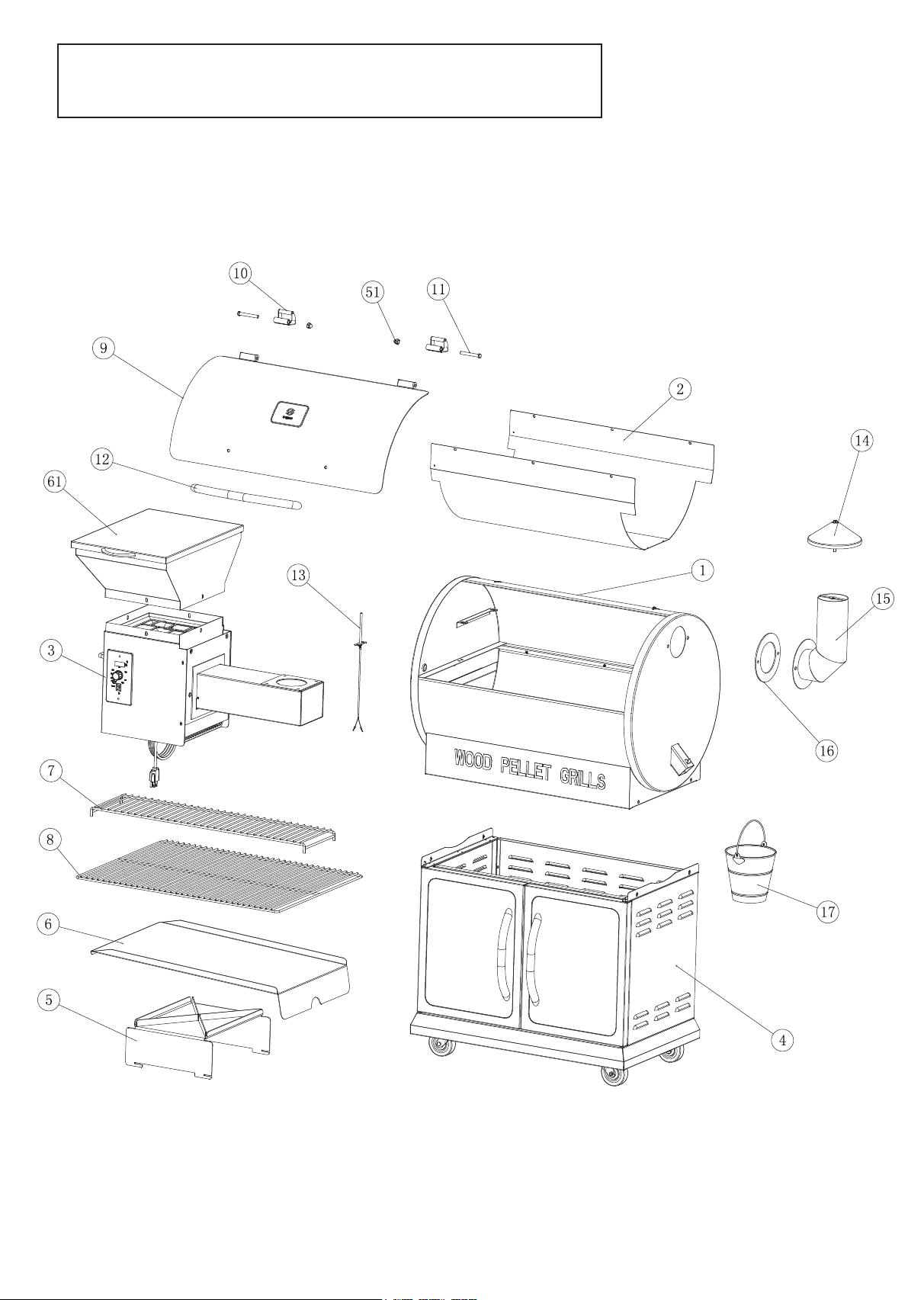
COMPONENT LIST
ITEM
QTY
DESCRIPTION
ITEM
QTY
DESCRIPTION
1
1
Grill Chamber Assembly
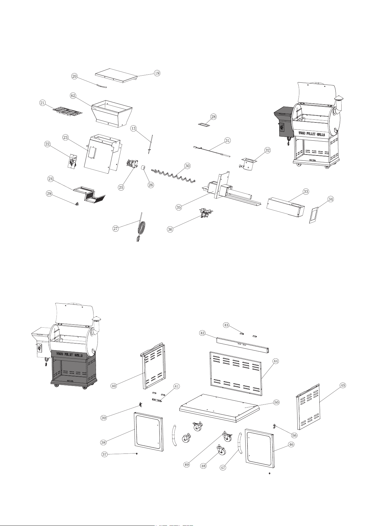
31 1 Hot Rod (Ignitor)
2 1 Thermal Baffle
32 1 Firepot Assembly
3
1
Hopper Bottom Assembly
33 1 Burner Box Assembly
4 1 Body Frame
34
1
Hopper Burner Gasket
5 1 Heat Baffle
35
1
Hopper Burner Assembly
6 1 Grease Drain Pan
36
1
Fan
7 1 Warming Rack
37 2 Bottom Pivot
8 1 Porcelain Grills
38 1 Left Door
9
1
Lid
39 1 Left Door Upper Pivot
10 2 Hinge Assembly
40 1 Left Plate
11 2 Hinge Pin
41 1 Magnet Block
12 1 Lid Handle
42
1
Beam
13
1
RTD Temperature Probe
43 4 Magnet
14
1
Chimney Cap Assembly
44 1 Back Board
15
1
Smoke Stack Assembly
45 1 Right Plate
16 1 Smoke Stack Gasket
46 1 Right Door
17 1 Grease Bucket
47 2 Door Handle
18 1 Screwdriver
48
2
Wheels (without brake)
19 1 Hopper Burner Lid
49 2 Wheels (with brake)
20 1 Hopper Lid Handle
50 1 Platform
21 1 Hopper Guard
51 2 Cap Nuts
22 1 Digital Control
52
19
Bolt
23
1
Hopper Bottom Assembly
53 8 Hexagon Bolt
24 1 Hopper Bottom Cover
54 8 Gasket
25 1 Auger Drive Motor
55 2 Hexagon Nut
26 1 Auger Tube Bushing
56 1 Right Door Pivot
27 1 Power Cord
57 2 Gasket
28 1 Thick Gasket
58
2
Bolt
29 1 Power Cord Collector
59 2
Wrench
30
1
Auger
9
60
63 Kep Nuts
Remark: 52*(Screw package) has 19 screws in total, including 18 necessary screw and 1
spare screw.
2
2
4
Bolt
ASSEMBLY INSTRUCTIONS
PARTS DIAGRAM
5
Hopper / Burner Assembly
Body Frame Assembly
6
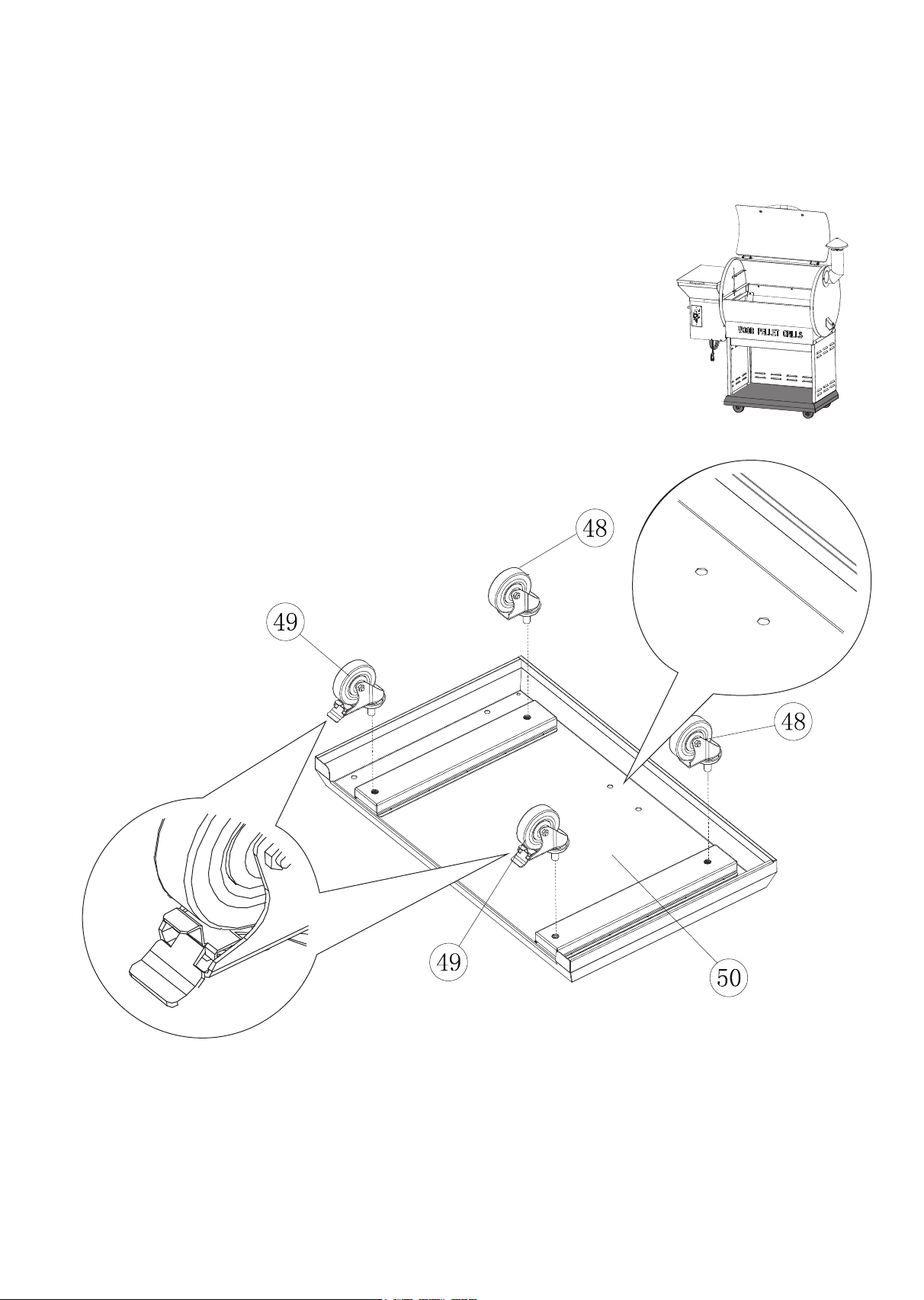
I. Assembling of Bottom Base
1. Turn the Platform (50) upside down so the lip is facing upward.
2. Insert the wheels (without brake) (48) in the screw holes. Tighten with wrench.
Note: These wheels should be installed on the side with a lip.
3. Insert the wheel (with brake) (49) into the screw holes. Tighten with wrench.
Note: These wheels should be installed on the side without a lip.
7
 Loading...