

Page 1
GENERAL DATA
Life Expectancy Minimum operations
Mechanical 1 x 10
8
Electrical 1 x 10⁵at 0.5 A, 125 VAC, Res.
1 x 10⁵at 2.0 A, 30 VDC, Res.
Operate Time 1 ms at nominal coil voltage
(typical)
Release Time (typical) 1 ms at nominal coil voltage
(with no coil suppression)
Bounce (typical) At 10 mA contact current
1 ms at operate or release
Capacitance < 2 pF at 10 KHz - coil to contacts
< 1 pF at 10 KHz - between open contacts
< 2 pF at 10 KHz - between contact sets
Dielectric Strength See table
(at sea level)
Dropout Greater than 10% of nominal coil voltage
Insulation Resistance 109ohms min. at 25°C, 500 VDC,
50% RH
Ambient Temperature At nominal coil voltage
Operating -40°C (-40°F) to 85°C (185°F)
Storage -40°C (-40°F) to 105°C (221°F)
Vibration Operational, 20 g, 10–1,000 Hz
Shock Operational, 50 g min., 11 ms
Non-destructive, 500 g min., 0.5 ms
Enclosure P.B.T. polyester, UL 94 V-0
Terminals Tinned copper alloy, P.C.
Max. Solder Temp. 260°C (500°F)
Max. Solder Time 10 seconds
Weight 0.8 grams
Packing unit in pcs 50 per plastic tube, 1000 per carton box
1000 per reel, 1000 or 5000 per carton box
ZETTLER electronics GmbH
Fax +49 89 800 97 200 www.ZETTLERelectronics.com
office@ZETTLERelectronics.com 0 97 800 89 +49 Tel.
Germany Puchheim, D-82178 Junkersstrasse 3,
2005-03-11
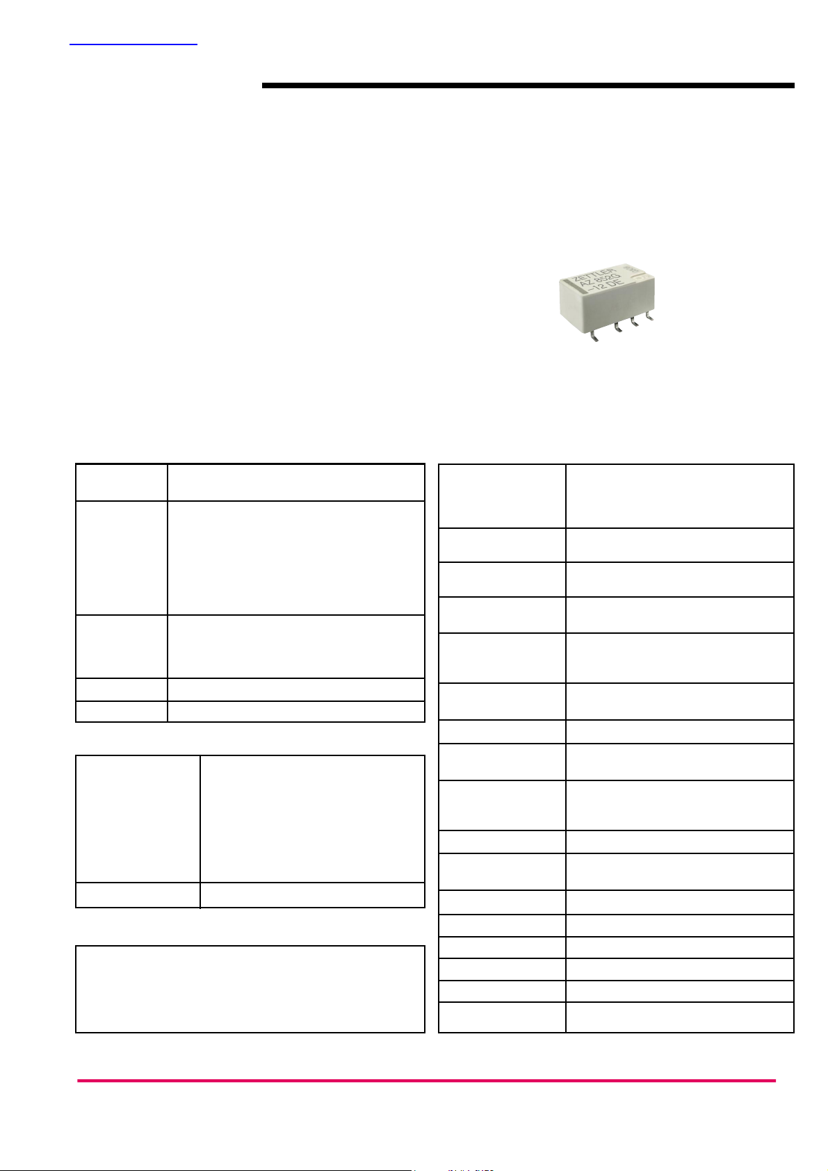
AZ852
MICROMINIATURE
POLARIZED RELAY
FEATURES
• Conforms to IEC60950/UL60950/EN60950
spacing and high breakdown voltage
Supplementary insulation
mains voltage 250 Vrms (SMT); 200 Vrms (THT)
Pollution Degree 2 (external); 1 (internal)
• Monostable and bistable (latching) coil versions available
• High dielectric and surge voltage:
2.5 KV surge (per Bellcore TA–NWT–001089)
2.5 KV surge (per FCC Part 68)
1,000 Vrms, open contacts
• Stable contact resistance for low level signal switching
• Epoxy sealed
• UL, CUR pending
CONTACTS
Arrangement DPDT (2 Form C)
Bifurcated crossbar contacts
Ratings Resistive load:
Max. switched power: 60 W or 62.5 VA
Max. switched current: 2.0 A
Max. switched voltage:220 VDC* or 250 VAC
* Note: If switching voltage is greater than 30 VDC,
special precautions must be taken.
Please contact the factory.
Rated Load
UL/CUR 0.5 A at125 VAC
2.0 A at 30 VDC
0.24 A at220 VDC
Material Palladium Ruthenium; gold clad
Resistance < 50 milliohms initially at 20 mV, 10 mA
COIL (Polarized)
Power
At Pickup Voltage 79 mW (3–12 VDC)
(typical) 98 mW (24 VDC)
Max. Continuous 0.73 W at 20°C (68°F)
Dissipation
Temperature Rise At nominal coil voltage
21°C (38°F) (3–12 VDC)
30°C (54°F) (24 VDC)
Temperature Max. 115°C (239°F)
NOTES
1. All values at 20°C (68°F).
2. Relay may pull in with less than “Must Operate” value.
3. Relay has fixed coil polarity.
4. Specifications subject to change without notice.
5. Ultrasonic cleaning is not recommended.
EU
查询AZ852供应商
Page 2
RELAY ORDERING DATA
NON-LATCHING VERSION
Nominal Coil Must Operate Max. Continuous Coil Resistance
ORDER NUMBER
VDC VDC VDC Ohm ± 10% THT Gull Wing* J-Leg*
1.5 1.13 3.4 16 AZ852N–1.5DE AZ852G–1.5DE AZ852J–1.5DE
3 2.10 6.8 64 AZ852N–3DE AZ852G–3DE AZ852J–3DE
4.5 3.15 10.3 145 AZ852N–4.5DE AZ852G–4.5DE AZ852J–4.5DE
5 3.50 11.4 178 AZ852N–5DE AZ852G–5DE AZ852J–5DE
6 4.20 13.7 257 AZ852N–6DE AZ852G–6DE AZ852J–6DE
9 6.30 20.4 574 AZ852N–9DE AZ852G–9DE AZ852J–9DE
12 8.40 27.3 1,028 AZ852N–12DE AZ852G–12DE AZ852J–12DE
24 16.80 45.6 2,880 AZ852N–24DE AZ852G–24DE AZ852J–24DE
LATCHING VERSION
Nominal Coil Must Operate Max. Continuous Coil Resistance ORDER NUMBER
VDC VDC VDC Ohm ± 10% THT Gull Wing* J-Leg*
1.5 1.13 4.1 23 AZ852PN–1.5DE AZ852PG–1.5DE AZ852PJ–1.5DE
3 2.25 8.1 90 AZ852PN–3DE AZ852PG–3DE AZ852PJ–3DE
4.5 3.38 12.1 203 AZ852PN–4.5DE AZ852PG–4.5DE AZ852PJ–4.5DE
5 3.75 13.5 250 AZ852PN–5DE AZ852PG–5DE AZ852PJ–5DE
6 4.50 16.2 360 AZ852PN–6DE AZ852PG–6DE AZ852PJ–6DE
9 6.75 24.2 810 AZ852PN–9DE AZ852PG–9DE AZ852PJ–9DE
12 9.00 32.3 1,440 AZ852PN–12DE AZ852PG–12DE AZ852PJ–12DE
24 18.00 41.9 2,880 AZ852PN–24DE AZ852PG–24DE AZ852PJ–24DE
* Available only in Tape and Reel available (1K pcs/reel minimum)
ZETTLER electronics GmbH
Fax +49 89 800 97 200 www.ZETTLERelectronics.com
office@ZETTLERelectronics.com 0 97 800 89 +49 Tel.
Germany Puchheim, D-82178 Junkersstrasse 3,
2005-03-11
AZ852
INITIAL DIELECTRIC STRENGTH (minimum) SURGE
VRMS, 1 min. Peak (V) Rise Time (µs) DecayTime* (µs)(1/2 peak)
Between open contacts 1,000 1,500 2 (10) 10 (160)
Between contact sets 1,000 1,500 2 (10) 10 (160)
Between coil and contacts 1,800 2,500 2 (10) 10 (160)
* Decay time measured from beginning of surge.
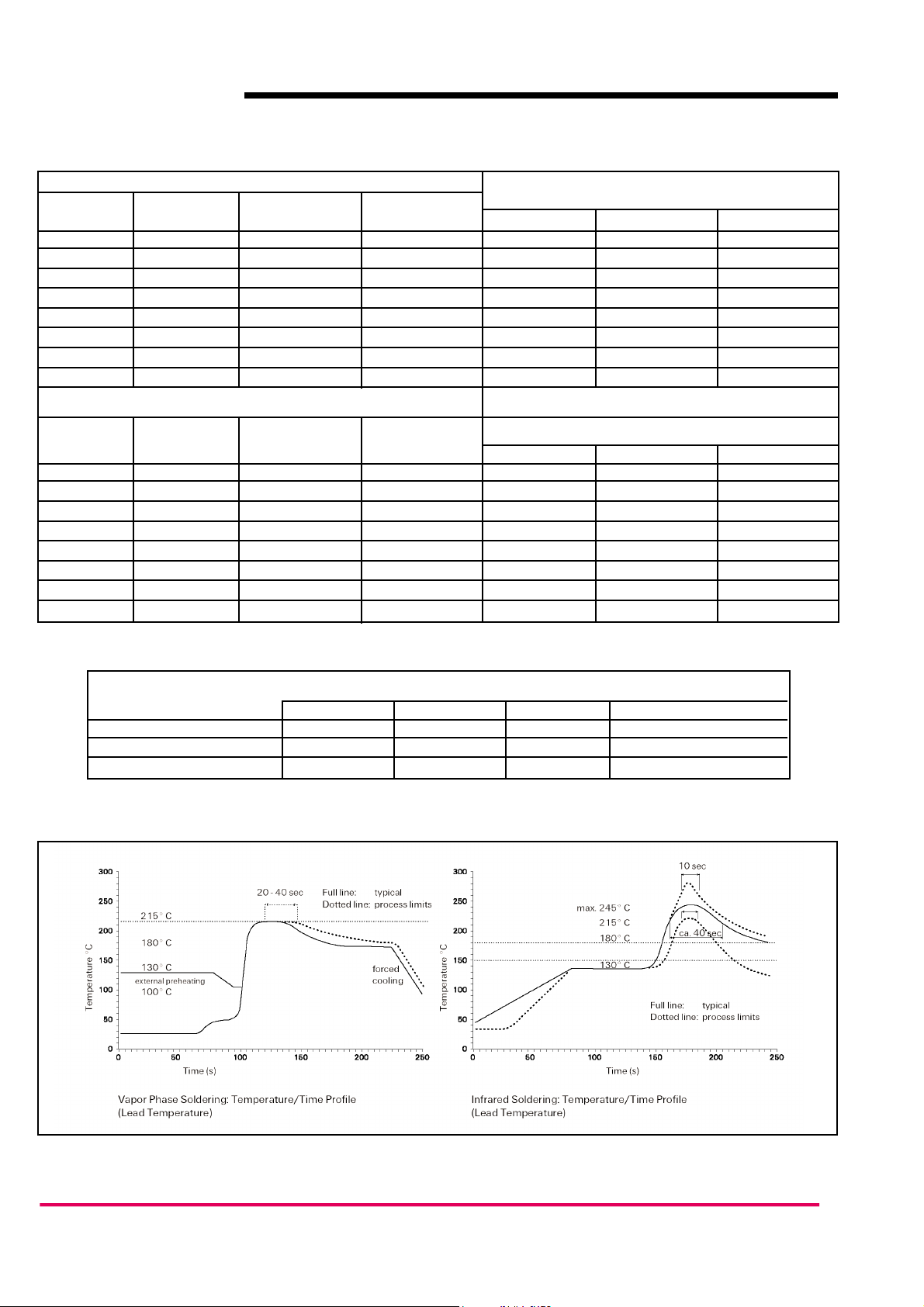
Temperature Profile
EU
Recommended Soldering Profile according CECC 00802
Page 3

MECHANICAL DATA
AZ852
ZETTLER electronics GmbH
Fax +49 89 800 97 200 www.ZETTLERelectronics.com
office@ZETTLERelectronics.com 0 97 800 89 +49 Tel.
Germany Puchheim, D-82178 Junkersstrasse 3,
2005-03-11
EU
DIMENSIONS
NARROW GULL WINGS J-LEGS
mm inch mm inch mm inch
L 10 ±0.08 0.393 ±0.003 10 ±0.08 0.393 ±0.003 10 ±0.08 0.393 ±0.003
W 5.7 ±0.3 0.224 ±0.012 6 ±0.08 0.236 ±0.003 6 ±0.08 0.236 ±0.003
H 5.85 -0.15 0.230 -0.006 5.65 -0.2 0.222 -0.008 5.65 -0.2 0.222 -0.008
T 3.2 0.125 N/A N/A N/A N/A
T1 N/A N/A 7.5 ±0.3 0.295 ±0.011 2.8 ±0.2 0.110 ±0.007
T2 3.2 ±0.1 0.126 ±0.006 5.08 ±0.1 0.200 ±0.004 5.08 ±0.1 0.200 ±0.004
D1 3.2 ±0.15 0.126 ±0.006 3.2 ±0.15 0.126 ±0.006 3.2 ±0.15 0.126 ±0.006
D2 2.2 ±0.15 0.087 ±0.006 2.2 ±0.15 0.087 ±0.006 2.2 ±0.15 0.087 ±0.006
Tw 0.4 0.015 0.4 0.015 0.4 0.015
S 0.3 ±0.05 0.011 ±0.002 N/A N/A N/A N/A
Narrow Version
Gull Wings
J Legs
J Legs
Gull Wings
Narrow Version
Non-latching type
not energized condition
Latching type, 1 coil
RESET condition
ø min 0.75
PC BOARD LAYOUT
WIRING DIAGRAM
VIEWED TOWARD TERMINALS
TOP VIEW
TOP VIEW
Page 4

AZ852
ZETTLER electronics GmbH
Fax +49 89 800 97 200 www.ZETTLERelectronics.com
office@ZETTLERelectronics.com 0 97 800 89 +49 Tel.
Germany Puchheim, D-82178 Junkersstrasse 3,
2005-03-11
EU
Packaging Specifications
Tube for THT version - 50 relays per tube, 1000 relays per box
Reel dimension
Tape and reel for SMT version - 1000 relays per reel, 1000 or 5000 relays per box
 Loading...