


CONTACTS
Arrangement SPST (1 Form A, or B)
SPDT (1 Form C)
Ratings Resistive load:
Max. switched power: 560 W or 8310 VA
Max. switched current: 30 A (Form A)
15 A (Form B)
Max. switched voltage: 277 VAC, 28 VDC
UL, CUR 1 Form A
30 A at 277 VAC, General Use [1] [2]
2 Hp at 250 VAC [1] [2]
1 HP at 125 VAC [1] [2]
30 A at 28 VDC [1]
20/60 A (FLA/LRA) at 277 VAC 30k cycles [1]
1 Form B
15 A at 277 VAC, General Use [1]
10 A at 28 VDC [1]
0.5 HP at 250 VAC [1]
.25 HP at 125 VAC [1]
10/33 (FLA/LRA) at 277 VAC 30k cycles [1]
1 Form C
30/20 A (N.O./N.C.) at 277 VAC, General Use [1] [2]
20/10 A (N.O./N.C.) at 28 VDC [1]
2/0.5 HP (N.O./N.C.) at 250 VAC [1] [2]
1/.25 HP (N.O./N.C.) at 125 VAC [1] [2]
20/60 (FLA/LRA) at 277 VAC 30k cycles, N.O. [1]
10/33 (FLA/LRA) at 277 VAC 30k cycles, N.C [1]
Material Silver cadmium oxide [1] or silver tin oxide [2]
Resistance < 50 milliohms initially
(24 V, 1 A voltage drop method)
GENERAL DATA
Life Expectancy Minimum operations
Mechanical 1 x 10
7
Electrical 1 x 10⁵at 30 A 120 VAC Res.
Operate Time 15 msec max. at nominal coil voltage
Release Time 10 msec max. at nominal coil voltage
(without suppression)
Dielectric Strength 1500 Vrms contact to contact
(at sea level for 1 min.) 2500 Vrms contact to coil
4000 Vrms contact to coil “T” version
Insulation Resistance 1000 megohms min. at 20°C, 500 VDC
50% RH
Dropout DC:> 10%of nominal coilvoltage
AC: > 20% of nominal coil voltage
Ambient Temperature
Operating -40°C (-40°F) to 85°C (185°F) - DC coils
-40°C (-40°F) to 70°C (158°F) - AC coils
Storage -40°C (-40°F) to 105°C (221°F)
Vibration 0.062" (1.5 mm) DA at 10–55 Hz
Shock 10 g
Enclosure P.B.T. polyester
Terminals Tinned copper alloy, P.C.,
Max. Solder Temp. 270°C (518°F)
Max. Solder Time 5 seconds
Max. Solvent Temp. 80°C (176°F)
Max. Immersion Time 30 seconds
Weight 36 grams
Packing unit in pcs 40 per plastic tray / 280 per carton box
AZ2250
ZETTLER electronics GmbH
Fax +49 89 800 97 200 www.ZETTLERelectronics.com
office@ZETTLERelectronics.com 0 97 800 89 +49 Tel.
Germany Puchheim, D-82178 Junkersstrasse 3,
2004-12-22
30 AMP MINIATURE
POWER RELAY
FEATURES
• 1 Form A, B and C contacts available
• AC and DC coils available
• High dielectric strength version available
• Epoxy sealed versions available
• UL Class F (155°C) standard
• UL, CUR file E44211
COIL
Power
At Pickup Voltage 500 mW (DC coil)
(typical) 1.4 VA (AC coil)
Max. Continuous 1.7 W at 20°C (68°F) ambient
Dissipation 2.7 VA at 20°C (68°F) ambient
Temperature Rise 43°C (77°F) at nominal coil voltage
Max. Temperature 155°C (311°F)
NOTES
1. All values at 20°C (68°F).
2. Relay may pull in with less than “Must Operate” value.
3. Specifications subject to change without notice.
查询AZ2250-1A-277AF供应商
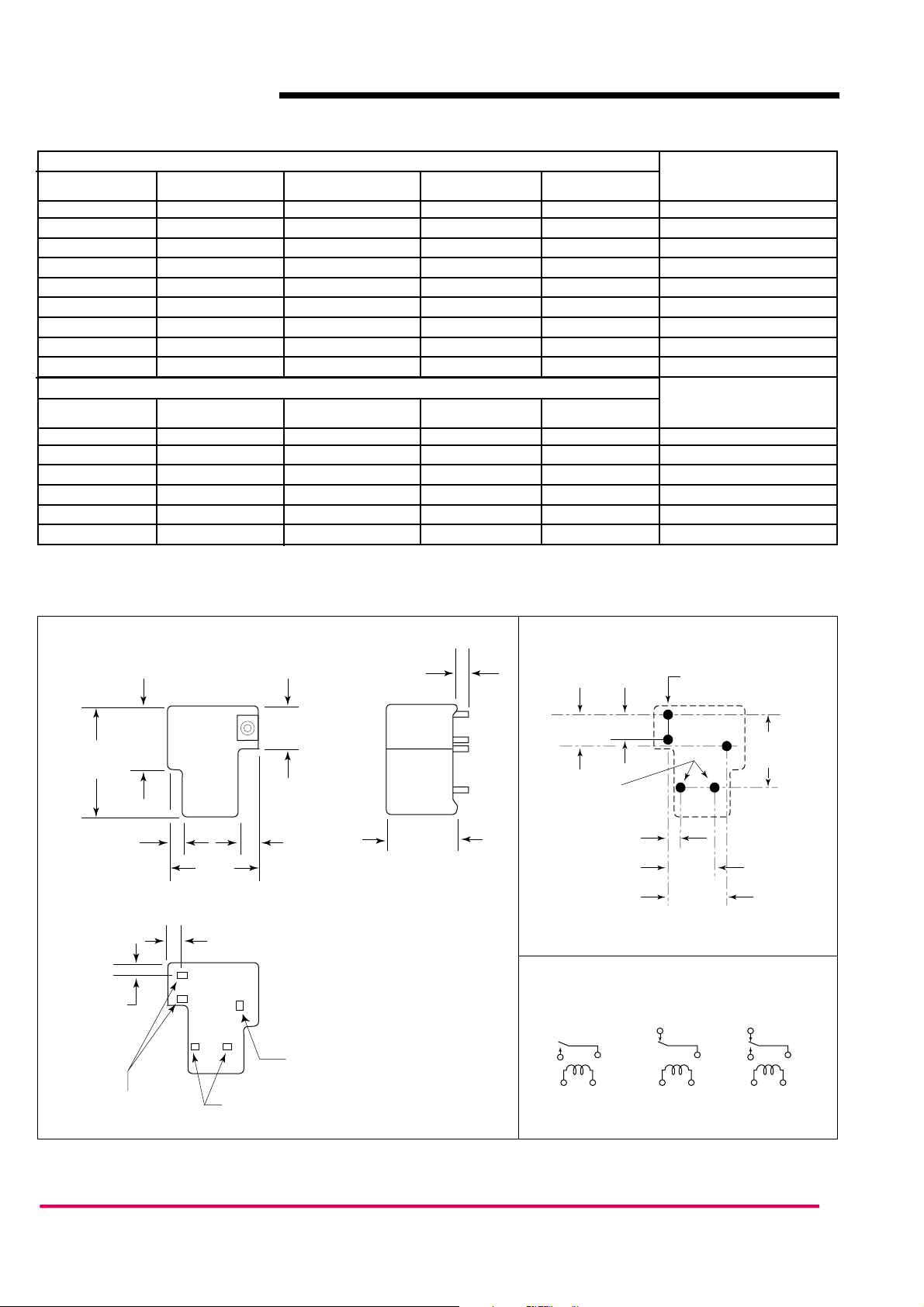
Dimensions in inches with metric equivalents in parentheses. Tolerance: ± .010"
RELAY ORDERING DATA
COIL SPECIFICATIONS – DC Coil
Nominal Coil Must Operate Max. Continuous Nominal Current Coil Resistance
ORDER NUMBER*
VDC VDC VDC mA ± 10% Ohm ± 10%
5 3.75 6.4 185 27 AZ2250–1A–5DF
6 4.50 7.8 150 40 AZ2250–1A–6DF
9 6.75 12.2 93 97 AZ2250–1A–9DF
12 9.0 15.4 77 155 AZ2250–1A–12DF
15 11.3 19.8 59 256 AZ2250–1A–15DF
18 13.5 24.1 47 380 AZ2250–1A–18DF
24 18.0 32.0 36 660 AZ2250–1A–24DF
48 36.0 62.6 19 2,560 AZ2250–1A–48DF
110 82.5 163.2 8 13,450 AZ2250–1A–110DF
COIL SPECIFICATIONS – AC Coil 50/60 Hz
Nominal Coil Must Operate Max. Continuous Nominal Coil Coil Resistance ORDER NUMBER*
VAC VAC VAC Power VA Ohm ± 10%
12 9.6 13.8 2.3 25 AZ2250–1A–12AF
24 19.2 27.6 2.1 100 AZ2250–1A–24AF
120 96.0 138.0 2.3 2,500 AZ2250–1A–120AF
208 166.4 239.2 2.2 11,000 AZ2250–1A–208AF
220/240 176.0 276.0 2.2/2.6 13,490 AZ2250–1A–240AF
277 221.6 318.5 2.2 15,000 AZ2250–1A–277AF
* Substitute “1B” or “1C” in place of “1A” for 1 Form B or 1 Form C. Add suffix “E” to “1A” or “1B” or “1C” for silver tin oxide contacts.
Substitute “DEF” or “AEF” in place of “DF” or “AF” for epoxy sealed version. Substitute “TF” in place of “F” for 4000 Vrms dielectric strength version.
AZ2250
ZETTLER electronics GmbH
Fax +49 89 800 97 200 www.ZETTLERelectronics.com
office@ZETTLERelectronics.com 0 97 800 89 +49 Tel.
Germany Puchheim, D-82178 Junkersstrasse 3,
2004-12-22
MECHANICAL DATA
.693
(17.6)
1.268
(32.2)
.094
(2.4)
.098
(2.5)
1.063
(27.0)
.197
(5.0)
.504
(12.8)
.181
(4.6)
.045 x .045
(1.14 x 1.14)
.130
(3.3)
(20.1)
.791
PC BOARD LAYOUT
.400
(10.16)
2 x ø .043
.300
(7.62)
[ø 1.1]
.150
(3.8)
.550
(14.0)
Viewed toward terminals
3 x ø .083
[ø 2.1]
.700
(17.8)
.900
(22.86)
WIRING DIAGRAMS
Form A Form B Form C
.032 x .062
(0.81 x 1.57)
.025 x .025
(0.63 x 0.63)
Viewed toward terminals
 Loading...