


UTILIX HT
OPERATOR´S MANUAL
2/2019
45
Tractor is Zetor. Since 1946.
55

1
ZETOR
This Operator’s Manual for the Zetor tractors, which we are presenting to you will help you to
become familiar with the operation and maintenance of your new tractor.
Although many of you have rich experience with the operation of other tractors, please, read the
information contained in this Operator’s Manual very carefully.
In the Manual you will find a lot of new information and get a perfect overview of how to use the
tractor with maximum efficiency during various kinds of work.
If you observe the rules of tractor operation and maintenance and driving safety, your new tractor will
become your reliable and long-term friend.
The manufacturer of the tractor wishes you thousands of hours of satisfactory work.
ZETOR
The technical specifications and information about the design, equipment, material and app earance are valid at the time
of print. The manufacturer reserves the right to implement changes.
The instructions for use are a part of the machine.
Brno

2

Tractor identification ........................................................................................................................................ 9
CONTENTS
3
Warranty of the product ................................................................................................................................. 9
Parts .............................................................................................................................................................. 9
About this manual .......................................................................................................................................... 11
Introduction & Description ............................................................................................................................ 13
Tractor an introduction ................................................................................................................................. 13
Description ................................................................................................................................................... 14
ROPS (Roll over protection structures) ....................................................................................................... 15
Roll over protective structures (ROPS) ....................................................................................................... 15
Danger ......................................................................................................................................................... 15
Use of the tractor with the ROPS lowered can cause fatal injuries ............................................................. 15
Damage of the ROPS .................................................................................................................................. 15
How to adjust the Seat ................................................................................................................................ 16
For sliding seat ............................................................................................................................................ 16
Seat suspension adjustment knob .............................................................................................................. 17
Cushion strength adjustment ....................................................................................................................... 17
Safety instructions, Do's & Don'ts ................................................................................................................ 19
Introduction to safety information ................................................................................................................ 19
Signal words ................................................................................................................................................ 19
Introduction to safety instructions Introduction to safety instructions .......................................................... 19
Protection children ....................................................................................................................................... 19
Use of rops and seat belt ............................................................................................................................ 20
Precaution to avoid tipping .......................................................................................................................... 20
Safe parking of the tractor ........................................................................................................................... 20
Keep riders off tractor .................................................................................................................................. 20
Handle fuel safely-avoid fires ...................................................................................................................... 21
Stay clear of rotating shafts ......................................................................................................................... 21
Always use safety lights and devices .......................................................................................................... 21
Practice safe maintenance .......................................................................................................................... 22
Avoid high-pressure fluids ........................................................................................................................... 22
Prevent battery explosions .......................................................................................................................... 22
Prevent acid burns ....................................................................................................................................... 23
Service tractor safely ................................................................................................................................... 23
Work in ventilated area ................................................................................................................................ 24
Tractor runaway
Safety starter switch .................................................................................................................................... 24
Emergency exits .......................................................................................................................................... 24
Safety precautions
Towing safely ............................................................................................................................................... 27
Falling object protective structure (FOPS) .................................................................................................. 27
Operator protective structure (OPS) ............................................................................................................ 27
Use of hazardous substances ..................................................................................................................... 28
Safety tips during maintenance ................................................................................................................... 30
Mounting and demounting implements ....................................................................................................... 31
The following precautions are suggested to help prevent accidents .......................................................... 32
Do's-for better performance ......................................................................................................................... 35
Don'ts - for safe operation .......................................................................................................................... 36
Safety signs ..................................................................................................................................................... 37
General safety information .......................................................................................................................... 37
Decals on the dash cover ............................................................................................................................ 37
Decals on the chassis .................................................................................................................................. 38
Decals on the cabin ..................................................................................................................................... 39
Universal symbols .......................................................................................................................................... 41
Controls, Instruments & Operations ............................................................................................................. 43
Description of tractor controls ...................................................................................................................... 43
Battery disconnector .................................................................................................................................... 43
Instrument and switches .............................................................................................................................. 44
Main switch (key switch) .............................................................................................................................. 45
Headlights, turn signal lights, beacon and horn switch ............................................................................... 45
Tachometer.................................................................................................................................................. 46
Hour meter ................................................................................................................................................... 46
Fuel gauge and water temperature gauge ................................................................................................. 46
Hazard warning signal switch ...................................................................................................................... 46
........................................................................................................................................... 24
when using the loader .................................................................................................. 25

Warning lights ............................................................................................................................................. 47
CONTENTS
4
Independent PTO ........................................................................................................................................ 48
PTO shaft revolutions 540 and 1000 rpm shifting lever .............................................................................. 50
Connecting and disconnecting implement ................................................................................................... 51
Cruise control button ................................................................................................................................... 52
Cruise speed control switch ......................................................................................................................... 52
Load sensing button .................................................................................................................................... 52
Mode (sensitivity) switch .............................................................................................................................. 53
Tractor controls ............................................................................................................................................ 54
Hand throttle (Throttle lever)........................................................................................................................ 55
Speed and direction control pedals ............................................................................................................. 55
Foot brakes .................................................................................................................................................. 56
Parking brake lever ...................................................................................................................................... 57
To avoid personal unjury: ............................................................................................................................ 57
Air brakes of trailers and semi-trailers ......................................................................................................... 57
Air pressure indication ................................................................................................................................. 57
The button for temporary deactivation of brakes of the trailer or semi-trailer ............................................. 58
One-hose and two-hose brakes .................................................................................................................. 59
One-hose brakes ......................................................................................................................................... 59
Two-hose brakes ......................................................................................................................................... 59
Sub gear lever (Linear shift lever) ............................................................................................................... 60
Diff-lock pedal .............................................................................................................................................. 60
Front axle drive lever ................................................................................................................................... 61
Driver's seat ................................................................................................................................................. 61
Tilt lever ....................................................................................................................................................... 62
Operating the hydraulics .............................................................................................................................. 63
Position control ............................................................................................................................................ 63
Lowering speed control knob for the 3 point hitch ....................................................................................... 64
Outer hydraulic circuit .................................................................................................................................. 64
Outer hydraulic circuit controls .................................................................................................................... 65
Remote hydraulic control valve coupler connecting and disconnecting ...................................................... 65
Connection................................................................................................................................................... 65
Disconnection .............................................................................................................................................. 65
Joystick lever ............................................................................................................................................... 66
Safety implement for joystick lever .............................................................................................................. 66
Rear three-point hitc
Adjustment of the top link ............................................................................................................................ 68
Adjustment of the lift link on the lower link
Mounting implement .................................................................................................................................... 69
*Front three-point hitch ................................................................................................................................ 70
Controlling front three-point hitch ................................................................................................................ 70
Hydraulic lock of the front three-point hitch ................................................................................................. 71
Working and transport position of the front three-point hitch ...................................................................... 72
Driving with agricultural machines attached to the front three-point hitch ................................................... 72
Towing equipment ....................................................................................................................................... 72
Maximum permissible load of the hitch ....................................................................................................... 72
Lower hitch ................................................................................................................... ............................... 73
Connection and disconnection of implements ............................................................................................. 73
Multistage adjustable suspension ............................................................................................................... 73
Disassembly of the rear PTO cover ............................................................................................................ 73
Lower hitch disassembly ............................................................................................................................. 74
Height adjustment and disassembly of the multi-level hitch attachment tail piece ..................................... 74
Starting the engine ...................................................................................................................................... 75
Stopping the engine ..................................................................................................................................... 75
Warming up ................................................................................................................................................. 75
Warming up in cold weather ........................................................................................................................ 75
Running-in Period ........................................................................................................................................ 75
Sharp change of direction in the field .......................................................................................................... 76
Normal service braking and parking ............................................................................................................ 76
Driving downhill ........................................................................................................................................... 77
Operation of the diff lock .............................................................................................................................. 77
Check during driving .................................................................................................................................... 78
Oil pressure light .......................................................................................................................................... 78
h .................................................................................................................................. 67
.................................................................................................. 69

Battery charging .......................................................................................................................................... 78
CONTENTS
5
Fuel gauge ................................................................................................................................................... 78
Engine cooling water ................................................................................................................................... 79
Trailer socket (seven terminal electrical socket type) ................................................................................. 79
Treads .......................................................................................................................................................... 80
Changing the front wheel tread ................................................................................................................... 81
Changing the rear wheel tread .................................................................................................................... 81
Front drive axle fenders ............................................................................................................................... 81
Setting wheel stops with front drive axle ..................................................................................................... 82
Front loader mounting points ....................................................................................................................... 83
Main technical parameters ............................................................................................................................ 85
Check and service ....................................................................................................................................... 85
Service inspections ...................................................................................................................................... 85
Pre-start checks ........................................................................................................................................... 85
Engine coolant ............................................................................................................................................. 85
Engine oil ..................................................................................................................................................... 86
Transmission oil ........................................................................................................................................... 87
Fuel .............................................................................................................................................................. 87
Tyre pressure .............................................................................................................................................. 88
Tire size and inflation pressure.................................................................................................................... 88
Tire inflation ................................................................................................................................................. 88
Steering ....................................................................................................................................................... 89
Brake ........................................................................................................................................................... 89
Electrical installation .................................................................................................................................... 89
Installation of the front loader ...................................................................................................................... 89
Maintenance and adjustment schedule ....................................................................................................... 90
Periodical check and service table .............................................................................................................. 90
Diagram of filling points and lubrication points ............................................................................................ 93
Fuels, coolants and lubricants used - amounts ........................................................................................... 94
Recommended SAE viscosity grades for engine oil ................................................................................... 94
ZETOR service fillings ................................................................................................................................. 94
Motor oils ..................................................................................................................................................... 94
Oil in the gearbox and final drivehousing .................................................................................................... 94
Oil for the front driving axle .......................................................................................................................... 94
Other recommended service fillings tested on Zetor tractors ...................................................................... 94
Oil to gear systems of tractors ..................................................................................................................... 94
Fuel .............................................................................................................................................................. 94
Procedure to open the front hood
Front bonnet opening .................................................................................................................................. 95
Opening the side cover ................................................................................................................................ 95
Fuel sys
Bleeding the fuel system ............................................................................................................................. 96
Changing oil in tractor .................................................................................................................................. 97
Changing engine oil ..................................................................................................................................... 97
Draining oil from engine ............................................................................................................................... 98
Engine oil filter ............................................................................................................................................. 98
Pouring oil to engine .................................................................................................................................... 98
Changing the transmission oil ..................................................................................................................... 99
Changing front axle oil ............................................................................................................................... 100
Cleaning and replacing filters .................................................................................................................... 101
Engine oil filter ........................................................................................................................................... 101
Fuel filter .................................................................................................................................................... 102
Hydraulic oil filter ....................................................................................................................................... 102
Changing coolant ....................................................................................................................................... 103
Anti freeze.................................................................................................................................................. 103
Cleaning the radiator ................................................................................................................................. 104
Greasing the tractor ................................................................................................................................... 105
Setting the play of controls ........................................................................................................................ 106
Adjusting the brake .................................................................................................................................... 106
Adjusting method ....................................................................................................................................... 106
Adjusting the throttle lever ......................................................................................................................... 106
Adjusting toe-in .......................................................................................................................................... 106
Checking the battery .................................................................................................................................. 107
tem ................................................................................................................................................. 96
................................................................................................................ 95

Battery maintenance .................................................................................................................................. 107
CONTENTS
6
Battery charging ........................................................................................................................................ 108
Battery disconnect ..................................................................................................................................... 108
Battery disconnector .................................................................................................................................. 108
Fan belt adjustment ................................................................................................................................... 109
Alternator inspect ....................................................................................................................................... 109
Alternator and fan belts inspect/adjust/replace ......................................................................................... 109
Air conditioner compressor belt adjustment .............................................................................................. 110
Air filter maintenance ................................................................................................................................. 110
Checking hoses and lines .......................................................................................................................... 111
Checking the wiring harness and fuses ..................................................................................................... 111
Replacing fuses ......................................................................................................................................... 112
Main fuses .................................................................................................................... ............................. 112
Storage ...................................................................................................................................................... 113
For daily or short term storage ............................................................................................... ................... 113
Long-term storage ..................................................................................................................................... 113
Re-use after long term storage .................................................................................................................. 113
Fuel saving tips .......................................................................................................................................... 113
Air cleaning system ................................................................................................................................... 113
Engine ........................................................................................................................................................ 114
Fuel system ............................................................................................................................................... 114
Oil system .................................................................................................................................................. 114
Cooling system .......................................................................................................................................... 114
How to use of jacks ................................................................................................................................... 115
Cabin .............................................................................................................................................................. 117
Instruments and related parts .................................................................................................................... 117
Doors ......................................................................................................................................................... 118
Rear window .............................................................................................................................................. 118
Side window .............................................................................................................................................. 118
Work light
Rearview mirrors ....................................................................................................................................... 119
Cab ceiling ................................................................................................................................................. 119
How to c
Interior devices .......................................................................................................................................... 120
Ventilation .................................................................................................................................................. 120
Re-circulation inlets fully closed ................................................................................................................ 120
Control panel on right cab pillar ................................................................................................................. 121
Windscreen washer tank ........................................................................................................................... 121
Interior lamp ............................................................................................................................................... 122
Blower control switch ................................................................................................................................. 122
Temperature control .................................................................................................................................. 122
Air conditioner switch ................................................................................................................................. 122
Circulation diffuser ..................................................................................................................................... 123
Heating system .......................................................................................................................................... 123
Heating system configuration .................................................................................................................... 123
Compressor belt adjustment ...................................................................................................................... 124
Air conditioning system .............................................................................................................................. 124
Roof hatch (if equipped) ............................................................................................................................ 124
Cab air intake filter ..................................................................................................................................... 125
Radio, CD player (if equipped) .................................................................................................................. 125
Ash tray ...................................................................................................................................................... 126
Cigarette lighter ......................................................................................................................................... 126
Main technical parameters .......................................................................................................................... 129
Maximum permissible weight of the unit (tractor with trailer or semi-trailer) ............................................. 131
Maximum permissible tractor axle load ..................................................................................................... 131
Permitted maximum weight of set 'tractor + mounted machine' (kg) ........................................................ 131
Manoeuvrability condition .......................................................................................................................... 131
Permissible wheel combination for tractors and load capaci
Traveling speed ......................................................................................................................................... 132
Noise levels .................................................................................................................. ............................. 133
Vibration referred to the operator position ................................................................................................. 134
Fault tracing .................................................................................................................................................. 135
Engine troubleshooting .............................................................................................................................. 135
s (front and rear) ........................................................................................................................ 118
ontrols cabin ................................................................................................................................ 120
ty of tires ...................................................... 131

Brake and hydraulic system troubleshooting ............................................................................................. 137
CONTENTS
78
Steering wheel and electric instruments troubleshooting .......................................................................... 138
Towing the tractor ........................................................................................................................................ 139
Wiring Diagram ............................................................................................................................................. 141
UTILIX HT 45 / UTILIX HT 55 Electric system diagram (1) ....................................................................... 141
UTILIX HT 45 / UTILIX HT 55 Electric system diagram (2) ....................................................................... 142
UTILIX HT 45 / UTILIX HT 55 Cabin wiring diagram (1) ........................................................................... 143
UTILIX HT 45 / UTILIX HT 55 Cabin wiring diagram (2) ........................................................................... 144
UTILIX HT 45 / UTILIX HT 55 Cabin wiring diagram (3) ........................................................................... 145
Power train .................................................................................................................................................... 147
Index ............................................................................................................................................................... 149


The engine number is stamped on the left hand side of the engine block.
TRACTOR IDENTIFICATION
9
The chassis number is shown on the left hand side of the tractor as shown in the drawing.
1 - Stamped position of the Engine type or Number
2 - Stamped position of the chassis number
U18N001
Warranty of the product
The manufacturer warrants this product and full details of the warranty are provided on a separate warranty
schedule.
Parts
To obtain spare parts please contact your nearest dealer and give him the details listed below.
Tractor model
Tractor serial number
Tractor engine number
Part number and description
Quantity required

NOTES
10

This manual has been prepared to assist you in following / adopting the correct procedure for running-in
ABOUT THIS MANUAL
11
operation and maintenance of your new ZETOR Tractor.
Your tractor has been designed and built to provide maximum performance, low fuel consumption and ease
of use. To maintain the condition and ensure trouble-free performance, it is important that maintenance is
performed at the recommended intervals as described in this manual.
Read this Manual carefully and keep it in a convenient place for future reference.
If at any time you require advice concerning your Tractor, do not hesitate to contact your Authorized ZETOR
dealer / Distributor. He has trained personnel, genuine parts and necessary equipments to undertake all your
service requirements.
All data given in this book is subject to production variations. Dimensions & weight are approximate only and
the illustrations do not necessarily show Tractors in standard condition.
For exact information about any particular Tractor, please consult your ZETOR dealer / Distributor.

NOTES
12

Tractor an introductio
n
p
.
INTRODUCTION & DESCRIPTION
13
1 - Right turn (Clockwise)
2 - Right
3 - Front
4 - Left
5 - Rear
6 - Left turn (Counterclockwise)
U18N002
The word 'tractor' is derived from 'traction', which means towing.
A tractor is necessary for drawing or towing equipment, implements or carts that are suitably connected to
the tractor body.
The tractor can also be used as a driving machine, thanks to the Power Take-off or PTO shaft.
This manual provides instructions for the operation, maintenance and storage of all Zetor tractor models.
This material has been elaborated in detail to help you better understand maintenance and efficient
operation.
If you need information not provided in this manual or the services of a trained mechanic, please contact
Zetor Dealer/distributor at your location. Dealers and distributors are kept informed about the latest methods
of servicing tractors.
They are supplied with original spare parts and are fully supported by the manufacturer.
Through this manual
The use of the terms LEFT, RIGHT, FRONT and REAR must be understood, to avoid any confusion when
following the introductions. The LEFT and RIGHT means left and right sides of the Tractor when facing
forward in the driver's seat, Reference to the FRONT indicates the radiator end of the Tractor, while the
REAR, indicates the drawbar end (Fig. U18N002).
When spare parts are required, always specify the Tractor and engine serial number when ordering these
parts. (See Fig. U18N001).This will facilitate faster delivery and help ensure that the correct parts for your
particular Tractor is received. The tractor serial number is punched on a plate attached to the left hand side
of the engine body (See Fig. U18N001), For easy reference, we suggest you to write the number in the
ace provided in the owner's personal data
s

Descriptio
n
INTRODUCTION & DESCRIPTION
14
General construction
The transmission case, clutch, clutch housing, engine and front axle support are bolted together to form
a rigid unit.
Front Axle and wheels
The 4WD front axle is a center-pivot, reverse Eliot type. The front wheel drive mechanism is incorporated as
a part of the axle.
The front wheel drive power is taken off the rear transmission and transmitted to the differential in the front
axle where the power is divided into right and left and to the respective final cases.
In the final cases, the transmitted revolution is reduced by the level gears to drive the front wheel. The 4WD
mechanism with level gears provides wider steering and greater durability.
Engine
The tractors are fitted with fuel efficient engine with 4 cylinders manufactured by Perkins.
Hydrostatic transmission
The tractor is equipped with a three-speed hydrostatic transmission with power steering, individual speed
ranges are shifted using the selector lever. The tractor is equipped with two pedals, for speed and for
forward / reverse travel. The tractor with an independent PTO is equipped with an electro-hydraulic clutch.
Brakes
Tractors are equipped with independent disc brakes. The handbrake lever is adapted for parking.
Rear axle and wheels
This is mounted on ball bearings and is enclosed in removable housing which are bolted to the transmission
case. The rim & Disc fitted with rear tires are bolted to the outer flange of rear axle.
Hydraulic system & Linkages
ZETOR Tractors are fitted with Live independent, very touch of hydraulic System.
Three point Linkages can be used for Category 1 type of implements.
Steering
It consists of hydrostatic power steering system, which has a hydraulic cylinder and tandem type hydraulic
pump.
Electrical system
A 12 Volt lead acid propylene battery is used to activate the engine through the starter motor and the
electrical system comprising horn, head lamp. Side indicator lamps, plough lamp, brake light, gauge lamp,
hazard lamp. Generator or alternator, fuse box also from part of the electrical system.
Warning: When operating the tractor at High speed, Do not attempt to make sharp turns by
using the brakes. This may result in overturning of the Tractor causing serious injury or DEATH.

Roll over protective structures (ROPS)
ROPS (ROLL OVER PROTECTION STRUCTURES)
15
ZETOR Tractors are equipped with a frame for the protection of operators.
In the case of cab tractors the frame is incorporated in the cab structure.
The objective of the frame or cab structure is to protect the operator in the event of a roll over and they are
designed to support the entire weight of the tractor in that event.
Each ZETOR ROPS frame or cab structure is designed and has been tested to meet industry and or
Government standards.
Included in these tests were all mounting bases and bolts or other fasteners.
DANGER
For ROPS frames to be effective and protect the operator, the seat belt provided must be worn in
order to keep operators within the ROPS protected area in the event of a roll over. Failure to use the
seat belt can still cause serious injury or death.
On some models the ROPS frame has a fold down feature, which can be used to enter low buildings etc.
Take care when lowering the upper section of the ROPS frame and take extreme care while driving the
tractor with the ROPS frame lowered.
Do not wear the seat belt with the ROPS lowered and please remember that the fold down facility is for
special circumstances only and must not be lowered for general use.
Use of the tractor with the ROPS lowered can cause fatal injuries
As the ROPS frame or cab together with the seat belt was designed to meet certain standards, they must be
maintained in good order and condition. To achieve this objective, both the structure and the seat belt should
be inspected on a regular basis (every time the tractor is serviced).
In the event that the seat belt is damaged or frayed, it should be replaced and in the event that the ROPS
frame or any part of the mounting structure is damaged or cracked, the faulty component must be replaced
with a new unit. Such a unit must meet all of the test criteria of the original unit. Fitment of an inferior item or
items affects the certification of the entire ROPS structure and the effectiveness of the structure in the event
of an accident. Drilling or welding of the ROPS structure is forbidden.
Damage of the ROPS
Cabin type
If the tractor has rolled over or the ROPS has damaged
(such as striking an overhead object during transport), it
must be replaced to provide the original protection. After
an accident, check for damages to the 1.ROPS.2.Seat
3.seat belt & seat mountings. Before you operate
a Tractor, replace all damaged parts.
U18N003
Warning: Do not weld, drill or straighten the ROPS.
Warning: Never attach chains, ropes to the ROPS for pulling purposes; this will cause the
Tractor to tip backwards. Always pull from the Tractor drawbar. Be careful when driving through
door opening or under low overhead objects. Make sure there is sufficient overhead clearance for the
ROPS fatal injuries.
Warning: If the ROPS is removed or replaced, make certain that the proper hardware is used to
replace the ROPS and the recommended torque values are applied to the attaching bolts.
Warning: Always wear your seat belt if the tractor is equipped with ROPS.

How to adjust the Seat
t
ROPS (ROLL OVER PROTECTION STRUCTURES)
16
1 - Seat Bel
2 - Forward / Backward adjustment lever
3 - Knob for weight adjustment
U18N005
NOTE: Do not use solvents to clean the seat. Use warm water with a little detergent added.
Before operating a Tractor it is important to adjust the seat to the most comfortable position & check whether
it is properly locked in its position. Figure 1 identifies the seat fitted to your Tractor.
For sliding seat
To select seat position, move adjusting lever and slide
seat closer to or away from dash panel and controls.
3
Caution: Do not put a hand between the seat and the slides when adjusting the seat position.
You can get injured unexpectedly.

Seat suspension adjustment knob
ROPS (ROLL OVER PROTECTION STRUCTURES)
17
To adjust the seat correctly, turn Weight adjustment knob clockwise or counterclockwise, while seated in the
driving position.
Caution: Do not put a hand between the seat and the slides when adjusting the seat position.
You can get injured unexpectedly.
Danger: Check whether the seat properly locked in its position before driving the tractor.
Danger: Always use the seat belt when the ROPS is installed. Do not use the seat belt if
a foldable ROPS is down or there is no ROPS. Check the seat belt regularly and replace if frayed or
damaged.
Danger: Check whether the seat properly locked in its position before driving the tractor.
Danger: Always use the seat belt when the ROPS is installed. Do not use the seat belt if
a foldable ROPS is down or there is no ROPS. Check the seat belt regularly and replace if frayed or
damaged.
Cushion strength adjustment
The seat cushion can be adjusted according to the weight of the driver.
Turning the cushion adjustment lever counterclockwise to the 50 kg position makes the cushion lighter, and
turning the lever clockwise to the 130 kg position makes the cushion heavier.

NOTES
18

Introduction to safety informatio
n
.
SAFETY INSTRUCTIONS
19
This symbol means ATTENTION! YOUR SAFETY IS INVOLVED. The message that follows the
symbol contains important information about safety. Carefully read the message.
Signal words
Danger
Warning
Caution
A signal word - DANGER, WARNING OR CAUTION - is used with safety alert symbol. DANGER identifies
the most serious hazards. Safety signs with signal Word - DANGER OR WARNING - are typically near
specific hazards. General precautions are listed on CAUTION safety signs.
Introduction to safety instructions Introduction to safety instructions
Carefully read all safety instructions given in this manual
for your safety. Tempering with any of the safety devices
can cause serious injuries or death. Keep all safety signs
in good condition.
Replace missing or damaged safety sings.
Keep your tractor in proper condition and do not allow any
unauthorized modifications to be carried out on the tractor,
which may impair the function/safety and affect tractor life
Protection children
When using the tractor, prevent other persons from
accessing the tractor.
Reverse travel
- Look around if someone is not behind the tractor.
- Do not allow anyone to ride on the tractor or implement.
U18N134
U18N135

Use of rops and seat belt
.
p
.
SAFETY INSTRUCTIONS
20
The Roll Over Protective Structure (ROPS) has been
certified to industry and/or government standards. Any
damage or alternation to the ROPS, mounting hard-ware,
or seat belt voids the certification and will reduce or
eliminate protection for the operator in the event of a rollover. The ROPS, mounting hardware, and seat belt
should be checked after the first 100 hours of tractor and
every 500 hours thereafter for any evidence of damage,
wear or cracks. In the event of damage or alternation, the
ROPS must be replaced prior to further operation of the
tractor.
The seat belt must be worn during machine operation
when the machine is equipped with a certified ROPS
Failure to do so will reduce or eliminate protection for the
erator in the event of a roll over
o
Precaution to avoid tipping
Do not drive where the tractor could slip or tip.
Stay alert for holes and rocks in the terrain, and other
hidden hazards.
Slow down before you make a sharp turn.
Driving forward out of a ditch or mired condition could
cause tractor to tip over backward. Back out of these
situations if possible.
U18N136
Safe parking of the tractor
Before working on the tractor:
Lower all equipment to the ground.
Stop the engine and remove the key.
Keep riders off tractor
Do not allow other persons to ride on the tractor besides
the operator.
Persons on the tractor are exposed to the risk of injury,
e.g. due to the impact of a foreign object or falling from the
tractor.
U18N137
U18N138
U18N139

Handle fuel safely-avoid fires
SAFETY INSTRUCTIONS
21
Handle fuel with care; it is highly flammable. Do not refuel
the tractor while smoking or near open flame or sparks.
Always stop engine before refueling tractors.
Always keep your tractor clean of accumulated grease,
and debris. Always clean up spilled fuel.
Stay clear of rotating shafts
Entanglement in rotating shaft can cause serious injury or
death.
Keep PTO shield in place at all times.
Wear close fitting clothing. Stop the engine and be sure
PTO drive is stopped before making adjustments,
connections, or cleaning out PTO driven equipment.
U18N140
Always use safety lights and devices
Use of hazard warning lights and turn signals are
recommended when towing equipment on public roads
unless prohibited by state or local regulations.
Use slow moving vehicle (SMV) sign when driving on
public road during both day & night time, unless prohibited
by low.
U18N141
U18N142

Practice safe maintenance
.
SAFETY INSTRUCTIONS
22
Be thoroughly familiar with the service procedure before
performing work.
Keep the tractor area clean and dry.
Do not attempt to service the tractor while it is in motion.
Be careful not to let your body or clothing get into the
rotating shaft.
Always lower all attached equipment on the ground. Turn
off the engine.
Remove the ignition key. Let the tractor cool down before
any repairs.
All parts of the tractor that need to be lifted for service
work must be securely supported.
Keep all parts in good conditions and properly installed.
Replace worn or damaged parts. Replace
damaged/missing plates.
Remove any accumulated excess grease or oil from the
tractor.
Disconnect the battery ground cable (-) before making
adjustments to electrical systems or performing welding
work on the tractor
Avoid high-pressure fluids
Liquid escaping under pressure can penetrate the skin
and cause serious injury. Be especially careful when
handling the injection elements - there is a risk of injecting
liquids under high pressure under the skin of your hands
or other parts of your body. If ANY liquid penetrates the
skin, contact your doctor immediately.
U18N143
Prevent battery explosions
Keep sparks, lighted matches, and open flame away from
the top of battery. Battery gas can explode. Never check
battery charge by placing a metal object across the poles.
U18N144
U18N145

Prevent acid burns
SAFETY INSTRUCTIONS
23
Protect the top of the battery from sparks, flammable
materials and open flames. Accumulated battery fumes
can explode. Never check the battery charge by
connecting the battery terminals with a metal object.
Sulfuric acid in the battery electrolyte is hazardous to
health. It is strong enough to burn the skin, burn through
the clothing and cause blindness when it gets into the
eyes.
To ensure adequate safety, always:
1. Refill the batteries in a well-ventilated place.
2. Wear eye protection and acid-resistant gloves.
3. Do not inhale the released vapors after the
electrolyte has been added.
4. Do not add water to the electrolyte, as it may cause
expansion and subsequent severe burns.
If you get stained with acid:
1. Rinse skin with water.
2. Rinse eyes with water for 10 - 15 minutes. Seek
medical advice immediately.
U18N146
Service tractor safely
Do not wear a tie, scarf or any other loose clothing when
working near moving parts. If any of these garments is
caught, a serious injury may occur.
Do not wear rings or other jewellery to avoid electrical
short circuits and entanglement in moving parts.
U18N147

Work in ventilated are
a
r
:
SAFETY INSTRUCTIONS
24
Do not start the tractor in an enclosed building unless the
doors & windows are open for proper ventilation, as tracto
fumes can cause sickness or death. If it is necessary to
run an engine in an enclosed area remove the exhaust
fumes by connecting exhaust pipe extension.
U18N148
Tractor runaway
1. To increase safety, leave the emergency stop control (fuel cut-off control) in the fully extended
position. When using the starter switch or other work on the tractor, the foot brake pedal must be
depressed and the PTO lever disengaged.
Safety starter switch
1. On some models, the starter switch is available on the 'high / low' gearshift lever and the PTO shift
lever. The tractor can only be started when the 'high / low' gearshift lever is in the neutral position.
2. Do not disable or modify this starter switch. It is recommended that only authorized dealers handle the
starter switch.
Caution: Safety starter switch is to be replaced after every 2 000 hours / 4 years, whichever is
earlier.
Emergency exits
If exit from the cab side doors is blocked (following an accident or vehicle overturn) the alternative safety
exits are indicated by decals.
The possible safety exits are
z Rear window hatch (all tractors)
z Front window (for versions with openable front
window).
U18N005_1

Safety precautions when using the loade
r
SAFETY INSTRUCTIONS
25
Do not allow persons to enter the attached loader adapter
or the loader boom operating area. Failure to do so may
result in serious injuries or even death.
Do not stay under the lifted loader or do not approach it.
Lower the loader boom to the ground before leaving the
tractor. Failure to do so may result in serious injuries or
even death.
U18N005_2
When mounting or dismounting the loader, secure all parts
that are attached to the adapter and the boom. The
adaptor or the boom may unexpectedly drop, which can
lead to injury or even death.
U18N005_3
U18N005_4
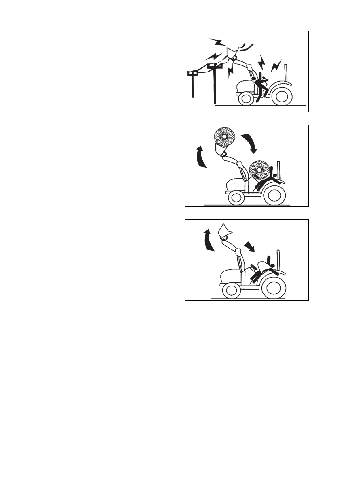
Do not allow the boom or attached adapter or equipment
SAFETY INSTRUCTIONS
26
to come into contact with electrical lines or other electrical
equipment. Electric current causes serious injuries or
death.
For safe handling of loads, always use a suitable type of
adapter for your work. While driving, keep the boom
loaded with a load at a low position above the mat. Failure
to do so may result in machine damage, serious injury or
even death.
U18N005_6
When mounting or dismounting the loader, secure all parts
that are attached to the adapter and the boom. The
adaptor or the boom may unexpectedly drop, which can
lead to injury or even death.
U18N005_7
U18N005_8

Towing safel
y
SAFETY INSTRUCTIONS
27
For the maximum permissible load of the hitch, see 'Maximum hitch load' in the Specifications section.
- Maintain a suitable speed taking into account the weight of the load towed or carried by the tractor and the
inclination of the surrounding terrain, remembering that the braking distances will be greater than that of
a unloaded tractor. Attached trailers or semi-trailers with or without brakes that exceed the specified
technically permissible maximum authorized weight may cause loss of control of the tractor unit.
- Always take into account the total weight of the attached machine and its load.
-When semitrailers are attached to the tractor, remember to switch all controls to neutral position, lock the
parking brake, turn off the engine, engage first gear (for mechanical transmission), and remove the ignition
key before leaving the operator's seat. ALWAYS secure the wheels of the tractor and the trailer with wedges.
The safest and recommended way to transport a damaged tractor is to transport it on a low-load trailer.
Always attach the tractor to the low-load trailer with chains. Before transporting the tractor on a low-load
trailer or on a railway wagon, make sure that the engine cover, door, openable roof (if available) and
windows are closed and securely locked. Never tow the tractor at a speed higher than 10 km/h. In this case,
the operator must remain in the operator's seat to drive and brake the tractor.
Caution: When a trailers is hitched to the tractor, before you leave the driving seat remember
to put all the controls in neutral, apply the handbrake, switch off the engine, engage first gear (if the
tractor has a mechanical transmission) and remove the key from the starter switch. If the tractor is
not parked on level ground, ALWAYS place chocks under the wheels of both the tractor and the
trailer For further information on safe working procedures, refer to the chapter 'Parking the tractor' in
the safe section of this manual.
ROPS (roll-over protective structure), sun visor and cab
are not FOPS protective structures (falling-object
protective structure).
It can never protect the operator from falling objects.
Avoid driving in dangerous terrain or areas where
a foreign object can fall on the roof of the cabin and injure
or even kill the operator.
U18N005_5
Falling Object Protective Structure (FOPS)
The term F.O.P.S refers to structure installed on the tractor intended to reduce the risk to the operator of
injury from falling objects during normal use of the vehicle.
Important:
z This tractor is equipped with a FOPS.
z The energy level of drop test is 1 365J.
Operator Protective Structure (OPS)
The term OPS refers to a protective structure installed on a tractor in order to minimize risk of operator injury
caused by objects penetrating into the operator position area.

Use of hazardous substances
SAFETY INSTRUCTIONS
28
European standard EN 15695-1 is applicable to the cabs of agricultural or forestry tractors and self-propelled
sprayers. The purpose of the standard is to limit the exposure of the operator (driver) to hazardous
substances when applying plant protection products and liquid fertilisers.
In accordance with the provisions of EN 15695-1 concerning cab classification, the measurement of
the internal positive pressure difference shall be made in accordance with ISO 14269-5:
1. Engine operating at rated speed;
2. Maximum air flow brought to the cab (closed recirculation);
3. Fan set to maximum speed.
The following terms and definitions are applied:
- Hazardous substances: substances such as dust, vapours and aerosols, with the exception of fumigants
which can be dispersed during the application of plant protection products and liquid fertilisers, which may
have a harmful effect on the operator.
- Dust general term identifying solid air-borne particles, finely divided and sedimented
- Aerosol: suspension of solid, liquid or solid and liquid particulate in agaseous medium with a negligible fall
rate (gener-ally less than 0.25 ms-1) Vapour: gaseous phase of a substance whose liquid or solid state is
stable at 20° Cand 1 bar (absolute). This cab, even when closed, does not protect against the inhalation of
hazardous substances. If the manufacturer's instructions for using these substances recommend personal
protective equipment, wear the equipment even in the cab.
Cabs are classified as follows:
Category 1: the cab does not provide protection against hazardous substances.
Category 2: the cab provides protection exclusively from dust.
Category 3: the cab provides protection from dust and aerosol.
Category 4: the cab provides protection from dust, aerosol and chemical vapours.
Danger: Use all the personal protective equipment suitable for the tasks in hand and relative
substances, in compliance with the requirements of statutory legislation in your country.

Use of Hazardous Substances
SAFETY INSTRUCTIONS
29
The category of the cab installed on this series of tractors, classified according to ISO 14269-5, is
listed below:
- Engine operating at rated speed
- Maximum air flow brought to the cab (closed recirculation) - with fan set to maximum speed
The manufacturer of your tractor has made every effort to make it as safe as is humanly possible.
Beyond this point it is the responsibility of the operator to avoid accidents and we ask that you read and
implement our suggestions for your safety.
Ensure that this tractor is only used by trained and authorized operators. Ensure that the operators are fully
familiar with the machine and understand all its controls and safety features. Operators should not operate
a tractor or attached machines or equipment if they are not properly trained or if they are physically unfit to
operate the machine. To avoid accidents, make sure that the operators wear clothes that might not get
caught in the moving parts of the tractor or the machine and, on the contrary, protect them from these
elements. When applying or using chemicals, ensure that clothes and protective equipment are used to
prevent breathing problems or skin irritation.
For detailed information contact the manufacturer of chemicals.
To avoid prolonged exposure to noise, ensure that the protection of ears is used.
If modification of the tractor or machine is necessary, ensure that the tractor or machine is stopped
beforehand.
When operating the tractor a certified roll-over protective structure (ROPS) must be used.
When operating the tractor a safety belt must be worn.
Under all circumstances, it is necessary to ensure the safety of the operator and others near the machine.
Ensure that no one is between the tractor and the towed vehicle (trailer or implement).
Ensure that this tractor is used only by trained and competent operators. Ensure that the operators are fully
familiar with the machine and understand all its controls and safety features. Operators should not operate
a tractor or attached machines or equipment if they are not properly trained or if they are physically unfit to
operate the machine. To avoid accidents, make sure that the operators wear clothes that might not get
caught in the moving parts of the tractor or the machine and, on the contrary, protect them from these
elements. When applying or using chemicals, ensure that clothes and protective equipment are used to
prevent breathing problems or skin irritation.
Technical data
CAB / ROPS
Category of cab protection against hazardous substances
Category 1

Safety tips during maintenance
SAFETY INSTRUCTIONS
30
1. Check all oil levels at least once a day. Check the amount of water in the radiator and the electrolyte
level in the battery and perform service according to the service schedule of the machine.
2. Ensure that the tire pressure is even and corresponds with the work to be performed.
3. Check that all preventive and service operations are properly performed on the tractor.
4. Ensure that adequate service facilities are available for maintenance and minor repairs.
5. Ensure that all service work and repairs are performed on flat concrete surface or similar surface. Do
not perform service work on the tractor until it is stopped, the parking brake is applied, and the wheels
are secured with wedges. If the tractor is started in an enclosed area, ensure that the area is well
ventilated as the exhaust fumes are very harmful and can cause intoxication or death.
6. It is forbidden to perform service work on the mounted equipment in the lifted position.
7. When changing wheels or tires, ensure that a suitable stand is placed under the axle before removing
the wheel and that the remaining wheels are secured with wedges.
8. If it is necessary to remove guards or covers when servicing or repairing, ensure that the guards or
covers are properly installed before starting the tractor.
9. Never fill the fuel near open flames or with an overheated engine. The engine must be stopped before
filling the fuel.
10. The cooling system operates under pressure, so be careful not to scald yourself with steam or hot
water when removing the hot engine radiator cap. Do not add water to the radiator when the engine is
hot. Only add water to the radiator after the engine has cooled down completely.
11. To prevent fire, keep the tractor, including its engine, clean and free from combustible material, at
a safe distance from fuel and other combustible material.

Mounting and demounting implements
.
SAFETY INSTRUCTIONS
31
1. Ensure that all assembly and disassembly of implements (attachments) is carried out on a secure,
level surface. To prevent accidental injuries, ensure that no one is between the tractor and the
implement or under the implement.
2. After mounting the implement, ensure that all hanging parts such as chains or hoses are properly
secured and, where PTOs are used, properly fastened and secured.
3. Where heavy implements are used, ensure that the unit is well balanced, using suitable ballast to
ensure this balance.
4. Before leaving the tractor, lower the implement onto the ground, deactivate the PTO, apply the
parking brake and stop the engine.
5. When working with an implement that uses PTO, make sure that no other persons are near the
moving parts and do not make any modifications to the implement while the machine is in operation.
6. A tractor equipped with a ROPS protective frame only performs its function in combination with
a fastened seat belt.
7. If children are present in the immediate vicinity of the machine or unit, caution and anticipation of
possible risks related to the movement and operation of the machine are necessary.
8. The tractor may only be used by trained operators who must ensure that no worker is injured. Extra
caution is necessary in dusty environment with significantly reduced visibility.
9. Never start the tractor unless the transmission is in the neutral position, the operator is in the driver's
seat, and there is no other danger when the engine is started up.
10. Only the operator sitting in the driver's seat can operate the tractor. Never turn or brake suddenly at
high speed, as this may cause the tractor to roll over, resulting in serious injury or death.
11. When driving on public roads, observe all legal requirements of the country in which the tractor is
operated, including the requirements for accompaniment. When driving with wide implements, use the
warning devices specified by the applicable legislation in the country in which the machine is used.
12. When operating under adverse conditions, in hilly or bad terrain, adjust the speed of the tractor to the
following conditions:
Never drive down the hill rashly or with the transmission in the neutral position.
Use engine braking capability together with service brakes.
Do not attempt to shift gears in a steep slope and engage a suitable gear before starting to drive the
tractor.
13. When driving uphill with a heavy implement, be careful to prevent overloading and loss of front axle
adhesion and consequent loss of control.
14. Never remove or modify the seat belt.
15. Never remove, modify or repair the ROPS protective frame.
PLEASE REMEMBER THAT A LITTLE BIT OF EXTRA CARE CAN PREVENT SERIOUS INJURY OR
TEATH AND AVOID DAMAGE TO YOUR TRACTOR

The following precautions are suggested to help prevent accidents
y
SAFETY INSTRUCTIONS
32
The best operator is the careful operator. Most accidents can be prevented by observing certain safety
measures. Before using the tractor, read the following measures and observe them to avoid accidents. The
tractor may only be operated by authorized persons who are properly trained for this operation.
Tractor
1. Read the operating and maintenance manual of the machine carefully before operating the tractor.
Insufficient knowledge of machine operation can lead to accidents.
2. For safe operation, use an approved protective structure and seat belt. Roll-over of a tractor without
a protective structure can result in serious injuries or even death.
3. Do not remove the roll-over protective structure (ROPS). Always use the seat belt.
4. The laminated roof of the tractor cab does not provide protection against the breakthrough of external
objects with higher weight.
5. To avoid falling while entering and leaving the cab, keep the stairs and platform clean, free of mud
and oil.
6. Do not allow anyone other than the operator to ride on the tractor. There is no safe seat or approved
passenger seat on the tractor.
7. Replace any missing, illegible or damaged safety signs.
8. Keep safety signs clean, free of dirt and grease.
Tractor service
1. For your safety, keep the tractor in good operating conditions. An inadequately maintained tractor can
be dangerous.
2. Stop the engine before servicing the tractor.
3. The cooling system operates under pressure. If the engine and its cooling system are hot, it is
dangerous to remove the cap. Turn the cap slowly to the stop, then let the pressure escape before
removing the cap.
4. Do not smoke while refueling the tractor. Never refuel the machine near an open flame.
5. The fuel in the injection system is under high pressure and can penetrate the skin. Unqualified
persons must not disassemble or modify the fuel pump, injectors, nozzles or other parts of the fuel
injection system. Failure to follow these instructions may result in serious injuries.
6. To prevent fire or explosion, keep the battery and the cold start devices away from open
flames.
7. Do not change or modify anything on the tractor and do not allow anyone to change or modify
thing on the tractor or any part of the tractor or its function.
an

Operating the tractor
SAFETY INSTRUCTIONS
33
1. Before starting the tractor, apply the parking brake, place the PTO lever in the 'OFF' position, the
hydraulic control lever in the lower position, the remote controls lever in the neutral position (if fitted),
and put the gear shift lever in neutral position.
2. Do not start the engine or controls while standing next to the tractor. Always sit in the tractor seat
when starting the engine or controls. To prevent the tractor from starting accidentally, a safety switch
is installed.
3. The starter system of the tractor is connected via this switch, which allows starting the tractor only
when the clutch pedal is depressed. On some models, the reverse shift lever and the PTO button
must also be in the neutral position to start the tractor. Do not bypass the starter safety switch. If the
safety switch fails, consult it with the Zetor dealer / distributor.
4. Avoid accidental contact with the gear shift lever while the engine is running. This may cause the
tractor to move unexpectedly.
5. Do not enter or leave the tractor while the tractor is moving.
6. Before leaving the tractor, stop the engine, remove the ignition key and engage the parking brake of
the tractor.
7. Do not operate the tractor in a closed building without proper ventilation. Exhaust fumes can cause
intoxication or death.
8. Do not park the tractor on a steep slope.
9. If the power steering or engine ceases to function, stop the tractor immediately and prevent it from
being used by others.
10. Only use the swinging drawbar or the drawbar of the lower link in the lower position for towing. Use
only the drawbar pin that is locked in that position. Towing by the tractor using the rear axle brackets
or any point above the rear axle may cause the front of the tractor to lift.
11. If the front of the tractor tends to lift while a heavy implement is attached to the three-point hitch, install
ballast on the front of the tractor or on the front wheels. Do not use a tractor with insufficiently
weighted front part.
12. Always use the hydraulics position control levers when attaching equipment / implements and
transporting equipment. Ensure that the hydraulic couplers are properly mounted and they disconnect
safely if the implement is accidentally released.
13. Never leave the equipment / implement in the lifted position.
14. Unless prevented by national or local regulations, when driving on public roads, day and night, use the
warning light / turn signal lights and warning triangles for slow-moving vehicles.
15. Low beam lights of the tractor used when passing oncoming vehicles at night. Check the adjustment
of the lights to prevent the driver of oncoming vehicles to be dazzled.
16. Emergency stop instruction: If the tractor does not stop when brakes are applied, pull the fuel cut-off
lever.
Tractor control
1. Watch where you drive,especially at the ends of the rows, the headlands, on the roads, around the
trees and at obstacles hanging low to ground.
2. To prevent the tractor from rolling over, drive the tractor at a safe speed, especially when driving on
uneven ground, when driving over ditches or slopes, and when turning in corners of areas and
parcels.
3. When driving on the road, do not disconnect the two brake pedals of the tractor from each other to
ensure better braking.
4. When driving downhill, shift the same gear in the tractor as uphill. Do not drive downhill with the
engine stopped or idling.
5. For safety reasons, any towed vehicle and/or trailer, the weight of which exceeds the maximum towed
weight, must be fitted with its own brakes.
6. If the tractor gets stuck or its tires are frozen to the ground, try to reverse to prevent the tractor from
rolling over.
Always make sure you have enough space above you, especially when transporting the tractor.

Operating the PTO
.
p
y.
SAFETY INSTRUCTIONS
34
1. When you operate the PTO-powered attachments, stop the engine and wait for the PTO to stop
before you leave the tractor and disconnect the equipment.
2. Do not wear loose clothing when operating the PTO or near rotating parts of the connected
implement.
3. When operating PTO-driven stationary equipment, always secure the tractor with the tractor parking
brake and secure the rear wheels from the front and rear side with wedges.
4. To avoid injury, always cover the PTO outlet. Do not clean, modify or repair the PTO-driven
equipment while the tractor engine is running.
Always make sure that the main PTO cover is installed and always install the PTO end piece cover
whenever the PTO is not in use
Diesel fuel
1. Keep the equipment clean and properly maintained.
2. Under no circumstances should gasoline, alcohol or blended fuels be added to diesel fire or explosive
hazard. Such blends are more explosive than pure gasoline. In a closed container, such as a fuel
tank. DO NOT USE THESE BLENDS.
3. Never remove the fuel cap or refuel the tractor with the engine running.
4. Do not smoke while refueling or when standing near fuel.
5. Maintain control of the fuel filler pipe when filling the tank.
6. Do not fill the fuel tank to capacity. Allow room for expansion.
7. Wipe up spilled fuel immediately.
8. Always tighten the fuel cap securely.
9. If the original fuel tank cap is lost, replace it with genuine cap. A none approved cap may not be safe.
10. Do not drive equipment near open fire.
11. Never use fuel for cleaning purpose.
12. Arrange fuel purchases so that winter grade fuel are not held over and used in the spring.
Note: It is suggested that after repairs if any of the safety decal/sign is peeled/defaced, the same may
be re
laced immediately in interest of your safet

DO'S AND DON'T'
S
Y
.
YES
.
SAFETY INSTRUCTIONS
35
DO'S-for better performance
Ensure that protective covers are returned immediately and
they are in good conditions.
YES Read all operating instructions before operating the tractor
YES Perform all maintenance tasks completely and without error.
YES Keep the air filter clean.
YES Ensure that lubricating oils of the appropriate standard and
quality are used and that they are refilled and changed at
recommended intervals
YES After replacing the filter elements, install new sealing rings.
YES Observe the warning light on the oil pressure gauge and if it lights up, check immediately for any
abnormality.
YES Make sure the radiator is always filled with clean water and use antifreeze in cold weather. Drain the
system only in case of emergency and refill before starting the engine.
YES Ensure the transmission is in the neutral position before starting the engine.
YES Store all fuel in clean environment and use a filter when filling the tank.
YES Perform minor adjustments and repairs as soon as necessary.
YES Allow engine to cool before removing radiator filler cap and adding water; remove the radiator cap
slowly.
YES Engage a lower gear when going downhill steep slopes.
YES Connect the brake pedals together when driving on the road.
ES If the draft control lever is not in use, keep it in the lower limit position

Don'ts - for safe operation
y
.
SAFETY INSTRUCTIONS
36
DO NOT USE the engine with the air filter disconnected.
DO NOT START the tractor in a closed building without proper ventilation
DO NOT OPERATE the tractor or engine during lubrication or cleaning
DO NOT LET the diesel fuel tank run out completely, otherwise the system will need to be bled.
DO NOT INTERFERE with the engine injection pump. The warranty is void if the seal is broken
DO NOT LET the engine idle for a long time.
DO NOT RUN the engine if all cylinders do not work.
DO NOT DRIVE with the clutch or brake pedal depressed. This leads to excessive wear of the brake lining,
clutch-driven elements and clutch release bearing.
DO NOT USE independent brakes to turn while driving on the road or at high speed.
DO NOT REFILL the fuel in the tractor with the running engine.
DO NOT SET the hydraulic control levers beyond the upper stop limit.
DO NOT USE the draft control lever to lift implements.
DO NOT START the engine with the PTO engaged.
DO NOT USE the hand throttle control lever while driving on the road.
DO NOT MOVE the h
draulic levers backwards
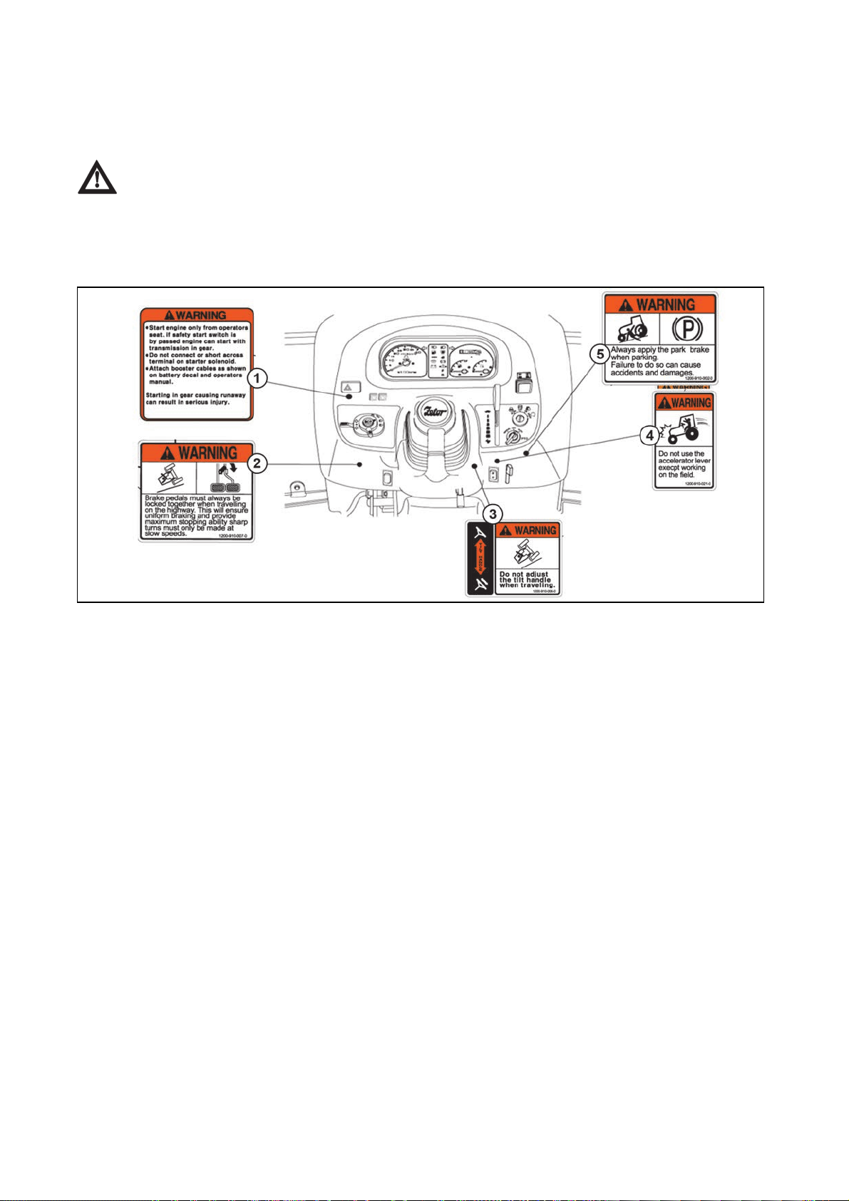
General safety informatio
n
y
SAFETY SIGNS
37
(Replace all missing, damaged or illegible signs)
IMPORTANT: This ''General safety Information'' should be kept with the machine at all times as reference
data.
This symbol means ATTENTION! YOUR SAFETY IS INVOLVED. The message that follows the
symbol contains important information about safety. Follow recommended precautions and safe
operation practice.
Decals on the dash cover
U18N006
1- Warning:
z Start the engine only from the driver's seat. If the starter switch is disabled, the engine can be started.
z Do not connect the terminal block on the starter solenoid.
z Connect the booster cables as shown on the battery plate and in the Operator´s manual.
Shifting a gear that causes uncontrolled tractor movement can result in serious injury.
2- Warning:
When driving on the road, brake pedals must always be connected together. This ensures even braking and
provides maximum braking performance. Sharp turns must be performed at moderate speeds.
3 - Warning:
Do not adjust the seat while driving.
4 - Warning:
Do not use the accelerator lever except for field work.
5 - Warning:
Always apply the parking brake when parking.
Failure to do so ma
result in accidents, damage and personal injury.

Decals on the chassis
SAFETY SIGNS
38
U18N007
1 -Operator´s manual of the tractor
2 - Warning:
Push the button into the locked position with the front loader control joystick lever in the neutral position,
whenever the implement is not in use.
3 - Warning:
Never use the differential lock at high speed or on the road, as it may cause damage to the machine, risk to
road safety or cause accidents and injuries to persons.
4 - Warning:
Always lock the hydraulic circuit control when:
1. You drive on the road.
2. You perform maintenance / change working implements.
3. You set up the machine. Sudden lowering of the implement can cause serious injuries or death.
5- Warning:
Always use the seat belt.
6 - Danger:
If heating and air conditioning is used, regular ventilation is required to avoid suffocation. It is forbidden to
sleep in the cab.
7 - Warning: Work in ventilated areas.

Decals on the cabi
n
SAFETY SIGNS
39
U18N008
1- Warning:
Do not remove the radiator cap while the engine is hot. Hot steam can cause injuries.
2 - Caution:
Do not touch the engine and cooling system while it is hot. It may cause severe burns.
3 - Warning:
Do not refuel the tractor near an open flame or other source of danger, nor smoke when handling fuel.
Always switch off the engine before refueling the tractor.
4 - Danger:
Only the operator can be transported on the tractor.
5 - Warning:
Do not move the gearshift lever to H position when reversing.
6 - Internal / external air ventilation:
z If the rear and side grilles are open, the internal air will be recirculating.
z For short-term efficient use of heating or air conditioning, use air recirculation, then close the rear and
side grilles.
7 - Caution:
Be careful not to get your hand or clothing into the rotating radiator fan or belts, otherwise serious injury may
result.

U18N009
p
SAFETY SIGNS
40
1- Warning:
Only attach implements and trailers to the tractor using the prescribed drawbar or hitch.
2- Danger:
Contact with the rotating shaft may cause injuries or death.
Stay away!
When operating, keep all the covers of the shaft, tractor and connected device mounted.
3- Warning:
away from lifted arms and other parts of the loaders and implements.
Kee

Some of the universal symbols have been shown below with an indication of their meaning.
UNIVERSAL SYMBOLS
41
Engine
speed rev/minX100
Hours, recorded Continuous variable
Engine coolant
temperature
Fuel level Hazard warning
Engine stop control Neutral Turn signal
Lights Fan
Pressured-open slowly Corrosive substance
''Tortoise'' Slow or
minimum setting
Warning
setting
pressure
temperature
''Hare'' fast or maximum
Transmission oil
Transmission oil
Horn Power take off engaged Parking brake
Engine oil pressure
Air filter Lift arm/raise Differential lock
Battery charge Lift arm/lower See operator's manual
disengaged
Power take off
Work lamps

NOTES
42

Description of tractor controls
CONTROLS, INSTRUMENTS & OPERATIONS
43
The following pages in this section detail the location and function of various instruments, switches and
controls on your tractor. Even if you operate other tractors, you should read through this section of the
manual and ensure that you are thoroughly familiar with the location and function of all the features of your
new tractor.
Do not start the engine or attempt to drive or operate the tractor until you are fully accustomed to all the
controls. It is too late to learn once the tractor is moving.
Particular attention should be paid to the recommendations for running-in to ensure that your tractor will give
long life and dependable service for which it was intended.
If in doubt about any aspect of the operation of the tractor consult your ZETOR tractor dealer / distributor.
Battery disconnector
UCL18NN012
The battery disconnector is located on the front axle bracket under the right front corner of the hood (A).
Turn the battery disconnector handle in the direction of the arrow (B) to disconnect the battery from the
tractor's electrical installation. To connect the battery to the tractor's electrical installation, turn the battery
disconnector handle counterclockwise. Battery connection is indicated by a visible green field (1).
(C) The position of the battery disconnector handle when the battery is connected.
(D) The position of the battery disconnector handle when the battery is disconnected.
When the tractor is parked, disconnect the battery using the battery disconnector (1). If the
tractor is parked for a long period of time, it is necessary to recharge the battery at least once
a month due to self-discharge.
When the engine is switched off, the engine control unit remains active for about 2 minute
because of storage of operation data. During this time the supply of current from the accumulator
must not be interrupted. Do not disconnect the accumulator before this time expires.
After connecting the battery using the battery disconnecting switch, wait at least 30 seconds
before turning on the ignition key.

Instrument and switches
y
CONTROLS, INSTRUMENTS & OPERATIONS
44
U18NN010
1 - Left Turn Indicator
2 - Tachometer
3 - Load Sensing Button
4 - Warning Lights Switch
5 - Cruise Control Button
6 - Horn Switch
7 - Turn Signal Switch
8 - Headlight and Beacon Light Switch
9 - Progressivity Setting (Sensitivity Switch)
10 - Steering Wheel Adjustment Lever
11 - Speed Control of Cruise Control
12 - Parking Brake Lever
13 - PTO Mode Control
14 - Key Switch
15 - PTO Switch
16 - Hand Throttle Lever
17-Temperature Display
18 - Fuel Gauge
19 - Left Turn Indicator
20 - Air Pressure Gauge, only for tractors equipped with trailer air brakes
21 - Temporar
Trailer Brake Deactivation Button, only for tractors equipped with trailer air brakes

Main switch (key switch)
CONTROLS, INSTRUMENTS & OPERATIONS
45
[OFF]- The key can be inserted or removed.
[ON]- The electric circuit is on.
[GLOW] - Glow plugs preheat the com-bustion chamber.
[START]- The starter motor is engaged.
When the key is released it will return to the ON position.
1 - Glow
2 - Off
3 - On
4 - Start
Headlights, turn signal lights, beacon and horn switch
Front light switch
High beam and low beam lights are controlled by the main switch
Position 3 - high beam light and beacon light
Position 4 - low beam light and beacon light
U18N011
Turn signal light switch
Pull down the turn signal light lever to activate the left turn signal light.
Push up the turn signal light lever to activate the right turn signal light.
Horn
Press the red button.
Beacon
The beacon is switched on simultaneously when the low
beam lights or high beam lights are switched on
- positions 3 and 4
U18N012

Tachomete
r
CONTROLS, INSTRUMENTS & OPERATIONS
46
This meter shows the revolutions of the engine and the
PTO shafts as well as the travel speed in top gear.
Hour meter
The operating hour meter consists of digits where the last
digit indicates 1/10 of an hour. It shows the number of
operating hours of the tractor.
The indicator light at the bottom of the operating hour
meter should flash during operation to indicate that the
system is operating properly.
U18N014
Fuel gauge and water temperature gauge
Fuel gauge
Shows the amount of fuel in the tank when the ignition
switch is ON.
Water temperature gauge
Shows the water temperature with the ignition switch ON.
C is low to normal temperature.
H is high temperature.
If the pointer is in the red H segment the engine is
overheating.
Refer this book to rectify the problem.
Hazard warning signal switch
Push the hazard warning signal once to operate the
hazard warning light. (Left and right turn indicators flash).
Push the hazard warning light switch again to switch off
the hazard warning lights.
1 - Hazard warning signal S/W
UCL18N013
U18N015
UCL18N015

Warning lights
CONTROLS, INSTRUMENTS & OPERATIONS
47
The high beam indicator light comes on on the instrument panel.
The low beam indicator light comes on on the instrument panel.
U18N017
The parking brake lights up when the tractor is braked with the manual parking brake.
PTO monitor lamp Shows the revolution of PTO.
Fuel Level If it comes on while the engine is running, fill the tank with fuel.
The oil pressure indicator light turns off when the engine starts, in case the oil pressure is OK. If
it comes on while the engine is running, stop the engine and contact a specialized service.
Charge lamp
This light will go off as soon as the engine starts to run to indicate that the alternator is changing.
(Please note, as broken fan belt can cause the light to come on, please stop the engine as
overheating can occur if not rectified immediately)
The glow indicator light indicates preheating when starting at low temperatures.
Cruise Control Lamp
Will turn on when cruise control is engaged.
The Forward F indicator light comes on when the forward travel pedal is depressed. The
Forward R indicator light comes on when the backward travel pedal is depressed.
The indicator light comes on when the start key is in ON position and the safe start conditions
are not met.
Conditions for safe start:
1. The brake pedal is depressed.
2. The PTO ON / OFF switch is in the OFF position.
If the light comes on when safe start conditions are met, there is a problem with one of the
electrical parts of the machine.
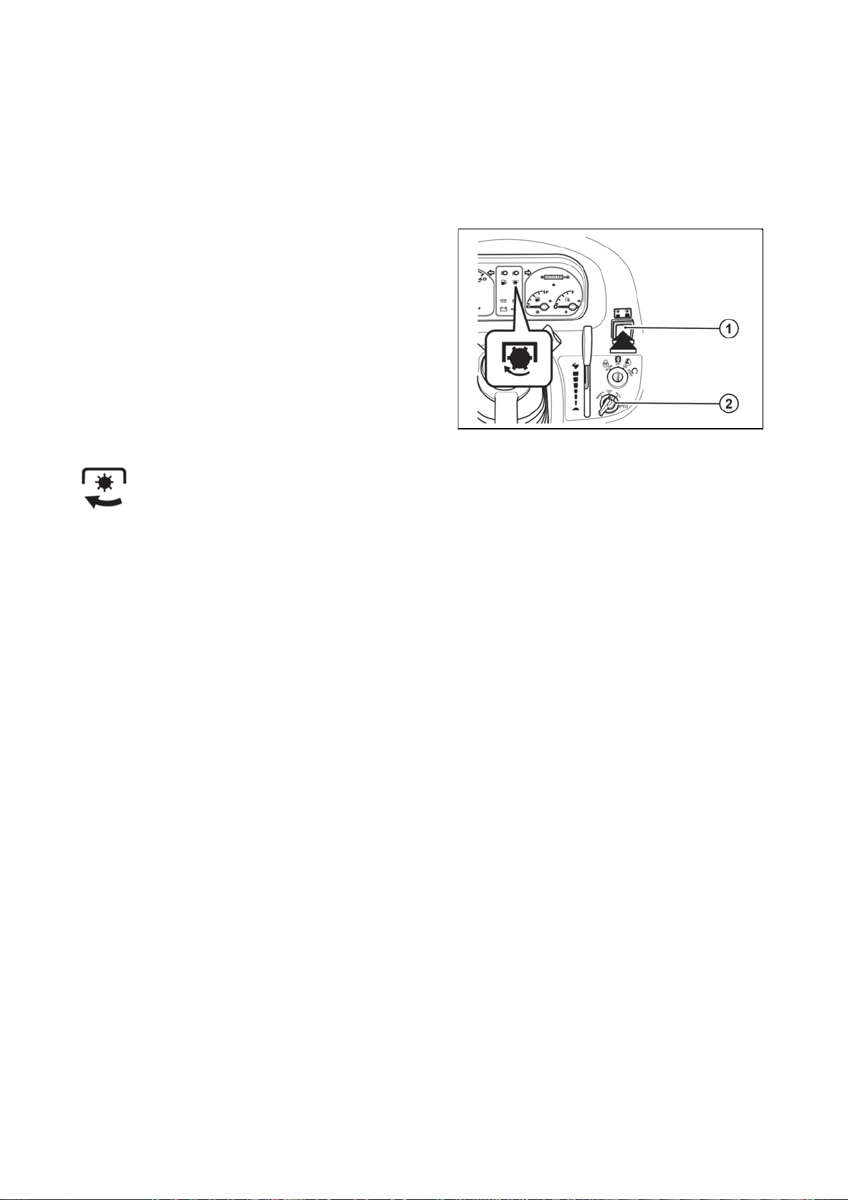
Independent PT
O
n
CONTROLS, INSTRUMENTS & OPERATIONS
48
Your tractor is equipped with 2 Speed rear PTO to suit range of applications and conditions.
Use the PTO switch to engage or disengage rear PTO.
If the driver leaves the seat or is out of the driver's seat while the PTO is operating, the PTO indicator lamp
flashes and emits an audible signal and the PTO stops operating.
Two switches operate the independent PTO.
1 - PTO O
-Off S/W
2 - PTO Mode S/W
UCL18N017
The PTO indicator lighton the instrument panel indicates the PTO status.
1. If the indicator light is on: PTO rotates.
2. If the indicator light is off: PTO is off.
3. If the indicator flashes: PTO is not currently in motion, but shall be activated when the clutch pedal is
released or the implement is lowered.
1. ON/OFF SWITCH FOR PTO: The PTO ON / OFF switch is located on the right side of the steering
column and can be easily identified by the built-in red indicator light.
When the switch is pressed, the PTO indicator lights up to indicate that the PTO switch and PTO are both in
the ON position. If you press the switch again, the light turns off, indicating that the PTO is off.
2. PTO CONTROL SWITCH: This switch is located near the starting key location on the dash panel. There
are three positions marked for this switch.
z OFF at the center
z MANUAL at the left
z AUTO AT THE RIGHT.

The PTO does shall not rotate when one of the two switches is in the OFF position
CONTROLS, INSTRUMENTS & OPERATIONS
49
The following table explains how the PTO operates in two different positions (Manual & Auto) of the PTO
control switch with the PTO ON / OFF switch in the ON position.
PTO
ON/OFF
Switch
PTO
Control
Switch
Hydraulic Position
Control Lever.
PTO Monitor
Lamp on the dash panel
PTO SHAFT
Manual
On
Either raised or lowered Glows Rotates
Mode
On
On
On
Auto
Mode
Auto
Mode
Auto
Mode
z The table above provides information on PTO safety functions. If the indicator light on the instrument
Either raised or lowered Blinks Stationary
Raised Blinks Stationary
Lowered Glows Rotates
panel flashes, this indicates to the operator that the PTO is in the ON position but is not currently
rotating temporarily because the implement is lifted.
The PTO starts to rotate immediately when the implement is lowered.
z The operator must observe the warning signal in order to ensure that there are no other persons or
bystanders in the area around the tractor, as rotating parts of some implements may accidentally
cause injury to persons near the tractor.
z Stopping the PTO when lifting the implement while controlling position shall prevent damage to the
implement or PTO.
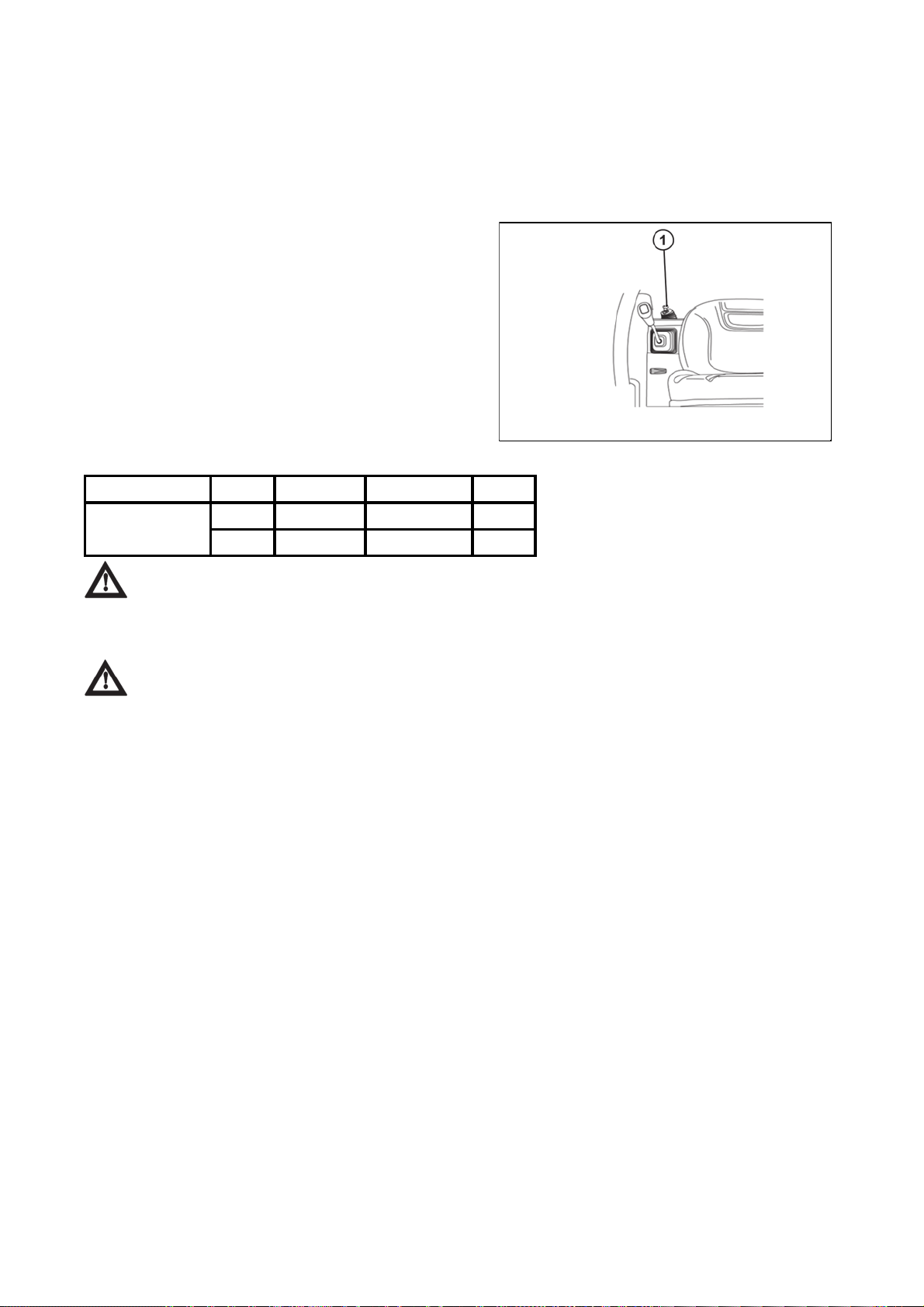
PTO shaft revolutions 540 and 1000 rpm shifting leve
r
CONTROLS, INSTRUMENTS & OPERATIONS
50
The rear PTO shift lever is located on the left side under the driver's seat and can be moved to the upper
position (540 rpm) or to the lower position (1,000 rpm) from the center, neutral position, according to the
specification of the attached implement.
In no case shall the specified speeds be exceeded, as this may result in serious damage to the tractor /
attached implement.
When the PTO is not in use, the gear shift lever must be placed in the neutral position to prevent accidental
lowering.
1 - PTO Shift Lever
U18N032A
Model Position PTO (RPM) Engine (RPM) Remark
UTILIX HT 45/55 1 540 2,608
2 1,000 2,500
Caution: Do not operate any implement at a high speed than is specified for it. When making
adjustments to the implement stop the engine to avoid serious injury. When leaving the tractor stop
the engine, and remove the key. Set the parking brake.
Warning:
1. When working with a rotary implement on hard ground, the PTO switch must be set to the OFF
position to prevent the PTO from rotating. If this is not done, the rotating implement blades
come into contact with the hard ground under the implement, causing the entire tractor to
move. This accident can result in serious injury or even death.
2. When using PTO-driven implements, special precautions must be taken to ensure that no
persons or bystanders are in the area around the tractor. Contact with rotating implement
blades can result in serious injury. The warning signaled by the PTO flashing indicator light
allows the operator to remember that the PTO is in the ON position and will start rotating
immediately when the clutch pedal is released or the implement is lowered (or both).
3. The rotational speeds specified by the implement manufacturer must not be exceeded under
any circumstances, as this could result in serious damage to the tractor / implement and / or
serious injury to bystanders.

Connecting and disconnecting implement
CONTROLS, INSTRUMENTS & OPERATIONS
51
If the PTO is used, remove the cover (1) from the PTO
shaft.
Connect the lower left link, then connect the lower right
link using the adjusting handle, if necessary.
Connect the upper link.
Connect the PTO shaft to the tractor and make sure it is
properly locked in place.
Adjust the stabilizer bars so that it corresponds to the
implement and tighten the retaining nuts.
To disconnect the implement, proceed in the reverse
order.
U18N048
Caution: Do not attach a PTO shaft while the engine is running and ensure all safety shields
are in place.
Caution: Be especially careful when working with an aggregated implement near other people
or vehicles. Take into account the overall width of the unit to prevent traffic accidents.
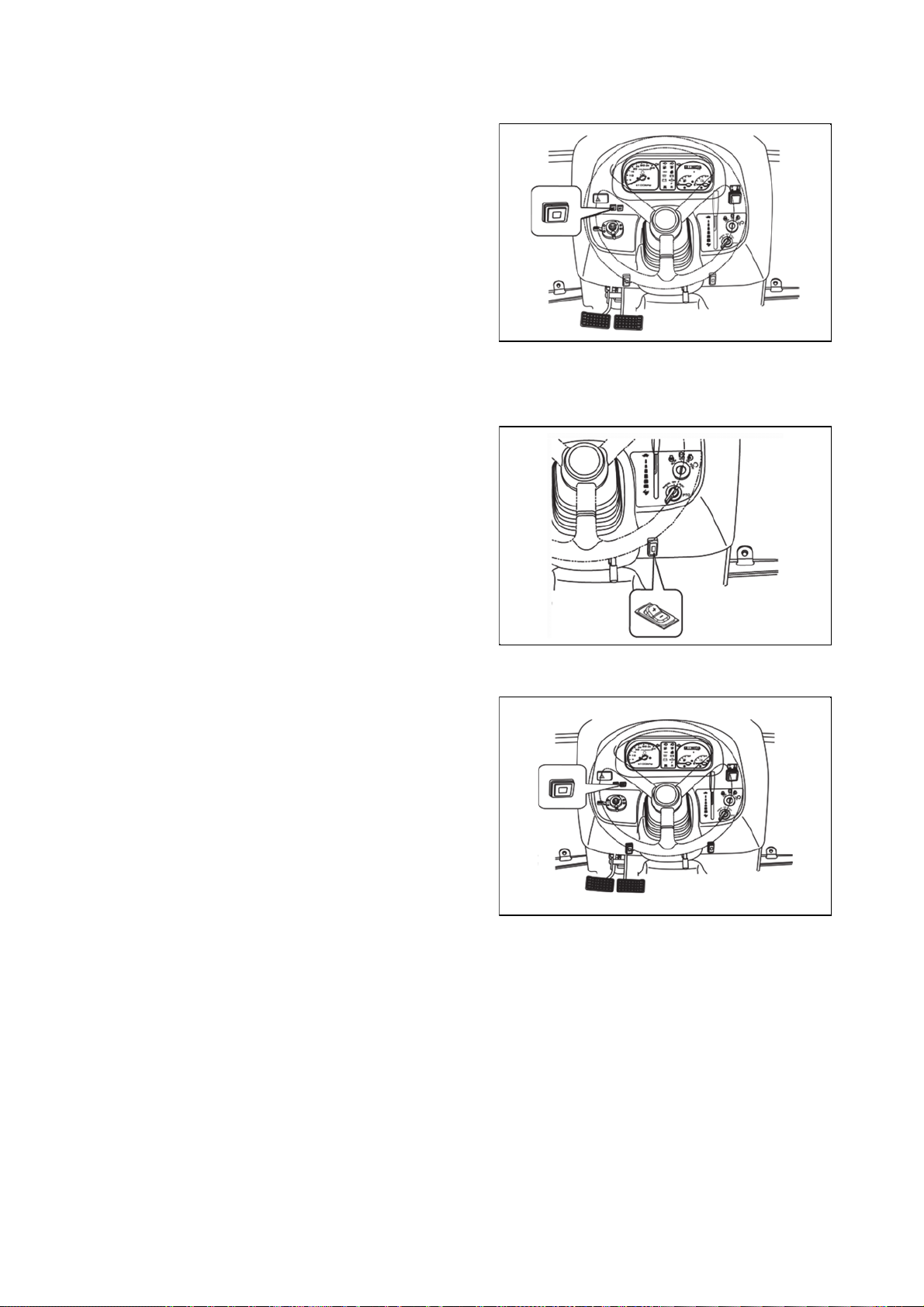
Cruise control butto
n
CONTROLS, INSTRUMENTS & OPERATIONS
52
z Engaging Cruise Control
- Depress the forward speed control pedal until the
required speed is achieved.
- Press the cruise control button to engage cruise
control.
- Release the forward speed control pedal.
- The cruise control is only operational when the
machine is traveling forward.
z Disengaging Cruise Control
To disengage the cruise control you can either
press the cruise control button or depress the brake
pedal.
Cruise speed control switch
The cruise control speed can be increased and decreased
when the cruise control function is activated.
To increase the cruise control speed by a certain
increment, press and release the upper part of the cruise
control (+) switch. Press and release again to increase
cruise control speed by one more step.
To decrease the speed by a certain increment, press and
release the lower part of the cruise control (+) switch.
Press and release again to decrease cruise control speed
by one more step.
The setting is canceled when the cruise control function is
deactivated.
Load sensing button
The load sensing function is used to prevent the motor
from stopping at high load.
Press the load sensing button to activate the load sensing
function.
If the engine speed is less than 2000 rpm, the engine
speed shall be 2000 rpm.
If the engine speed is higher than 2000 rpm, the engine
speed shall be maintained at this level.
If the engine speed decreases below the set range, the
control adjusts the hydrostatic transmission ratio to avoid
engine choking. The higher the engine load is, the more
engine revolutions and speed are reduced.
Press the button again to deactivate the load sensing
function.
U18N020
U18N021
U18N022
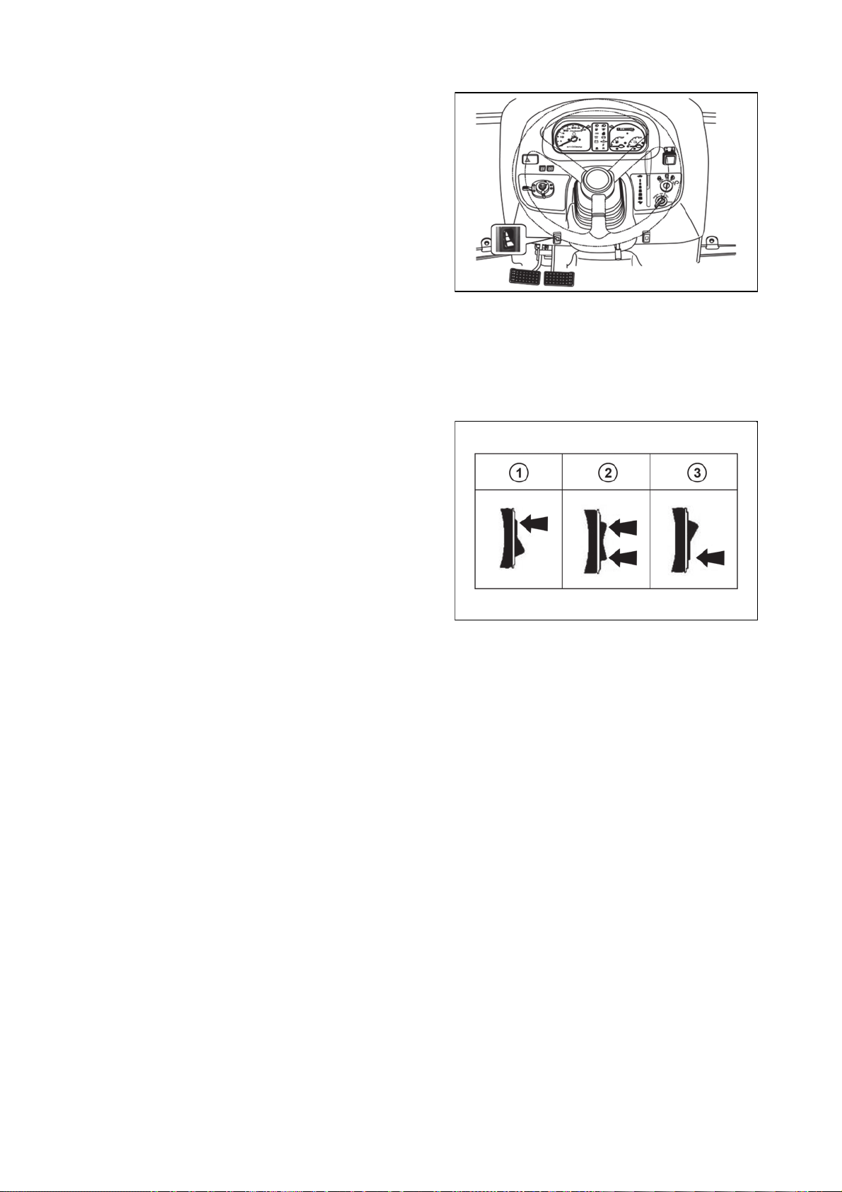
Mode (sensitivity) switc
h
CONTROLS, INSTRUMENTS & OPERATIONS
53
The tractor allows the user to select the response
sensitivity in three different modes.
z Mode 1
To activate mode 1, fully press the top of the mode
switch. This mode provides greater response
sensitivity when controlling pedal movement.
This results in faster changes of speed or direction.
The movement of the tractor may not be smooth in
this mode.
z Mode 2
To activate mode 2, fully press the top or bottom of
the mode switch. This mode provides moderate
response sensitivity when controlling pedal
movement, which is typical of standard operating
conditions.
z Mode 3
To activate mode 3, fully press the bottom of the
mode switch. This mode provides less aggressive
response when controlling pedal movement.
1 - Mode 1
2 - Mode 2
3 - Mode 3
U18N023
U18N024

Tractor controls
CONTROLS, INSTRUMENTS & OPERATIONS
54
U18NN025
1 - Brake Pedal
2 - PTO Speed Selection Lever
3 - Gearshift Lever
4 - 4WD Shift Lever
5 - Hand Throttle Lever
6 - Parking Brake Lever
7 - Steering Wheel Adjustment Lever
8 - Forward / Reverse Travel Pedal
9 - Front Loader Control Lever
10 - Draft Control Lever
11 - Position Regulation Lever
12 - Sectional Control Lever - External Hydraulic Circuits
13 - Differential Lock Pedal

Hand throttle (Throttle lever)
CONTROLS, INSTRUMENTS & OPERATIONS
55
1 - Throttle Lever
Pulling the hand throttle towards the driver reduces the
speed.
Pushing the hand throttle away from the driver increases
the speed.
Speed and direction control pedals
The speed and direction control pedals are located on the
right side of the cab floor.
To drive forward, depress the forward speed control pedal.
To reverse, depress the reverse speed control pedal.
Once the speed control pedal is released, it returns to the
neutral position and the tractor stops.
UCL18N020
The braking effect of a hydrostatic transmission
is considerably different from a classical mechanical
transmission. When the pedal is released, the speed
changes instantly depending on its position; i. e. more
intense and immediate deceleration of the machine. It
is therefore necessary to avoid violent and reckless
handling of the pedals.
U18N027
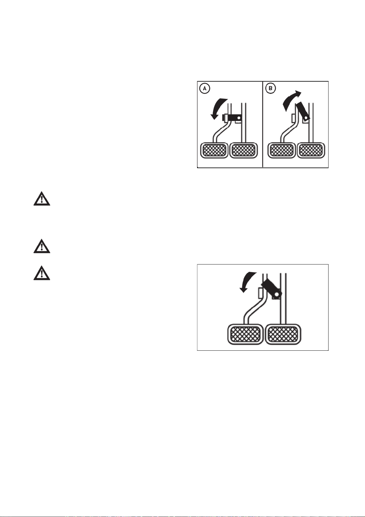
Foot brakes
CONTROLS, INSTRUMENTS & OPERATIONS
56
When depressing both pedals connected by a latch, both rear wheels are braked.
When one brake pedal is depressed after the latch is released, only one rear wheel is braked, depending
which brake pedal is depressed. The right brake pedal brakes the right rear wheel, the left brake pedal the
left rear wheel.
Braking with one brake pedal is used to make the tractor's off-road turns easier. When turning is complete,
the brake pedals must be again latched together.
A - Brake pedals connected by a latch
B - Brake pedal latch disconnected
U18NN015
When driving on the road, both pedals must be connected by a latch. Disconnect the right or
left wheel brakes only when working off-road and in the field.
Note: When driving down a steep slope with a trailer or semi-trailer equipped with brakes, the foot brake
must be applied from the beginning of the descent!
When braking with one brake pedal, the trailer brakes are not engaged!
Caution: A connecting latch is provided to
connect the right and left brake pedals for high speed
or road use. In the interest of safety always use it on
the road or at high speed as using one side only can
cause rollovers. When servicing the tractor ensure
that the adjustment on both sides in the same.
U18NN014

Parking brake leve
r
.
CONTROLS, INSTRUMENTS & OPERATIONS
57
With the connected brake pedals depressed, lift the
parking brake lever (1) upwards and release the brake
pedals.
The parking brake lever remains lifted and the brake
pedals are depressed. This brakes the tractor.
To unbrake the tractor, depress the brake pedals, the
parking brake lever (1) shall move to the lower position
and the brake pedals shall return to the upper position
when released. This unbrakes the tractor
U18NN022_1
Important: Traveling with the parking brake on will damage the brakes.
To avoid personal unjury:
z When leaving the tractor, make sure that you have applied the parking brake and switched off the
engine.
z When using the brakes:
- To use the tractor, make sure that the parking brake is released. Improper use of the brakes can
damage the transmission.
Air brakes of trailers and semi-trailers
The control of the air brakes of trailers (semi-trailers) and the control of the tractor brakes is designed in such
a way that the braking effect of both vehicles is synchronized.
Air pressure indication
The air pressure in the trailer or semi-trailer air brakes is
indicated by an air pressure gauge located on the
instrument panel.
If the air pressure gauge needle is in the red field, the air
pressure in the trailer or semi-trailer air brake system is
low.
If the air pressure gauge needle is in the green field, the
value of the air pressure in the trailer or semi-trailer air
brake system is correct.
If the air pressure gauge needle is in the yellow field, the
air pressure in the trailer or semi-trailer air brake system is
high, this is a malfunction, contact a service immediately.
UCL18NN016
When driving a tractor with a trailer or semi-trailer with air
brakes, the air pressure gauge needle must be in the
green field.
If the pressure gauge needle of a tractor with attached trailer or semi-trailer with air brakes
drops into the red field, the tractor with trailer or semi-trailer with air brakes must not continue to
travel. It is necessary to stop the unit and wait until the air pressure increases and the pressure
gauge needle is within the green field of the pressure gauge.

The button for temporary deactivation of brakes of the trailer or semi-traile
r
p
.
).
CONTROLS, INSTRUMENTS & OPERATIONS
58
The temporary trailer or semi-trailer brake deactivation button (1) is located on the dashboard panel.
The button for temporary deactivation of brakes of the
trailer or semi-trailer can be used by the operator of the
tractor with the connected trailer or semi-trailer to make
sure that the effect of the parking braking system of the
tractor with the connected trailer or semi-trailer when the
tractor is braked with the hand brake is sufficient.
If there is a tractor with the connected trailer or semi-trailer
which is braked with the hand brake and the key in the
switch box is in the position (I), and we press the button
for temporary deactivation of brakes of the trailer or semitrailer, the trailer or semi-trailer is deactivated for the time
when the button is pressed (the trailer or semi-trailer does
not brake). When the button for temporary deactivation of
brakes of the trailer or semi-trailer is released, the brakes
of the trailer or semi-trailer are activated (the trailer or
semi-trailer brakes
Prior to using the button for temporary deactivation of brakes of the trailer or semi-trailer, it is
always necessary to provide sufficient space in front of the tractor and behind the connected trailer
or semi-trailer where no obstacles or persons will be present for the case that the effect of the
arking braking will not be sufficient and the combination of vehicles moves
Only the air brakes are deactivated by the button for temporary deactivation of brakes of the
trailer or semi-trailer.

One-hose and two-hose brakes
CONTROLS, INSTRUMENTS & OPERATIONS
59
1. clutch head of one-hose brakes
2. clutch heads of two-hose brakes
Clutch heads after disconnection or without
a connected trailer, articulated trailer must be closed
by a valve.
One-hose brakes
The coupling head of a single-hose air brake has a flap
marked black.
The coupling head marked black serves both for filling and
controlling for the single-hose air brake system of the
trailer or semi-trailer.
The maximum permitted speed of the unit is
given by the maximum permitted speed of the slower
unit vehicle.
UCL18NN018
Two-hose brakes
The left-hand flap (1) is marked yellow (braking line), the
right-hand flap (2) is red (filling line).
The maximum permitted speed of the unit is
given by the maximum permitted speed of the slower
unit vehicle .
UCL18NN019
UCL18NN020

Sub gear lever (Linear shift lever)
CONTROLS, INSTRUMENTS & OPERATIONS
60
1 - Sub gear lever
H highest gear (fastest)
M medium gear
L lowest gear (slowest)
Diff-lock pedal
1 - Diff-lock pedal
In case of wheel slippage use the diff-lock by pushing
down on the diff lock pedal.
To release it remove the foot from the pedal.
U18N029
UCL18N026
Danger: Tractor will be difficult to turn if the diff-lock is engaged, ensure the lock is
disengaged before turning the steering wheel.
Important: Do not use high engine speeds when turning on the differential lock. If the
differential lock is not released after the foot is removed from the differential lock pedal, apply the left
or right brake alternately until it is disconnected.
Caution: Never use the diff lock at high speed or on the road as this can cause roll over and
injury.

Front Axle Drive Leve
r
prop
.
CONTROLS, INSTRUMENTS & OPERATIONS
61
Using front-wheel drive improves passability in difficult terrain and the traction of the tractor.
1 - Front Axle Drive Lever
In the ON position the front axle drive is connected and in
the OFF position the front axle drive is disconnected.
Activate and deactivate the front axle drive when driving
straight at low engine speeds.
U18N031
Important: Do not use front wheel drive at high speed or on the road as premature wear of
components will result.
Important: Always use the clutch when shifting the front axle drive.
Driver's seat
1 - Seat belt
2 - Forward / backward adjustment lever
3 - Knob for weight adjustment
4 - Seat back angle adjustment lever
To adjust the seat backwards and forwards lift the lever at
the front of the seat and set it to the desired position.
Caution: Check whether the seat
erly locked in its position before driving the tractor
UCL18N027

Tilt leve
r
CONTROLS, INSTRUMENTS & OPERATIONS
62
1 - Tilt lever
U18NN028
To adjust the inclination of the steering wheel with a 3 stages and set it to the desired position.
Danger: Ensure that the tilt pedal has locked before moving the tractor.

Operating the hydraulics
CONTROLS, INSTRUMENTS & OPERATIONS
63
The hydraulics are powered with an engine driven hydraulic pump and controlled with a position control lever
mounted beside the driver.
Danger: When working with the three-point hitch, it is necessary to stay away from the radius
of lift arms and all connected equipment. This eliminates the risk of injury in case of improper
handling.
Position control
1 - Position Regulation Lever
The implements can be raised and lowered using the
position regulation lever and can be stopped at any
position by stopping the lever shift.
To ensure a constant working depth, an adjustable stop
can be used to ensure that the implement always returns
to the same depth.
U18N033
To raise the implements: Pull the lever backwards
To lower the implement: Push the lever forwards.
Warning: After finishing the work, always lower the implement to the ground and switch off the
engine, set the parking brake to avoid injuries and accidents.
Internal hydraulic circuit control lever
1 - Draft Control Lever
2 - Floating position
3 - Draft Control Range
4 - Lifting
For precise work, the soil tillage implement can be
adjusted using draft control. When the lever is moved
forward, the depth increases. When the lever is pulled
back, the depth decreases.
U18N034
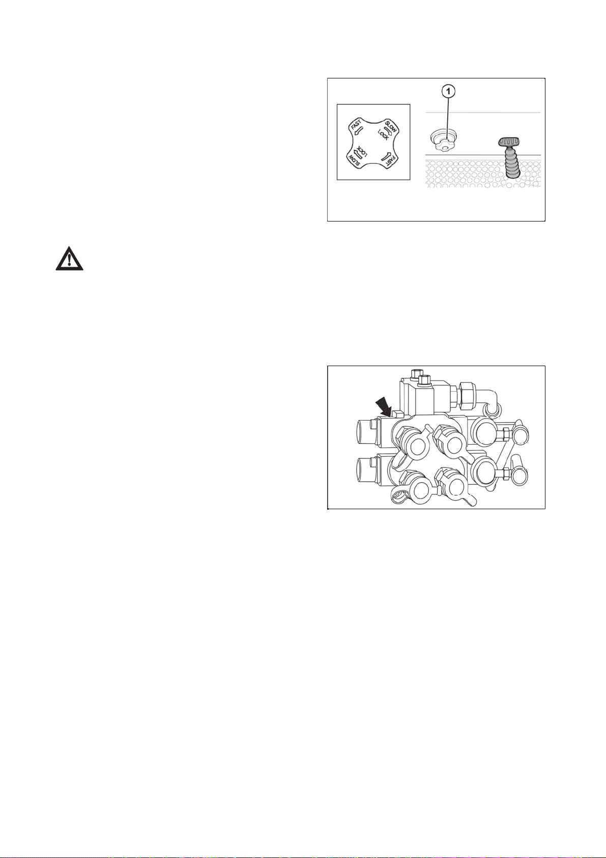
Lowering speed control knob for the 3 point hitc
h
CONTROLS, INSTRUMENTS & OPERATIONS
64
1 - Three-Point Hitch Lowering Speed Control
This knob controls the downward speed of the hydraulics
three point linkage and positioned at the front of the
driver's seat.
To slow the downward speed - turn the knob clockwise.
To increase the downward speed, turn the knob
anticlockwise.
To lock the knob clockwise.
Do not over tighten the knob.
U18N035
Caution: Always set the knob to lock when
1. Traveling on the road
2. Replacing tires or blades on an implement.
3. Making adjustments to an implement. Sudden dropping of an implement due to hydraulic
problems can cause serious injury or death.
Outer hydraulic circuit
It supplies pressure oil for hydraulic devices on outer
drives of hydraulics ended with couplers. Coupler sockets
with 12.5 mm bore are in accordance with the international
recommendation of ISO.
UCL18NN028

Outer hydraulic circuit controls
CONTROLS, INSTRUMENTS & OPERATIONS
65
The SCVs quick couplers are operated by levers (1) and (2) located on the panel on the right side of the
driver's seat.
UCL18NN029
By moving the lever (1) forward, pressure oil is supplied to the quick coupler (1A).
By moving the lever (1) backwards, pressure oil is supplied to the quick coupler (1B).
By moving the lever (2) forward, pressure oil is supplied to the quick coupler (2A).
By moving the lever (2) backwards, pressure oil is supplied to the quick coupler (2B).
Important:
As soon as the implement operated by the pressure oil from the quick couplers reaches the end of the
stroke, return the lever to the middle (neutral) position, when there is no oil pressure in the quick couplers;
otherwise the oil will flow through the relief valve. When the oil is pushed through the relief valve for a longer
period of time, oil becomes overheated. When using the tractor hydraulic system to drive the front loader, do
not use the SCVs and the loader at the same time.
Remote hydraulic control valve coupler connecting and disconnecting
When connecting and disconnecting the quick-couplers pay increased attention with regard to
the residual oil that remains in the socket or on the plug of the quick-coupler. For environmental
reasons after every disconnection of quick-couplers this residual oil must be removed with any
textile material.
Connection
1) Do not forget to stop the engine before connecting the implement.
2) Move the lever of the double-acting valve forward and backward 4 to 5 times to release the pressure in the
tractor's hydraulic lines. Otherwise it may be difficult to attach the couplers and hydraulic fluid may splash out
of the hoses and strike the eyes when coupling.
3) Remove any dirt around the couplers. If dirt enters the hydraulic parts, the system may fail.
4) Open the dustproof clutch cover on the tractor and connect the implement coupler. You should hear
a click when the coupler is engaged.
5) Pull the hydraulic hose to check that the couplers are correctly connected.
6) Start the engine and check for operation and leaks.
Disconnection
1) Do not forget to stop the engine before disconnecting the implement.
2) Relieve the residual pressure in the hydraulic hoses of the machine and the tractor by moving the lever of
the double-acting valve 4 to 5 times backwards and forwards.
3) Remove any dirt around the quick couplers.
4) Keep the implement unloaded by removing all load (e.g. by lowering or placing the implement on the mat).
If the hose is disconnected when the implement is loaded, it will be difficult to reconnect it in the future.
5) Disconnect the quick couplers by pulling them backwards.
6) Close the dustproof cover of the quick couplers of the tractor. Cover the quick coupler of the disconnected
implement so that no dirt can penetrate.
Warning:
- Never connect or disconnect the implement hydraulic hose while the pressure in it is not released
or the engine is running. It is hard to connect and disconnect the hose and hydraulic fluid can be
sprayed from the hose, and get into your eyes or skin.
- Stop the engine and wear protective glasses and gloves before work.

Joystick leve
r
CONTROLS, INSTRUMENTS & OPERATIONS
66
To control the front loader and the front three-point hitch,
the joystick lever is used.
It allows to control the lifting, lowering and unloading of the
front loader with one lever.
To lift the front loader: Pull the lever backwards.
To lower the front loader: Push the lever forwards.
To roll back the adapter: Push the lever to the left.
To dump (unload) the adapter: Push the lever to the right.
To control the third loader function, the button located on
the joystick head is used.
1. Lifting of the front loader boom
2. Lowering of the front loader boom
3. Rolling the front loader adapter back
4. Dumping the front loader adapter
U18N038
UCL18N035
NOTE: The joystick can also be used for other applications if the front loader is not attached.
rd
3
function of the loader is controlled by the button on the joystick head.
Safety implement for joystick lever
1 - Lock
2 - Unlock
This simple Safety locking system can lock the joystick by
pushing the Button and unlocked by pulling.
U18N040
Warning:
Hydraulic fluid escaping under pressure can have enough force to penetrate the skin.
Hydraulic fluid may also infect a minor cut or opening in the skin.
If injured by escaping fluid. See a doctor at once.
Serious infection or reaction can result if medical treatment is not given immediately. Make sure all
connections are tight and that hoses and lines are in good condition before applying pressure to the
system.
Release all pressure before disconnecting the lines or performing other work on the hydraulic
system.
To find a leak under pressure use a small piece of cardboard or wood. Never use hands.

Rear three-point hitc
h
CONTROLS, INSTRUMENTS & OPERATIONS
67
U18N041
1 - Upper Link
2 - Link Bracket
3 - Stabilizer bar
4 - Extendable Type of Lower Link
5 - Lower Swinging Hitch
6 - Lower Link
7 - Length Adjustment Handle of the Vertical Link
8 - Vertical Link
Adjustment of the stabilizer bars
The stabilizer bars are designed to limit or prevent lateral
movement of the implement.
No clearance is permitted when transporting implements
and when working on slopes, with rollers, mowers,
seeders, drills and similar implements (position 1).
However, a slight clearance (position 2) is necessary
when working with plows, harrows, excavators, cultivators,
etc., especially when working with draft control.
The length of the stabilizer bars is adjusted after removal
of the pin by turning the tensioner through which the
threaded plugs are connected.
U18N042

Adjustment of the top link
CONTROLS, INSTRUMENTS & OPERATIONS
68
1 - Upper Link
2 - Length Adjustment Handle of the Upper Link
Extending or shortening the upper link changes the angle
of the implement.
1 - Position of Top Link
1) For general implement: Use the Pin to Position 3 point.
2) For Draft control: Use the Pin to Position 2 point.
U18N043
U18N044
Adjustment of the lower links of the three-point hitch
1 - Vertical link
Adjustment is made using the adjustment handle of the
right vertical link.
Turn the handle clockwise to retract and turn the handle
counterclockwise to extend.
After proper adjustment, secure the handle against
spontaneous rotation.
U18N045
Retraction of the lower link (if it is the extendable type)
Push the point area and pull the end of the lower link to adjust the length of lower link.
Danger: Only use drawbar to tow and keep the 3 point linkage in raised position when toeing
with the drawbar. Position can create unbalance causing the tractor to roll-over & result the death or
serious injury.

Adjustment of the lift link on the lower link
A
y
.
CONTROLS, INSTRUMENTS & OPERATIONS
69
1 - Lifting Arm
2 - Lower Link
3 - Holes for Stabilizer Bar
4 - Extendable Type of Lower Link
5 - Position Holes of the Vertical Link
6 - Vertical link
For various applications, the lifting height of the lower links
can be adjusted by adjusting the pins in the holes of the
vertical links.
Mounting implement
1 - Length Control Handle of the Stabilizer Bar
2 - Connection Pin of the Stabilizer Bar and the Lower
Link
3 - PTO
Adjust the appropriate length using the side links so that
the setting is suitable for the implement being used and
secure it with the lock nut.
If the PTO is used, attach it to the tractor and make sure it
is locked in its position.
Use the reverse procedure to remove the implement.
U18N046
U18N047
Caution:
When driving on public or agricultural roads, connect the two brake pedals and ensure that the
weight of all the aggregated implements is distributed and the unit remains balanced.
t the same time, monitor the width of the vehicle to avoid endangering other road users. If the
tractor is equipped with warning lights or beacons, use them.
Strictl
observe local traffic rules

*Front three-point hitc
h
joy
joy
CONTROLS, INSTRUMENTS & OPERATIONS
70
It is used for attachment of front mounted implements and
tools with hitch points of category I. according to ISO.
Controlling front three-point hitch
The hitch is equipped with two hydraulic cylinders.
Lifting and lowering is performed by the joystick lever
located on the right side of the driver's seat.
1 - Lifting of Front Three-Point Hitch Arms
2 - Lowering of Front Three-Point Hitch Arms
3, 4 - Oil pressure release to the quick couplers of the
SCV located on the front three-point hitch
5 - Joystick lever is locked
6 - Joystick lever is unlocked
UCL18NN005
The button on the joystick head is not functional in this
case.
UCL18N036
After lowering or lifting the front three-point hitch arms to the required position, lock the
stick lever with the lock (5) to prevent it from moving when accidentally leaning against the
stick lever.

Hydraulic lock of the front three-point hitc
h
y
.
CONTROLS, INSTRUMENTS & OPERATIONS
71
UCL18NN004
Hydraulic locking of the front three-point hitch is performed in any position of the hydraulic cylinders by two
valves located on the right side of the tractor under the cab, in the area of the right footrest (A).
To close the valves (lock the movement of the arms), move the lever to the position shown in figure (B).
To open the valves (unlock the movement of the arms), move the lever to the position shown in figure (C).
The locking or unlocking of the arm movement must always be performed on both valves. It is
forbidden to have one valve open and the other closed during the operation of the tractor.
If the front three-point hitch is not used, both valves must be closed.
When transporting mounted implements, always lock the hitch in the raised position
hydraulically, with valves located on the right side of the tractor under the cab.
This h
draulic lock is recommended even if no equipment is connected to the three-point hitch
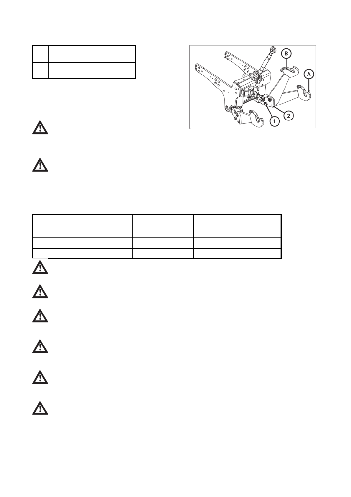
Working and transport position of the front three-point hitc
h
p
CONTROLS, INSTRUMENTS & OPERATIONS
72
A Working position of the front
three-point hitch
B Transport position of the front
three-point hitch
Changing the position of the draw-bars of the front threepoint hitch:
1. Release and remove the pin (1) from the opening.
2. Lift the arm from position (A) to position (B).
3. Lock the arm by inserting the pin (2) in the opening (2)
and secure the pin.
Only insert the pin in the openings, never check
PCLPN062
whether the opening is free with your fingers!
Driving with agricultural machines attached to the front three-point hitch
The maximum permissible speed of the tractor with agricultural machines attached to the front
three-point hitch is 15 km.h
-1
. If no implement or weight is attached to the front three-point hitch, we
recommend you to lift the lower lifting draw-bars to the transport position.
Towing equipment
Maximum permissible load of the hitch
Maximum draft force
Maximum permissible vertical
Hitch type
(dynamic load)
load
Lower hitch 29,4 kN 500 kg
Multi-level hitch attachment tail piece 42,8 kN 1,200 kg
Warning: All implements mounted on the tractor must be firmly attached and must be in
accordance with the implement manufacturer's instructions. Use only authorized devices.
Warning: The front towing hitch should be used for emergency trailer towing or for towing the
tractor in the yard or in an authorised service centre.
Caution: Never transport partially attached implements, trailers or agricultural machines by
attaching them to the upper link of the three-point hitch. This could cause the tractor to get stuck or
turned over.
Warning: When towing, always secure the hitch pin with a suitable safety pin with a safety clip
to prevent the hitch pin from being pulled out spontaneously. The safety pin must always be
attached to the hitch.
Warning: The maximum permissible hitch load (horizontal and vertical), the maximum
ermissible hitch height for road. Use and the maximum trailed load are indicated in the tractor
registration document.
Caution: Do not allow another person to ride on the drawbars or the lower links when the
tractor is in motion.

Lower hitc
h
n
CONTROLS, INSTRUMENTS & OPERATIONS
73
1 - Lock pi
2 - Pin
U18N050
Connection and disconnection of implements
To connect implements in the lower hitch, proceed as follows
- Remove the locking pin 1
- Remove the pin 2
- Slowly reverse the tractor up to the implement
- Insert pin 2
- Secure the locking pin 1
Multistage adjustable suspension
Serves for connecting double axle or lighter single-axle trailers. Guidance nozzle is vertically adjustable.
When working with various agricultural machines it is necessary to adjust the suspension vertically or
demount where necessary.
All hitch pins must always be secured with the appropriate pin protections.
1. Multi-Level Hitch Console
2. Rear PTO Cover
3. Multi-Level Hitch Attachment Tail Piece
4. Lower Hitch
Disassembly of the rear PTO cover
Pull the locking device (1) towards yourself to remove it.
Grasp the back of the cover and lift the cover in the
direction of the arrow into the vertical position.
Pull the cover upwards to remove it from the hooks (2).
Follow the reverse procedure to reassemble the cover.
When working with the rear PTO, the cover
must always be installed.
UCL18NN006
UCL18NN007

Lower hitch disassembl
y
A
y
.
CONTROLS, INSTRUMENTS & OPERATIONS
74
fter releasing the locking devices, remove the two pins
(1).
Remove the lower hitch by pulling it backwards in the
direction of the arrow.
Follow the reverse procedure to reassemble the lower
hitch.
UCL18NN009
Height adjustment and disassembly of the multi-level hitch attachment tail piece
Remove the rear PTO cover and, if necessary, the lower
hitch before handling the multi-level hitch attachment tail
piece.
Grasp the multi-level hitch attachment tail piece firmly.
Moving the lever (1) in the direction of the arrow (upwards)
engages the locking pins (2) and the tail piece is freely
movable in the grooves of the multi-level console.
Adjust the multi-level hitch attachment tail piece to
a suitable height so that the locking pins (2) are aligned
with the holes in the multi-level hitch console and release
the lever (1); the locking pins (2) slide into the holes in the
multi-level hitch console.
Check that the pins (2) slightly overlap the outer edge of
the multi-level console.
UCL18NN008
Perform the disassembly of the multi-level hitch
attachment tail piece after pulling the lever (1), by sliding
the tail piece upwards out of the grooves of the multi-level
console. Perform the assembl
in the reverse order
injury.
Never insert your fingers into the holes in the multi-level hitch console as there is a risk of

Starting the engine
.
CONTROLS, INSTRUMENTS & OPERATIONS
75
Before starting the engine, perform pre-operation check as
described in the chapter Safe Operation of Tractor.
(1) Sit into the driver's seat.
(2) Depress the foot brake.
(3) Move the hydraulic lever in the lower position.
(4) Move the gearshift lever to neutral.
(5) Insert the ignition key and turn it to the ON position.
(6) Check that all indicator lights are working.
(7) The operator must turn the key to the ON position. The
glowing circuit is automatically activated. The operator
must wait until the glowing indicator light switches off.
When it switches off, turn the key to the start position and
start the engine.
U18N049
(8) Check that the engine is running and all warning lights
are off
Important:
Never turn the key to the start position while the engine is running as this can cause serious damage
to the starter and engine flywheel.
Only engage the starter for a period of not more than 10 seconds.
If Engine does not start, rest the starter for about 20 seconds and try again for a maximum of 10
seconds.
If the engine does not start after repeated attempts, refer to the fault tracing guide.
Important: Especially in cold weather, always allow the tractor to idle for a while to warm up &
build up sufficient oil pressure to ensure normal operating temperature for longer engine life.
Stopping the engine
- After light work let the engine idle for a while and turn the key off.
Important: After long or heavy work allow the engine to idle for 5- 10 minutes and turn the key
off.
Warming up
When starting the engine allow it to warm up to operating temperature by allowing it to idle 5-10 minutes to
ensure full lubrication and operating temperature. Failure to do so can shorten engine life substantially.
Warming up in cold weather
Cold weather will change the viscosity of the oil, resulting in a reduced oil pumping capacity, which can
cause damage to the engine if it is not warmed up correctly. It also causes problems with the hydraulic
system and the synchromesh in the transmission.
Correct times for warming up are:
Temperature Time for warming up
Above 50°F 5~10 min.
50°F ~ 32°F 10~20 min.
32°F ~ 14°F 20~30 min.
14°F ~ -4°F 30~40 min.
Below - 4°F Over 40 min.
Running-in Period
Make sure to observe the following instructions for use in the first 50 hours of machine operation.
(1) Do not drive at excessive speed and do not overload the tractor.
(2) Only use the tractor's full power if the engine is sufficiently warmed up.
(3) Do not run the engine to maximum speed.
(4) Perform regular maintenance and change oil and fluid after 50 hours of use.
(5) To refill and replace engine oil, see Maintenance.

Sharp change of direction in the fiel
d
A
CONTROLS, INSTRUMENTS & OPERATIONS
76
llow the engine speed to return to idle, simultaneously
depress the clutch and apply the brakes.
When the tractor stops, lower the attached implement and
move the main transmission to the neutral position.
Apply the parking brake, stop the engine and remove the
ignition key.
U18NN050
Caution:Perform tight turns only at a slow safe speed. Doing so at a high speed can cause
rollovers and very serious injury or death.
Normal service braking and parking
Let the engine come back to idle and at the same time
push in the brake and brake simultaneously.
When the tractor has come to a halt, lower any implement
to the ground, and put the main gear in neutral. Apply the
park brake, stop the engine, and remove the key.
U18N053
Caution: Always apply the park brake when parking. Failure to do so can cause accidents and
damage. As an extra precaution when parking on a slope, chock the rear wheels.

Driving downhill
p
CONTROLS, INSTRUMENTS & OPERATIONS
77
Use the engine's ability to brake when traveling downhill.
Never rely on the brakes only and never travel downhill with the gears in neutral.
Caution: When operating in hilly terrain the risk of the rollover is increased substantially,
lease drive with extra care. When towing trailers in hilly terrain ensure that they are equipped with
brakes, use a lower gear to get maximum engine braking and do not change gears on a down hill run.
Operation of the diff lock
Although the differential lock is a very useful thing, caution is required when using it, as misuse can lead to
hazardous situations.
The differential lock should only be used in situations where one of the rear wheels loses traction.
Warning: Use low engine revolutions when using the diff lock. If the diff lock does not release
after removing the foot from the pedal use the left and right brake pedals in turn to release it. Do not
try to engage or use the diff lock on tight turns as serious damage can result.

Check during drivin
g
CONTROLS, INSTRUMENTS & OPERATIONS
78
Constantly observe the warning lights on the instrument panel and if any of them comes on, stop the tractor
to determine the cause.
Oil pressure light
If the oil pressure light comes on check the oil level first of
all.
If the oil level is OK ask a qualified dealer to check the
reason for the light coming on.
UCL18N044
Battery charging
If the alternator warning light comes on check all
connections and ensure that the fan belt is not broken.
If all connections and the fan belt are intact consult your
dealer to determine the cause of the problem.
Fuel gauge
To prevent excessive condensation in the fuel tank, refill
the fuel at the end of each day and ensure that the level
during the day does not fall to a level when the fuel
system needs to be bled after refueling.
UCL18N045
UCL18N046
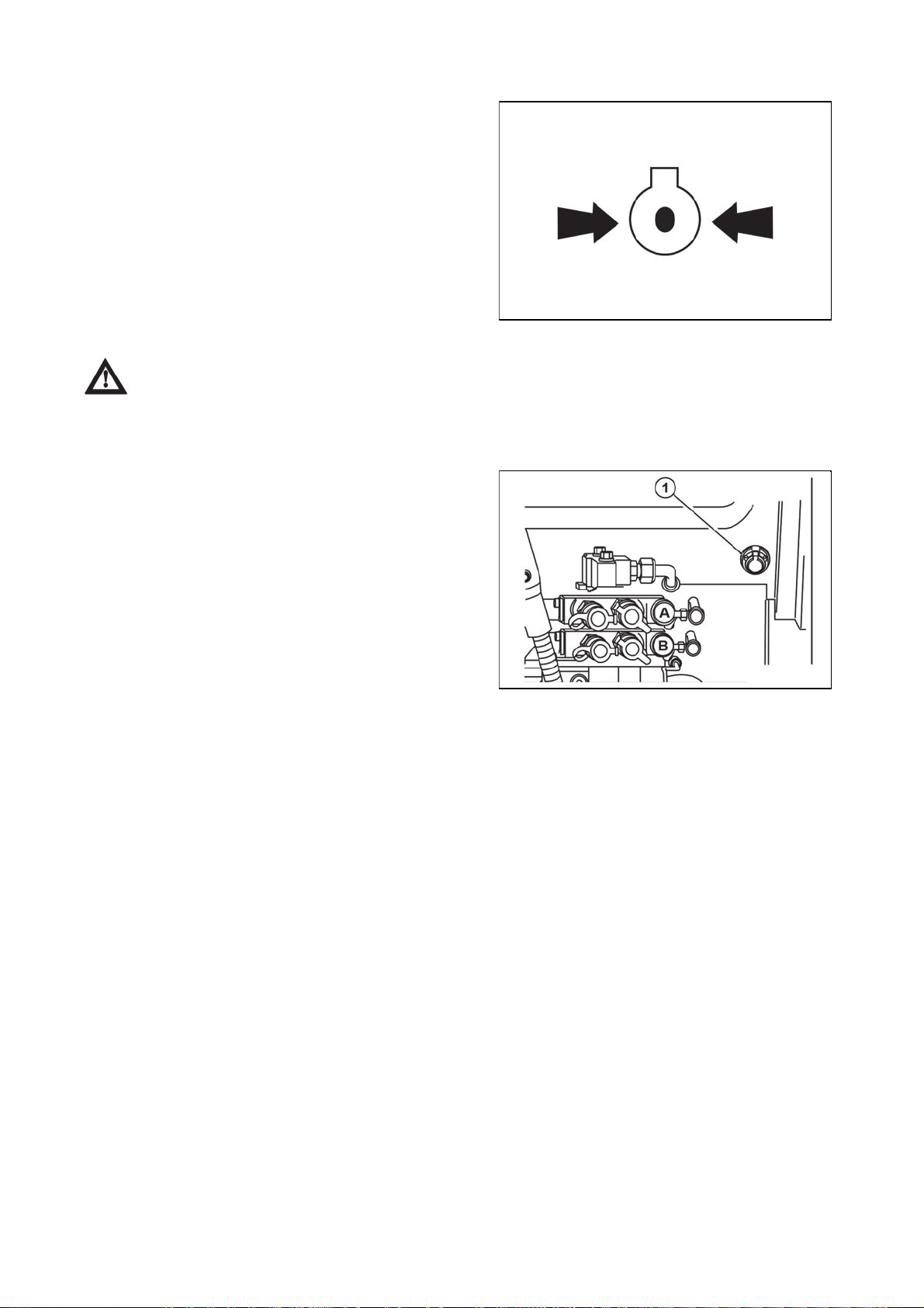
Engine cooling wate
r
t
CONTROLS, INSTRUMENTS & OPERATIONS
79
If the indicator indicates that the engine is overheating,
stop the tractor and check the radiator coolant level.
UCL18N047
Danger: Allow the engine to cool down before opening radiator cap as serious burns may
result due to hot steam & boiling water.
Also check that the radiator fins are not clogged or that the tractor fan belt is not broken or slipping.
Trailer socket (seven terminal electrical socket type)
1 - Trailer socke
To operate the electrical systems of implements, trailer
lighting, warning lamp etc.
UCL18N048

Treads
CONTROLS, INSTRUMENTS & OPERATIONS
80
Front and rear wheels can be set in two positions. This will change the tread.
A
Tire size
Standard tread
(mm)
Front 240/70 R16 1,330 1,427
R1
Rear 320/70 R24 1,264 1,172
Front 12-16,5 1,321 1,436
R4
Rear 17,5L-24 1,370 1,070
UCL18NN027
B
tread
(mm)

Changing the front wheel trea
d
CONTROLS, INSTRUMENTS & OPERATIONS
81
Secure the tractor against movement first, lift the axle with a jack and support it. Tighten the
front wheel bolts and nuts to the torque of 157 Nm.
The tread is changed by turning the wheel around and mounting the rim offset inwards, while swapping the
two front wheels to maintain the correct direction of the tire tread with the arrow forwards.
- Remove the front wheels.
- Swap the front wheels and mount with the rim offset inside.
- Tighten the front wheel bolts and nuts to 157 Nm.
- After driving 100 m with the unloaded tractor, retighten the front wheel bolts and nuts to the specified
torque.
- After loading the tractor, tighten the front wheel bolts and nuts after 3 hours of operation to the specified
torque.
- After 10 hours of operation, recheck the tightening of the front wheel bolts and nuts.
Changing the rear wheel tread
Secure the tractor against movement first, lift the axle with a jack and support it. Tighten the
rear wheel bolts and nuts to the torque of 363 Nm. The tread is changed by turning the wheel around and
mounting the rim offset inwards, while swapping the two back wheels to maintain the correct direction of the
tire tread with the arrow forwards.
- Remove the rear wheels.
- Swap the rear wheels and mount with the rim offset inside.
- Tighten the rear wheel bolts and nuts to 363 Nm.
- After driving 100 m with the unloaded tractor, retighten the rear wheel bolts and nuts to the specified torque.
- After loading the tractor, tighten the rear wheel bolts and nuts after 3 hours of operation to the specified
torque.
- After 10 hours of operation, recheck the tightening of the rear wheel bolts and nuts.
Front drive axle fenders
UCL18NN025
There are two versions of the front fenders
A - Front fenders for 12-16,5 wheels
They are on adjustable brackets that can be adjusted vertically after loosening the screws and nuts (1) and
laterally after loosening the screws and nuts (2) according to the values in figure (A).
B - Front fenders for 240/70 R16 wheels
They are on adjustable brackets that can be adjusted vertically after loosening the screws and nuts (1)
according to the values in figure (B).
If the front fender brackets settings are changed, check the wheel stop setting on the front-
wheel drive axle.

Setting wheel stops with front drive axle
CONTROLS, INSTRUMENTS & OPERATIONS
82
Wheel stops with front drive axle must be set so that there
would be a distance of at least 50 mm between front drive
axle tires and tractor with full lock and full axle swing
around central pin.
Setting wheel stops with front drive axle check
1. Set full lock to one side and check that the distance
between a tire and the nearest solid point on the tractor is
at least 50 mm. Check both front tires.
2. Turn the steering to full lock to the other side and check
according to point 1.
3. Heave one side of the front axle to the maximum swing
(front axle leans against the bracket) and check according
to point 1 and 2.
4. Hoist the other side of front axle to the maximum swing
(front axle leans against the bracket) and check according
to point 1 and 2.
The setting of stops (A) changes after the release of a nut
(2) and unscrewing or screwing in a screw (1).
After the change in setting wheel stops with
front drive axle, it is always necessary to check their
setting according to points 1 to 4.
ucl18nn026
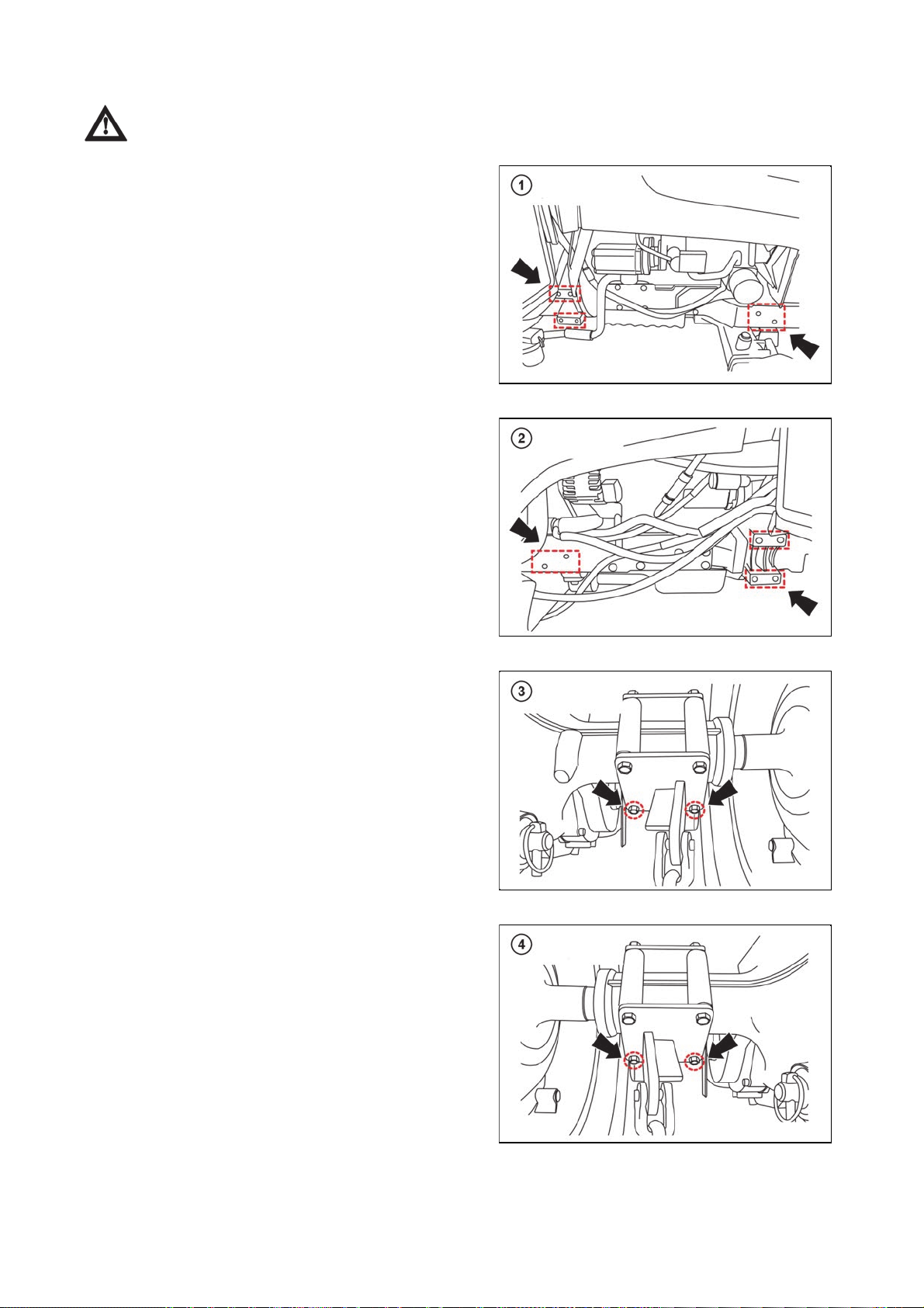
Front loader mounting points
CONTROLS, INSTRUMENTS & OPERATIONS
83
For detailed information on the assembly and operation of the front loader, refer to the
documentation supplied with your specific front loader.
1 - Right (front)
2 - Left (front)
UCL18N050
3 - Right (rear)
4 - Left (rear)
UCL18N051
UCL18N052
UCL18N053

NOTES
84

Check and service
.
t
MAINTENANCE INSTRUCTIONS
85
This section gives full details of the service procedures necessary to maintain your tractor at peak efficiency
while the lubrication and maintenance chart provides a ready reference to these requirements
Service inspections
Service inspections are performed as follows:
The first service inspection at the state of the engine hour counter of 50 EH maximum, but not later than
6 months after commissioning of the tractor. The second service inspection after covering another 200 EH
(at the state of the engine hour counter of 250 EH maximum) but not later than 12 months after the first
service inspection. Next service inspections always after covering another 250 EH but not later than 12
months after the previous service inspection. The service inspections are a part of tractor maintenance. The
services authorized by Zetor will provide professional performance of service inspections according to the
manufacturer's instructions.
Pre-start checks
To avoid problems it is recommended that a range of checks be carried out daily before starting the tractor.
For full details of the items and frequency please refer to the following tables - Periodical check and service
tables.
Engine coolant
Remove the radiator cap and make sure that the coolant
reaches up to the filler neck and that it is clean. Check tha
the correct antifreeze or anti-corrosion mixture is used.
1 - Radiator Cap
2 - Expansion Vessel
If corrosion of the cooling system is noticeable in the
coolant color, completely drain the system and fill with the
correct mixture of water and antifreeze or corrosion
inhibitor.
1 - Drain Valve
UCL18N054
UCL18N055
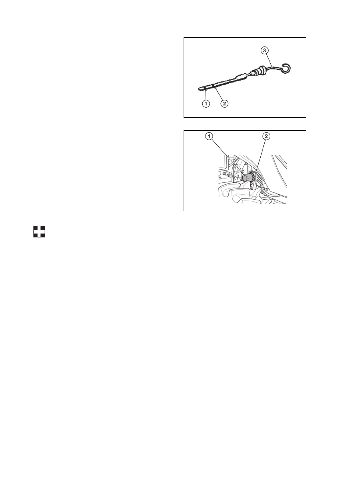
Engine oil
MAINTENANCE INSTRUCTIONS
86
1 - Minimum Level Mark
2 - Maximum Level Mark
3 - Engine Oil Dipstick
Remove the dipstick, wipe it and immerse in the oil pan.
Make sure the oil level is between the upper and lower
mark, near the upper mark. If the oil level is too low, add
more oil. Never exceed the replacement interval.
Always check the oil before starting the engine or at least
after 30 minutes after stopping the machine. Never check
the oil level when the engine is running or immediately
after it has been stopped.
1 - Engine oil filter
2 - Engine Oil Dipstick
UCL18N056
Important: Do not overfill the crankcase with oil.
U18N059
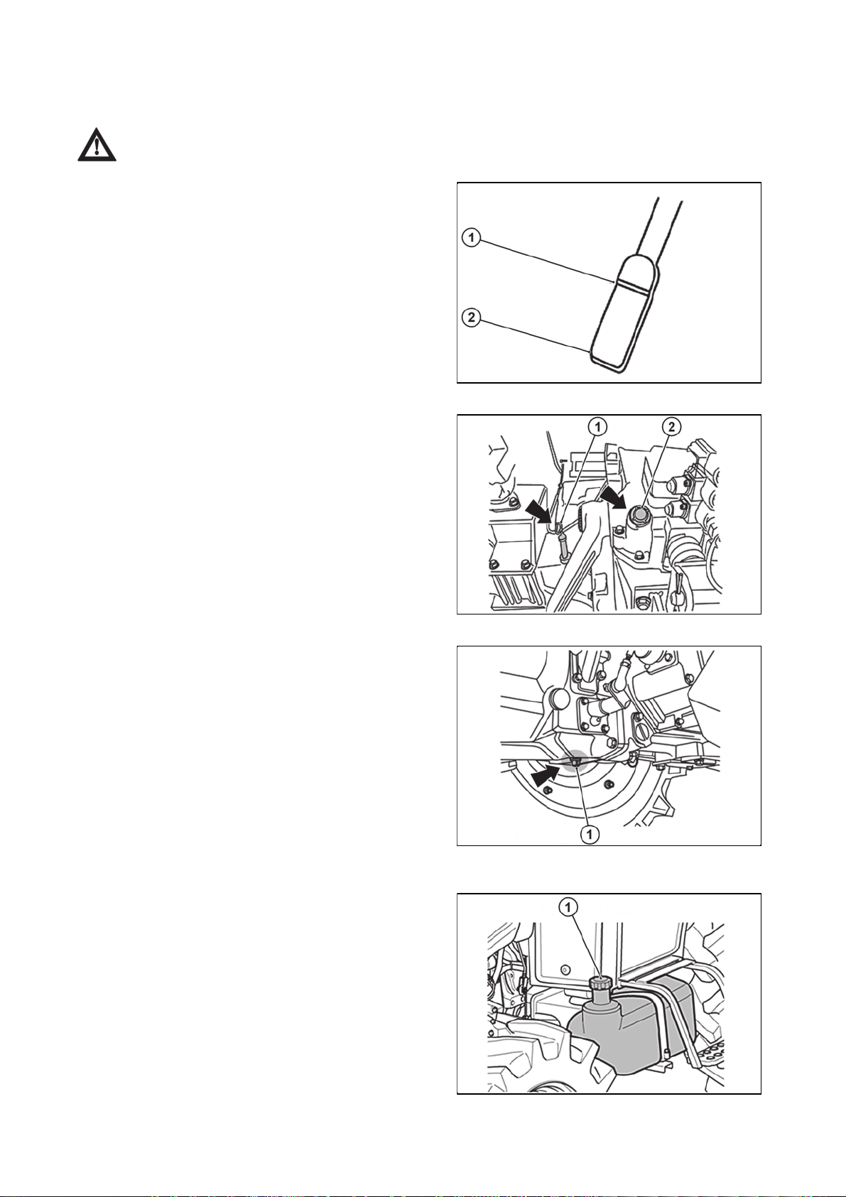
Transmission oil
MAINTENANCE INSTRUCTIONS
87
Check the level using the dipstick at the top of the transaxle.
If the level is low, add more oil through the filler.
Caution: Always ensure that you use the correct oil for topping up or oil changes.
1 - Maximum Level
2 - Minimum Level
1 - Oil dipstick
2 - Filler
U18N061
1 - Drain plug
Fuel
1 - Fuel Tank
Look at the fuel gauge to check the fuel level and refill if it
is too low.
It is good to refill the tank after using the tractor to avoid
condensation of water in the tank.
U18N062
U18N063
U18N064

Tyre pressure
MAINTENANCE INSTRUCTIONS
88
The air pressure used in the tires has a direct bearing on the life of the tire and its performance in the field.
Ensure that the tire pressures are correct and in accordance with the table in chapter Track adjustment.
To make a visual judgment see the drawing on the right.
1 - Excessive
2 - Correct
3 - Insufficient
U18N065
Tire size and inflation pressure
Tire sizes and combinations available from Zetor.
Air pressure
Tire size Rim size
(bar)
Front 240/70 R16 W8x16 2.4
R1
Rear 320/70 R24 W11x24 1.6
Front 12-16,5 W9, 75x16,5 4.5
R4
Rear 17,5L-24 W15Lx24 2.7
The air pressure values in the table are indicative, the tire pressure values given by the tire
manufacturer are preferred.
Important: It is strongly recommended that the tire pressure is checked with the correct gauge,
as well as a visual check of the pressure before starting to drive.
Danger: Excessive tire pressure can cause excessive tire wear, poor manoeuvreability and
accident!
Tire inflation
If the tractor is equipped with air brakes for trailers and
semi-trailers, the tractor air pressure system can be used
to inflate the tires.
Remove the cap (1) on the left compressed-air tank
(accessible from the rear of the tractor) and screw the tire
inflation hose onto the fitting (2).
Inflate the tires while the engine is running and the tractor
is secured against movement by using the hand brake, if
necessary by wedging the wheels.
When tire inflation is complete, remove the tire inflation
hose and attach the cap (1) to the fitting (2).
UCL18NN024

Steerin
g
MAINTENANCE INSTRUCTIONS
89
Check the steering wheel for excessive play.
Brake
Check that both the left and right brakes are correctly adjusted and functioning at the same time. The correct
play of the brake is 30 ~ 40 mm.
Electrical installation
Check of state and function of electrical equipment and accessory.
Installation of the Front Loader
Follow the instructions supplied with the loader to connect and disconnect the loader.
1 - Loader and Front Three-Point Hitch Distributor
2 - Transmission Oil Filter
U18N066

Maintenance and adjustment schedule
MAINTENANCE INSTRUCTIONS
90
Periodical check and service table
O Check, refill, modify or clean
XX First Replacement
X Replace
Service interval (operating hours,
indicate)
Group Item Daily
Engine oil and
filter
Air cleaner
(engine + air
brake
compressor, if
fitted)
Refrigerant in
the radiator
Engine
O xx x x
O
5
0
1
1
2
2
3
3
4
4
0
5
0
5
0
5
0
5
0
0
0
0
0
0
0
0
O O x O O x
Frequency Comment
5
0
0
First change
after 50 hours
or 6 months,
then every
250 hours and
12 months.
Clean every
100 hours
Check daily,
refill if
necessary,
change every
24 months
Check daily
Radiator O
Fuel O Refill tank
Fuel cleaner O xx O O O O x
Fan belt O Check daily
Battery O O O O O Check daily
Loose nuts
and bolts
Radiator hose
connections
Caution: These intervals are for operation under normal conditions and need to be reviewed
under severe conditions to a greater frequency.
O Check daily Tighten
O Check daily
for damage
and leaks
Tighten, if
necessary

Group Item Daily
MAINTENANCE INSTRUCTIONS
91
Transmission
oil
O xx x
Service interval (operating
hours, indicate)
1
1
2
2
3
5
0
0
0
5
0
0
0
5
0
0
0
3
5
0
4
0
0
4
5
0
Frequency Comment
5
0
0
First
change
after 50
hours or
6 months,
then every
500 hours
and 12
months.
Chassis
Clutch pedal
clearance
Brake pedal
clearance
Condition of
both brake
pedals
Individual lever
functions
Steering wheel
clearance
Convergence O O
Lubricant in
front wheel hub
Hydrostatic
steering check
O Check daily (20~30 mm)
O Check daily (30~40 mm)
O Check daily
O Check daily
O Check daily
O O
O O
Check
every 250
hours
Lubricate
every 250
hours
Adjust so that
both work
simultaneously
and brake
simultaneously
Operation and
function
Approx. 50 mm
on the steering
wheel
circumference
(2~6 mm)

Group
MAINTENANCE INSTRUCTIONS
92
Item Daily
Servisní interval (provozní hodiny,
vyznačte)
1
1
2
2
3
3
5
0
0
0
5
0
0
0
5
0
0
0
5
0
4
0
0
4
5
0
Frequency Comment
5
0
0
Chassis
Check the
wheel nuts for
tightness
Instruments
and indicator
lights
Lubricant for
each
lubrication
point
Loose bolts
and nuts
Hydraulic oil
filter
Hydrostatic
transmission
oil filter
Front 4WD
axle oil
O Check daily
O Check daily
Add every
50 hours (in
O O O O O O O O O O
O Check daily
xx x
xx x
xx O O O O x
dusty
conditions
daily)
Change
every 500
hours
Change
every 500
hours
Check every
100 hours
Change
every 500
hours
Tighten, if free
Front: 157Nm
Rear: 363Nm
Tighten to the
correct
moment.
Refill, if
leaking.
Check
electrical
wiring
Accelerator
pedal
adjustment
Hydraulic
pipes and
hoses
O O
O O
O
Check every
year
Check every
250 hours
No loose or
damaged
terminals,
damaged or
missing wiring.
Proper
connection.

Diagram of filling points and lubrication points
3
MAINTENANCE INSTRUCTIONS
93
1 - Oil Filler
2 - Lubrication Point
3 - Drain Plug
4 - Sight Gauge
5 - Grease Nipple
6 - Engine Oil Filler Neck
7 - Front-Wheel Axle Oil Drain Plug
8 - Front Axle Lubrication Point
9 - Front-Wheel Axle Oil Filler
10 - Radiator
11 - Engine Oil Drain Plug
12 - Transmission Oil Drain Plug
- Transmission Oil Filler
1
U18N067

Fuels, coolants and lubricants used - amounts
plying
MAINTENANCE INSTRUCTIONS
94
No. Filling point Fillings Quantity Liter (gal.)
MODEL UTILIX HT45/ HT55
1 RADIATOR
50/50 : Ethylene Glycol/Water (L.L.C)
ASTM D4985 / D6210
8.5 l (2.24 US gal)
API : CH4 grades
2 ENGINE
Recommended SAE viscosity grades
8.2 l (2.16 gal)
A: Viscosity
B: Temperature
3 TRANSMISSION CASE (API GL-4 Grades)Gear oil #80 or #90 35 l (9.24 US gal)
4 FRONT AXLE (API GL-4 Grades)Gear oil #80 or #90
10 l (2.64 US gal)
5 FINAL DRIVE CASE(B) (API GL-4 Grades) Gear oil #80 or #90
6 BALL JOINT Grease As required
7 FUEL TANK Diesel fuel 60 l (15.85 US gal)
The manufacturer does not take responsibility for any damages caused by the usage of
service fillings that do not comply with requirements stated in this service manual.
Recommended SAE viscosity grades for engine oil
A - Viscosity
B - Temperature
U18N068
ZETOR service fillings
To maintain best operational characteristics of your tractor, original operational Zetor fillings are
recommended to be used.
Motor oils
Engine oil Zetor 10W-40 L-SAPS
Oil in the gearbox and final drivehousing
Oil for gearing mechanisms of tractors ZETOR EXTRA 10W30 STOU
Oil for the front driving axle
Oil for the front axle ZETOR LS 80W
Other recommended service fillings tested on Zetor tractors
Oil to gear systems of tractors
1 - RPM Tractor Hydraulic Fluid or Textron TDH Premium (CALTEX)
2 - TDH Oil or TDH Oil special (TEXACO)
3 - Chevron 1 000THF (CHEVRON)
Fuel
Diesel oil com
with the regulation of EN 590
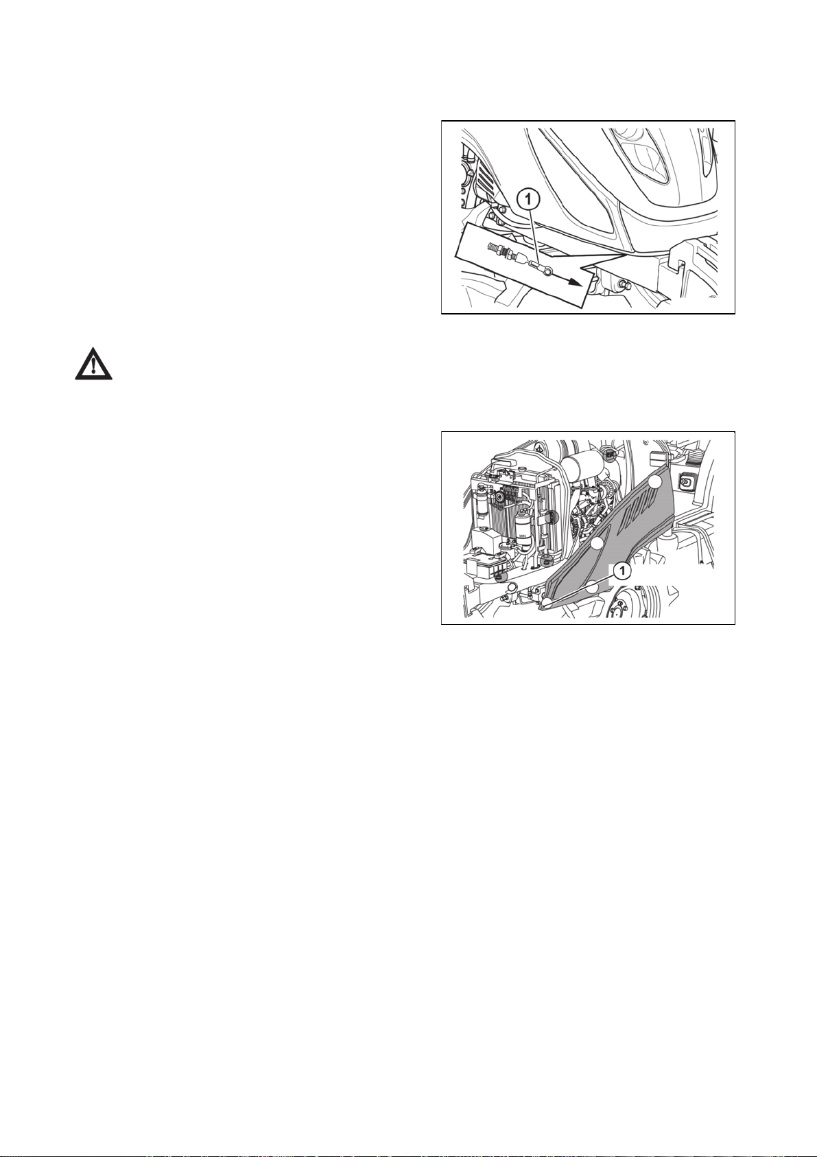
Procedure to open the front hoo
d
MAINTENANCE INSTRUCTIONS
95
Front bonnet opening
To open the hood:
Unlock the hood by pulling the handle (1) in the direction
of the arrow (forward).
The handle is located under the right front corner of the
hood.
Grasp the hood and lift it.
In the raised position, the hood is locked by the gas-liquid
safety stops.
To close the hood:
Check that the handle (1) has returned to the rear
position.
Pull the hood down and snap it down until the hood lock
engages.
When the front hood is slammed shut, the headlight bulbs located in the front hood may be
damaged.
Opening the side cover
1 - Support Pin (1)
To open it, grasp the side panel of the hood and pull the
front panel upward to separate it from the guiding support
pin (1). Then pull the hood side panel forward.
UCL18NN011
UCL18N061

Fuel syste
m
MAINTENANCE INSTRUCTIONS
96
Use clean diesel fuel only.
Important: As diesel fuel equipment is susceptible to contamination by dust or water, ensure
that all dust and water is kept well away from the fuel tank.
U18N072
1 - Fine Fuel Filter (B)
2 - Fuel Return Line
3 - Engine
4 - Injection Pump
5 - Bleed Screw
6 - Fuel Supply Line
7 - Transport Pump
8 - Coarse Fuel Filter (A)
9 - Fuel Tank
Bleeding the fuel system
1. Fill the tank with fuel and turn the ignition key to on.
2. Loosen the fuel pipe nut of the Injection pump two or three turns.
3. When fuel free from air flows (bubbles) from the fuel pipe nut, tighten the fuel pipe nut.
4. The bleeding of the system is now finished.
1- Fuel Cleaner
2 - Transport Pump
U18N073

Changing oil in tracto
r
A
g
MAINTENANCE INSTRUCTIONS
97
Always use quality oils as engine or transmission oil (refer to the chapter: Recommended transmission oil)
Refer to the tables 'Periodical check and service table' for the change frequency.
Changing engine oil
The grade of oil to be used will depend on the ambient temperature.
The tractor is shipped from the factory with 15W/40.
z For summer use over 77°F (25°C) use SAE 30.
z For temperatures from 32°F~77°F (0°C~25°C) use SAE20 or 15W/40.
z For temperatures below 32°F (0°C) use SAE 10W.
Important:
When changing the oil, replace the filter at the same time.
lways use the same oil, as using different types of oils or oils with different specifications can
cause damage.
Dispose of the old oil according to valid legal regulations.
1 - Engine oil filter
2 - Level gauge
1 - Engine oil drain plu
UCL18N063
U18N060

Draining oil from engine
g
MAINTENANCE INSTRUCTIONS
98
1. unscrew the drain plugs, best immediately after terminating the drive or after heating the engine to working
temperature
2. drain oil
3. clean the drain plugs
4. screw the drain plugs back in
Engine oil filter
Using the oil filter wrench, screw the filter anticlockwise to remove it. Lightly lubricate the rubber seal ring on
the new filter with oil, rotate clockwise until the seal reaches the sealing surface, and then rotate another 2/3
turn to tighten it properly.
Pouring oil to engine
Pour the set amount of motor oil engine by filling hole, start the engine and allow it to run for 2 - 3 minutes
with engine revolutions of 750 - 800.
After stopping the engine and settling the level recheck the amount of oil with a dipstick and check the
htness of filter, drain plugs and other joints.
ti
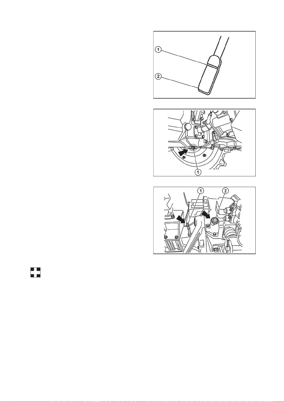
Changing the transmission oil
MAINTENANCE INSTRUCTIONS
99
1 - Maximum Level
2 - Minimum Level
Remove the drain plug from the bottom of the
transmission and drain the oil.
Return the drain plug and check for tightening and
leakage.
1 - Transmission oil drain Plug
U18N075
U18N076
1 - Dipstick
2 - Filler
Fill the transmission with new oil not exceeding the
maximum level marked on the dipstick.
z Capacity 35 l (9.24 US Gal)
U18N077
Important: Always use the same type of oil. Using another type of oil or oil with different
specifications may damage the transmission. Dispose of the old oil according to valid legal
regulations.
 Loading...