


3
ZETOR
This Operator’s Manual will help you to become familiar with the operation and maintenance of your new tractor.
In spite of the fact that many of you have reach experiences with operation of various tractors, please, read carefully
all safety rules, operating instructions and the other information in this Operator’s Manual.
You will find a lot of new information and receive a perfect overview how to use the tractor with the highest
efficiency at various operations.
Your new tractor will be your reliable and long-time friend if observing the mentioned safety rules, tractor
maintenance and safe operation.
The manufacturer of your tractor wishes you thousands of satisfactorily worked hours
ZETOR
Brno

4
Information about technical specifications, design, equipment, material, and external appearance is valid at the time of printing
this Operator’s Manual. The manufacturer reserves the right to make changes.

5
CONTENTS
The “Operator’s Manual” contains
descriptions, operation and maintenance
of standard and optional tractor
equipment, which are allowed to be
installed on a tractor. The option that is
not a part of standard tractor equipment
installed by the manufacturer cannot be
a subject of a claim. The tractor “Service
Coupon Booklet” is not a part of the
Operator’s Manual. This is a separate
booklet that is passed to you when you
purchase a new tractor.
Page
Location of serial numbers .......................................................................................... 7
Safety precautions for users........................................................................................ 9
Preventive daily maintenance ...................................................................................13
Acquaintance with tractor.......................................................................................... 21
Tractor operation....................................................................................................... 51
Tractor running-inn.................................................................................................... 69
Transportation use .................................................................................................... 75
PTO drive of agriculture machines ............................................................................ 85
Hydraulic system....................................................................................................... 93
Hitches .................................................................................................................... 107
Wheel tread change ................................................................................................ 117
Ballast weights ........................................................................................................ 125
Electrical system ..................................................................................................... 133
Tractor maintenance ...............................................................................................145
Maintenance instructions ........................................................................................ 165
Adjustment .............................................................................................................. 185
Main specifications.................................................................................................. 199
Index .......................................................................................................................217

6
TRACTORS Z 8541 - Z 10541
TRACTORS WITH FRONT DRIVING
AXLE (4 X 4):
Tractor type Engine output
(kW)
Z 8541 60
Z 9541 66
Z 10541 74
E1

7
LOCATION OF SERIAL NUMBERS
E2
Tractor type plate Engine serial No
Tractor serial No
Cab serial No

8
LOCATION OF SERIAL NUMBERS
When ordering the spare parts and when being in contact, no matter if written or oral, remember to use the data on your tractor,
which you can put down into the frames below.
Tractor model
Zetor 8541
Zetor 9541
Zetor 10541
The “left“, “right“, “front“ and “rear“ side
of the tractor hold so in the driving
direction.
The manufacturer reserves the right to
make changes in design and equipment
leading to improvements of tractor
features.
Tractor serial number
Engine serial number
E3

9
SAFETY PRECAUTIONS FOR USERS
Pay particular attention to articles in
Operator’s Manual that are marked
with these symbols.
You will find this symbol at all
important warnings regarding
safety of tractor operation.
Heed these warnings and be
very careful in these cases!
Inform your co-operators and
other users about these
warnings.
Study carefully chapters marked
with this symbol before starting
operation, service or adjustment
of the tractor.
You will find this symbol
whenever important information
on operation, adjustment and repairs of starter motor appears.
Heed these warnings and be
very careful in these cases!
This symbol refers to chapters in
Operator’s Manual dealing with
environmental protection.
GENERAL SAFETY REGULATIONS
1. Only a trained operator having a valid
driving license and being properly
acquainted with operating and safety
rules can operate the tractor.
2. Except for safety warnings mentioned
in this Operator’s Manual you must
respect all general safety and traffic
regulations of the country, in which the
tractor is in operation.
PROPER CLOTHING
3. Do not wear loose clothing and tie
long hair back behind your head.
4. Use suitable (prescribed) personal
protection means (working shoes,
gloves, etc.) at work.
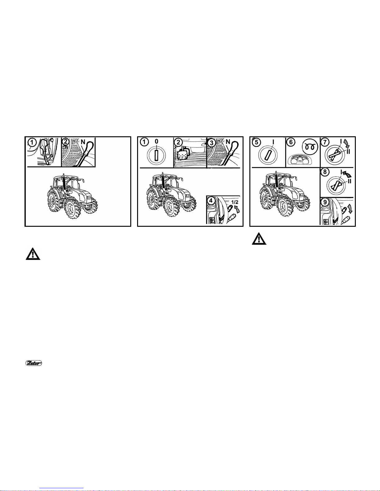
STARTING THE ENGINE
5. It is not allowed to start the engine
when driving downhill.
6. Starting the tractor by means of towing
using another tractor or vehicle is
allowed only when the pull bar is used.
7. Start the tractor from the driver’s seat
only with the gearshift lever in
neutral and with the clutch pedal
depressed. Life hazard when
starting by means of the starter
connector short circuit.
8. The ignition key must be in position "I".
9. When preheating engine by electrical
heater, plug the heater first and
connect the cable into electricity after.
On termination of preheating,
disconnect the cable from electricity
first.
OPERATION
10. Hoses of hydrostatic steering, brakes
and fuel system must be checked
and replaced in case of any damage
indication. The signs of damage may
be for example: cracks on hose
surface, loosening of hose fittings (it
is possible to verify it easy by pulling
the hose from fitting) and mechanical
damage to hose. It is necessary to
replace the hoses with marked
service life immediately after
expiration of the marked service life.
11. Brake pedals must be latched with
trailers and implements when driving
on the road.
12. Brakes and steering must be
permanently in perfect condition.
13. Driving downhill without gear shifted
is forbidden!
14. Pay special attention when driving in
hilly, muddy, sandy, icy and uneven
terrain.
15. Do not exceed the maximum
specified angle of inclination, that
should be 12° as a maximum

10
SAFETY PRECAUTIONS FOR USERS
16. Do not exceed the maximum
combination weight mentioned on
the tractor type plate or on the rear
fender.
17. Do not use the differential lock when
driving in a curve.
18. It is forbidden to get in / out when the
tractor is moving.
19. Reduce the travelling speed to
15 km.h
-1
when driving with
agricultural implements hitched in
the front three-point hitch.
20. The front axle load must not fall
below 18 to 20 % of the
instantaneous combination weight
when agricultural implements hitched
in rear hitches are used.
TRANSPORTATION OF PERSONS,
OPERATION
21. Number of persons transported by
tractor must not exceed the number
mentioned in the tractor registration
document.
22. Persons, that are not authorized to
work with the attached implement,
must not stand between tractor and
hitched implement (machine).
23. Make sure neither any person nor
any obstacle allows driving before
starting tractor move.
24. Maximum allowed travelling speed of
the tractor and trailer (or semi-trailer)
combination equipped with air brakes
is 30 km.h-1. Only tractor models
equipped with braked front driving
axle can move with the maximum
allowed speed (tractor and trailer or
semi-trailer) of 40 km.h
-1
.
TRACTOR RESCUE, TOWING
25. To recover the bogged-down tractor,
use the tow bar or cable.
Never use chains! Danger of life
in case of the chain rupture!
26. It is life dangerous to stand near the
tow rope when recovering the
tractor.
27. Front hook assembled on front
tractor frame serves for pulling of the
tractor alone only, i.e. without trailer
or another implement.
28. Never use free wooden blocks or
bars being put between tractor and
pushed subject when pushing other
vehicles (trailers, implements etc.).
LEAVING THE TRACTOR
29. Do not park the tractor with attached
implement in lifted position.
30. Do not forget to set the tractor
parking brake (shift the gear and
move the reversing lever to forward
drive position), remove the ignition
key and lock the cab before leaving
the tractor.
31. Usually use the left-hand side tractor
door when leaving the tractor. Look
round whether any vehicle is coming,
that could jeopardize your safety
when getting out of the tractor.
32. Use steps and handles when leaving
the tractor. Pay attention to a space
of the gearshift lever and hand fuel
delivery throttle control lever.
33. Set the tractor parking brake before
leaving the tractor with running
engine.
WITH THE STOPPED ENGINE ONLY
34. All activities connected with refuel-
ling, cleaning, lubricating and
adjusting the tractor or attached
implement can be done with the
engine at standstill and stopped
moving tractor parts only, except for
brake, hydraulics and charging
function check.
35. It is always necessary to shut the
engine off before removal of hood.
The engine can run in an enclosed
building or room only when sufficient
ventilation is secured. Exhaust gases
are harmful to your health.
PRINCIPLES OF FIRE PREVENTION
36. Refuel the tractor with the engine off.
37. Do not refuel the fuel tank up to the
top in summer season. Wipe the fuel
immediately when spilled.
38. Do not refuel the tractor nearby open
flame and do not smoke.

11
SAFETY PRECAUTIONS FOR USERS
39. Do not smoke and do not use open
flame when checking the battery
electrolyte level. Keep properly the
fire prevention regulations in areas
with increased fire hazard (hay-lofts,
straw-stocks etc.).
40. If the tractor is equipped with a fire
extinguisher, keep it always ready for
use.
HEALTH AND
ENVIRONMENTAL
PROTECTION
41. Tractors are not furnished with
special filters of air that is sucked to the
cab. Therefore the tractors are not
intended for work with aerosols and
other substances harmful to health.
Kerosene, diesel fuel, mineral oils and
other products from crude oil used for
operation and maintenance of tractor
may cause an injury in case of direct
contact with skin and it can irritate
mucous membranes, eyes, digestive or
respiratory organs. Some of them can
cause poisoning when swallowed.
42. The operators who come in contact
with oil products are obliged to heed
strictly safety and hygienic
instructions, make use of appropriate
protecting means, and work in wellventilated areas.
CRUDE OIL PRODUCTS
HANDLING
43. On termination of work or prior to
start eating, wash yourself with a
non-irritant agent and treat your
hands with a suitable skin ointment
or cream.
44. When connecting and disconnecting
the quick couplings of hydraulic
circuit, remove – with a piece of any
cloth – the residual oil, which
remains in the coupling socket or
possibly on the plug.
WASTE DISPOSAL
45. When disposing of the tractor or
some of its parts (including the
service liquids), as soon as their
service life is over, everybody is
obliged to proceed in accordance
with the provisions of the relevant
acts and regulations being in force in
a country, in which the tractor is
operated. The last tractor seller is
obliged – under the Waste Disposal
Act – to inform the consumer – when
selling the tractor – on the ways of
taking back some of the consumed
parts of the tractor. In question are
the oils and other service liquids,
storage batteries, and tires. These
components must be accepted back
from the consumer free of charge.
PREVENTIVE DAILY MAINTENANCE
46. Carry it out daily or after 8 to 10
working hours at latest.
SAFETY CAB
47. If corrosion, crash or other accident
cause damage to the protective
frame of safety cab, it is necessary to
replace the cab.
AIR-CONDITIONING
48. In any case it is not allowed to
disassemble, turn or otherwise
manipulate the screw joints of the airconditioning system, because
sudden leak of the coolant and quick
local cooling may occur. Contact or
freezing of components in your
hands may result in serious injury of
some tissues.
49. The air-conditioning system is
equipped with quick couplings, which
allow separation of the cab from the
tractor body if necessary, without any
leak of the coolant. Entrust the
interventions into the air conditioning
system to the service specialists.

12
SAFETY PRECAUTIONS FOR USERS
ELECTRICAL INSTALLATION
50. No additional interventions
into the tractor electrical
equipment (connection of
other electrical appliances)
are allowed because of its
possible overloading!
51. The values of electrical installation
are:
Nominal voltage 12 V =
Earthed pole ( - ) pole
Using of starting trucks or starting aid
devices with different voltage or
polarity may cause serious failures to
tractor.
52. It is necessary to be careful when
handling the battery and to avoid
short circuits. Tractors are equipped
with a battery cut-off switch;
remember to turn it off when handling
the battery.
53. Tractors must not be run with the
disconnected battery because
serious failure of tractor could occur.

13
PREVENTIVE DAILY MAINTENANCE
Carry it out daily or after every 8 - 10 engine working hours at the latest
E4

14
PREVENTIVE DAILY MAINTENANCE
E5 E6 E7
FUEL SYSTEM LEAKAGE
Check the fuel system for leakage
including the drain plug of the fuel tank.
Repair any leaks immediately.
ENGINE OIL LEVEL
The oil dipstick is situated on the righthand side of the engine. Having
unscrewed and removed the oil dipstick
check the engine oil level and check
connections of engine lubrication system
for leaks. Maintain the oil level between
the dipstick marks.
COOLING SYSTEM
Check connections of engine cooling
system for leaks and coolant level in the
expansion tank. The expansion tank is
accessible after removing the right-hand
side part of the hood. Add the missing
coolant up to the upper MAX mark. The
minimum permissible coolant level is
marked with MIN mark.
Loosen the overpressure filler
cap only after cooling down of
coolant. Danger of scalding!

15
PREVENTIVE DAILY MAINTENANCE
E8 E9 E10
FLUID BRAKES
Check fluid brakes and clutch fluid
control for leaks and check the brake
fluid level in the expansion tank. The
expansion tank is accessible after
removal of the left-hand side part of the
hood.
Keep the brake fluid level within 3/4
volume of the vessel (maximum level) up
to 1/2 vessel volume (minimum level).
Keep absolute cleanness when
handling the brake fluid. Check
the brake fluid level daily before
the tractor operation.
TRAILER AIR BRAKES
Check the air brake system for leaks and
check the air brakes of tractor and trailer
for efficiency.
TRAILER HYDRAULIC BRAKES
Check the hydraulic brake system for
leaks and check the hydraulic brakes of
tractor and trailer for efficiency.
HYDROSTATIC STEERING
Check the oil level in the hydrostatic
steering oil tank with dipstick. The
hydrostatic steering oil tank is accessible
after removing the left-hand side part of
the hood. In case of need add the oil up
to the mark on the dipstick, which
determines a correct oil level.
Check all hoses of hydrostatic steering
circuit for damage and oil leaks.
Check bolts and nuts of steering rods
and arms whether they are tightened
properly.

16
PREVENTIVE DAILY MAINTENANCE
E11 E12 E13
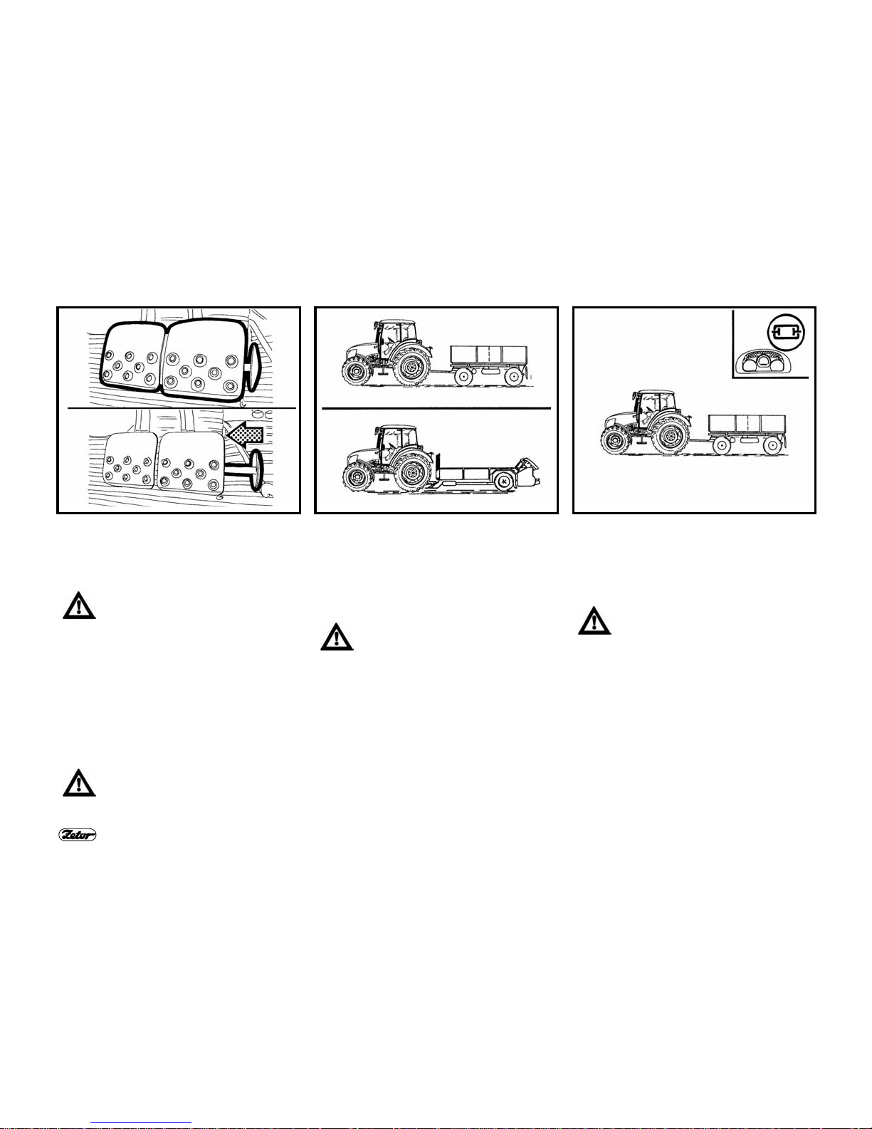
TIRES AND WHEELS
Check the inflation air pressures of front
and rear tires. Inflate them up to the
recommended pressures according to
operating conditions. Check, eventually
retighten bolts of front and rear wheels
(connections rim / disc and disc / wheel
shaft).
Never drive the tractor with
loosened wheel bolts!
AIR CLEANER
After signalling of the clogging indicator it
is necessary to perform maintenance of
the cleaner.
The indicator is accessible after
removing of the left-hand side part of the
tractor hood. It is situated near the
suction pipe elbow.
Clogging is mechanically indicated by
the red field that appears after clogging
of the filtration elements directly on the
clogging indicator.
A
cleaner is not clogged
B
cleaner is clogged, perform
maintenance
see chapter Maintenance
instructions
CAB FILTRATION
Check and eventually clean cab filters
located under the roof in front part.
Filter replacement interval depends upon
dustiness of working condition.
The partial regeneration of filters can be
done by shaking-out or blowing by the
pressurized air.
Cleaning or replacement of filter
elements can be performed after
removal of grills located in front of the
cab roof.

17
PREVENTIVE DAILY MAINTENANCE
E14 E15 E16
HITCHES
Check the hitches and attachments
including the trailer if they are in a good
condition.
AFTER USE OF FRONT IMPLEMENTS
After operation with front implements:
– Check connections of outer hydraulic
control circuit of the front three-point
hitch for leaks.
Clogging of coolers:
1. remove the side part of hood
2. loosen and move the air-conditioning
condenser to the left-hand tractor side
3. clean the front part of the engine
radiator (air-conditioning condenser)
by means of pressurized air (blow air
in direction from the engine)
4. remove the rest of impurities from the
space under the bonnet (to avoid their
repeated suction)
SHORT FUNCTIONAL TEST
Check if warning lights of hydrostatic
steering malfunction, engine lubrication
and battery charging have gone off after
starting the engine.
Check hydraulic steering circuits for a
correct function and leaks.

18
NOTES

19
NOTES

20
NOTES

21
ACQUAINTANCE WITH TRACTOR
Page
The tractor user must be properly
acquainted with recommended
operating and safety rules for the
safe tractor operation in advance.
It is too late to do it during operation!
Safety cab ...........................................................................................................................23
Door opening from outside.................................................................................................. 23
Door opening from inside....................................................................................................23
Rear window .......................................................................................................................24
Side window........................................................................................................................24
∗Tilting roof hatch................................................................................................................ 24
∗Passenger’s seat............................................................................................................... 25
Toolbox ...............................................................................................................................25
Opening for implementation purposes, rear right panel .....................................................25
Rear-view mirrors................................................................................................................ 25
Washer nozzle ....................................................................................................................26
Windshield washer tank ...................................................................................................... 26
Windshield washer control .................................................................................................. 26
Driver’s seat Mars Svratka..................................................................................................27
Adjustment related to driver’s weight.................................................................................. 27
Longitudinal adjustment......................................................................................................27
Vertical adjustment..............................................................................................................27
Driver´s seat GRAMMER MAXIMO ....................................................................................28
Driver´s seat GRAMMER S ................................................................................................28
Heating control panel, ∗air-conditioning, ∗radio.................................................................. 29
Heating valve control (A)..................................................................................................... 29
Fan control (B) ....................................................................................................................29
∗Air-conditioning switch (C) ................................................................................................29
Cab air circulation control (D)................................................................................................30
Correct function of heating and air-conditioning.....................................................................30
Quick cab interior heating .....................................................................................................30
C
oolin
g the cab interior quickly ........................................................................................... 31
Heating or air-conditioning operation during tractor operation ...........................................31
Immediately after the cab cooling ....................................................................................... 31
Heating and air-conditioning outlets,∗radio speakers......................................................... 32
Defrosting the windshield....................................................................................................32
Control panel on the right cab pillar .......................................................................................... 32
Tilting steering wheel ..........................................................................................................33
Angular adjustment ............................................................................................................. 33

22
ACQUAINTANCE WITH TRACTOR
Page
Height adjustment ............................................................................................................ 33
Dashboard........................................................................................................................ 35
Digital dashboard ............................................................................................................. 37
Switches ........................................................................................................................... 38
Rocker light switch (a)...................................................................................................... 39
Switch of grill and cab headlight (b)................................................................................. 39
Emergency flasher switch (e)........................................................................................... 39
Front wheel drive switch (f) .............................................................................................. 40
Rear differential lock (j) push-button ................................................................................ 40
Turn signals, low / high beam and horn toggle switch (k)................................................ 40
Ignition lock ...................................................................................................................... 41
Key in "0" position ............................................................................................................ 41
Key in "I" position .............................................................................................................41
Key in “II” position ............................................................................................................42
Hand fuel delivery throttle control lever............................................................................ 42
Engine stopping device .................................................................................................... 42
Pedals .............................................................................................................................. 43
Gearshift lever.................................................................................................................. 43
Shift schema..................................................................................................................... 43
Reversing gearshift lever ................................................................................................. 44
Gearshift lever of road and reduced speeds.................................................................... 44
Torque multiplier .............................................................................................................. 44
PTO shaft drive engagement ........................................................................................... 45
Rear PTO shaft gearshift lever 540 and 1000 rpm (or 540E).......................................... 45
Rear PTO shaft drive control lever................................................................................... 45
Hand brake lever and hitch lever for the one-axle trailer................................................. 46
Hydraulic system control panel........................................................................................ 46
A
ddit
ional hydraulic distributor control................................................................................. 46
Batteries cut-off switch ..................................................................................................... 46
Tractors with travelling speed of 40 km.h
-1
...................................................................... 47
Fuel tank........................................................................................................................... 47
Fuel tank drain plug.......................................................................................................... 47
Average fuel consumption in litres per operating hour for Zetor tractors..................................... 47

23
ACQUAINTANCE WITH TRACTOR
E101 E102 E103
SAFETY CAB
Generally use the left side of the
tractor to enter and to leave the
cab.
Use steps and handles to go on/
out of the cab.
Pay extreme care in the space of
the gearshift lever and hand
throttle control lever of the fuel
delivery.
DOOR OPENING FROM OUTSIDE
Cab doors can be locked from outside.
After unlocking depress the lock button
and pull the handle to open the door.
DOOR OPENING FROM INSIDE
1. Lever to open the door from inside
2. Lever to unlock the door from inside
The door is kept in fully opened position
with a gas strut.
It is not allowed to drive the tractor with the open door because of
its possible damage.

24
ACQUAINTANCE WITH TRACTOR
E104 E105 E106
REAR WINDOW
The rear window is equipped with handle
and is kept in the open position by gas
struts.
We recommend locking the window in closed position when driving on uneven terrain - danger of
window glass cracking. Before
starting work with machines implemented in the rear three-point
hitch, be sure that a collision between the hitched implement and
opened rear window at the maximum lift of the rear three-point
hitch is avoided. In case that collision could occur, we recommend
working with closed window.
SIDE WINDOW
A plastic latch locks the side window in
the half-opened position.
∗TILTING ROOF HATCH
The tilting roof hatch can be opened by
turning the arresting lever and by halfopening.
Tractor total height is increased
when the hatch is open. Therefore always close the hatch when
passing through low clear height
or when parking there.

25
ACQUAINTANCE WITH TRACTOR
E107 E108 E109
∗PASSENGER’S SEAT
The passenger’s seat (1) is tilting and is
situated on the left cab fender.
To make the driver’s seat better accessible, it is possible to tilt the passenger’s
seat upwards.
TOOLBOX
The toolbox (2) is situated on the left
side of the driver’s seat.
OPENING FOR IMPLEMENTATION
PURPOSES, REAR RIGHT PANEL
The bottom window is rigid and is
equipped with opening for connection of
attached implements controllers.
The storage compartment for the PET
bottle (2), socket 12V (3) and cigarette
lighter (4) is situated on the rear right
panel.
REAR-VIEW MIRRORS
Adjust rear-view mirrors before driving or
starting the work to be able to see the
entire road or the working field.

26
ACQUAINTANCE WITH TRACTOR
E110 E111 E112
WASHER NOZZLE
The washer nozzle is situated in the upper part of the hood and is adjustable by
needle or steel wire of maximum diameter 0,8 mm.
WINDSHIELD WASHER TANK
The washer tank is located on the cab
rear wall from outside.
The washer tank capacity is 2.5 litres.
Antifreeze mixture for washers must be
used in winter season to fill the washer
tank.
WINDSHIELD WASHER CONTROL
The windshield washer is put in operation after pressing the switch of front twospeed wiper, which is located on the
right cab pillar. The maximum time of uninterrupted operation of washer pump is
20 s.

27
ACQUAINTANCE WITH TRACTOR
E113 E114 E115
DRIVER’S SEAT MARS SVRATKA
ADJUSTMENT RELATED TO
DRIVER’S WEIGHT
The seat suspension may be adjusted to
the driver’s weight ranging from 50 up to
120 kg. Turn the square knob to do it.
The weight indicator is located in the recess of the rear seat cover. The spring
stroke is 120 mm.
Do not adjust the seat when driving!
Danger of accident!
LONGITUDINAL ADJUSTMENT
The seat can be adjusted longitudinally
within the range of ± 75 mm (11 positions) after unlocking by the left hand
side lever.
VERTICAL ADJUSTMENT
The vertical seat adjustment is done by
the right-hand side lever from the middle
position to two marginal positions within
the range of ± 30 mm.

28
ACQUAINTANCE WITH TRACTOR
E116
DRIVER´ S SEAT GRAMMER MAXIMO
1. Driver´s seat suspension control according to driver´s weight
2. Lever to adjust the seat longitudinally (situated on the right-hand side of the seat)
3. Seat turning control (the seat may be turned by 20° to both sides)
4. Seat vibrations absorption control (tilt it forwards to set the seat floating position)
5. Seat backrest inclination control
6. Seat backrest shape control
7. Height-adjustable backrest (push or pull it in the arrow direction to adjust it within
the range of 170 mm)
8. Tilting armrest
9. Armrest control (turn it to adjust the required armrest height)
DRIVER´ S SEAT GRAMMER S
Only positions 1, 2 and 5 are applicable.

29
ACQUAINTANCE WITH TRACTOR
E117 E118 E119
HEATING CONTROL PANEL, ∗AIRCONDITIONING, ∗RADIO
A - heating valve control
B - fan control
C - air-conditioning switch
D - control of air circulation in cab
E - space for additional radio installation
HEATING VALVE CONTROL (A)
a - heating valve shut
b - heating valve open
FAN CONTROL (B)
0. fan OFF
1. fan low speed
2. fan middle speed
3. fan maximum speed
∗AIR-CONDITIONING SWITCH (C)
Use the switch marked with symbol of
flake (C) to turn the air-conditioning on
and off.
Depress the switch to put the airconditioning into operation (symbol of
flake lights).
Depress the switch repeatedly to turn the
air-conditioning off (symbol of flake does
not light).

30
ACQUAINTANCE WITH TRACTOR
E120 E121 E122
CAB AIR CIRCULATION CONTROL (D)
a - surrounding (ambient) air is sucked
through filters into the cab - air suction
from the cab is closed.
b - air is sucked from the cab interior and
again drawn into the cab (inner air recirculation for the fast temperature
adaptation in cab)
In this position the air inlet from
outside of the cab is fully closed
and in the cab no overpressure,
which prevents penetration of
non-filtered air into the cab, is
created! Use this position of the
control for urgently necessary
time only!
CORRECT FUNCTION OF HEATING
AND AIR-CONDITIONING
It is necessary to create overpressure in
the cab for a proper function of heating
or air-conditioning. Therefore we recommend shutting all windows, doors and
cab roof cover.
QUICK CAB INTERIOR HEATING
Proceed as follows:
1. Turn the heating valve control (A) to
the right-hand position (heating
valve fully open).
2. Set the air circulation control in the
cab (D) to the position of inner recirculation.
3. Choose the desired fan speed (positions 1, 2, 3) by the fan switch (B).
4. Set outlets to desired angle to avoid
direct blowing to persons in the cab.

31
ACQUAINTANCE WITH TRACTOR
E123
COOLING THE CAB INTERIOR
QUICKLY
1. Move the heating valve control (A) to
the left-hand position.
2. Set the air circulation control in the
cab (D) to the position of inner recirculation.
3. Choose the desired fan speed (positions 1, 2, 3) by the fan switch (B).
4. Use the switch (C) to turn on the airconditioning.
5. Set outlets to desired angle to avoid
direct blowing to persons in the cab
(possible illness because of intensive
cooling of parts of persons bodies).
E124
HEATING OR AIR-CONDITIONING
OPERATION DURING TRACTOR
OPERATION
With the inner air recirculation switchedon, the inlet of fresh air is closed and it
comes to breathing-up of the cab space
by operators. This state can cause feelings of tiredness.
Note: When working, set the control (D)
according to your individual requirements
to temperature in a position between (a)
and (b) so that the fan could suck the air
from outside of the cab through filters.
E125
IMMEDIATELY AFTER THE CAB
COOLING
Immediately after cooling the cab and
reduction of the inner temperature to desired level we recommend:
− Switch over the air circulation control
(D) from position (b - air recirculation)
to position (a - outer air suction).
− Perform fluent regulation of air temperature with switched-on airconditioning by means of half-opening
of the heating valve (A). During this
setting, air flowing into the cab from
vents is not dried so intensively.
− You can perform fluent regulation of air
temperature with switched-on airconditioning by decreasing the fan
output so that you switch over the control (B) to position 1 or 2.

32
ACQUAINTANCE WITH TRACTOR
E126 E127
HEATING AND AIR-CONDITIONING OUTLETS,∗RADIO SPEAKERS
A - Adjustable outlets of heating (2) and ∗air-conditioning (1).
Radio speakers are installed only in case of preparation for ∗radio installation.
DEFROSTING THE WINDSHIELD
B - To assure a quick windshield defrosting, direct the middle outlets of heating (3)
under angle of about 45° towards the windshield. Direct the side outlets (4) under
angle of about 45° towards cab corners.
After defrosting the windshield, direct the side outlets towards side door windows
and defrost them one after another. After defrosting, direct the outlets so that the
air is not directed towards the driver directly but down to driver’s legs.
CONTROL PANEL ON THE RIGHT CAB
PILLAR
1. switch of the rear PTO shaft
2. switch of the front PTO shaft
3. cab illumination
4. windshield wiper & washer two-
position change-over control switch
5. rear window wiper switch
6. ∗rear-view mirrors heating switch
7. ∗rear window heating switch

33
ACQUAINTANCE WITH TRACTOR
E128 E129 E130
TILTING STEERING WHEEL
The tilting steering column allows to
change angular and height adjustment of
the steering wheel. Both functions are
operated by one lever.
ANGULAR ADJUSTMENT
The angular adjustment offers 10 positions per 4° within the range from -16° up
to +24° down. To adjust the steering
wheel inclination, first move the lever in
the arrow direction to unlock the steering
wheel.
HEIGHT ADJUSTMENT
The steering wheel is adjustable within
the range of 0 – 80 mm under any angle
position. To adjust the steering wheel
height, first move the lever in the arrow
direction to unlock the steering wheel.

34
ACQUAINTANCE WITH TRACTOR
E131

35
ACQUAINTANCE WITH TRACTOR
DASHBOARD
DESCRIPTION OF INSTRUMENTS
A - indicator lights
B - air pressure gauge
C - tachometer with mechanical hour-
counter
D - fuel gauge
E - coolant thermometer
INDICATOR LIGHTS
1. high beam (blue). It lights with high
beam lights “ON”.
2. turn signal indicator light (green) –
tractor.
3. turn signal indicator light - 1
st
trailer
(green).
4. turn signal indicator light – 2nd trailer
(green).
5. indicator light of the minimum air pressure in braking system (red). It lights if
the air pressure of air trailer brakes
drops below its critical value, i.e. 450
kPa.
6. parking brake (red). It lights with the
hand brake lever fully pulled up.
7. charging warning light (red). With the
engine running, it lights to indicate the
charging malfunction. With the engine
at standstill, the indicator light must be
“on“.
8. oil pressure warning light (red). It
lights if the engine oil pressure drops
below 120 to 60 kPa with the engine
running. When the engine at standstill, this light must be “on“.
9. open.
10. emergency flasher warning light
(red).
11. open.
12. torque multiplier indicator light “on”
(green).
13. open.
14. hydrostatic steering system malfunction warning light (red).
15. fuel (orange) - it lights if 1/6 to 1/10 of
the fuel tank capacity remains in the
fuel tank.
16. clutch PTO shaft disengagement in-
dicator light (red).
17. open.
18. glow-plug indicator light (yellow) - it
indicates operation of the engine cold
start unit.
19. open.
20. open.
21. warning light (red) - it lights if the air
pressure drops below its critical
value, i.e. 450 kPa or if the hand
brake lever is set.
22. symbols indicating the engine speed,
at which the rear PTO shaft nominal
speed is achieved when related to
the rear PTO shaft engaged speed.

36
ACQUAINTANCE WITH TRACTOR
E132

37
ACQUAINTANCE WITH TRACTOR
DIGITAL DASHBOARD
The digital dashboard is installed on
customer’s wish.
DESCRIPTION OF INSTRUMENTS
A – indicator lights
B – air pressure gauge
C - tachometer
D – fuel gauge
E – coolant thermometer
F - display
INDICATOR LIGHTS & PUSHBUTTONS
The layout of indicator lights on the
digital dashboard is identical to that
on the analogous dashboard.
When you press the required button,
the corresponding symbol and data
appear on the display.
23. push-button of engine hours
worked out - the data is displayed.
24. accumulator battery voltage voltage in volts appears on the
display (with accuracy of 0.1 V).
25. button to show a number of kilometres covered (in a day or from
the last reset). Number of km is
displayed. Hold the button depressed for a while to reset it.
26. button to show the instantaneous
travelling speed in km.h
-1
, which
is indicated on the display.
27. button of the PTO shaft 1,000
rpm. Number of revolutions with
accuracy of 10 rpm is shown on
the display.
28. button of the PTO shaft 540 rpm.
Number of revolutions with accuracy of 10 rpm is shown on the
display.

38
ACQUAINTANCE WITH TRACTOR
E133
SWITCHES
a - low / high beam switch
b - front grill light and roof light (low
beam) change-over switch
c - fog light switch (OFF - ON). Function
of fog light is indicated by illuminated
symbol in the switch
d - working headlamp switch (OFF -
ON). Function of working headlamp
is indicated by illuminated symbol in
the switch
e - emergency flasher switch
f - front wheel drive control switch. The
engaged front wheel drive is indi-
cated by illuminated symbol in the
switch
g - not used (plugged)
h - not used (plugged)
i - not used (plugged)
j - differential lock (locks) button
k - engine shut-off (stopping device)
l - toggle switch - turn signals, high /
low beam and horn

39
ACQUAINTANCE WITH TRACTOR
E134 E135 E136
ROCKER LIGHT SWITCH (a)
a - lights “OFF“
b - ON - side marker lights and tail
lights, license plate light, illumination
of instruments
c - ON - all electrical appliances as in
the “b“ position. In addition, low and
high beam lights are ”ON” (according to position of the toggle switch
for turn signals, low / high beam and
horn)
SWITCH OF GRILL AND CAB
HEADLIGHT (b)
a - cab roof headlights “OFF”
b - cab roof headlights “ON”
The switch controls the headlights in the
mask grill or in the tractor cab roof. Use
the cab roof headlights only if the front
grill headlights are covered by attached
implement fitted in the front three-point
hitch. Symbol in the switch indicates that
cab roof headlights are “ON”.
The high beam can light in the hood grill
only.
EMERGENCY FLASHER SWITCH (e)
a - emergency flasher “OFF“
b - emergency flasher “ON“
The indicator light on the dashboard
flashes to indicate a function of the
emergency flasher.

40
ACQUAINTANCE WITH TRACTOR
E137 E138 E139
FRONT WHEEL DRIVE SWITCH (f)
Use the front axle drive to increase the tractor pulling force
when rear wheels are slipping.
a - front axle drive disengaged
b - front axle drive engaged
With a tractor at standstill (parking brake
is set, engine is stopped, ignition is off),
the front axle drive is engaged.
In the basic position, the front axle drive
is engaged (the indicator light is “ON”) use the switch to disengage it (indicator
light is “OFF”).
REAR DIFFERENTIAL LOCK (j) PUSHBUTTON
a - differential lock disengaged
b - differential lock engaged
The differential lock is engaged by pressing the differential lock push button that
returns into the initial position after releasing.
Illuminating of the symbol in the switch
indicates that the differential lock is engaged.
The differential lock is disengaged automatically after depressing the brake pedals.
TURN SIGNALS, LOW / HIGH BEAM
AND HORN TOGGLE SWITCH (k)
a - acoustic horn – push the toggle
switch in the axis direction
b - low beam
c - turn signal - right
d - turn signal - left
e - headlight flasher
f - high beam

41
ACQUAINTANCE WITH TRACTOR
E140
E141 E142
IGNITION LOCK
The ignition lock is situated on the front
side of the steering wheel support panel
under the dashboard.
KEY IN "0" POSITION
All electrical appliances controlled by the
key switch are disconnected. The key
can be removed.
KEY IN "I" POSITION
All electrical appliances controlled by the
key switch are connected except for
starter motor. The key is located in this
position with the engine running.

42
ACQUAINTANCE WITH TRACTOR
E143 E144 E145
KEY IN “II” POSITION
In this position the starter motor and all
electrical appliances except for wipers,
washer, cab fan and air-conditioning are
connected. After starting the engine, the
key returns automatically to “I“ position.
HAND FUEL DELIVERY THROTTLE
CONTROL LEVER
A - maximum fuel delivery
B - idle run
ENGINE STOPPING DEVICE
Pull out the stopping device control to
stop the engine immediately and turn it in
the pulled-out position to lock it.
Move the controller back in the initial position after stopping the engine.
If the controller remains being
„pulled out“, the engine cannot be
started.

43
ACQUAINTANCE WITH TRACTOR
E146 E147 E148
PEDALS
1. travel clutch pedal
2. foot-operated service brake pedals
connected by latch
3. foot-operated fuel delivery throttle
control pedal
GEARSHIFT LEVER
- main gear-shift lever
SHIFT SCHEMA
The reverse gears can be engaged by
means of the reversing lever only.

44
ACQUAINTANCE WITH TRACTOR
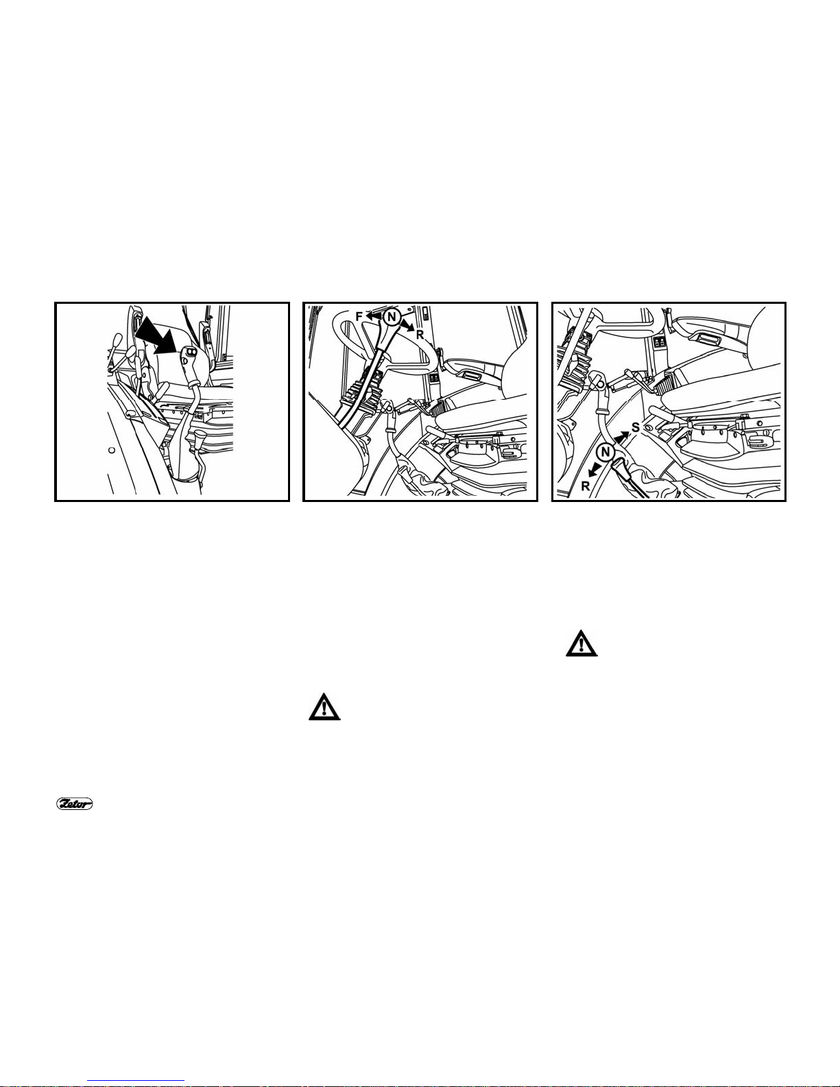
E149 E150 E151
REVERSING GEARSHIFT LEVER
F – forward run; lever forwards
N – neutral
R – reverse run; lever backwards
In combination with gear reduction and
torque multiplier, 16 forwards gears and
16 reverse gears are possible in total.
GEARSHIFT LEVER OF ROAD AND
REDUCED SPEEDS
R
road gears
N
neutral
S
reduced gears
Shifting is made with tractor at standstill.
TORQUE MULTIPLIER
The torque multiplier is controlled electro-pneumatically by means of buttons
situated on the gearshift lever.
The indicator light on the dashboard indicates the multiplier function.

45
ACQUAINTANCE WITH TRACTOR
E152 E153 E154
PTO SHAFT DRIVE ENGAGEMENT
The switches on the right cab pillar are
used to engage it.
The tractor standard model is equipped
with the 6-spline end of the rear PTO
shaft.
REAR PTO SHAFT GEARSHIFT
LEVER 540 AND 1000 RPM (OR 540E)
a -
1000 rpm (or 540E)
n -
neutral
b -
540 rpm
Shifting is made with tractor at standstill.
∗Tractor can be equipped with six-,
eight- or twenty-one-spline shaft end.
Speed shifting of either 540 or
1000 rpm is possible regardless
to assembled shaft end. The PTO
shaft speed and shaft end type
must be chosen depending on
the prescribed speed of the implemented machine.
REAR PTO SHAFT DRIVE CONTROL
LEVER
a -
independent speed of the PTO
shaft drive
- speed depends on the engine
speed
n -
neutral
b -
dependent speed of the transmission PTO shaft
- speed depends on the gear
shifted
Shifting is made with tractor at standstill.

46
ACQUAINTANCE WITH TRACTOR
E155 E156 E157
HAND BRAKE LEVER AND HITCH
LEVER FOR THE ONE-AXLE TRAILER
1. hand brake lever
2. hitch control lever for one-axle trailer
HYDRAULIC SYSTEM CONTROL
PANEL
The hydraulic system control panel (1) is
situated in the space of the right-hand
fender.
ADDITIONAL HYDRAULIC
DISTRIBUTOR CONTROL
The additional hydraulic distributor control
(2) is situated on the upper part of the
right-hand fender.
BATTERIES CUT-OFF SWITCH
During a long-term shutdown, repairs, failure or crash remember
to disconnect the battery by
means of the battery cut-off
switch immediately.
The battery cut-off switch is located on
the left-hand tractor side in front of the
cab.
a - battery connected
b - battery disconnected

47
ACQUAINTANCE WITH TRACTOR
E158 E159 E160
TRACTORS WITH TRAVELLING
SPEED OF 40 KM.H
-1
All tractor models with front driving axle,
which have brakes installed in front
wheels gear reductions, may reach the
travelling speed of 40 km.h
-1
.
FUEL TANK
The fuel tank is fitted on the right-hand
tractor side. The plastic fuel tank with
capacity of 120 litres is assembled as
standard for all tractor types.
Do not step on the fuel tank!
FUEL TANK DRAIN PLUG
The hole to drain impurities is located at
the bottom of fuel tank.
AVERAGE FUEL CONSUMPTION IN
LITRES PER OPERATING HOUR FOR
ZETOR TRACTORS
Tractor type Engine load
100% 80% 50%
Z 8541 18.42 14.44 9.21
Z 9541 20.34 16.27 10.17
Z 10541 22.63 18.11 11.32

48
NOTES

49
NOTES

50
NOTES

51
TRACTOR OPERATION
Be familiar with shifting pattern
and test all positions of shifting
lever with the stopped engine
before driving a new tractor.
Before driving under normal
operation, first make sure that the
operating condition of the tractor
corresponds to regulations of the
safe traffic operation.
Page
Before engine starting............................................................................................... 52
Engine starting..........................................................................................................52
If the engine does not start........................................................................................53
Signalling of glowing system failures.........................................................................53
Starter motor handling...............................................................................................53
Immediately after start...............................................................................................54
Engine preheating..................................................................................................... 54
∗Coolant heater......................................................................................................... 55
Starting the engine using the coolant heater.............................................................55
Gear-shifting..............................................................................................................56
Reversing shift lever..................................................................................................56
Road and reduced gear shifting................................................................................56
Shifting from lower to higher gear speeds.................................................................57
Shifting from higher to lower gear speeds.................................................................57
Torque multiplier .......................................................................................................58
Multiplier function indication......................................................................................58
Setting in motion .......................................................................................................59
Driving uphill
..............................................................................................................60
Driving downhill.........................................................................................................
60
Differential lock..........................................................................................................61
Front driving axle control...........................................................................................61
Driving with the front driving axle engaged ...............................................................61
Service brakes ..........................................................................................................62
Air brakes of trailers and semi-trailers.......................................................................62
Air pressure drop warning light..................................................................................62
Single and double-hose brakes.................................................................................63
Single-hose brakes ...................................................................................................63
Double-hose brakes.................................................................................................. 63
Hydraulic trailer brakes .............................................................................................64
Connecting and disconnecting the trailer hydrau lic brake q uick couplings...........................64
Stopping the tractor - parking brake..........................................................................65
Stopping the engine..................................................................................................65
Leaving the tractor ....................................................................................................65
Hydrostatic steering malfunction warning light.......................................................... 66
Important notification.................................................................................................66
52
TRACTOR OPERATION
E201
E202
E203
BEFORE ENGINE STARTING
Before starting the engine be sure that:
1. tractor is braked properly
2. main gearshift lever is in neu-
tral position.
If the clutch pedal is not depressed, the tractor cannot be
started - the start safety switch is
not actuated.
Note: Before starting proper we recommend to prime the fuel system by several
strokes of hand fuel delivery pump.
ENGINE STARTING
1. Insert the key into the ignition lock
("0" position).
2. Depress the clutch pedal.
3. Move the main gearshift lever into
neutral position.
4. Set throttle to increased fuel delivery
(approx. 1/2 of maximum delivery).
5. Turn the key from “0” position to "I"
position. The glow-plug indicator light
comes on.
6. Wait until the indicator light goes out
(the time depends on the coolant
temperature).
In case that the indicator light
flashes only instead of lighting,
the glowing system failed (see
Chapter Signalling of glowing
system failures). Have the indicated failure corrected at the
authorized service centre.
7. Immediately after the indicator light
has gone out (max. within 5 s), turn
the key from position "I" into position
"II" (start).
8. Release the key immediately after
starting the engine, it returns automatically into ”I” position. Do not op-
erate the starter for more than 15 s.
9. After starting the engine, gradually
reduce the fuel delivery.

53
TRACTOR OPERATION
E204 E205 E206
IF THE ENGINE DOES NOT START
Turn the key into position "0", wait 30
seconds and repeat the start.
Maximum 6 starting cycles are allowed
(15 seconds starting and 30 second
interruption make one cycle). Further
engine starting attempt is allowed after
cooling down of starter motor to the
ambient temperature.
Never help the stopping engine
by the starter motor. It may be
suffer damage this way.
SIGNALLING OF GLOWING SYSTEM
FAILURES
Flashing of the glowing indicator light
indicates failure in the glowing system.
- If the glo wing indicator light is flashing
once in a second with the stopped engine, glowing will take place in emergency regime as at low temperature
regardless to coolant temperature.
- If the glo wing indicator light is flashing
twice in a second with the stopped engine, the glowing is put of operation.
- If the glo wing indicator light is flashing
permanently with the engine running,
failure of the glowing regulator occurred and glowing was not finished. It
is necessary to correct the failure immediately, because there is danger of
battery discharging.
STARTER MOTOR HANDLING
It is forbidden to start the tractor by short circuit of starter
motor connectors!
Start the tractor from the
driver’s seat only!
When handling or repairing the
starter motor, remember to disconnect the negative battery
terminal and move all gearshift
levers into neutral position, including PTO shaft engagement!
Starter motor connectors are
covered with caps.

54
TRACTOR OPERATION
E207
E208
IMMEDIATELY AFTER START
After starting set the engine
speed to 800 - 1,000 rpm and let
the engine run at idle for about 2
minutes without load.
In the meantime check lubrication,
charging (indicator lights must go out)
and other functions assuring a correct
engine operation. Be sure to keep the
time of engine idle run without any load,
especially in winter season.
ENGINE PREHEATING
Continue to preheat the engine already while driving. W arming up the engine
by long idle run time or fast increase of speed is dangerous for the engine.
Do not exceed the engine speed of 2,000 rpm until the coolant te mperature
reaches 45 °C.

55
TRACTOR OPERATION
E209 E210
∗COOLANT HEATER
The coolant heater is installed on the
right-hand side of the engine block.
Output 1,000 W
Voltage 220 V
STARTING THE ENGINE USING THE COOLANT HEATER
The heater allows starting the engine at low ambient temperatur e by preheating the
coolant. The electrical system and its protection against ele ctrical shock hazard must
be done according to valid regulations.
1. Plug the heater first.
2. Plug the cable with connected heater to 220 V mains after.
With regard to reduction of engine wear when starting at low t emperatures, the producer recommends to use the heater. The preh eating time depends upon the ambient temperature (1 to 2 hours before supposed starting are sufficient).
Having finished the heating, unplug the mains first and the heater only after!
Electrical shock hazard!
It is necessary to ensure instruction of tractor operators and regular
revisions of the coolant heater including the inlet cabl e in accordance
with valid standards of the country, in which the tractor is operated,
minimum before each winter season.
56
TRACTOR OPERATION
E211 E212 E213
GEAR-SHIFTING
Tractors are equipped with the fourspeed synchronized gearbox, torque
multiplier, reversing unit and two-speed
reduction gear.
The main gearshift lever with buttons to
control the torque multiplier is used to
shift to gears in the four-speed gearbox.
The reversing lever is used to engage
forward and rearward tractor gears.
REVERSING SHIFT LEVER
Use the reversing shift lever to select the
tractor driving direction (forward or reverse).
F - forward drive (16 gears)
N - neutral
R - reverse run (16 gears)
The reversing gearbox has 16 reverse
gears, which are approximately so fast
as forward gears. Therefore consider it
well, which gear for the work you will
select.
Shift to the reversing gear with
the clutch pedal depressed at
tractor standstill.
ROAD AND REDUCED GEAR SHIFTING
S - road gear speeds
N - neutral
R - reduced gear speeds
The gear shifting of reduced gears of the
main gearbox is identical to gear shifting
of normal road gears.
The gearshift lever of road and
reduced gears may be shifted
with tractor at standstill only.

57
TRACTOR OPERATION
E214
SHIFTING FROM LOWER TO HIGHER
GEAR SPEEDS
Depress the clutch pedal (clutch disengaged). In the same time release the
throttle pedal and shift into proper higher
gear speed. Fluently release the clutch
pedal (the clutch starts engaging) and
simultaneously increase the engine
speed.
Note: To increase the service life of
synchronizers, it is possible to apply the
so-called double-declutching when shifting from lower to higher gears.
E215
SHIFTING FROM HIGHER TO LOWER
GEAR SPEEDS
Depress the clutch pedal and move the
gearshift lever through neutral position to
lower gear speed.
Note: To increase the service life of
synchronizers, it is possible to apply the
so-called “neutral acceleration” when
shifting from higher to lower gears.

58
TRACTOR OPERATION
E216 E217
TORQUE MULTIPLIER
The two-stage torque multiplier is standard for all tractor models.
Two buttons on the main gearshift lever
handle are used to shift to individual
gears of the two-speed multiplier.
Push the respective button without depressing the clutch pedal to shift. The
shifting of individual speeds is automatic
even on tractor under load.
Shifting of torque multiplier speeds:
H -
travelling speed increase
L -
travelling speed decrease
Note: When starting or stopping the
engine, always the “H” gear is shifted.
MULTIPLIER FUNCTION INDICATION
The indicator light on the dashboard
indicates the torque multiplier function
(operation velocity reduction).

59
TRACTOR OPERATION
E218
SETTING IN MOTION
1. Depress the clutch pedal.
2. Move the main gearshift lever into neutral.
3. Start the engine.
4. Set the engine speed to 750 up to 800 rpm.
5. Select road or reduced gear.
6. Move the reversing lever into the desired direction of tractor movement (forward
or reverse).
7. Shift into proper gear speed suitable for setting in motion.
8. Slightly increase the engine speed.
9. Prepare the parking brake for releasing.
10. Release the clutch ped al up to the point where the tractor starts to move and
simultaneously with the engine speed increasing, contin ue to release the clutch
pedal smoothly.
11. Fully release the parking brake.
12. Start smoothly and slowly.
Very fast start can cause overload of the drive train, increased
fuel consumption, excessive tire
wear and damage to transported
load. Shift to 1
st
gear to start the
tractor only when driving while
hauling a heavy trailer uphill and
in heavy terrain.

60
TRACTOR OPERATION
E219 E220
DRIVING UPHILL
Shift from higher to lower speed
in time when going uphill, to
avoid engine speed dropping
below 800 rpm and do not admit
driving leading to engine stopping
in consequence of overloading.
DRIVING DOWNHILL
Driving downhill without shifted
gear is forbidden. If driving down
a longer hill, shift to such lower
gear the sharper one the hill is. If
possible, shift to the lower speed
gear still before driving downhill.
Note: Remember that the gear you use
reliably for driving uphill is safe enough
to drive downhill.

61
TRACTOR OPERATION
E221 E222 E223
DIFFERENTIAL LOCK
Push the switch to engage the lock; the
switch will return in the initial position
after releasing.
Engagement of the differential lock is
indicated by the lighting symbol in the
switch.
When depressing the brake pedals, the
differential lock will disengage automatically.
Do not use the differential lock
when driving in a curve.
FRONT DRIVING AXLE CONTROL
In the basic position, the front driving
axle is engaged.
Engagement of the front driving axle is
signalled by the lighting symbol in the
switch.
Disengagement is made with the switch
that is situated on the dashboard.
a - Front drivin g axle disengaged
b - Front drivin g axle engaged
With the stopped tractor (braked tractor,
stopped engine, ignition key in “0” position), the front driving axle is engaged.
At sudden air pressure drop in
the tractor air pressure system,
the front driving axle is automatically engaged.
DRIVING WITH THE FRONT DRIVING
AXLE ENGAGED
Use the front driving axle when rear
wheels are slipping to increase the
tractor traction force. On the road a nd
on hard ground the driving with the front driving
axle engaged is permissible within maximum
speed of 15 km/h (the driving with the front
driving axle engaged on the road and on hard
ground causes excessive wear of front tires).
Permanent engagement of front driving
axle is permitted if the agriculture machine or implement is attached to front of
the tractor. This condition is specified in
Operator’s Manual of each particular
machine. Maximum permitted speed of
the tractor combination is 15 km/h in that
case.
62
TRACTOR OPERATION
E224 E225 E226
SERVICE BRAKES
Foot brakes are of disc, wet, hydraulically actuated, double pedal type with
automatic pressure compensator.
Both brake pedals must be
latched together on the move.
Use unlatched pedals to brake
the right or left wheel separately
when working in terrain and field
at low travelling speed only.
Note: When driving downhill in sharp descent with a trailer or semi-trailer being
equipped with air or hydraulic brakes, it is
necessary to apply the service brake already from the beginning of the downhill
drive!
When braking with one brake
pedal, the trailer brakes are not
actuated!
AIR BRAKES OF T RAILERS AND SEMI-TRAILERS
Control of air brakes of trailers (semitrailers) is performed in such manner that
the brake effect of both vehicles is synchronized.
When driving with the hitched
trailer or semi-trailer, the service
brake pedals must be connected
together and secured with latch!
When braking with one brake
pedal, the trailer air brakes do
not operate.
Note: At pressure drop, the relief valve
puts secondary appliances (differential
lock, disengagement of front driving axle)
out of operation.
AIR PRESSURE DROP WARNING
LIGHT
The red indicator light located on the
dashboard indicates the air pressure
drop below the critical value of 450 kPa.
Tractor with a braked trailer or
semi-trailer must not continue to
drive when the air pressure drops
below the critical value of 450
kPa in the air system, until the air
pressure increases.

63
TRACTOR OPERATION
E227 E228 E229
SINGLE AND DOUBLE-HOSE
BRAKES
1. coupling head of single-hose air brak e
system.
2. coupling heads of double-hose air
brake system.
After disconnecting or without
any hitched trailer or semi-trailer,
it is necessary to cover the couplings with caps.
SINGLE-HOSE BRAKES
The operating pressure has been set
with the control valve to 600 ± 20 kPa.
The permitted speed of the tractor combination with a hitched
trailer (or semi-trailer) loaded to
maximum weight, as approved
for the stated tractor model, is 30
km/h!
The maximum permitted speed of
the vehicle combination is stated
as the maximum permitted speed
of the slower vehicle of this com
bination.
DOUBLE-HOSE BRAKES
The operating pressure has been set to
740 ± 20 kPa. The left coupling cap head
is marked with yellow colour (braking
branch); the right coupling cap head is
marked with red colour (filling branch).
The permitted speed of the tractor
combination with a hitched trailer
(or semi-trailer) loaded to maximum weight, as approved for the
stated tractor model, is 40 km/h!
The maximum permitted speed of
the vehicle combination is stated
as the maximum permitted speed
of the slower vehicle of this combination.

64
TRACTOR OPERATION
E230 E231
HYDRAULIC TRAILER BRAKES
The control of hydraulic trailer (semi-trailer) brake an d the tractor brake is performed
so that their braking effect is synchronized. The oil pressure is created by the oil,
which is drawn from the gear-type disengaging hydr aulic pump (1). The brake valve
(2) is installed behind the pump into the circuit.
The brake fluid pressure from master brake cylinders controls the trailer brake valve
in dependence on the force acting on the brake pedal. Pressure in the br ake cou pling
(3) must be 12 - 15 MPa at maximum depression of the brake pedal. The trailer brake
valve prefers the brake system function to the hydraulic system function. When
bleeding the tractor brakes, do not forget to bleed also the brake valve. In case that
during depression of service brake pedals shocks occur in the piping of the hydraulic
circuit, it is necessary to de-aerate the hose (4) leading fr om the brake valve (2) to
the quick coupling (3).
Brake pedals must be connected and secured with latch when driving the
tractor with attached trailer or semi-trailer!
When braking with one brake pedal, the hydraulic trailer brakes are n ot functioning.
CONNECTING AND DISCONNECTING
THE TRAILER HYDRAULIC BRAKE
QUICK COUPLINGS
When connecting and disconnecting the quick couplings, pay
particular attention to the residual
oil, which remains in a socket or
plug of the quick coupling.
For environmental protection
reasons, it is necessary to wipe
the residual oil after each disconnection of quick coupling
using a piece of cloth.

65
TRACTOR OPERATION
E232 E233 E234
STOPPING THE TRACTOR - PARKING
BRAKE
Proceed smoothly under normal conditions. Remember to do shortly before
stopping:
1. Depress the clutch pedal and apply
the service brake.
2. Move the main gearshift lever into
neutral.
3. Set the parking brake to secure the
tractor against accidental movement
always when stopping the tractor. The
indicator light on the dashboard indicates the parking brake setting.
STOPPING THE ENGINE
Let the tractor engine cool down after a
full load operation.
1. Reduce the engine speed to 800 1,000 rpm before stopping the engine
and let it run at idle for about 5 minutes.
2. Move the hand throttle control lever of
the fuel delivery into MIN position.
3. Pull up the controller of the engine
stopping device and turn it in the
pulled position. After the engine stops
push the controller back
4. After stopping the engine it is possible
to turn the ignition key from “I” position into “0“ position (with the engine
at standstill only - the charging warning light must come on).
LEAVING THE TRACTOR
Be sure to remove the key from the ignition lock in “0” position before leaving the
tractor safety cab (the key cannot be
removed when in “I” or “II” position).
The tractor must be secured
against spontaneous setting in
motion as follows:
1. shut the engine off
2. shift to 1
st
gear
3. set the parking brake
In addition, when the tractor stands on a
hill, be sure to underlay the wheels with
chocks.
Lock the cab.
Note: With the stopped engine the front
driving axle is automatically engaged.

66
TRACTOR OPERATION
E235 E236
HYDROSTATIC STEERING MALFUNCTION WARNING LIGHT
When the oil pressure drops below 120
kPa behind the pump, it means a malfunction of hydrostatic steering pump,
which is indicated by lighting of the corresponding symbol on the dashboard.
Note: The warning light can flash during
the engine start or at low engine speed;
if it goes out after starting the engine or
after engine speed increase, there is no
malfunction. The system is OK.
IMPORTANT NOTIFICATION
In case that the oil pressure / charging /
hydrostatic steering malfunction warning
light comes on during the tractor operation, shut the engine off immediately and
have the malfunction located and corrected at the authorized service centre.
In such a manner you prevent a serious
defect or tractor accident.

67
NOTES

68
NOTES

69
TRACTOR RUNNING-IN
Page
General rules for running in a new tractor during the first 100 operating hours.........70
In the course of the first 10 operating hours..............................................................70
After 70 operating hours............................................................................................ 71
More than 100 operating hours.................................................................................72

70
TRACTOR RUNNING-IN
E251 E252
GENERAL RULES FOR RUNNING IN A
NEW TRACTOR DURING THE FIRST
100 OPERATING HOURS
Within the first 100 operating hours:
- Load the engine normally.
- Avoid the partial engine load during
operation.
- Avoid the long operation at idle run.
- Check often the engine oil level
(increased oil consumption is normal in
that time).
- Check bolted connections, especially
connections of structural parts of the
tractor.
- Immediately remedy all problems
found. You will avoid subsequent
damages and/or also endangering the
traffic safety.
- Keep the similar procedure also after
the tractor general overhaul.
IN THE COURSE OF THE FIRST 10
OPERATING HOURS
- Run in the tractor under traffic
conditions.
- Tighten fasteni ng nuts of front and rear
wheels including connections bead/
rim to specified torques.

71
TRACTOR RUNNING-IN
E253 E254 E255
AFTER 70 OPERATING HOURS
Replace the hydraulic oil filter element. If
necessary, add oil into gearbox. Check
the oil level, which should reach the
flattened part of oil dipstick.
Replace the hydraulic oil filter
element when the oil is cold.
Proceed according to chapter
“Hydraulic oil filtration“ in this
manual.
AFTER 70 OPERATING HOURS
Drain the hot engine oil and replace the
full-flow engine oil filter. Fill in the engine
with new oil to the prescribed level (after
engine cranking and oil level stabilizing
up to the upper mark of oil dipstick)
AFTER 70 OPERATING HOURS
- Check tightening of cylinder heads (on
cold engine).
- Check the valve clearance (0.25 ±
0,05 mm - on cold engine).
Carry out the check of cylinder
head tightening and adjustment
of valve clearance at the
authorized service centre within
the framework of the tractor
guarantee inspection.

72
TRACTOR RUNNING-IN
E256
MORE THAN 100 OPERATING HOURS
After running in period you can work with
the tractor without any restrictions.
The operating regime for tractor engine:
Recommended
operating speed
1,400 - 2,300 rpm
Idle speed 700 ± 25 rpm
Operating
oil pressure
0.2 - 0.5 MPa
Oil pressure
at idle speed
min. 0.05 MPa
Max. coolant
temperature
106°C

73
NOTES

74
NOTES

75
TRANSPORTATION USE
Be sure that the tractor technical
condition corresponds to safe
traffic operation requirements
before driving.
When a trailer or an implement is attached, check the hitching and a proper
fixing of the transported load. Never
leave the tractor when in move to attach
the trailer alone. Pay also attention to
safety of your assistant.
Page
Front hook.................................................................................................................76
Multi-stage quick adjustable hitch CBM ....................................................................76
Height adjustment and removal of the multi-stage hitch CBM...................................76
Automatic mouth of the multi-stage hitch CBM .........................................................77
Modular system of trailer and semi-trailer hitches.....................................................77
Swinging draw bar bracket module...........................................................................77
Swinging draw bar.....................................................................................................77
Swinging draw bar bracket c/w fixed pintle module................................................... 78
Bracket c/w ø 80 ball module.................................................................................... 78
One-axle trailer hitch CBM........................................................................................ 78
Attachment of one-axle trailer ................................................................................... 79
Disconnection of one-axle trailer...............................................................................79
∗Draw bar..................................................................................................................79
Trailer and semi-trailer implementation.....................................................................80
Maximum allowable vertical static loads of trailer and semi-trailer hitches................ 81

76
TRANSPORTATION USE
E301 E302 E303
FRONT HOOK
The front hook has been designed to pull
the tractor without any attached trailer or
other attached implements only.
Use the pull bar or rope to perform the tractor recovery.
Never use chains! Hazard of
mortal injury when the chain
ruptures!
It is forbidden to use tractor axles
(particular tractor wheels) as a
winch to recover the bogged
down tractor.
MULTI-STAGE QUICK ADJUSTABLE
HITCH CBM
It serves to connect the two-axle or
lighter one-axle trailers. The hitch mouth
is height adjustable. At work with various
agricultural implements it is necessary to
change the height of the hitch or to remove it as need be.
HEIGHT ADJUSTMENT AND
REMOVAL OF THE MULTI-STAGE
HITCH CBM
By moving the control lever in the arrow
direction (1) you will unlock the lever,
and by following moving the lever to
position (2) the arresting pins (3) will
engage; hereby the multi-stage hitch is
released and it can be set in height or it
can be removed. After releasing from
position (2) the arresting pins (3) will
move out and the lever will automatically
return into the initial position.

77
TRANSPORTATION USE
E304 E305 E306
AUTOMATIC MOUTH OF THE MULTISTAGE HITCH CBM
Move the lever (1) in the arrow direction
to engage the pin (3) into the upper position, which is indicated by the slided-out
warning indicator (4) - see Fig. (A).
After the mouth seats on the tow ring,
the pin will automatically slide into ring of
the trailer to be coupled. The hitch pin (3)
can be lowered manually by moving the
lever (2) in the arrow direction. The
slided-in warning indicator (4) indicates
the pin inserting in place - see Fig. (B).
Remember to make sure whether
the warning indicator is slided in
always after the trailer attachment as per Fig. (B).
MODULAR SYSTEM OF TRAILER AND
SEMI-TRAILER HITCHES
Types of modules:
Fig. (B) - swinging draw bar bracket
Fig. (C) - swinging draw bar bracket c/w
fixed pintle
Fig. (D) - bracket c/w ø 80 ball
Removal - Fig. (A):
1. Unscrew the locking bolt (1).
2. Secure the module against fall,
unlock and remove pins (2).
3. Move the module down out of the
bracket.
Installation is a reverse procedure to
removal.
SWINGING DRAW BAR BRACKET
MODULE
The swinging draw bar bracket module is
situated in the multi-stage hitch bracket.
SWINGING DRAW BAR
Removal:
1. Unlock and remove pins (1).
2. Move the swinging draw bar out in
the arrow direction.
Installation is a reverse procedure to
removal.

78
TRANSPORTATION USE
E307 E308 E309
SWINGING DRAW BAR BRACKET
C/W FIXED PINTLE MODULE
Carry out the removal and installation of
the swinging draw bar as per Chapter
“Swinging draw bar“. Attachment of the
tow ring to the fixed pintle (3):
1. Unlock and remove pin (1).
2. Lift the locking wedge (2) in the arrow
direction.
3. Connect the tow ring to the fixed
pintle (3).
4. Return the locking wedge (2) into the
initial position and lock it with pin (1).
BRACKET C/W Ø 80 BALL MODULE
The bracket with ø 80 ball is used
to hitch the semi-trailers, which
are fitted with hitch stated for the
ø 80 ball.
Hitch unlocking - see Fig. (A):
Move the lever (1) in the arrow direction
until the locking wedge (2) is pushed
away.
Hitch locking - see Fig. (B):
Move the lever (1) in the arrow direction
until the locking wedge (2) is pushed
back in place.
ONE-AXLE TRAILER HITCH CBM
The one-axle trailer hitch may be
equipped with hook (A) ), which is
designed to hitch one-axle trailers having
the tow ring meeting the standard ISO
5692 (inner ring ∅ 50 mm and ring
height 30 mm) or the swinging draw bar
(B). The hitch hook is lifted and lowered
hydraulically by means of longitudinally
adjustable telescopic pull rods.
Replacement of hook for the swinging
draw bar (C):
1. Lower the hitch.
2. Unlock and remove pin (1).
3. Remove the hook in the arrow
direction.
Installation of the swinging draw bar is a
reverse procedure to removal.
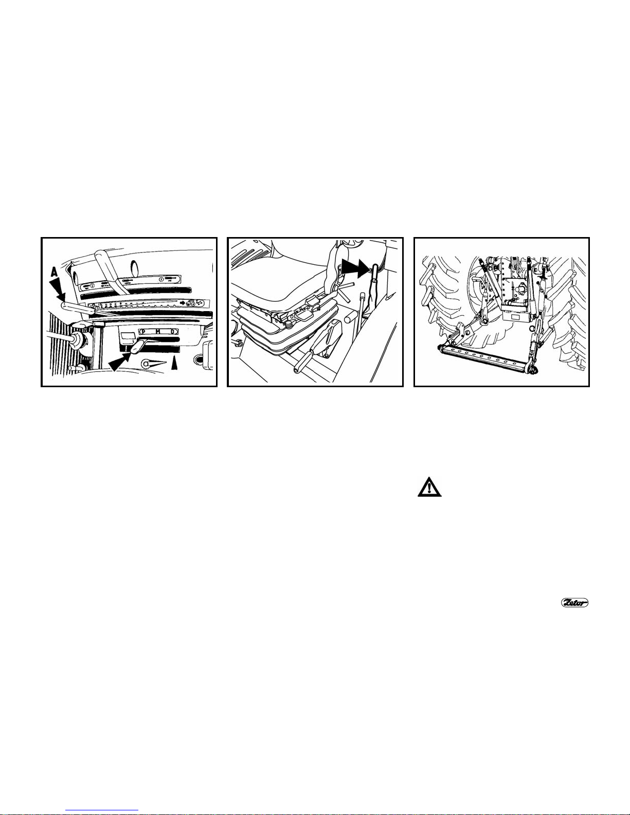
79
TRANSPORTATION USE
E310 E311 E312
ATTACHMENT OF ONE-AXLE
TRAILER
It is carried out by means of the hydraulic
inner circuit lever (A) with selected position regulation. The hitch hook together
with trailer tow ring is hydraulically raised
into position where the latches lock down
under the hitch carrier pins. Hydraulic
arms must be subsequently lowered so
that the hook latches could seat into
carrier pins - telescopic pull rods must
not be stretched.
DISCONNECTION OF ONE-AXLE
TRAILER
Disconnecting is made after slight lowering of the hitch by hydraulic inner circuit
lever with selected position regulation.
Move the hitch control lever rearwards.
The lever is located to left hand side
from the driver’s seat. Use the hydraulic
inner circuit lever to lower the hitch and
disconnect the trailer tow ring.
∗DRAW BAR
The draw bar is height adjustable by the
hydraulic lifting system within its whole
lifting range. Only those agricultural
implements that permanently load the
drawbar downwards can be attached to
the draw bar.
Remove the multi-stage hitch and
swinging draw bar when working
with the draw bar.

80
TRANSPORTATION USE
E313
TRAILER AND SEMI-TRAILER
IMPLEMENTATION
The tractor must be implemented only
with a suitable tractor-trailer after matching up the service brakes of tractor with
air or hydraulic brakes of trailer. Static
rear axle load must not exceed the value
of maximum allowable axle load when
implemented with a semi-trailer.

81
TRANSPORTATION USE
MAXIMUM ALLOWABLE VERTICAL STATIC LOADS OF TRAILER AND SEMI-TRAILER HITCHES
Hitch type
Allowable
vertical
static
load
Ø hitch
pin
Hitch type
Allowable
vertical
static
load
Ø hitch
ball pin
Hitch type
Allowable
vertical
static
load
Ø hitch
ball pin
15 kN
lower
position
18 kN
31 mm
15 kN
lower
position
18 kN
38 mm
15 kN
28 mm
15 kN
lower
position
18 kN
43 mm
15 kN
lower
position
18 kN
50 mm
Maximum weight of implemented braked tr ailer or semi-trailer must not exceed the value mentioned on the tractor type
plate and the value mentioned in the vehicle registrati on do cument. T he maximu m v ehic l e co mbinati on spee d is li mited by
the maximum allowed speed of the slower vehicle.

82
TRANSPORTATION USE
MAXIMUM ALLOWABLE VERTICAL STATIC LOADS OF TRAILER AND SEMI-TRAILER HITCHES
Hitch type
Allowable
vertical
static
load
Ø hitch
pin
Hitch type
Allowable
vertical
static
load
Ø hitch
ball pin
Hitch type
Allowable
vertical
static
load
Ø hitch
ball pin
7.5 kN
31 mm
18 kN
80 mm
7.5 kN
44.5
mm
22kN
47 mm
10 kN
Maximum weight of implemented braked tr ailer or semi-trailer must not exceed the value mentioned on the tractor type
plate and the value mentioned in the vehicle registrati on do cument. T he maximu m v ehic l e co mbinati on spee d is li mited by
the maximum allowed speed of the slower vehicle.

83
NOTES

84
NOTES

85
PTO DRIVE OF AGRICULTURAL MACHINES
Before attachment of the implement, driven by means of the
tractor PTO shaft, check the
speed compatibility of both, it
means tractor PTO shaft and
implement driven shaft (540 rpm
or 1,000 rpm). Different PTO
speed values may cause serious
damages and injuries.
Page
PTO shaft operation............................................................................................................86
Front and rear PTO shaft control ........................................................................................86
Rear PTO shaft - engagement of dependent and independent speed............................... 87
Rear PTO shaft - shifting of 540 and 1,000 rpm or 540E of the PTO shaft........................87
Front PTO shaft...................................................................................................................87
Replaceable ends of rear PTO shaft .................................................................................. 88
Maximum transmitted output............................................................................................... 88
Drive of machines with high inertial masses (crushers, rotary devices, harrows, etc.) ...... 89

86
PTO DRIVE OF AGRICULTURAL MACHINES
E351 E352 E353
PTO SHAFT OPERATION
1. When working with the PTO shaft, take care for proper fitting of all guards.
2. On termination of the work, always reassemble the PTO shaft guard.
3. Connecting and disconnecting of the implement cardan shaft to the rear PTO shaft
should be performed only when the tractor engine is stopped, PTO shaft is disengaged and the shifting lever of dependent and independent PTO speed is shifted
into N – neutral position!
4. Connecting and disconnecting of the implement articulated shaft to the front PTO
shaft should be performed only when the tractor engine is stopped and PTO shaft is
disengaged!
5. Any repairs or cleaning of implement parts driven by means of the PTO shaft
should be performed only when the engine is stopped, PTO shaft is disengaged
and the shifting lever of dependent and independent PTO speed is shifted into N –
neutral position!
FRONT AND REAR PTO SHAFT CONTROL
Switches situated on the right-hand cab
pillar are used to engage and disengage
the PTO shaft (at minimum engine speed
1,500 rpm). The switches are fitted with
mechanical latches (1), which protect
against unintentional switching-on. To
change over the switch, push the latch
down.
P -
switch controls the front PTO shaft
Z -
switch controls the rear PTO shaft
When both switches are turned on, both
PTO shafts (front and rear) are put in
operation. The engagement of PTO
shafts is indicated by the lighting symbol
in the switch.

87
PTO DRIVE OF AGRICULTURAL MACHINES
E354 E355 E356
REAR PTO SHAFT - ENGAGEMENT
OF DEPENDENT AND INDEPENDENT
SPEED
Shifting is made with the lever (1) on
tractor at standstill.
a -
independent speed of PTO shaft
(PTO shaft speed depends on
the engine speed)
n -
neutral position
Use it to make the attachment of
the agricultural machine cardan
shaft easier. The end of the rear
PTO shaft is easy to rotate.
b -
dependent speed of PTO shaft
(engine speed and sense of
rotation depends on the shifted
gear speed and position of the
reversing lever)
REAR PTO SHAFT - SHIFTING OF 540
AND 1,000 RPM OR 540E OF THE PTO
SHAFT
Shifting is made with the lever (1) on
tractor at standstill.
As standard the tractor is equipped with
combination of 540 and 1,000 rpm of the
PTO shaft and as option the tractor may
be fitted with combination of 540 and
540E rpm of the PTO shaft.
a -
1,000 rpm or 540E rpm
n -
neutral
b -
540 rpm
Shifting of 540 and 1,000 (or
540E) rpm is possible regardless
of the installed splines of the shaft
end. The PTO shaft speed and
the shaft end must be selected
according to the prescribed speed
of the implement.
FRONT PTO SHAFT
The front PTO shaft is fitted with fixed
21-spline end and speed 1,000 rpm.
On customer’s wish the tractor may be
fitted with the front PTO shaft with various directions of rotation:
a - identical with the direction of engine
rotation (standard)
b - opposite direction to engine speed
(∗ on customer’s wish)

88
PTO DRIVE OF AGRICULTURAL MACHINES
E357
E358
REPLACEABLE ENDS OF REAR PTO
SHAFT
Standard the tractor is equipped with the
fixed 6-spline end.
∗ On customer’s wish the tractor may be
equipped with 6- or 21-spline replaceable end of the PTO shaft.
Replacement procedure:
1. Use circlip pliers to remove the
circlip (1).
2. Pull the replaceable end in the arrow
direction (2) to remove it.
3. Installation is a reverse procedure to
removal, pay special care to installation of the circlip (1).
Replacement of the shaft end
must be done with the stopped
engine.
Select the PTO shaft speed and
end type according to the implement prescribed speed.
Shifting of 540 and 1000 or 540E
rpm is possible regardless of the
number of splines of the installed
shaft end.
MAXIMUM TRANSMITTED OUTPUT
PTO shaft
Transmitted
output
front
1,000 rpm 45 kW*
rear
1,000 rpm full engine output
540 rpm full engine output
540E rpm full engine output
* If it applies to the transmitted output
without shocks, the value of the maximum transmitted output may be increased to 50 kW.

89
PTO DRIVE OF AGRICULTURAL MACHINES
DRIVE OF MACHINES WITH HIGH
INERTIAL MASSES (CRUSHERS, ROTARY DEVICES, HARROWS, ETC.)
The cardan shaft of these machines
must be fitted with the so-called free
engine clutch, which disconnects the
transmission of torque at reaction from
machine to tractor.

90
NOTES

91
NOTES

92
NOTES

93
HYDRAULIC SYSTEM
The hydraulic system is intended for
lifting and lowering of agricultural
machines and implements attached to
the rear three-point hitch.
Page
Hydraulic system....................................................................................................... 94
Hydraulic pump.........................................................................................................94
Hydraulic oil filtration.................................................................................................94
Function of control elements.....................................................................................95
Hydraulic inner circuit................................................................................................95
Inner circuit control lever........................................................................................... 95
Selection lever of control mode.................................................................................96
Response rate control lever ...................................................................................... 96
Hydraulic outer circuit................................................................................................97
Outer circuit control lever ..........................................................................................97
Rear outlets of hydraulic outer circuit........................................................................98
Connection and disconnection of quick couplin gs............................................................98
Oil volume supplied from hydraulic outer outlets.......................................................99
Control of single-acting cylinder..............................................................................100
Control of double-acting cylinder.............................................................................100
Selective control valve ............................................................................................101
Control of selective control valve.............................................................................102
Connection of machines and implements to hydraulic outer circuit......................... 103

94
HYDRAULIC SYSTEM
E401 E402 E403
HYDRAULIC SYSTEM
It consists of inner and outer circuits.
The source of the pressure oil is the
gear-wheel pump.
The oil is delivered from common filling
of the gearbox and axle final drive gear.
HYDRAULIC PUMP
The hydraulic pump cannot be
disengaged. When the engine runs, the
hydraulic pump is in function.
Hydraulic pump is alternatively supplied
in two sizes:
Pump type Pump capacity
1. UD 20 50 l/min
2. UD 16 40 l/min
The relief valve limits the pressure
induced in the hydraulic circuit to 18
MPa.
HYDRAULIC OIL FILTRATION
The hydraulic pump sucks the oil through
the suction filter located on the left-hand
side of the gearbox. You can replace the
oil filter element without draining the oil
from gearbox.
The oil will spill from the filter body
during the filter cartridge replacement. A
clean vessel of approximately 10 l
volume must be used. Prepare a new
cartridge in advance. Pour the spilled oil
back into gearbox (it holds in case that
the filter element must be replaced
outside of recommended time for the oil
or filter element replacement).

95
HYDRAULIC SYSTEM
E404 E405 E406
FUNCTION OF CONTROL ELEMENTS
1. Control lever of hydraulic outer
circuit
2. Control lever of hydraulic inner
circuit
3. Selection lever of hydraulic control
mode
4. Response rate control lever
HYDRAULIC INNER CIRCUIT
1. Inner circuit control lever
2. Selection lever of control mode
3. Response rate control lever
4. Adjustable stop (keeps the inner
circuit control lever in selected
position)
INNER CIRCUIT CONTROL LEVER
It controls:
a - Lifting of implement into transport
position (max. lifted)
b - Height adjustment of three point
hitch with implement when position
control is selected and height
adjustment of ploughing depth with
draft or mixed control is selected
c - Setting of so called free (floating)
position when working with an
implement equipped with its own
supporting wheel

96
HYDRAULIC SYSTEM
E407 E408
SELECTION LEVER OF CONTROL MODE
The lever has three positions marked P, M or D
P -
This marks the position control, at which the implement attached to the
three-point hitch is automatically kept in constant height (position) with
regard to the tractor.
M -
This marks the mix control, which is a combination of position and draft
controls. This is suitable especially for ploughing at soils with variable soil
resistance.
D -
This marks draft control, at which the implement attached to the three-point
hitch is automatically readjusted depending upon the soil resistanc e change.
All modes of control enable also work with implement having a s upporting wheel in
the so-called free (floating) position.
The selection lever of control mode must be moved into P position during
transport of the implement!
RESPONSE RATE CONTROL LEVER
The lever controls the hydraulic valve in
the distributor, which distributes the oil
flow to inner and outer circuit.
The oil flow in inner circuit is minimum, if
the lever is moved in the direction (MIN)
from the driver’s seat.
By the oil flow restriction at draft or mix
control the hydraulic system response
rate is reduced, for example when
ploughing under variable soil conditions.

97
HYDRAULIC SYSTEM
E409 E410
HYDRAULIC OUTER CIRCUIT
The hydraulic outer circuit delivers the
pres-sure oil into hydraulic implements
connected to hydraulic outer outlets
equipped with quick couplings.
Quick coupling sockets have inner
diameter 12.5 mm and correspond to
ISO international recommendation.
OUTER CIRCUIT CONTROL LEVER
The lever has three positions marked on label:
a -
Pressure is in quick coupling "1", quick coupling "2" is c onnected with return
line. Lever is moved into its rear margin position. The lever must be held in
this position; otherwise it is automatically moved into position "b" (neutral).
b -
Neutral position (locked). Outlets to quick couplings "1" and "2" are closed and
oil flow in attached hydraulic implement is blocked. The lev er is automatically
held in this position by spring.
c -
Floating (free) position. Both quick couplings "1" and "2" are connected with
return line and oil can freely flow in both directions. The lever is locked in this
position by ball lock, which is situated in the slide valve.
d -
Pressure in quick coupling "2", quick coupling "1" is connected with return line.
Lever is moved into its forward margin position. The lev er must be held in this
position; otherwise it is automatically turned into position "c" (floating position).

98
HYDRAULIC SYSTEM
E411 E412
REAR OUTLETS OF HYDRAULIC
OUTER CIRCUIT
The basic type of hydraulic outer circuit
outlets is equipped with three quick
couplings located on the panel.
According to position of the
corresponding control lever, pressure oil
is distributed into quick couplings "1" and
"2". The third quick coupling "0" is
connected directly with the space of the
axle final drive gear and is intended for
the oil returning from outer hydraulic
implements (for example from rotary
hydraulic motors, etc.).
A - Arrangement of quick couplings
corresponds with a tractor that is
equipped with hydraulic system
without selective control valve
B - Arrangement of quick couplings
corresponds with a tractor that is
equipped with hydraulic system with
selective control valve
Attached implements using oil
filling of hydraulic outer circuit
must be filled with the same kind
of oil as recommended for the
tractor transmission!
CONNECTION AND DISCONNECTION OF
QUICK COUPLINGS
When connecting and disconnecting the quick couplings,
pay high attention to residual oil,
which remains in the socket
and/or on the quick coupling plug.
For environmental reasons, it is
necessary to remove this residual
oil with a piece of cloth after each
disconnection of quick couplings.

99
HYDRAULIC SYSTEM
E413
OIL VOLUME SUPPLIED FROM
HYDRAULIC OUTER OUTLETS
For maximum possible delivered oil
volume see the following chart.
With high oil supply, the hydraulic
pump might suck the air inside
and the pump could be damaged.
In case that after disconnecting of the
implement the oil level drops in the
gearbox (caused by its permanent
pumping from tractor into hydraulic
circuit of the implement), it’s necessary
to add the missing volume of oil.
Type of work: in plain terrain
Max. oil supply: 20 litres
Gearbox filling:
standard filling dipstick
mark (A)
Type of work: at slope
Max. oil supply: 13 litres
Gearbox filling:
standard filling dipstick
mark (A)
Type of work: in plain terrain
Max. oil supply: 27 litres
Gearbox filling: dipstick mark (B)
gearbox filling increased by 7 litres
maximum permissible oil volume in
gearbox
Type of work: at slope
Max. oil supply: 20 litres
Gearbox filling: dipstick mark (B)
gearbox filling increased by 7 litres
maximum permissible oil volume in
gearbox

100
HYDRAULIC SYSTEM
E414 E415 E416
CONTROL OF SINGLE-ACTING
CYLINDER
Single-acting hydraulic cylinder is al ways
connected to quick coupling "1".
Lifting Lever in position "a"
(pressure in quick
coupling "1")
End of lifting Lever is shifted to
position "b" – neutral
Lowering Lever is shifted to
position “c“ – floating
End of lowering Lever is shifted to
position “b“ – neutral
CONTROL OF DOUBLE-ACTING
CYLINDER
Double-acting hydraulic cylinder is
connected to quick coupling "1" and "2".
Movement in
one direction
Lever in position "a"
(pressure in quick
coupling "1")
End of
movement
Lever in position "b"–
neutral
Movement in
opposite
direction
Lever in position "d" -
(pressure in quick
coupling "2")
End of
movement
Lever in position "b"–
neutral
Lightened
position
Lever in position "c"
(low pressure in
quick coupling “2”)
The outer circuit control lever
must be moved as quickly as
possible over position „c" (floating
position) when working with
double-acting cylinder, because
both sides of cylinder are
connected with the return line
and it means that uncontrolled
movement of the piston rod might
occur.
 Loading...