


ZETOR
This present operation manual provides information with operation and maintenance of your new tractor the
PROXIMA PLUS.
Despite the fact that many of you have rich experience with operation of other types of tractors, please read this
manual carefully to acquaint yourself with its contents as thoroughly as possible.
In the manual, you can find a lot of information how to utilise the best your tractor with various types of work.
When following the given principles of operation and maintenance of the tractor and safety of driving, your tractor
will become your reliable partner for many years.
The manufacture of your tractor wishes you thousands hours of satisfying work.
ZETOR
Brno
1

Information on the technical data, construction, equipment, material and appearance is valid at the time of printing. The manufacturer reserves the right of changes.
2

The operation manual includes description, operation and maintenance of standard accessories of the tractor. The accessory that is not installed by the manufacturer (manufacturing plant) as standard is not covered by the warranty. The
service cheque book for tractors is not
included in the operation manual; it is a
separate brochure that is delivered to
you with purchase of a new tractor.
CONTENTS
Page
Location of serial numbers..........................................................................................5
Safety instructions for the user.................................................................................... 7
Preventive daily maintenance ...................................................................................21
Getting to know the tractor........................................................................................27
Driving.......................................................................................................................61
Running-in the tractor................................................................................................81
Transport use............................................................................................................85
Drive of farming machines.........................................................................................93
Hydraulic system.....................................................................................................101
Mechanical hydraulics.............................................................................................107
Electro-hydraulic system......................................................................................... 121
Hitches....................................................................................................................139
Change of wheels tread..........................................................................................147
Additional weights...................................................................................................153
Electric installation ..................................................................................................159
Tractor maintenance ............................................................................................... 169
Maintenance instructions ........................................................................................189
Adjustments ............................................................................................................211
Essential technical parameters ............................................................................... 223
Index.......................................................................................................................245
3
TRACTORS PROXIMA PLUS
TRACTORS WITH FRONT DRIVING AXLE (4 x 4):
Type of
the tractor
Z90 60 64,3
Z100 66 70,4
Z110 74 78,4
Engine power
(kW)
EC 24 2000/25/EC
G1
4

LOCATION OF SERIAL NUMBERS
G2
5
LOCATION OF SERIAL NUMBERS
When ordering spare parts and with all written and oral communication use please the data of your tractor that you shall write
down to the following frames.
Type of the tractor
Zetor Proxima Plus Z90
Zetor Proxima Plus Z100
Zetor Proxima Plus Z110
Designation "to the right", "to the left", "in
the front", "in the back" is meant in direction of drive of the tractor.
During production, the manufacturer reserves the right to carry out changes in
the construction and equipment for the
purpose of technical progress.
Serial number of the tractor
6
Serial number of the engine
G3

SAFETY INSTRUCTIONS FOR THE USERS
Pay proper attention to those sections of the operation and maintenance manual that are marked with this symbol .
You can find this symbol with all important warnings that relate to safety of operation.
Follow these warnings and behave with special attention in these cases!
Inform your colleagues and other users about these warnings.
The chapters marked with this symbol should be read thoroughly before any operating, repair or adjustment action on the
tractor.
You can find this symbol with all important warnings that relate to operation, adjustments and repairs of the starter.
Follow these warnings and behave with special attention in these cases!
This symbol appears with the parts of the operation manual that relates to protection of the environment.
This symbol indicates the tractor accessories mounted by the manufacturer on the customer’s request.
∗
Instruction manual´s passages related only to models equipped with DPF (diesel particle filter) are labelled with this symbol.
GENERAL SAFETY REGULATIONS
1. The tractor may only be operated by a trained worker having a valid qualification to drive the tractor and who is acquainted
thoroughly with the operational and safety principles.
2. In addition to the warnings relating to safety and given in the operational manual, it is necessary to respect all the generally applicable safety and traffic regulations of the country in which the tractor is used.
PROPER CLOTHING
3. Do not wear loose clothing and free flying long hair.
4. When executing any work, use suitable (prescribed) personal protective means (working shoes, gloves, etc.)
7

SAFETY INSTRUCTIONS FOR THE USERS
STARTING THE ENGINE
5. Starting of the engine by driving from slopes is not allowed.
6. Make the tractor moving for the purpose of starting the engine using other tractor or another vehicle is permitted only with use
of a tow bar.
7.Start the engine only from the driver’s seat with the shifting level in neutral position and clutch pedal depressed. Danger of
death when starting the engine using short-circuited terminals of the starter!
8. The key in the ignition box shall be in position "I".
9. When warming up the engine using an electric heater, first plug in the power supply cord to the heater and then to the mains
socket. When the engine is warm, first disconnect the supply cord from the mains socket.
DRIVING
10. Hoses of hydrostatic steering, brakes and fuel system shall be checked regularly and in case that some traces of damage are
observed, replace the damaged components. The traces of damage include, for example, cracks, loose pre-stressing of hose
connections (this can be verified by easy pulling out the hose from the coupling) and mechanical damages of hoses. The hoses
with specified life span shall be replaced immediately after termination of the specified period.
11. When driving with trailers and implements on roads the brake pedals shall be connected by a latch.
12. Brakes and steering shall be always in perfect condition.
13. Driving downhill without shifted any gear is forbidden!
14. Special attention shall be paid to driving a tractor on slopes, muddy, sandy, icy and uneven surfaces.
15. Observe the permitted angle of the gradient accessibility, i.e. max. 12°.
16. Respect the total permitted weight of the vehicle train, given on the type plate of the tractor or mudguard of the rear wheel.
17. When driving through road bends, do not use the differential lock.
18. Getting on and off the moving tractor is forbidden.
19. When driving a tractor with agricultural machines suspended on the front three-point suspension reduce travel speed of the
tractor to 15 km.h
20. When driving a tractor with machines suspended in the rear hitch, loading of the steered axle shall not be reduced under 20%
of the immediate weight of the vehicle train. In case of travel speed reduced to 20 km/h, loading of the steered axle may be reduced to 19% of the immediate weight of the vehicle train (vehicle train up to 4.5t) and to 18% of the immediate weight (vehicle
train over 4.5t).
-1
.
8

SAFETY INSTRUCTIONS FOR THE USERS
TRANSPORT OF VEHICLES, OPERATION
21. The tractor may transport only so many people as specified in the MOT certificate of the vehicle.
22. The persons that are not charged to work with the accessories of the tractor may not stay between the tractor and the hitched
machined (tools).
23. Before you bring the tractor in motion, check whether an unauthorised person or barrier obstructs your drive.
24. With aggregation of the tractor with machines and tools with great tractive resistance, when speed of the engine decreases
and the engine has a tendency to stop, the reduction gears 1R, 2R may not be used to work with these machines.
EXTRICATION, PULLING
25. Ung bars or ropes for extrication of a stuck tractor.
Never use chains! A risk of death in case of a chain rupture!
26. When extricating a tractor it is dangerous to stay close the towing rope.
27. A front hook is installed on the frame of the tractor; this hook can only be used for towing of the tractor itself, i.e. without trailer
or other additional equipment.
28. Then pushing other vehicles (trailers, etc.) by the tractor never use freely inserted balks or bars between the tractor and the
pushed object.
LEAVING THE TRACTOR
29. Do not park the tractor with carried tools in lifted position.
30. Before you leave the tractor, do not forget to brake the tractor using the hand brake, shift a gear and reversing lever move to
position for driving forward, remove the key from the ignition box and lock the cabin.
31. Use left side to get out of the tractor. Look around whether some vehicle does not come near to jeopardise your safety when
getting out of the vehicle.
32. When getting out of the tractor, use footboards and hold tight to the grab handles. Pay special attention close to the shifting
lever and lever of manual regulation of fuel supply.
33. When leaving the tractor with engine running apply the hand brake.
9

SAFETY INSTRUCTIONS FOR THE USERS
ONLY WITH ENGINE STOPPED
34. All works connected with refilling of fuel, cleaning, lubrication and adjustments of the tractor or suspension machines may only
be carried out with engine stopped and stopping of movable parts of the tractor, except check of function of brakes, hydraulics
and recharging of the battery.
35. Before removing the bonnet it is always necessary to stop the engine. In closed rooms the engine of the tractor may run only
if sufficient ventilation is provided. Exhaust gases are harmful for human health.
PRINCIPLES OF FIRE SAFETY
36. Carry out refilling of fuel with engine stopped.
37. In summer season do not refill fuel tank to its full capacity. Wipe immediately spilled fuel.
38. Do not refill fuel in vicinity of open flame and do not smoke.
39. When inspecting level of electrolyte in the battery, do not smoke and do not use open flame. Pay attention to consistent ob-
servation of fire safety instructions in environment of increased risk of fire (haylofts, straw stacks, etc.).
40. In case that the tractor is equipped with a fire extinguisher, have it still available.
PROTECTION OF HEALTH AND THE ENVIRONMENT
41. The tractors are not equipped with any special filters of air supplied to the cabin. Therefore the tractors are not designed for
work with aerosols and other harmful substances. Kerosene, diesel oil and other oil products that are used for operation and
treatment of the tractor may cause skin diseases with direct contact, show irritation effects to mucous membranes, eyes, digestive and upper respiratory tract. Some of them may cause general poisoning when swallowed.
42. The workers that come into contact with oil products are obliged to observe safety and hygienic directives, use suitable protective means and work in well ventilated rooms.
WHEN WORKING WITH OIL PRODUCTS
43. After end of your work of before taking a food it is necessary to wash the hands thoroughly with a non-irritating washing
preparation and use a suitable protective hand cream.
44. When connecting and disconnecting quick-couplings of hydraulic circuits remove, using any textile material, excessive hydraulic oil remaining in the socket or plug of the quick-coupling.
10

SAFETY INSTRUCTIONS FOR THE USERS
DISPOSAL OF WASTE
45. With disposal of the tractor or its parts (including its operational fluids) after termination of their service life it is necessary to
follow the applicable laws and executing notices to the laws of the country in which the tractor is used. Based on the act on
waste, when selling the tractor, the final dealer of the tractor is liable to inform the consumer about the way of back taking of
some used parts of the tractor. These include oils and other operational fluids, batteries and tyres. Back taking of these used
products shall be carried out without any demands for any payment from the consumer for this back taking.
DAILY PREVENTIVE MAINTENANCE
46. Perform this daily or at least every 8-10 working hours of the engine.
SAFETY CABIN
47. In case that the protective frame of the cabin is damaged from corrosion, accident or otherwise, the safety cabin shall be re-
placed for a new one.
AIR-CONDITIONING
48. In any case do not dismount, change direction or otherwise manipulate with the fitting of the air-conditioning system. This
may cause a sudden escape of the cooling medium and fast local cooling. A contact of such component with skin may result in a
serious injury.
49. The air-conditioning system is equipped with quick-couplings that allow, if necessary, to separate the cab from the tractor
body without any leakage of the cooling medium. Any interventions into the air-conditioning system should be performed by a
specialised service shop.
11

SAFETY INSTRUCTIONS FOR THE USERS
ELECTRIC INSTALLATION
50. No additional modifications of electric installation of the tractor shall be carried out (such as connection of other elec-
tric appliances) due to its possible overloading!
51. Values of electric installation:
Nominal voltage 12 V =
Grounded minus ( - ) pole
Use of starting trucks or other auxiliary sources with a different voltage or polarity may cause serious damages to the tractor.
52. When manipulating with the battery pay special attention and avoid short circuits. The tractors are equipped with a battery
disconnector that shall be switched off before any manipulation with the battery.
53. The tractors cannot be operated with disconnected battery; this may cause serious damages to the tractor.
12

SAFETY INSTRUCTIONS FOR THE USERS
FH13N002
FRONT PASSENGER´S SEAT NOTIFICATION
Transportation of personnel on front passenger’s seat is allowed only with road
transportation.
- Transportation of front passenger outside the seat designed for this pur-
pose is forbidden.
- Using the seat for front passenger during the work with a tractor (e.g. during
the work on the fields) is explicitly forbidden.
- The use of safety belt on front passenger’s seat is governed by valid regulations. In this respect, keep the regulations valid in the country, where the
tractor is operated.
13
FH13N003
PROTECTION OF CAB AGAINST
AEROSOLS
The cab of Zetor tractors in standard design is not designed for work with aerosols and other health hazardous substances.
The level of cab protection in standard
design complies with
EN 15695-1:2009 standard - level 2
(only dust proof cab)

SAFETY INSTRUCTIONS FOR THE USERS
THE LEVEL OF EXTERNAL NOISE OF TRACTOR
The exposition to the effects of high levels of noise for a longer period of time may lead to hearing disorders or deafness.
Protect your hearing with protective means, e.g. headphones, ear plugs etc.
Resulting levels of noise when measuring noise for hearing of a person near a tractor
Based on European directive 2009/63/EC – Amendment VI
TRACTORS PROXIMA PLUS
Model Proxima Plus 90 Proxima Plus 100 Proxima Plus 110
Travel speed 30 km 40 km 30 km 40 km 30 km 40 km
Tractor noise levels when travelling dB(A) 81 80.5 80.5 80.5 81.5 80.5
Tractor noise levels when standing dB(A) 79.5 82.5 80.5 81 81.5 81.5
14

SAFETY INSTRUCTIONS FOR THE USERS
THE LEVEL OF INTERNAL SOUND OF TRACTOR
The exposition to the higher sound levels for longer periods of time may lead to hearing disorders or deafness. Protect
your hearing with protective measures, e.g. headphones, ear plugs etc.
Resulting levels of noise when measuring noise for hearing of driver
Based on European directive 2009/76/EC – Amendment VI
TRACTORS PROXIMA PLUS
Model Proxima Plus 90 Proxima Plus 100 Proxima Plus 110
Travel speed 30 km 40 km 30 km 40 km 30 km 40 km
Noise levels – Closed windows dB(A) 80.5 78.5 79.5 78 80 78.5
15

SAFETY INSTRUCTIONS FOR THE USERS
THE LEVEL OF VIBRATIONS ON DRIVER´S SEAT
ZETOR tractors are classified in A category in classes I and II. “A” category includes all tractors with set level of vibrations owing
to similar specifications of construction:
Results of measurement on testing bench are listed in the following table pursuant to directive 78/764/EEC. The value a*
adjusted value of effective acceleration balanced according to vibration movement.
The following table is valid for all type series of Zetor tractors.
Class I & II
Brand of seat Model Springing
(1)
a*
wS
(m/s²)
(2)
a*
wS
(m/s²)
GRAMMER MSG85/721 mechanical 1.18 0.8
GRAMMER MSG95A/721 pneumatic 1.16 1.1
MARS 78/764-73xx mechanical 1.25 1.23
SEARS 3008 mechanical 1.24 1.06
SEARS 3045 pneumatic 1.13 1.03
(1) Values corresponding to driver’s weight of 50 kg.
(2) Values corresponding to driver’s weight of 120 kg.
is an
wS
16

SAFETY INSTRUCTIONS FOR THE USERS
TRACTORS EQUIPPED WITH FRONT END LOADER
Zetor Tractors in standard design are designed for utilization in agriculture and are not designed for special purposes.
Tractors designed for operation within the European Union must be equipped, in case of using front end loader, with a protective
structure (FOPS – Falling Object Protective Structure) protecting drivers from potential falling objects.
It is necessary to observe applicable local valid regulations in countries which are not part of the European Union.
Two types of cab roofs are mounted to Zetor tractors.
1. Standard cab roof
2. Cab roof designed for tractors equipped with front end loader meeting the OECD code 10 (FOPS) conditions.
Tractors ZETOR supplied already from production with front end loader are equipped with cab roof according to point 2.
From safety reasons, series ZETOR tractors supplied without front end loader with standard roof pursuant to point 1 must not be
equipped or used with front end loader.
In case of additional front end loader assembly, it is necessary to equip tractor with cab roof pursuant to point 2.
Only front end loaders approved by ZETOR TRACTORS may be mounted to ZETOR tractor.
Additional assembly of front end loader approved by ZETOR TRACTORS can be done only by authorized ZETOR
service.
It is forbidden to use front end loaders unapproved of by ZETOR TRACTORS.
Not observing this instruction may cause serious accidents.
Carefully observe instructions for use supplied by the manufacturer of front end loader.
17

SAFETY INSTRUCTIONS FOR THE USERS
PRINCIPLES FOR OPERATING TRACTORS EQUIPPED WITH FRONT END LOADER
Carefully study operation manual supplied by the manufacturer of front end loader.
In case of discord of Principles for operating tractors equip ped with front end loader and operation manual for
front end loader, which was supplied by the manufacturer of front end loader, the wording listed in operation
manual supplied by the manufacturer of front end loader shall apply.
- The use of front end loader for transporting material at places accessible to the public is forbidden.
- The use of front end loader for transporting material in places inaccessible to the public is possible only in a limited way. In
such case, instructions in user’s manual supplied by the loader manufacturer must be observed.
- Observe local valid regulations at all times.
- A strict ban on transportation and lifting of people by means of loader is in effect.
- No matter whether the front end loader is loaded or empty, no-one may stand in front of the loader if it is in lifted position. When
driving with a lifted loader, there is a risk of load transported by front end loader falling (there is a risk of disrupting the balance
of the tractor).
- Never leave the tractor standing with the loader in lifted position.
- If it is necessary to open the bonnet of the engine at intervention, disconnect the front end loader first or secure hydraulic rollers
of front end loader by metallic props designed for this purpose.
- Hydraulic circuit of the front end loader is designed in such a way to endure the maximum operation pressure of 20 MPa (200
bar). Do not do any changes on couplers of hydraulic circuit hoses.
- Any front end loader ZETOR mounting without observing the recommendation of ZETOR TRACTORS valid to the day of purchase revokes the validity of guarantee for the whole of supply.
- The loader may be used, maintained and repaired only by people who perfectly know the machine and who are informed about
potential risks.
- When driving on roads do not transport any material on the front end loader.
- It is necessary to observe special instructions related to accidents prevention and general rules related to technical safety, labour medicine, labour hygiene and regulation defining operation on roads.
- The manufacturer does not bear any responsibility for any potential damage incurred as a result of changes conducted on the
loader without their consent.
- Do not ever adjust the front end loader by yourselves and do not use the adjusted front end loader without prior ZETOR´s approval. The loader may become dangerous as a result of not observing these instructions. ZETOR TRACTORS shall not be
held responsible in case of any damage or injury.
18

SAFETY INSTRUCTIONS FOR THE USERS
- Use front end loader without additional weights on the tractor (danger of mutual contact). The load of front and rear drive axle
must not exceed the maximum permitted load listed in the manual. The use of front end loader requires mounting of counter
weight in the rear part of the tractor.
- Each working tool was reconstructed for the purpose of specific usage and has its own tolerance of resistance and tightness.
- It is forbidden to use front end loader for cultivating soil and stubbing. Such work needs to be done with a special tool, front end
loader is not designed for doing this.
- Using controls which would set the loader into motion without driver holding the gear shifting lever is strictly forbidden and results in installation not meeting the prescribed standard.
- To penetrate the loaded material, better use the kinetic energy of the tractor rather than pressing force which causes higher
strain of both the loader and the tractor.
- Do not overload hydraulic parts if the load is too heavy or pistons are in end positions.
- Control the loader exclusively from driver’s seat, if you are sitting on driver’s seat.
- Do not leave the seat if you have not blocked any movement of controls.
- No people can be present in the working zone of the loader.
- When working with a lifted loader, mind electric and external cables etc.
- Loader/tractor set needs to be parked on a horizontal and solid base, the arms of the lifting device must be set in the lower position. After using the front end loader, park the tractor and lower the tool to the ground.
You will find more information in user’s manual to front end loader.
Important notification:
Work always safely and with consideration.
19

SAFETY INSTRUCTIONS FOR THE USERS
ZETOR TRACTORS USED FOR WORK IN THE WOODS
Standard tractors Zetor do not provide sufficient protection for operation in forest terrain as, for example, protection against a falling tree or branch on a cab or penetration of objects to a cab.
If Zetor tractor is utilized for forest work, a tractor operated within the European Union must be protected against these risks.
It is necessary to observe applicable local valid regulations in countries which are not part of the European Union.
To ensure this protection, it is advisable to conduct assembly of a specific protective structure, like for example FOPS / OPS (Falling Object Protective Structure / Operator Protective Structure), tested according to standards for forest machines.
Only forest superstructures approved by ZETOR TRACTORS can be mounted to ZETOR tractors.
In case of additional assembly of further tractor equipment for working in the woods, full responsibility is borne by the supplier and
manufacturer of the protective structure that all the safety regulations (e.g: OPS / FOPS), all the conditions of homologation (e.g.
the area of driver’s view, lighting, parameters, permissible weight etc.) are met, same as for the provision of due assembly of protective equipment. The supplier/manufacturer of protective construction is also obliged to conduct all the necessary validation
(approval) steps required by the legislature of the country in which the tractor is operated.
20

DAILY PREVENTIVE MAINTENANCE
Carry out this maintenance every day or at least every 8-10 working hours of the engine
21
G4

DAILY PREVENTIVE MAINTENANCE
G5 E6g G716c
TIGHTNESS OF THE FUEL SYSTEM
Check tightness of the fuel system, including the fuel tank discharge plug.
Eliminate immediately all leakages.
LEVEL OF OIL IN THE ENGINE
The oil gauge rod can be found on the
right side of the engine. After screwing
and pulling out the rod, check level of oil
in the engine and tightness of connections of the engine lubrication system.
Keep level of oil between the gauge rod
marks.
22
COOLING SYSTEM
Check tightness of connections of the
engine cooling system and level of cooling fluid in the expansion tank.
The expansion tank is accessible after
opening of the front bonnet. Refill the
missing volume up to the upper gauge
mark MAX. The minimum permissible
level of cooling fluid is at the gauge mark
MIN.
Release the overpressure lid after the cooling fluid has cooled
down. Risk of scalding!

DAILY PREVENTIVE MAINTENANCE
G735a G9 G751b
FLUID BRAKES
Check tightness of fluid brakes, fluid control of the clutch and level of brake fluid
in the expansion tank. The tank can be
found on the left side of the tractor, in
front of the cabin and is accessible after
lifting of the front bonnet.
Keep level of the brake fluid within 3/4
(max.) and 1/2 (min.) of the tank volume.
When manipulating with the
brake fluid, keep strictly cleanness. Check level of brake fluid
every day before driving.
AIR BRAKES OF THE TRAILER
Check tightness of the air system of the
brakes and effectiveness of brakes of the
tractor with a trailer.
HYDRAULIC BRAKES OF THE TRA ILER
Check tightness of hydraulic brakes of
the trailer and effectiveness of brakes of
the tractor with a trailer.
23
HYDROSTATIC STEERING
Using the oil gauge rod check level of oil
in the hydrostatic steering tank that can
be found on the left side of the tractor. It
is accessible after lifting of the front bonnet.
If necessary, refill oil up to the oil gauge
rod mark that defines its correct volume.
Check condition of all hoses of the hydraulic steering circuit for any damage
and oil leakage.
Check tightening of bolts and nuts of
steering rods and levers.

DAILY PREVENTIVE MAINTENANCE
G11 G710b E13
TYRES AND WHEELS
Check air pressure in the front and rear
tyres. According to nature of work, adjust
correct pressure. Check and tighten if
necessary all screws of the front and
read wheels (connection rim/disk and
disk/wheel shaft).
Never drive with loose wheel
screws!
AIR CLEANER
Maintenance of the air cleaner shall be
carried out after indication of the indicator of clogging.
The indicator is accessible after lifting of
the bonnet. It is located close to the inlet
pipe elbow.
24
FILTRATION OF THE CAB
Check and clean if necessary air filters
for ventilation of the cab in the front
overhang of the roof.
Replacement of filters depends on
amount of dust in the working environment.
Partial regeneration can be carried out
by dusting of blowing with compressed
air.
Carry out cleaning or replacement of filter cartridges after dismounting of cover
grilles in the roof overhang.
At the customer’s request we supply filters with active carbon.
Don’t clean the filter; don’t flush it
with compressed air.
DAILY PREVENTIVE MAINTENANCE
E14 E15 G16
SUSPENSION EQUIPMENT
Check condition of suspension and connection equipment including the trailer.
AFTER WORK WITH FRONT-CARRIED
MACHINESI
After work with front-carried machines:
− Check tightness of connections of the
external hydraulic circuit for control of the
front three-point suspension.
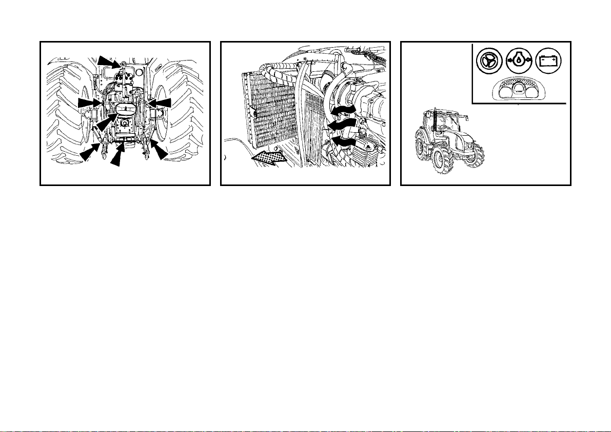
Clogging of radiators:
1. Tilt up the bonnet.
2. Release and slide out the A/C con-
denser to the left side of the tractor.
3. Clean the front walls of the engine ra-
diator (A/C condenser) using compressed air (blow air in direction from
the engine).
4. Remove remaining dirt from the
space under the bonnet (to prevent its
re-sucking).
25
SHORT FUNCTIONAL TEST
After starting the engine check whether
the indicator of hydrostatic steering fault,
indicator of engine lubrication and indicator of recharging are off.
Check function and tightness of hydraulic steering circuits.

NOTES
26

The user of the tractor shall learn
beforehand the recommended
procedures and instructions for
safe operation of the tractor. It is
too late to do it during operation!
GETTING TO KNOW THE TRACTOR
Safety cabin .............................................................................................................. 29
Opening of doors from outside .................................................................................. 29
Opening of doors from inside .................................................................................... 29
Rear window .............................................................................................................30
Side window .............................................................................................................. 30
Right rear panel......................................................................................................... 31
Window mirrors ......................................................................................................... 31
Sun shield .................................................................................................................32
Internal lighting.......................................................................................................... 32
Washer nozzle .......................................................................................................... 33
Washer tank .............................................................................................................. 33
Washer activation...................................................................................................... 33
Passenger´s seat ...................................................................................................... 34
Driver’s seat Mars Svratka ........................................................................................ 35
Adjustment according to the driver’s weight.............................................................. 35
Longitudinal adjustment ............................................................................................35
Vertical adjustment.................................................................................................... 35
Driver’s seat Grammer Maximo................................................................................. 36
Driver’s seat Grammer S........................................................................................... 36
Driver's seat Sears .................................................................................................... 37
*Air filter with active carbon....................................................................................... 38
Heating control panel, ∗A/C, ∗radio........................................................................... 39
Heating valve control (A)........................................................................................... 39
Fan control (B) .......................................................................................................... 39
∗Air-condition switch () .............................................................................................. 39
Control of air circulation in the cabin (D) ...................................................................40
Correct function of the heating and a/c systems .......................................................40
Fast warming-up of the cabin space ......................................................................... 40
Fast cooling of the cabin space................................................................................. 41
Operation of heating of air-conditioning with work of the tractor................................ 41
When the cabin is cooled .......................................................................................... 42
Control panel on the cab right piller........................................................................... 43
Page
27

GETTING TO KNOW THE TRACTOR
*Tilt steering wheel.................................................................................................... 44
*Tilt and telescope steering wheel ............................................................................ 44
Air-condition and heating registers (a) ...................................................................... 45
Front windshield (B) defrosting ................................................................................. 45
Dashboard ................................................................................................................ 47
Display of pto speed ................................................................................................. 50
Switchers, switches and levers ................................................................................. 51
Lights switcher (a)..................................................................................................... 52
Switch for switching over lights in the mask and on the roof (b)................................ 52
Switch of warning lights (e) ....................................................................................... 52
Front driving axle switch (f) ....................................................................................... 53
Pushbutton of rear differential lock (j) ....................................................................... 53
Combined switch of indicator lights, low and high beams and flash lights (k) ........... 53
Ignition box ............................................................................................................... 54
Key in position "0" ..................................................................................................... 54
Key in position "i" ...................................................................................................... 54
Key in position ”ii”...................................................................................................... 55
Lever of manual refulation of fuel.............................................................................. 55
Control of engine stop............................................................................................... 55
Pedals....................................................................................................................... 56
Lever of shifting gears............................................................................................... 56
Scheme of shifting of gears ...................................................................................... 56
Reversing lever ......................................................................................................... 57
Lever of shifting of road and reduced gears.............................................................. 57
Torque multiplier ....................................................................................................... 57
Switching on output shaft drive ................................................................................. 58
Lever of shifting of speed 540 (or 540e) and 1,000 rpm of the rear output shaft ...... 58
Lever of switching on rear output shaf drive ............................................................. 59
Lever of hand brake and hitch for single-axle trailer ................................................. 59
Tractors with travel speed 40 km.h
Fuel tank ................................................................................................................... 60
Draining plug of the fuel tank .................................................................................... 60
Battery disconnector ................................................................................................. 60
-1
......................................................................... 60
28
Page
GETTING TO KNOW THE TRACTOR
SAFETY CABIN
Use commonly left side of the
tractor for getting in and out the
cabin.
Use footboards for getting in and
out the cabin and hold tight to the
grab bars.
Pay special attention in space of
the shifting lever and lever of
manual regulation of fuel.
G101 E102 E103
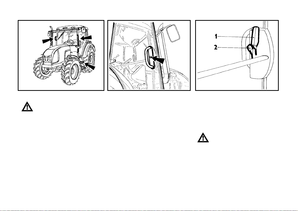
OPENING OF DOORS FROM OUTSIDE
The cabin doors can be locked from the
outer side. Doors can be opened after
unlocking and pulling the grab bar.
29
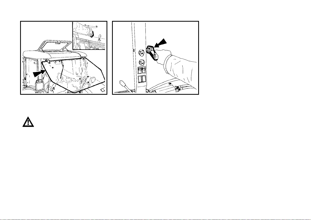
OPENING OF DOORS FROM INSIDE
1. Lever for opening of the door from inside.
2. Lever for opening of the lock from inside.
With full opening the door is held by a
gas strut.
It is forbidden driving with open
door due to its possible damage.
GETTING TO KNOW THE TRACTOR
E104 E105
REAR WINDOW
It is provided with a grab bar and in open
position it is held by gas struts.
When driving on an uneven
surface it is advisable to secure
the window in closed position due
to danger of a glass break.
Before commencement of work
with machines carried in the rear
three-point suspension make
sure if there is no risk of a
collision between the carried tool
with maximum stroke of the rear
three-point suspension and open
rear window. In case of a collision
it is recommended to work with
rear window closed.
SIDE WINDOW
In partly open position it is held by a
plastic window handle. The window can
be opened by lifting the handle upwards
and its pushing to lock it in the groove;
this secures the window in a fixed
position.
30

GETTING TO KNOW THE TRACTOR
E108 E109
RIGHT REAR PANEL
The right rear panel includes a storage
place for a PET bottle (1), socket 12V (2)
and cigarette lighter (3).
WINDOW MIRRORS
Before driving or commencement of work
adjust window mirrors to enable observation of whole driving lane or working field.
31

GETTING TO KNOW THE TRACTOR
FH13N009 F13BN014
SUN SHIELD
You can draw out the sun shield by pulling the handle in the direction of the arrow. The shield gets back to initial position after pressing the button (1) by an
applicable shield.
INTERNAL LIGHTING
To be turned on and off by means of a
button marked with the arrow.
32

GETTING TO KNOW THE TRACTOR
E110 E111 E112
WASHER NOZZLE
The nozzle is installed on the bonnet in
front of the windscreen and adjustable
using a needle or steel wire with diameter 0.8mm.
WASHER TANK
The tank is installed on the rear wall of the
cabin on the outer side.
Volume of the tank is 2.5 litres. In winter
season it is necessary to fill it with antifreeze mixture for windscreen washers.
33
WASHER ACTIVATION
The key in the ignition box shall be in
position II. The windscreen washer can
be activated after pressing of the front
two-speed wiper on the right column of
the cabin. The maximum time of continuous run of the washer pump is 20 s.

GETTING TO KNOW THE TRACTOR
FH12N020
PASSENGER´S SEAT
Passenger´s seat is tiltable and placed on the left mudguard of the cabin.
SEAT TILTING OUT
Passenger´s seat to be tilted out in the direction of an arrow (1) upward. Locking of the seat is done automatically
SEAT TILTING
Lift the passenger´s seat in the direction of an arrow (2), pull the lever (3) to the direction of the driver´s seat, tilt the seat in the direction of an arrow (4).
34

GETTING TO KNOW THE TRACTOR
E113 E114 E115
DRIVER’S SEAT MARS SVRATKA
ADJUSTMENT ACCORDING TO THE
DRIVER’S WEIGHT
Cushioning of the seat is adjustable for
driver’s weight from 50 to 120kg. Adjustment is carried out using a rotary
square handle. Indicator of adjustment of
the weight can be found in a recess of
the seat rear cover. Cushioning stroke is
120mm.
Do not adjust during drive!
Risk of an accident!
LONGITUDINAL ADJUSTMENT
The seat can be adjusted longitudinally
within range ±75mm (11 positions) after
unlocking by the left lever.
35
VERTICAL ADJUSTMENT
The seat can be adjusted vertically by a
lever on the right side within range
±30mm from the middle position to both
marginal positions.

GETTING TO KNOW THE TRACTOR
E116
DRIVER’S SEAT GRAMMER MAXIMO
1. Lever for adjusting of cushioning of the seat according weight of the driver (adjustment by turning in direction as shown on the pictogram on the seat bellow).
2. Lever of longitudinal adjustment of the seat (located on the right side of the seat).
3. Turning of the seat (can be turned by 20° to both sides).
4. Control of adjustment of absorption of vibrations of the seat (tilting of the controller
forwards adjusts a floating position of the seat).
5. Control of adjustment of the seat inclination.
6. Control of adjustment of the back shape.
7. Height-adjustable backrest (pulling or pushing in direction of the arrow adjusts the
backrest within range 170mm).
8. Tiltable armrest.
9. Control of adjustment of the armrest (turning of the controller adjusts height of the
armrest).
DRIVER’S SEAT GRAMMER S
Here only items 1, 2 and 5 are used.
36

GETTING TO KNOW THE TRACTOR
P13N003
DRIVER'S SEAT SEARS
The driver's seat Sears can be made with a mechanical (A) or pneumatic (B) suspension.
1. The seat suspension adjustment controller according to the driver's weight (turn it in the direction based on icons shown on the
seat bellows)
2. The seat height adjustment controller (release the controller to increase the seat height, tighten the controller to decrease the
seat height)
3. The longitudinal seat adjustment lever (pull the lever to adjust the seat lengthwise, return the lever back to its original position
to lock the longitudinal adjustment)
4. The seat backrest inclination adjustment controller (pull the lever to adjust the seat backrest inclination, return the lever back
to its original position to lock the backrest position)
5. Foldable armrest
6. The armrest height locking adjustment (release the controller to adjust the height of the armrest, tighten the controller to lock
the armrest position)
7. The seat vibration absorption setting (move the controller up to get the float seat position, move the controller to the lower
position to lock it)
8. The seat height adjustment and seat suspension adjustment according to the weight of the driver (push the controller to increase the air pressure in the pneumatic suspension of the seat - when the driver´s weight is bigger, pull the controller to decrease the air pressure in the pneumatic suspension of the seat - at the lower weight of the driver
37

GETTING TO KNOW THE TRACTOR
F13BN015
*AIR FILTER WITH ACTIVE CARBON
Filters with active carbon are installed instead of the standard dust filter and replacement is carried out in the same way as in the common filters. The filter should be located with the white surface on the grid. Installation directions are stated in the chapter “Instructions for Maintenance”.
The filter is used only when spraying pesticides, after the work the paper filter should
be reinstalled, because the carbon filter would be choked with dust after a short period of time. Upon work the re-circulation controller should be in the position “air is
drawn into from the outside”.
The fan controller should be in the position “fan maximum work”.
• WARNING: The filter does not provide full protection against toxic substances.
• When handling the filter, wear protective gloves.
• Don’t clean the filter; don’t flush it with compressed air.
DANGER: The filter with active carbon should be replaced after every 200
hours or 36 months (manufacture date is stated on the filter). If you can smell
pesticides in the cabin, replace the filter immediately and check the cabin sealing. Used filters should be disposed in special disposal centres.
When spraying pesticides and
using the heating filter with active
carbon, the re-circulation controller should be in position “air is
drawn into from the outside” and
the fan controller should be in the
position “fan maximum work” to
create overpressure in the cabin.
38

GETTING TO KNOW THE TRACTOR
F13BN009 E118 E119
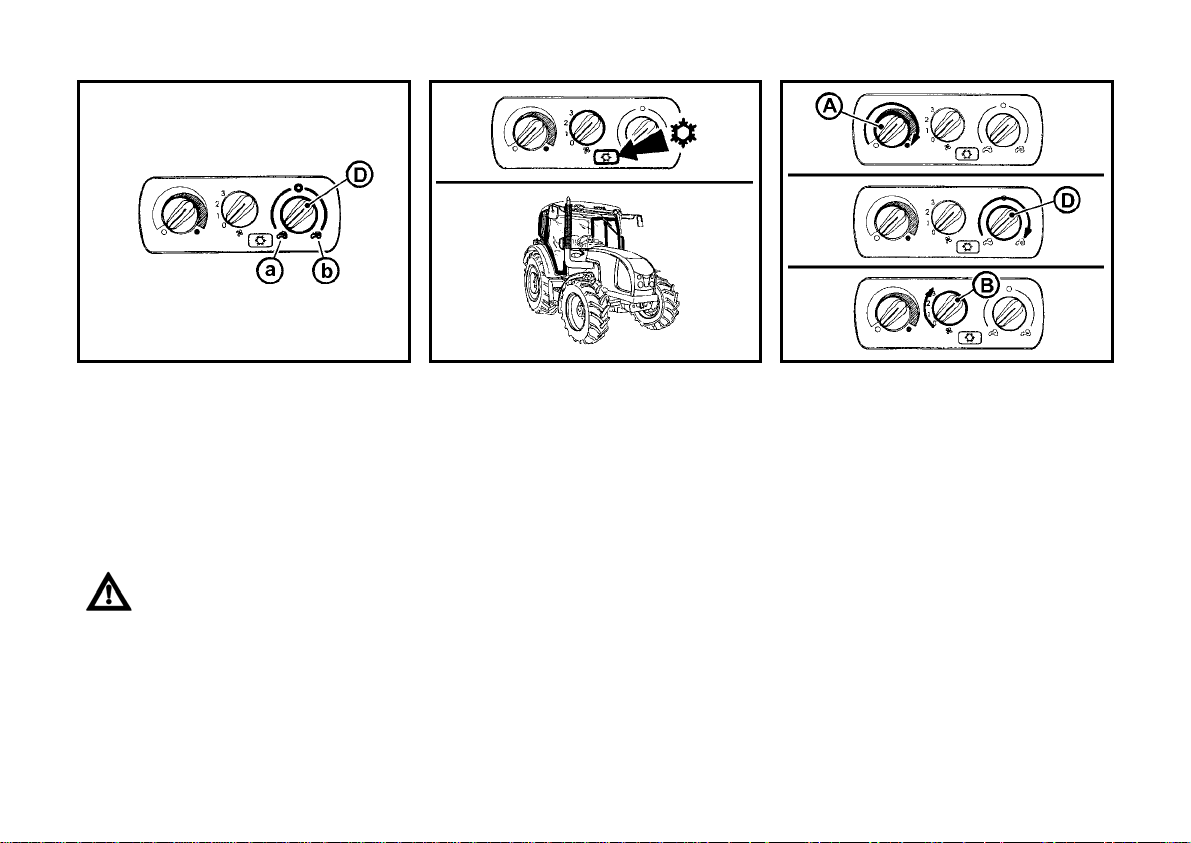
HEATING CONTROL PANEL, ∗A/C
A - Heating valve control
B - Fan control
C - Air-conditioner (A/C) switch
D - Control of air circulation in the cabin
HEATING VALVE CONTROL (A)
a - Heating valve closed
b - Heating valve open
FAN CONTROL (B)
0. Fan off
1. Fan slow run
2. Fan medium run
3. Fan fast run
39
∗AIR-CONDITION SWITCH (C)
The A/C system can be switched on/off
using the pushbutton switch with a symbol of a snow flake (C).
Pressing of the pushbutton activates the
A/C system (the snow flake symbol is
on) and next pressing the A/C system
deactivates (the snow flake symbol is
off).
GETTING TO KNOW THE TRACTOR
E120 G121 E122
CONTROL OF AIR CIRCULATION IN
THE CABIN (D)
a - Ambient (outdoor) air is sucked
through the filters into the cabin; sucking of air from inside is closed;
b - Air is sucked from inside and ex-
hausted to the cabin again (inner circulation for fast adjustment of temperature in the cabin).
Intake of air from outdoor is completely closed and there is no
overpressure in the cabin to prevent penetration of non-filtrated
air into the cabin!
Use this control position for necessary period only!
CORRECT FUNCTION OF THE
HEATING AND A/C SYSTEMS
It is necessary to create overpressure in
the cabin for correct function of heating
or air-conditioning. Therefore it is recommended to close all windows, doors
and upper cover.
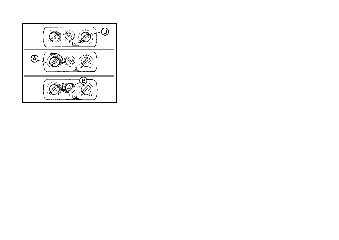
FAST WARMING-UP OF THE CABIN
SPACE
Proceed as follows:
1. Turn the heating valve control (A) to
the right (fully open heating valve).
2. Set the air circulation in the cabin
control (D) to position of inner recirculation.
3. Select the desired speed of the fans
(position 1, 2, 3) using the fan control
(B).
4. Adjust angles of the air outlets to
prevent direct blowing of persons in
the cabin.
40

GETTING TO KNOW THE TRACTOR
E123 E124
FAST COOLING OF THE CABIN
SPACE
1. Turn the heating valve control (A) to
the left.
2. Set the air circulation in the cabin
control (D) to inner recirculation.
3. Select the desired speed of the fans
(position 1, 2, 3) using the fan control
(B).
4. Switch of the A/C system using the
button (C).
5. Adjust angles of the air outlets to
prevent direct blowing of persons in
the cabin (risk of an disease due to
intensive cooling of body parts).
OPERATION OF HEATING OF AIRCONDITIONING WITH WORK OF THE
TRACTOR
In case that inner recirculation is activated, fresh air supply is closed and all the
air in the cabin becomes breathed up.
This situation may cause a feeling of fatigue.
Note: When working with the tractor, set
the control (D) to fit your individual requirements for temperature, i.e. between
positions (a) and (b) so that the fan will
suck outdoor air through the filters.
When spraying pesticides and
using the heating filter with active
carbon, the re-circulation controller should be in position “air is
drawn into from the outside” and
the fan controller should be in the
position “fan maximum work” to
create overpressure in the cabin.
41
GETTING TO KNOW THE TRACTOR
E125
WHEN THE CABIN IS COOLED
When the cabin is cooled to the desired
air temperature, we recommend:
− Set the air circulation control (D) from
position ‘b’ (air recirculation) to position
‘a’ (sucking of outdoor air).
− Carry out regulation of air temperature
with A/C switched on by partial opening/closing of the heating valve (A). In
case of this setting air, coming to the
cabin from the air outlets, is not dried
so intensively.
− Desired setting of temperature with
A/C switched on can also be carried
out by reducing speed of the fan by
setting the control (B) to position1 or 2.
42

GETTING TO KNOW THE TRACTOR
P+13N009
CONTROL PANEL ON THE CAB RIGHT PILLER
Switches placement in standard tractor (A) design
1. rear PTO shaft switch
2. front shaft switch
3. two-position switch of the windscreen wiper and washer
4. rear window wiper switch
5. switch of front working lights on cab roof
6. switch of rear working lights on cab roof
7. *rear mirrors heating switch
8. *rear window defroster switch
If a tractor is equipped with electrohydraulics EHR, the switches (1) and (2) are
placed on the external hydraulic circuit control panel (B).
43

GETTING TO KNOW THE TRACTOR
W1 F205
*TILT STEERING WHEEL
Adjusting the angle of the wheel
The angle can be adjusted by tilting the
wheel after it is unlocked by moving the
lever (1) in the direction shown by the arrow. After adjusting, lock the wheel by
pressing the lever (1) in the opposite direction than shown by the arrow.
*TILT AND TELESCOPE STEERING
WHEEL
Tilt column of the steering wheel enables
to adjust the angle and height of the
wheel.
Adjusting the height
To adjust height, pull the wheel up or
push it down after it is unlocked by moving the lever (1) in the direction shown by
the arrow. After adjusting, lock the wheel
by pressing the lever (1) in the opposite
direction than shown by the arrow.
Adjusting the angle
To adjust angle, tilt the wheel after it is
unlocked by moving the lever (2) in the
direction shown by the arrow. After adjusting, lock the wheel by pressing the
44
lever (2) in the opposite direction than
shown by the arrow.
After adjusting, tilt the lever (2)
towards the dashboard and the
lever (1) in such a way so that it
is parallel to the steering wheel
column axis.
Pushing the levers in the
direction farther from the steering
wheel column changes the
position of the levers as desired.

GETTING TO KNOW THE TRACTOR
F13BN010 F13BN011
AIR-CONDITION AND HEATING REGISTERS (A)
Positionable heating and ∗ air-condition registers, front (A), rear (B).
45
FRONT WINDSHIELD (B)
DEFROSTING
To ensure quick defrosting of the front
windshield direct the central heating outlets (1) under the angle of approx. 45°
towards the windshield. Direct the side
outlets (2) under the angle of approx. 45°
to the cab corners.
After defrosting of the front windshield direct the side outlets to the side glasses
of the doors as necessary and gradually
defrost them. After defrosting direct the
outlets in such a way that the air should
not be blown directly to the driver, but
down to the driver’s legs.

ACQUAINTANCE WITH TRACTOR
46
F13BN001

DASHBOARD
DEVICES DESCRIPTION
A - Indicators
B - Air pressure gauge
C - speedometer
F - fuel gauge
G - coolant thermometer
H - display
ACQUAINTANCE WITH TRACTOR
INDICATORS
1 - High beam lights (blue). Lights up
when high beam headlights are on.
2 - Tractor turn signal indicator (green)
3 - 1st trailer turn signal indicator (green)
4 - 2nd trailer turn signal indicator
(green)
5 - Indicator of minimum air pressure in
the brake system (red). Lights up if
the air pressure for the air brakes of
the trailer drops below the critical lim-
it, i.e. 450 kPa.
6 - Parking brake (red). Lights up when
the parking brake lever is in the “on”
position.
7 - Charging. During engine operation it
lights up in case of a charging failure.
If the engine is stopped, it must light
up. For more information see Electri-
cal installation chapter
8 - Lubrication (red). During engine op-
eration it light up if the engine oil
pressure drops below 120 to 60 kPa.
If the engine is stopped, it must light
up.
9 - Free
10 - Free
11 - Free
12 - Indicator of engagement of mul-
tiplier (green).
13 - Free
14 - Indicator of error signalization in the
system of hydrostatic steering (red)
47
With engine engaged lights up with
failure of hydrostatic steering. If engine is at standstill, it must be lit.
15 - Fuel (orange). It is lit with residue of
1/6 - 1/10 of tank volume.
16 - Indicator of PTO engagement (or-
ange) is not engaged.
17 - Engine glowing (yellow). Signals ac-
tivity of device for easing the start of
engine.
18 - Diesel particle filter control
(green) , for more see chap-
ter „Driving operation“
19 - Free
20 - Warning indicator (red). Lights up with
pressure drop under critical limit i.e.
450 kPa, with engaged parking brake,
with charging failure, with low pressure of oil in the engine or with brake
lining of the front brake wear off.
21 - Diesel particle filter control
(red), for more see “Driving
operation”
22 - Free
23 - Free
24 - Free

ACQUAINTANCE WITH TRACTOR
F13BN001
48

ACQUAINTANCE WITH TRACTOR
SELECTORS AND SWITCHES
After pressing the selected switch, the
applicable symbol and data is displayed
on the display.
25 - Battery voltage button: The voltage
value is displayed on the display
(with the resolution of 0.1 V).
26 - Button of the num ber of covered kil-
ometres (per day or since the last
reset). The number of kilometres is
shown on the display. The value can
be reset with long pressing of the
button.
27 - Button of immediate travel speed
in km.h-1, which is displayed on the
display.
28 - Free
29 - PTO button. T he rpm value with the
resolution of 10 rpm is shown on the
display.
Serves only for operation data
display
30 - The switch of hours of operation.
The information is displayed on the
display.
49

GETTING TO KNOW THE TRACTOR
F54e
DISPLAY OF PTO SPEED
By pressing the switch marked with the arrow, you will display the PTO speed in the
left and right parts of the display. It is a number of revolutions with engaged PTO
independent revolutions.
By pressing the buttons gradually, you will induced the number of PTO revolutions for
individual gears of PTO revolutions.
A - for 1000 revolutions
B - for 540 revolutions
C - for 540E revolutions
The button serves only for displaying data.
50

GETTING TO KNOW THE TRACTOR
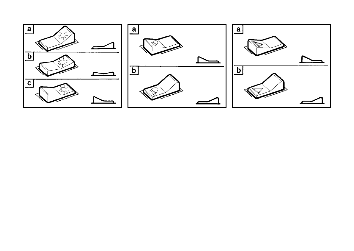
SWITCHERS, SWITCHES AND LEVERS
a - Lights switcher (off, parking lights, headlamps).
b - Switcher of low beams in the mask of the tractor
and low beams on the cabin.
∗ Optionally this switch can control the lights on
the cabin independently on the lights in the
mask of the tractor (on/off).
c - Switch of the rear fog lamp (on/off). Function of
the fog lamp is indicated by the illuminated symbol on the switch.
d - Switch of the rear working headlamp on the col-
umn of the cabin (on/off). Function of the working
headlamp is indicated by the illuminated symbol
on the switch.
e - Switch of warning lights.
f - Switch of the front driving axle. Engaged front
driving axle is indicated by the illuminated symbol
on the switch.
g - Switch of the light beacon (on/off).
h - Switch of the working lights in the mask of the
tractor (on/off). Function of the working lights is
indicated by the illuminated symbol on the switch.
i - Blinded.
j - Pushbutton of lock of the differential.
k - Engine stopping device.
l - Combined switch of direction indicators, low and
E133
high beams and acoustic horn and flash lights.
m - Ignition box.
51
GETTING TO KNOW THE TRACTOR
E134 E135 E136
LIGHTS SWITCHER (A)
a - Lighting off.
b - Marker and tail and registration plate
lights and illumination of instruments
on.
c - All consumers on as in position “b“.
In addition to this, also low or high
beams are on (according to position
of the direction indicators, headlamps and flash lights switch).
SWITCH FOR SWITCHING OVER
LIGHTS IN THE MASK AND ON THE
ROOF (B)
a - Lights on the roof off.
b - Lights on the roof on.
The switch controls lights in the mask or
on the roof of the cabin. Use the lights on
the roof of the cabin only if some implements, covering the headlamps in the
mask, are installed in the front threepoint suspension. Lighting headlamps on
the roof of the cabin are indicated by the
illuminated symbol on the switch.
The high beams may only light in the
front mask of the tractor.
SWITCH OF WARNING LIGHTS (E)
a - Warning lights off.
b - Warning lights on.
Function of warning lights is indicated by
a flashing indicator on the dashboard.
52

GETTING TO KNOW THE TRACTOR
E137 E138 E139
FRONT DRIVING AXLE SWITCH (F)
Use the front driving axle with
slipping of rear wheels to increase the tractive force of the
tractor.
a - Front driving axle off.
b - Front driving axle on.
When the tractor is laid up (the tractor is
braked, key in the ignition box in position
off) the front driving axle is switched on.
The front driving axle is switched on in
the basic position (indicator is on) and
can be switched off by the same switch
(the indicator is off).
PUSHBUTTON OF REAR
DIFFERENTIAL LOCK (J)
Press the pushbutton to switch on the
lock; the pushbutton then returns to its
original position.
Switched on lock is indicated by the illuminated symbol on the pushbutton.
Depressing brake pedals switches off
automatically the differential lock.
COMBINED SWITCH OF INDICATOR
LIGHTS, LOW AND HIGH BEAMS AND
FLASH LIGHTS (K)
a - Acoustic horn (depress the switch in
direction of the axis
b - Low beams
c - Right direction indicators
d - Left direction indicators
e - Flash lights
f - High beams
53

GETTING TO KNOW THE TRACTOR
E140
IGNITION BOX
The ignition box is located on the dashboard, see the arrow.
KEY IN POSITION "0"
Voltage to all consumers, controlled
through the key, is disconnected. The key
can be removed.
54
E141 E142
KEY IN POSITION "I"
Voltage is connected to all consumers
except the starter. The key is in this position when the engine is running. The key
cannot be removed.

GETTING TO KNOW THE TRACTOR
E143 E144 X145b
KEY IN POSITION ”II”
The key is in this position when starting
the engine; voltage is connected to the
starter and all consumers except wipers,
washers, cabin fan and A/C equipment.
After start of the engine the key returns
automatically back to position ”I”.
LEVER OF MANUAL REFULATION OF
FUEL
A - Maximum speed of the engine
B - Idle run
The lever allows setting of speed of the
engine within range A to B.
55
CONTROL OF ENGINE STOP
Pulling up the control knob causes immediate stop of the engine and it slight
turning in pulled up position locks its position.
After the engine is stopped, turn back the
control knob to its original position.
The engine cannot be started if
the control knob remains pulled
up.

GETTING TO KNOW THE TRACTOR
G146 E147 G148
PEDALS
1. Travel clutch pedal
2. Foot brake pedals, connected with a
latch
3. Pedal of foot regulation of fuel supply
LEVER OF SHIFTING GEARS
- Main shifting lever
56
SCHEME OF SHIFTING OF GEARS
Reverse can be shifted only using the
reversing lever. The scheme is attached
in the left lower corner of the windscreen.
GETTING TO KNOW THE TRACTOR
P+11NE149 G150 E151
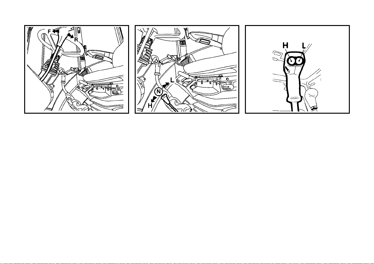
REVERSING LEVER
F – Travel forwards; lever forwards
R – Travel backward; lever backward
LEVER OF SHIFTING OF ROAD AND
REDUCED GEARS
H
Road gears
N
Neutral
L
Reduced gears
Shifting is carried out with tractor in
standstill.
57
TORQUE MULTIPLIER
The multiplier is controlled electrohydraulically using the pushbuttons located on the shifting lever.
Activation (pushbutton L) is indicated by
illumination of the indicator on the dashboard.
GETTING TO KNOW THE TRACTOR
P+11NH127b G153
SWITCHING ON OUTPUT SHAFT
DRIVE
This drive can be switched on using
switches on the right column of the cabin.
LEVER OF SHIFTING OF SPEED 540
(OR 540E) AND 1,000 RPM OF THE
REAR OUTPUT SHAFT
Shifting can be carried out when the tractor is in standstill by pulling up or pushing
down the lever.
a - 1,000 min-1(or 540E min-1)
b - 540 min
-1
∗The tractor can be equipped optionally
by 6-, 8- or 21-groove termination of the
output shaft.
58
Shifting of 540 and 1,000 (or
540E) min
less to the number of grooves on
the installed termination. Speed
of the output shaft and type of the
termination shall be chosen depending on the prescribed speed
of the aggregated machine.
-1
is possible regard-

GETTING TO KNOW THE TRACTOR
G154 E155
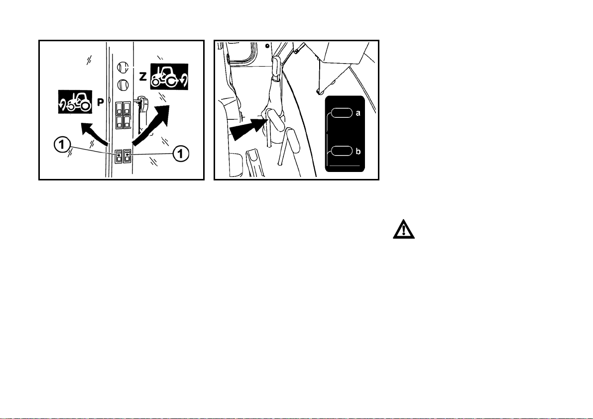
LEVER OF SWITCHING ON REAR
OUTPUT SHAF DRIVE
Shifting can be carried out when the tractor is in standstill by pulling up or pushing
down the lever.
a -
Independent rpm of the output
shaft drive-
- Speed depends on speed of
the engine.
n -
Neutral
b -
Dependent speed of the output
shaft speed through a gearbox.
- Speed depends on the engaged gear.
LEVER OF HAND BRAKE AND HITCH
FOR SINGLE-AXLE TRAILER
1. Hand brake lever.
2. Lever of the single-axle trailer hitch
control.
59

GETTING TO KNOW THE TRACTOR
E158 E159 E157
TRACTORS WITH TRAVEL SPEED
40 KM.H
All types of tractors with driven front axle
that includes brakes in reducers of front
wheel can be equipped with travel speed
40 km.h
-1
-1
.
FUEL TANK
The fuel tank is located on the right side
of the tractor. The volume of this plastic
tank is 150 litres.
Do not step onto the fuel tank!
DRAINING PLUG OF THE FUEL TANK
A plug for draining of dirt from the fuel
tank is installed in its bottom.
60
BATTERY DISCONNECTOR
Disconnect the battery immediately using the battery disconnector in case of a long-term standstill, repairs, fault or accident.
The battery disconnector is located on
the left side of the tractor, in front of the
cabin.
a - Battery connected
b - Battery disconnected

Before a drive with the new tractor get to know how to shift
gears and try individual positions
of the shifting lever when the
engine is stopped.
During normal operation and before you set up, make sure that
the technical condition ensures
safe operation of the tractor.
DRIVING
Page
Before you start the engine.......................................................................................63
Starting the engine.................................................................................................... 63
In case the engine does not start..............................................................................64
Indications of faults in the heating system.................................................................64
Manipulation with the starter.....................................................................................64
Immediately after starting..........................................................................................65
Warming-up of the engine.........................................................................................65
∗Heater of cooling fluid..............................................................................................66
Starting of the engine using heater of cooling fluid....................................................66
Diesel particle filter....................................................................................................67
Diesel particle filter – system failures signalization ................................................... 68
Diesel particle filter - failure codes ............................................................................68
Diesel particle filter - regeneration.............................................................................69
Shifting of gears........................................................................................................70
Reversing lever.........................................................................................................70
Shifting of road and reduced gears...........................................................................70
Shifting from lower to higher gear ............................................................................. 71
Shifting from higher to lower gear .............................................................................71
Torque multiplier .......................................................................................................72
Indication of function of the multiplier........................................................................ 72
Moving off..................................................................................................................73
Driving uphill..............................................................................................................74
Driving downhill.........................................................................................................74
Differential lock..........................................................................................................75
Control of front driving axle .......................................................................................75
Driving with engaged front driving axle .....................................................................75
Foot brakes...............................................................................................................76
Air brakes of trailers and semi-trailers.......................................................................76
Warning indication of air pressure drop.....................................................................76
Single-hose and double-hose brakes........................................................................77
Single-hose brakes ...................................................................................................77
Double-hose brakes.................................................................................................. 77
61

DRIVING
Page
Trailer hydraulic brakes............................................................................................. 78
Connection and disconnection of quick couplings of the trailer hydraulic brakes...... 78
Stopping the tractor - hand brake.............................................................................. 79
Stopping the engine.................................................................................................. 79
Leaving the tractor.................................................................................................... 79
Warning indication of a hydrostatic steering fault...................................................... 80
Important warnings ................................................................................................... 80
62

DRIVING
G201
BEFORE YOU START THE ENGINE
Before you start the engine, make
sure:
1. If the tractor is properly
braked.
2. If the main shifting lever is in
neutral position.
Unless the clutch pedal is depressed, the
engine cannot be started, as the start
security switch is not closed.
Note: Before starting of the engine it is
advisable to pressurise the fuel system
by several strokes of the manual feeding
fuel pump.
P+11NG202
STARTING THE ENGINE
1. Put the key in ignition - ”0” position.
2. Depress the clutch pedal.
3. Move the gear lever to the neutral position.
4. Turn the key to “I“ position. The glow
plug indicator illuminates.
5. Wait till the glow plug indicator goes
out (the time depends on the temperature of the liquid coolant).
63
P+11NG203
If the glow plug indicator does not
illuminate but flashes, there is an
error of the ignition system (Ignition system error signals chapter). Have the error repaired in a
specialized service station.
6. When the indicator goes out, turn the
key immediately (do not wait for
longer than 5 sec. at maximum) to “II“
position (start).
7. After ignition, release the key immediately, it automatically turns back to ”I”
position. Do not extend th e starting
process to more than 15s.
8. After ignition, decrease the amount of
fuel gradually.
G204 G205 G206
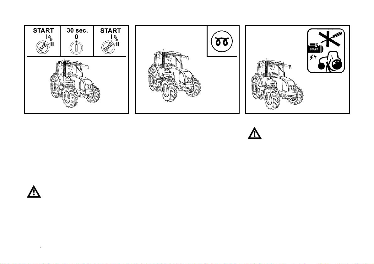
IN CASE THE ENGINE DOES NOT
START
Turn the ignition key back to position ”0”,
wait for 30 seconds and repeat starting.
It is permitted to execute 6 starting cycles (15 sec starting and 30 sec pause).
Next starting of the engine is permitted
after the starter is cooled down to the
ambient temperature.
Never activate the starter if the
tractor is stopping. The starter
should be exposed to a risk of
damage.
DRIVING
INDICATIONS OF FAULTS IN THE
HEATING SYSTEM
A fault of the heating system is indicated
by a flashing indicator of heating.
- Flashing of the indicator in second intervals during standstill of the engine
indicates heating in an emergency regime as at low temperatures regardless to temperature of the cooling fluid.
- Flashing of the indicator two times per
second during standstill of the engine
indicates stopped (non-functioning)
heating.
- Permanent flashing of the indicator of
heating during run of the engine indicates a fault of the regulator of heating, whilst heating continues. The fault
shall immediately be eliminated to prevent discharge of the battery.
64
MANIPULATION WITH THE STARTER
It is forbidden to start the engine using short-circuited
starter terminals!
The tractor can only be started
from the driver’s seat!
With any manipulation of repair of
the starter it is necessary to
disconnect the minus pole of the
battery and move all levers including shifting of the output shaft
to neutral position! The starter
contacts are protected by caps.

DRIVING
G207
IMMEDIATELY AFTER STARTING
After starting of the engine adjust
speed to 800-1000 min
the engine running without loading for approx. 2 minutes.
In this period perform checks of lubrication and recharging of the battery (the
indicator shall be off) and other functions
providing proper run of the engine. The
time of run without loading shall be observed, particularly in winter period.
-1
and let
WARMING-UP OF THE ENGINE
Further warming-up of the engine should be performed during driving.
Warming-up of the engine using long idle run or sudden increase of speed is
harmful for the engine.
Unless temperature of cooling fluid reaches 45 °C, do not exceed speed of
the engine 2000 min
-1
.
65
G208

DRIVING
E209 E210a
∗HEATER OF COOLING FLUID
It is installed on the right side of the engine block.
Power: 1000W
Voltage: 220V
STARTING OF THE ENGINE USING HEATER OF COOLING FLUID
Heating of cooling fluid facilitates starting of the engine at low temperatures. Power
supply installation and its protection against dangerous contact shall be made according to the applicable regulations.
1. First insert the plug into the heater.
2. Then connect the heater to the power supply mains with voltage 220V.
For reduced wearing of the engine with its starting at low temperatures, the manufacturer recommends use of the heater. Time of heating depends on the ambient temperature (1 to 2 hours before the expected starting is sufficient).
After end of heating first disconnect the device from the power supply mains
and then unplug the cable from the heater!
Risk of injury from electric shock!
It is necessary to instruct operators of the tractor and ensure regular revisions of the cooling fluid heater including power supply cable according to the applicable standards of the country where the tractor is operated, at least before each winter season.
66

DRIVING
FH12N056
DIESEL PARTICLE FILTER
The exhaust system of a tractor is equipped with a diesel particle filter which
serves for cleaning exhaust fumes. Solid particles (carbon particles) are col-
lected and burned in diesel particle filter which originate by burning diesel.
The activity of diesel particle filter is signalized by a pair of controls (green and red)
on the dashboard.
Diesel particle filter system failures with engine running are signalized by a lit red
control on the dashboard and then with an acoustic signal.
A short-term turning-on of the red control without a subsequent acoustic sig-
nal does not signalize a failure.
.
Clogging of diesel particle filter automatically regenerates the exhaust gases temperature with higher engine load.
The conditions suitable for diesel particle filter regeneration are signalized by a lit
green control on the dashboard with engine running.
When operating tractors with engines equipped with diesel particle filter, avoid
long-term operation or low engine load.
67

DRIVING
FH12N075
DIESEL PARTICLE FILTER – SYSTEM FAILURES SIGNALIZATION
Failures in diesel particle system failure are signalized by a red control light-
ing up on the dashboard with engine running and subsequently by an acous-
tic signal.
If the failure is not removed, it is signalized with any following starting of the engine
The code of failure us displayed on a display (1) of the displaying unit which is accessible after removing the right cover of the steering console.
The failures are displayed on display (1) in a form of E: double-figured code of failure
For example: E:36, number 36 representing the code of failure
If failure is not signalized, operation data of diesel particle filter system are displayed
on the display.
The acoustic signal can be turned off by the button (2). If the failure has not been removed, the acoustic signal is active with repeated staring of the engine and can be
turned off again by the button (2).
If the key is in switchbox in “I” position and the engine is not started, approximately
ten minutes later the diesel particle filter system starts signalizing a failure. Switch the
key to “0” position and start the engine. The code of failure on the display E:32 or
E:33.
68
DIESEL PARTICLE FILTER FAILURE CODES
Failure
code E:
11, 12, 21,
22, 23, 31,
34, 35, 37,
38, 41, 42,
51, 52, 61,
62
32, 33, Switch the key to “0” posi-
36 Regenerate diesel particle
Operator´s activity
The tractor can be worked
without any limitations, after terminating your work,
contact authorized service
and report the code of
failure.
tion and start the engine.
filter

DRIVING
FH12N076
DIESEL PARTICLE FILTER - REGENERATION
During the operation of a tractor, diesel particle filter is clogged by solid particles
originating in engine run when burning fuel. Clogged diesel particle filter automatically regenerates the temperature of exhaust fumes with higher load of the engine.
When operating the tractor with low load of the engine , e.g. with long-term operation
on idle run, there is a partial clogging of diesel particle filter. This condition is signalized with the engine run by a lit red control of diesel particle filter, and followingly also
by acoustic signal and on the display of displaying unit of diesel particle filter by failure code
E:36
If this situation occurs, increase the load of engine and continue working until red
control of diesel particle filter switches off and acoustic signal does not stop.
By increasing the engine load, the temperature of exhaust fumes increases and the
solid particles which clog diesel particle filter burn The conditions suitable for diesel
particle filter regeneration are signalized by a lit green control on the dashboard. Depending on the temperature of exhaust fumes and the degree of diesel particle filter
clogging, regeneration can take up to thirty minutes.
When regeneration is achieved,
notification information signalization goes out (error 36). If this signalization does not go out, repeat
this procedure. If it still does not go
out, you need to address an authorized service.
Increased load of engine shall be
work with a tractor at higher engine
revolutions (1 800 RPM) with connected tools, power intake via PTO
shaft or outer hydraulic circuit.
69

DRIVING
E211 P+11NE212 G150
SHIFTING OF GEARS
The tractors are equipped with a 4-speed
synchronised gearbox, torque multiplier,
reversing and two-stage reduction.
The 4-speed gearbox is operated using
the main shifting lever with pushbuttons
to control of the torque multiplier. Movement of the tractor forward and backward
is selected by the reversing lever.
REVERSING LEVER
Reversing lever selects direction of
movements of the tractor (forward,
backward).
F – travel forward (16 speeds)
R – travel backward (16 speeds)
The reversing gearbox includes 16 reverse speeds that are approximately the
same as the forward speeds. Therefore
consider carefully when shifting a reverse gear for the given character of
your work.
Perform reverse shifting with
clutch pedal depressed and tractor in standstill.
70
SHIFTING OF ROAD AND REDUCED
GEARS
H – road speeds
N – neutral
L – reduced speeds
Shifting of gears of the main gearbox
with reduced speeds is the same as with
road speeds.
Shifting using the lever of road
and reduced speeds is only possible when the tractor is in standstill.

DRIVING
E214a E215a
SHIFTING FROM LOWER TO HIGHER
GEAR
Tread on the clutch pedal (the clutch is
disengaged); at the same time release
the accelerator pedal and shift the desired higher gear. Release smoothly the
clutch pedal (the clutch is engaging) and
at the same time increase speed of the
engine.
Note: It is advisable to shift from a lower
to a higher gear with double treading on
the clutch pedal to increase service life
of the synchronisation device.
SHIFTING FROM HIGHER TO LOWER
GEAR
Tread on the clutch pedal and move the
shifting lever through neutral position to
a lower gear.
Note: It is advisable to shift from a high-
er to a lower gear with increasing of
speed of the engine in the neutral position to increase service life of the synchronisation device.
71

DRIVING
E216 E217
TORQUE MULTIPLIER
The two-stage multiplier is standard
equipment of all types of tractors.
Selection of individual stages of the twostage multiplier is operated by two
pushbuttons on the main shifting lever
head.
Selection is performed by pressing the
respective pushbutton without treading
on pedal of the travel clutch. Shifting individual stages of the multiplier is automatic even with loading of the engine.
Shifting of the torque multiplier stages:
H
– increase of travel speed
L
– decrease of travel speed
Note: When starting or stopping the engine there is always shifted automatically
the stage H.
INDICATION OF FUNCTION OF THE
MULTIPLIER
Engagement of the multiplier (decrease
of travel speed) is indicated by a light indicator on the dashboard.
72
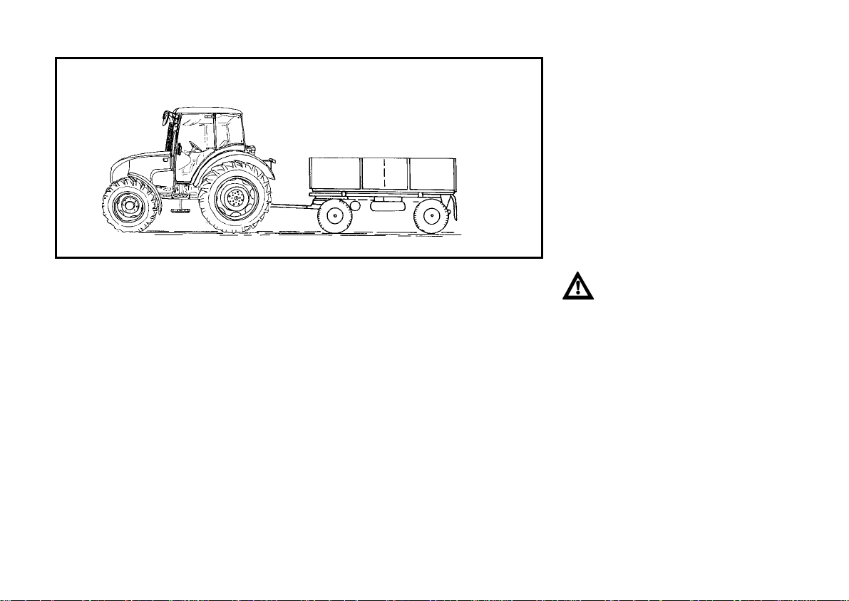
DRIVING
G218
MOVING OFF
1. Tread on the clutch pedal.
2. Move the main shifting lever to neutral position.
3. Start the engine.
4. Adjust speed of the engine to 800 min
5. Choose road or reduced speeds.
6. Move the reversing lever to the desired direction of travel (forward or backward).
7. Shift the suitable gear for moving off the tractor.
8. Increase slightly speed of the engine.
9. Make ready the hand brake for its release.
10. Release the clutch pedal just till the engagement point; with simultaneous in-
creasing of speed of the engine continue in releasing of the clutch pedal.
11. Release completely the hand brake.
12. Begin move off smoothly and slowly.
-1
.
Very fast moving off may cause
overloading of the driving mechanism, increased consumption of
fuel, excessive wearing of tyres
and damage to the load. Moving
off with engaged 1
be used only when driving with a
heavy trailer uphill and in difficult
terrain.
st
gear should
73

DRIVING UPHILL
Shifting from a higher to a lower
gear when driving uphill should
be performed soon enough to
prevent a drop of speed of the
engine under 800 min
ing leading to stop of the engine
due to its overloading.
-1
and driv-
DRIVING
G219 G220
DRIVING DOWNHILL
Driving downhill without shifted
gear is forbidden. When driving
downhill for a longer time, shift as
low gear as steep the road is. If
possible, shift a lower gear before
you start driving downhill.
Note: You can go downhill safely with
the same gear engaged as you should
shift it when driving uphill.
74

DRIVING
G221 E222 G223
DIFFERENTIAL LOCK
The differential can be locked by pressing a switch that returns back to its original position after it is released.
Locking of the differential is indicated by
an illuminated symbol on the switch.
Depressing of the brake pedals unlocks
automatically the differential.
Do not use the differential lock
when driving through road bends.
CONTROL OF FRONT DRIVING AXLE
The front driving axle is engaged in the
basic position.
Engagement of the front driving axle is
indicated by an illuminated symbol on
the switch.
It can be disengaged using a switch on
the dashboard.
a - Front driving axle engaged
b - Front driving axle disengaged
In case of a drop of air pressure
in the compressed air system of
the tractor the front driving axle is
engaged automatically.
75
DRIVING WITH ENGAGED FRONT
DRIVING AXLE
Use the front driving axle with
slipping of the rear wheels to increase the traction force of the
tractor. It is permitted to engage
the front driving axle on roads
and hard surfaces up to 15 km/h
(travel with engaged front driving
axle causes increased wearing of
front tyres).
Permanent engagement of the front driving axle is permitted if there is a farming
mechanism attached to the front suspension. This condition is mentioned in
the instructions manual to the respective
mechanism.
Maximum permitted speed when driving
with these attachments is 15km.h-1.
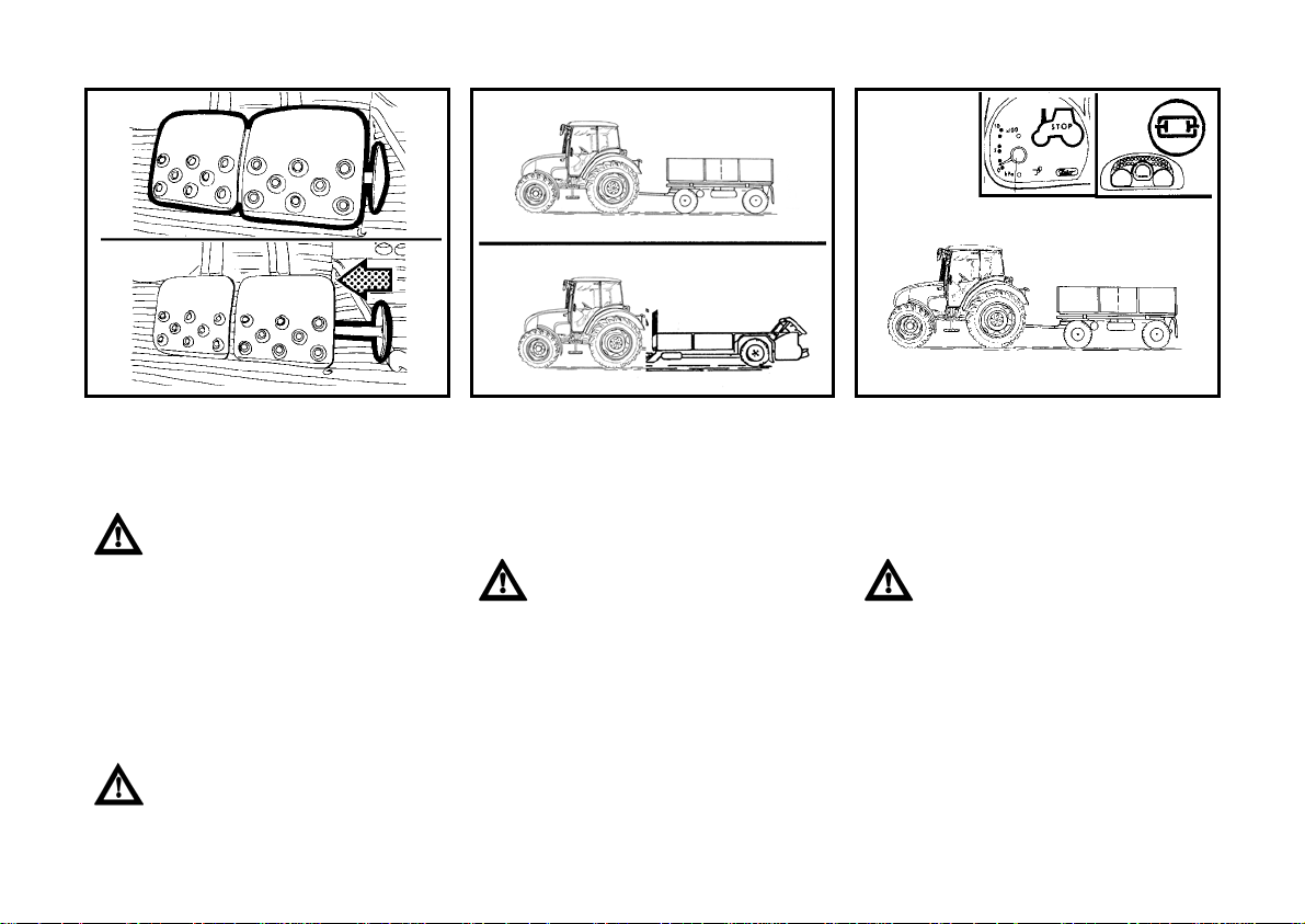
DRIVING
E224 G225 G226
FOOT BRAKES
The foot brakes are disk wet type, hydraulic-controlled, with two pedals and
automatic pressure balancer.
During travel both pedal have to
be coupled with a latch. Use uncoupled pedals for barking of the
right or left wheel only when
working in terrain and on a field
at low travel speeds.
Note: When driving from a steep
downslope with a trailer or semi-trailer
equipped with air or hydraulic brakes it is
necessary to start braking by foot brake
already from beginning of the slope!
With braking by one brake pedal the trailer brakes are not
activated!
AIR BRAKES OF TRAILERS AND
SEMI-TRAILERS
Air brakes of trailers (semi-trailers) and
brakes of the tractor are designed so that
braking effects of both vehicles are synchronised.
When driving with a trailer or
semi-trailer the foot brake pedals
shall be coupled and secured by
a latch!
With braking by one brake pedal the trailer air brakes are not
activated.
Note: In case of a drop of pressure the
transfer valve disables the secondary
consumers (differential lock, disengagement of the front driving axle).
76
WARNING INDICATION OF AIR
PRESSURE DROP
Decrease of air pressure under 450kPa
is indicated by a red lamp and red symbol of a tractor with a sign STOP on the
dashboard.
In case of a pressure drop in the
compressed air system under
450kPa the tractor with braked
trailer or semi-trailer may not
travel until air pressure increases.
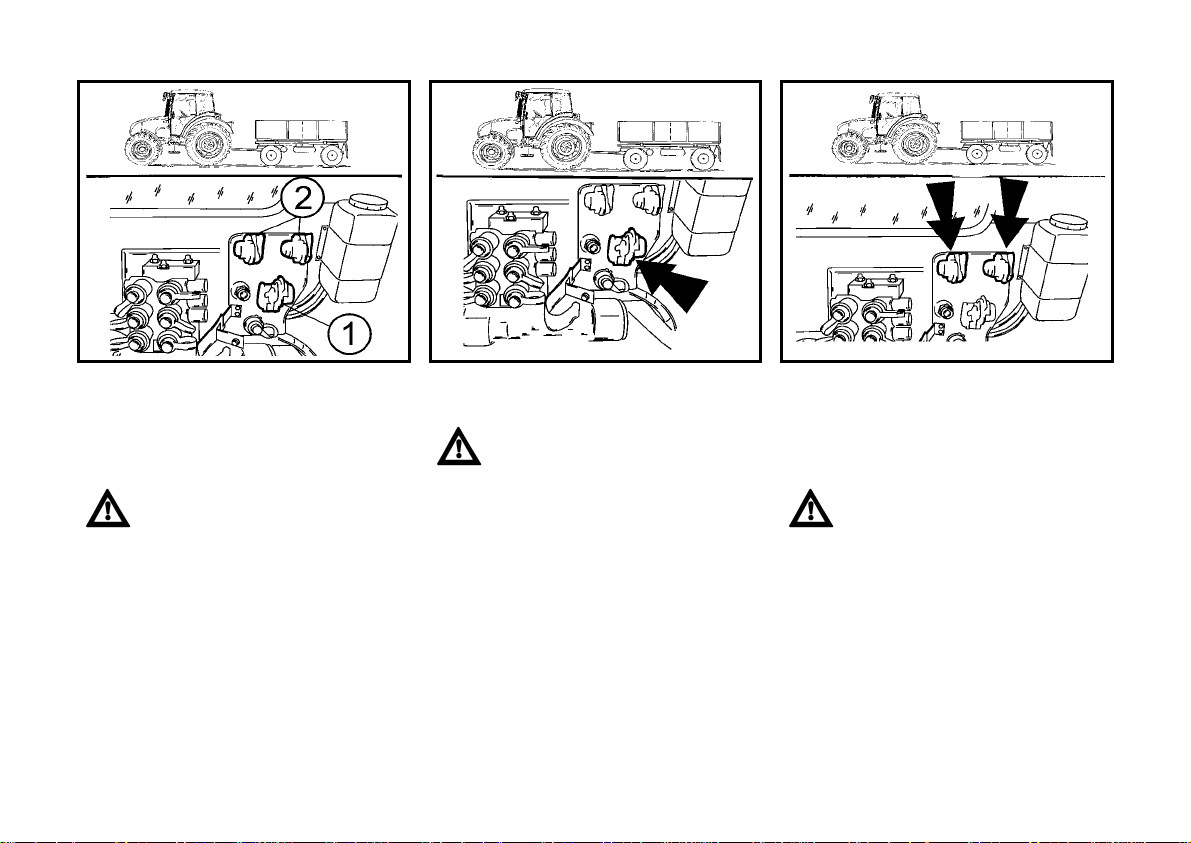
DRIVING
P11NX227 P11NX228 P11NX229
SINGLE-HOSE AND DOUBLE-HOSE
BRAKES
1. Coupling head of single-hose brakes.
2. Coupling heads of double-hose
brakes.
The coupling heads shall be
covered with lids after
disconnecting or when a trailer
(semi-trailer) is not coupled.
SINGLE-HOSE BRAKES
The lid is marked by black colour.
When a trailer (semi-trailer) with
maximum permitted weight approved for the given type of tractor is coupled, the maximum
permitted speed of the vehicle
train is 30km.h
The maximum permitted speed of
the vehicle train is given by the
maximum permitted speed of the
slower vehicle of the train.
-1
!
77
DOUBLE-HOSE BRAKES
The lid of the left head is marked by yellow colour (braking branch), the lid of the
right head is marked by red colour (filling
branch).
When a trailer (semi-trailer) with
maximum permitted weight approved for the given type of tractor is coupled, the maximum
permitted speed of the vehicle
train is 40km.h
The maximum permitted speed of
the vehicle train is given by the
maximum permitted speed of the
slower vehicle of the train.
-1
!
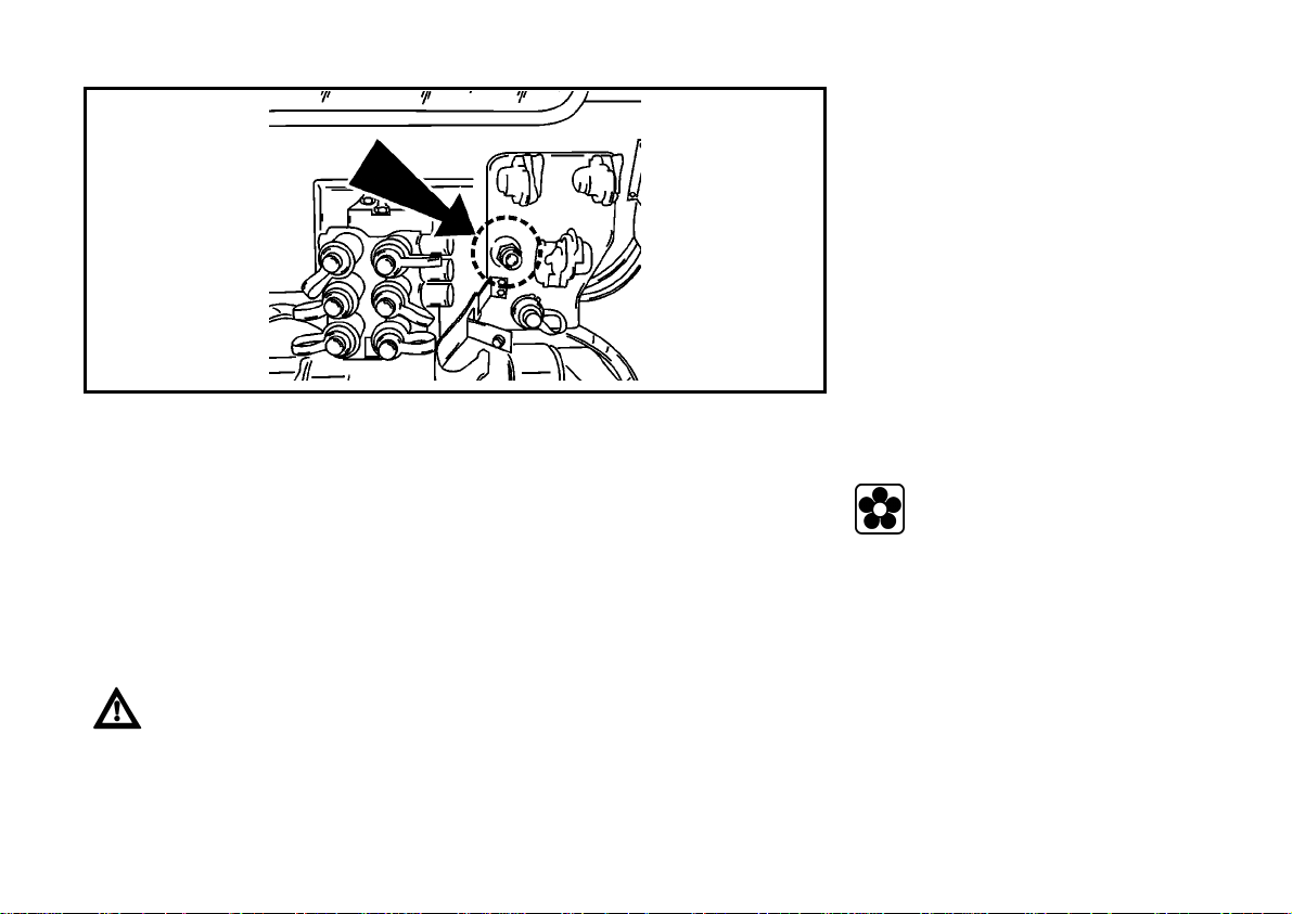
DRIVING
P11NE231
TRAILER HYDRAULIC BRAKES
Connect the trailer or semi-trailer hydraulic brakes with the quick coupler marked with
an arrow.
The control of the trailer (semi-trailer) hydraulic brakes and the control of the tractor
brakes ensure synchronized braking effect of both the vehicles. Working pressure is
enforced by oil supplied from the hydraulic gear-type pump that works permanently.
The trailer brake control valve is controlled by brake fluid pressure from the main
brake cylinders depending on force that influences the brake pedal. Upon maximum
pressing down the brake pedal, pressure on the coupling head should be 12 - 15
MPa. The trailer brake valve prefers the brake function to the hydraulic function.
In the event of shocks when you press down the brake pedal, you have to bleed the
hose from the brake valve to the quick coupling.
When driving with trailer, the brake pedals should be connected and safeguarded with a lock!
When braking with one brake pedal, the trailer hydraulic brakes are out
of operation.
CONNECTION AND DISCONNECTION
OF QUICK COUPLINGS OF THE
TRAILER HYDRAULIC BRAKES
When connecting and disconnecting the quick couplings you
should be aware of the rest of oil
that is kept in the quick coupling
plug or socket.
To protect environment you have
to remove the oil residues after
each disconnection of the quick
couplings with a textile rag.
78

DRIVING
G232 G233 G234
STOPPING THE TRACTOR - HAND
BRAKE
Under normal conditions stop the tractor
slowly. Shortly before stopping:
1. Tread on the clutch pedal and brake
the tractor by the foot brake.
2. Move the main shifting lever to neutral
position.
3. With each stop secure the tractor us-
ing the hand brake against spontaneous moving off. Application of the
hand brake is indicated by a light on
the dashboard.
STOPPING THE ENGINE
After stopping the work, if the engine
was fully loaded, it is necessary to ensure to let the engine cooled down.
1. Before you stop the engine, reduce its
speed to 800-1000 min
running without loading for approx. 5
minutes.
2. Move the lever of manual regulation
of fuel supply to position MIN.
3. Pull out the controller of stopping of
the engine (stopping device) and turn
it slightly; push it back after the engine
stops.
4. When the engine stops, the ignition
key can be turned from position "I" to
"0" (only if the engine is stopped; the
battery recharging indicator shall be
on).
79
-1
and let it
LEAVING THE TRACTOR
Before you leave the tractor with safety
cabin, do not forget remove the key in
position “0“from the ignition box (in positions I and II the key cannot be pulled
out).
The tractor shall be secured
against spontaneous moving off:
1. Engine switched off.
In case that the tractor is standing on a
slope, its wheels shall be wedged.
Lock the cabin.
Note: When the engine is stopped, the
front driving axle is engaged automatically.
st
2. 1
gear engaged.
3. Hand brake applied.

DRIVING
E235 G236
WARNING INDICATION OF A
HYDROSTATIC STEERING FAULT
A fault of the hydrostatic steering pump
occurs when pressure of oil drops under
120kPa; it is indicated by the respective
symbol on the dashboard.
Note: When starting the engine or at low
speed of the engine the indicator may
flash; if the indicator light disappears after starting of increase of speed of the
engine, this does not indicate any fault.
The system is OK.
IMPORTANT WARNINGS
In case that indicator of lubrication, battery recharge or a fault of the hydrostatic
steering is on during normal operation of
the tractor, stop the tractor immediately,
stop the engine and contact a specialised repair shop. This prevents a serious
damage or breakdown of the tractor.
80

RUNNING-IN THE TRACTOR
General principles for running-in a new tractor in the course of first 100 operating
hours......................................................................................................................... 82
In the course of first 100 operating hours..................................................................82
From 100 operating hours.........................................................................................83
Page
81

RUNNING-IN THE TRACTOR
G251 G252
GENERAL PRINCIPLES FOR RUNNING-IN A NEW TRACTOR IN THE COURSE
OF FIRST 100 OPERATING HOURS
In the course of first 100 operating hours:
- do not load the engine excessively;
- avoid run with partial load of the engine;
- avoid excessive idle run time;
- check frequently level of oil in the engine (increased consumption of oil within
this period is normal);
- checks screwed joints, in particular supporting parts of the tractor;
- remedy immediately all found faults; this prevents consequent damages and/or
threats to safety of operation;
- follow also the same procedure after overhaul of the tractor
IN THE COURSE OF FIRST 100
OPERATING HOURS
- perform running-in in normal traffic;
- retighten nuts of front and rear wheels
including connection flange/rim by the
prescribed torques.
82

RUNNING-IN THE TRACTOR
E256
FROM 100 OPERATING HOURS
After running-in you can work with the
tractor without any limitation.
Operating values of engines of tractors:
Recommended operating speed
Idle run 800±25 min-1
Operating oil pressure
Oil pressure at idle
run
Max. temperature of
cooling fluid
1400-2300 min
0.2-0.5 MPa
min. 0.05 MPa
106 °C
-1
83

NOTES
84

Before a drive make sure that the
technical condition ensures safe
operation of the tractor.
In case that a trailer or implement is
coupled, verify its coupling and proper
fixing of the load. Never get out of the
tractor to couple a trailer yourself. Pay
also attention to your assistant.
TRANSPORT USE
Front hook.................................................................................................................86
Multi-level quick-adjustable hitch CBM...................................................................... 86
Height adjustment and dismounting of the multi-level hitch CBM..............................86
Automatic hitch of the multi-level hitch device CBM..................................................87
Modular system of hitches for trailers and semi-trailers............................................87
Bracket Module of pivoted pull bar............................................................................ 87
Pivoted pull bar ......................................................................................................... 87
Bracket Module of pivoted pull bar with fixed pin ...................................................... 88
Bracket module with ball ø 80...................................................................................88
∗Towing bar...............................................................................................................88
Coupling of a single-axle trailer.................................................................................89
Uncoupling of a single-axle trailer .............................................................................89
Hitch CBM for single-axle trailers..............................................................................89
Coupling with a trailer or semi-trailer......................................................................... 90
Hook of the mounting for a single-axle trailer............................................................90
Maximum permitted vertical static loading of hitches for trailers and semi-trailers.... 91
Page
85

TRANSPORT USE
E301 E302 E303
FRONT HOOK
It can only be used for towing of the tractor without trailer or other accessories attached.
Use a towing bar or rope to extricate the tractor.
Never use chains! Risk of a lethal
injury with rupture of the chain!
It is forbidden to use axles of the
tractor (individual travel wheels)
as a winch with extrication of the
stuck tractor.
MULTI-LEVEL QUICK-ADJUSTABLE
HITCH CBM
It is used for coupling of double-axle of
light single-axle trailers. The guide hitch
is height-adjustable. When working with
farming mechanisms it is necessary to
adjust height of the hitch or dismount it.
86
HEIGHT ADJUSTMENT AND
DISMOUNTING OF THE MULTI-LEVEL
HITCH CBM
Moving of the control lever in direction of
the arrow to position (1) unlocks the lever, consequent moving to position (2)
engages the arrestment pins (3); this releases the multi-level hitch and its height
can be adjusted or the hitch can be dismounted. After release of the lever from
position (2) the arrestment pins (3) are
disengaged and the lever returns automatically to its initial position.

TRANSPORT USE
E304 E305 E306
AUTOMATIC HITCH OF THE MULTILEVEL HITCH DEVICE CBM
Moving of the lever (1) in direction of the
arrow (a) slides the pin (2) into the upper
position that is indicated by the extracted
warning indicator (3), see fig. (A).
After sliding the hitch onto the pole eye
the pin slides automatically into the trailer pole eye. The hitch pin (2) can be
engaged manually by sliding the lever (1)
in direction of the arrow (b). Engagement
of the pin is indicated by the retracted
warning indicator (3), see fig. (B).
After connecting the trailer it is
always necessary to check
whether the warning indicator (3)
is retracted as shown on fig. (B).
MODULAR SYSTEM OF HITCHES FOR
TRAILERS AND SEMI-TRAILERS
Types of modules:
Fig. (B) – Pivoted pull bar bracket.
Fig. (C) – Pivoted pull bar bracket with
fixed pin.
Fig. (D) – Bracket with ball ø 80.
Dismounting – fig. (A):
1. Dismount the locking screw (1).
2. Secure the module against fall, unlock and dismount the pins (2).
3. Slide out the module from the bracket
downward.
Mounting is performed in reverse order.
87
BRACKET MODULE OF PIVOTED
PULL BAR
The bracket module of the pivoted pull
bar is located in the multi-level hitch
bracket.
PIVOTED PULL BAR
Dismounting:
1. Unlock and dismount the pins (1).
2. Pull out the pivoted pull bar in direction of the arrow.
Mounting is performed in reverse order.

TRANSPORT USE
E307 E308 E312
BRACKET MODULE OF PIVOTED
PULL BAR WITH FIXED PIN
Mounting and dismounting of the pivoted
pull bar should be performed as described in the chapter “Pivoted pull bar”.
Coupling the pole eye to the fixed pin (3):
1. Unlock and dismount the pin (1).
2. Lift the locking wedge (2) in direction
of the arrow.
3. Couple the pole eye to the fixed pin
(3).
4. Return the locking wedge (2) to its initial position and lock it using the pin
(1).
BRACKET MODULE WITH BALL Ø 80
The bracket with ø 80 is used only for coupling of trailers with a
coupling device designed for
balls ø 80.
Fig. (A) – Unlocking of the hitch:
Moving of the lever (1) in direction of the
arrow slides off the locking wedge (2).
Fig. (B) – Locking of the hitch. (B):
Moving of the lever (1) in direction of the
arrow slides in the locking wedge (2).
88
∗TOWING BAR
Height of the towing bar can be adjusted
within entire extent of the adjustable
height. Only those farming mechanisms
can be attached to the towing bar that
load it permanently downwards.
When working with the towing bar
dismount the multi-level hitch and
pivoted pull bar.
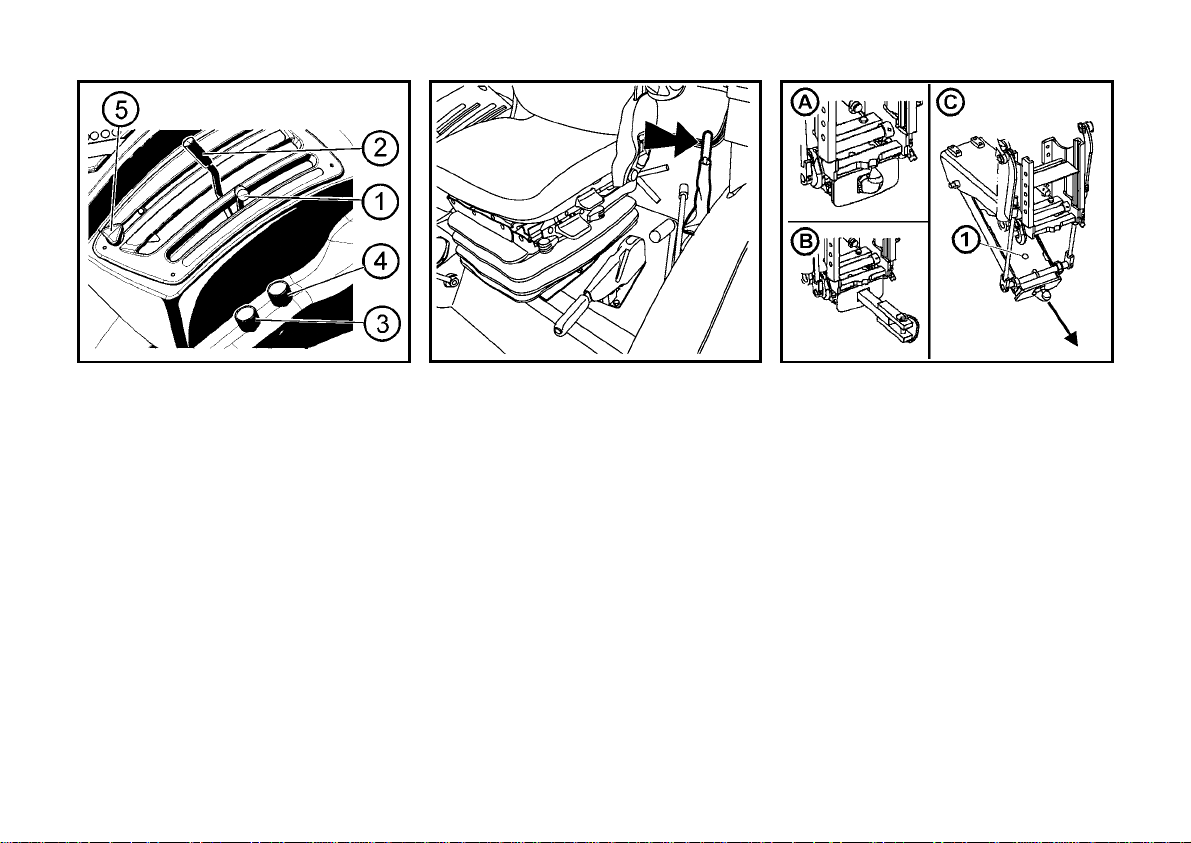
TRANSPORT USE
P+11N003 E311 E309
COUPLING OF A SINGLE-AXLE
TRAILER
Coupling can be performed using the inner hydraulic circuit lever (2). The hitch
hook with the trailer pole eye is lifted hydraulically to the position where the supporting hooks click under pins of the
hitch carrier. The lifting arms of the hydraulic device then shall be lowered to
lock the supporting hooks onto the carrier pins; the telescopic pull rods shall
not be under any tension.
UNCOUPLING OF A SINGLE-AXLE
TRAILER
This can be performed after slight lifting
of the hitch by the inner hydraulic circuit
lever. Move the control lever backwards.
The lever is located on the left side of the
driver’s seat. Lower the hitch using the
inner hydraulic circuit lever and disconnect the trailer pole eye.
89
HITCH CBM FOR SINGLE-AXLE
TRAILERS
The hitch for a single-axle trailer can be
equipped with a hook (A) that is designed for coupling of single-axle trailers
having poles according to the standard
ISO 5692 (inner diameter of the eye
50mm and height of the eye 30mm) or
pivoted pull bar (B).
The coupling hook is lowered and lifted
hydraulically using length-adjustable telescopic pull rods.
Replacement of the hook for the pivoted
pull bar (C):
1. Lower the hitch.
2. Unlock and remove the pin (1).
3. Remove the hook in direction of the
arrow.
The pivoted pull bar is mounted in reverse order.

G313 G900
COUPLING WITH A TRAILER OR
SEMI-TRAILER
The tractor can be coupled only with a
tractor trailer after matching of operating
brakes of the tractor and pneumatic or
hydraulic brakes of the trailer. In case of
coupling with a semi-trailer the static
loading of the rear axle of the tractor may
not exceed the maximum permitted value.
TRANSPORT USE
HOOK OF THE MOUNTING FOR A
SINGLE-AXLE TRAILER
The hook of the mounting for a singleaxle trailer is located in the bracket on
the left-hand side of the cabin back wall.
90

TRANSPORT USE
MAXIMUM PERMITTED VERTICAL STATIC LOADING OF HITCHES FOR TRAILERS AND SEMITRAILERS
Permitted
vertical
static
loading
2,000kg
Diameter
of hitch
pin
38mm
Hitch type
Permitted
vertical
static
loading
2,000kg
Diameter
of hitch
pin
31mm
Hitch type
Hitch class D2 Hitch class C
Maximum weight of a coupled braked trailer or semi-trailer shall not exceed the value given on
the type plate of the tractor and value given in the MOT certificate of the vehicle. Hitch of class C:
max. weight of the trailer 6,000kg. Hitch of class D2: max. weight of the trailer 14,000kg.
2,000 kg
43mm
91
1,500 kg
28mm
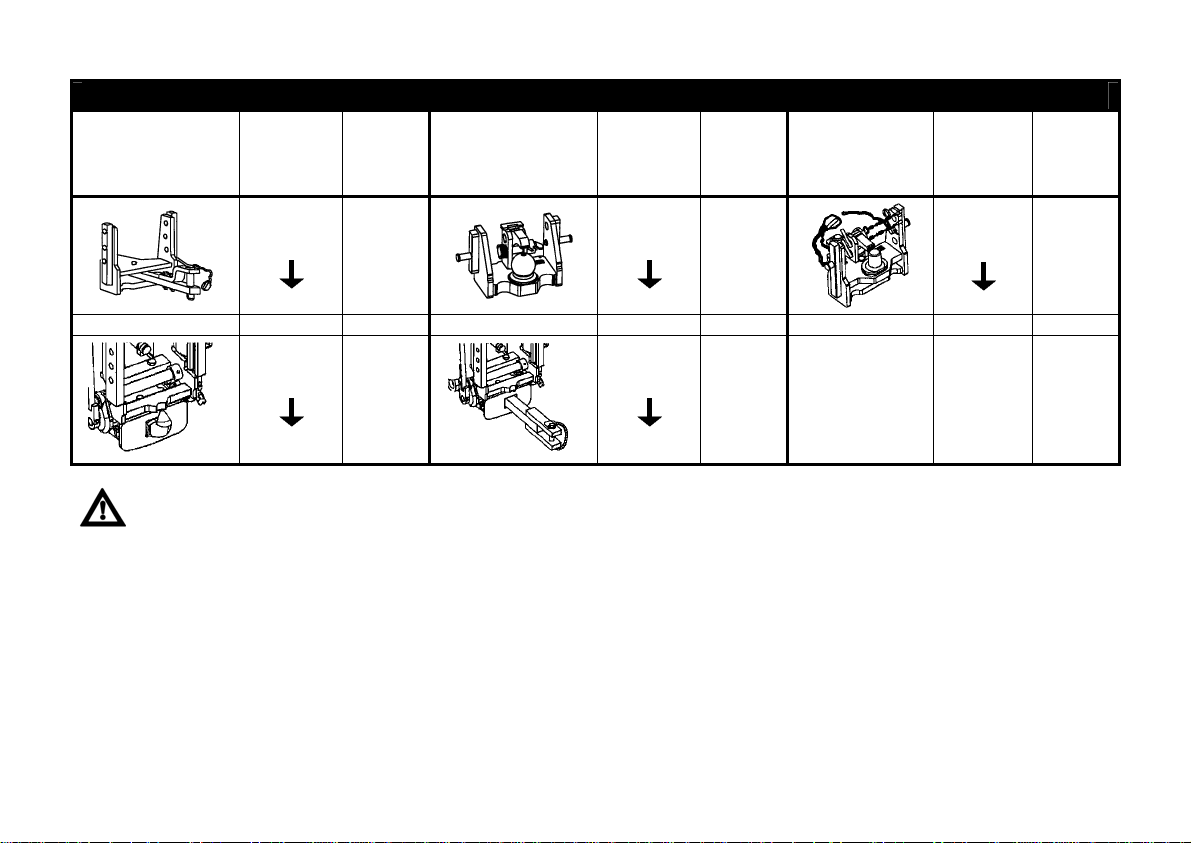
TRANSPORT USE
MAXIMUM PERMITTED VERTICAL STATIC LOADING OF HITCHES FOR TRAILERS AND SEMI-TRAILERS
Permitted
Hitch type
vertical
static
loading
736kg
3,000kg
Diameter
of the pin
(ball) of
the hitch
31mm
47mm
Hitch type
Permitted
vertical
static
loading
3,000kg
1,200kg
Diameter
of the pin
(ball) of
the hitch
80mm
32mm
Hitch type
Permitted
vertical
static
loading
fixed pin
2,000kg
Diameter
of the pin
(ball) of
the hitch
44.5mm
Maximum weight of a coupled braked trailer or semi-trailer shall not exceed the value given on the type plate of the tractor
and value given in the MOT certificate of the vehicle. Maximum speed of the vehicle train is given by the maximum permitted speed of the slower vehicle of the vehicle train.
92

Before connecting a mechanism,
driven by the output shaft of the
tractor, check matching of speeds
of the output shafts of the
mechanism and tractor (540 or
1,000 rpm). Different speeds may
lead to serious damages and
injuries.
DRIVE OF FARMING MACHINES
Work with output shaft...............................................................................................94
Front and rear pto shaft control.................................................................................95
Rear output shaft – shifting of dependent and independent speed of the shaft ........96
Rear output shaft – shifting of speed of the output shaft 540 and 1,000 or 540E rpm96
Front output shaft......................................................................................................96
Facilitating connection of joint shaft of an aggregated machine to the tractor...........97
Replaceable terminals of the rear output shaft.......................................................... 98
Maximum transferred power......................................................................................98
Drive of machines with greater inertial masses.........................................................99
Page
93

DRIVE OF FARMING MACHINES
WORK WITH OUTPUT SHAFT
1. When working with the output shaft pay attention to proper fixing of all
covers.
2. After completion of work install always the output shaft cover.
3. Connect and disconnect the articulated shaft of the coupled mechanism to
the rear output shaft of the tractor always when the engine is stopped,
output shaft disengaged and lever of shifting of dependent and independent rpm of the output shaft in position N - neutral!
4. Connect and disconnect the articulated shaft of the coupled mechanism to
the front output shaft of the tractor always when the engine is stopped and
output shaft disengaged!
5. Perform any repairs or cleaning of parts of the coupled mechanisms
driven by the output shaft only when the engine is stopped, output shaft
disengaged and lever of shifting of dependent and independent rpm of the
output shaft in position N - neutral.
94

DRIVE OF FARMING MACHINES
P+13N010
FRONT AND REAR PTO SHAFT CONTROL
Engagement (with minimum engine revolutions of 1500 min-1) and disengagement of
PTO shafts is done by switches:
(A) standard tractor – placed on the right pillar of the cab.
(B) tractor equipped with electrohydraulics EHR – placed on the external hydraulic
circuit control panel
The switches are equipped with mechanical catches (3) against undesired switch.
When switching the switch, press the catch (3) in the direction of the arrow.
(1) -
The switch controls the rear PTO shaft
(2) -
The switch controls the front PTO shaft
Both PTO shafts are set in motion (front and rear) by switching both switches. The
engagement of PTO shafts is signalized by a lit symbol on the switch.
95

DRIVE OF FARMING MACHINES
G154 G153 E356
REAR OUTPUT SHAFT – SHIFTING
OF DEPENDENT AND INDEPENDENT
SPEED OF THE SHAFT
Shifting is performed by the lever (1)
when the tractor is in standstill.
a -
Independent speed of the output
shaft (rpm of the shaft depends
on rpm of the engine)
n -
Neutral position. Use this position
to facilitate connection of the
farming mechanism propeller
shaft. The terminal of the rear
output shaft is freely rotable.
B -
Dependent speed of the output
shaft (rpm and direction of rotation
depends on the engaged gear and
position of reversing lever).
REAR OUTPUT SHAFT – SHIFTING
OF SPEED OF THE OUTPUT SHAFT
540 AND 1,000 OR 540E RPM
Shifting is performed by the lever (1)
when the tractor is in standstill.
The tractor is equipped standardly with a
combination of 540 and 1,000 rpm of the
output shaft; other optional combination
is 540 and 540E rpm of the output shaft.
a -
1,000 min-1 or 540E min
b -
540 min
-1
Shifting of 540 and 1,000 (or
540E) min
-1
is possible regardless
to the number of splines of the
installed terminal. Speed of the output
shaft and type of terminal shall be chosen depending on the prescribed rpm of
the coupled mechanism.
96
-1
FRONT OUTPUT SHAFT
The front output shaft is equipped with a
fixed terminal with 6 or 21 splines and its
speed in 1,000 min-1.
The tractor may be equipped upon request by a front output shaft with different directions of rotation:
a -
In direction of rotation of the
engine (standard)
b -
Against direction of rotation of the
engine (∗ upon request)

DRIVE OF FARMING MACHINES
FH12N002
FACILITATING CONNECTION OF JOINT SHAFT OF AN AGGREGATED MACHINE TO THE TRACTOR
For facilitating the connection of joint shaft of aggregated machine to a tractor a button (1) placed on mudguards can be used.
With the engine running and rear PTO shaft switch off, spinning of rear PTO shaft
occurs after pressing the button (1). PTO shaft stops spinning after releasing the
button.
Note: Rear PTO shaft revolutions preselection lever must not be in (N) position or in
the position of a dependent revolution of rear PTO shaft.
When manipulating with PTO shaft by means of buttons (1), the operator
must stand beyond the space of the connected tools not to be caught or injured.
97

DRIVE OF FARMING MACHINES
E357
REPLACEABLE TERMINALS OF THE
REAR OUTPUT SHAFT
The tractor is equipped standardly with a
terminal having 6 splines.
∗The tractor may also be equipped upon
request with a replaceable output shaft
terminal having 6 or 21 splines.
Replacement procedure:
1. Using circlip tongs remove the circlip
(1)
2. Pull out the replaceable terminal (2)
in direction of the arrow.
3. Perform installation of a new terminal in reverse order and pay special
attention to installation of the circlip
(1).
Replacement of the terminal shall
be performed when the engine is
stopped.
Rpm of the output shaft and
terminal type shall be chosen
depending on the prescribed rpm
of the coupled mechanism.
Shifting 540 and 1,000 or 540E
-1
min
is possible regardless to the
number of splines of the installed
terminal.
98
MAXIMUM TRANSFERRED POWER
Output shaft Transferred power
front
1,000 min-1 60 kW*
rear
1000 min-1 full engine power
540 min-1 full engine power
540E min-1 full engine power
E358

DRIVE OF MACHINES WITH GREATER INERTIAL MASSES
(CRUSHERS, ROTARY HARROW,
REAPERS, ETC.)
The propeller shaft for drive of such
machines shall be equipped with a socalled free engine clutch that provides
disconnection of the transfer of torques
with backward effects from the machine
to the tractor.
DRIVE OF FARMING MACHINES
99
 Loading...