


PROXIMA HS
/201/201
OPERATOR´S MANUAL
06/2017
100
Tractor is Zetor. Since 1946.
110
12 0

1
ZETOR
This Operator’s Manual for the Zetor tractors, which we are presenting to you will help you to
become familiar with the operation and maintenance of your new tractor.
Although many of you have rich experience with the operation of other tractors, please, read the
information contained in this Operator’s Manual very carefully.
In the Manual you will find a lot of new information and get a perfect overview of how to use the
tractor with maximum efficiency during various kinds of work.
If you observe the rules of tractor operation and maintenance and driving safety, your new tractor will
become your reliable and long-term friend.
The manufacturer of the tractor wishes you thousands of hours of satisfactory work.
ZETOR
The technical specifications and information about the design, equipment, material and app earance are valid at the time
of print. The manufacturer reserves the right to implement changes.
The instructions for use are a part of the machine.
Brno

2

Location of serial numbers ............................................................................................................................ 11
CONTENTS
3
Safety instructions for users ......................................................................................................................... 13
General safety regulations ........................................................................................................................... 13
Proper clothing ............................................................................................................................................ 13
Starting the engine ..................................................................................................................................... 14
Driving operation ......................................................................................................................................... 14
Fire prevention principles ............................................................................................................................ 15
Preventive daily maintenance...................................................................................................................... 16
Driver's seat ................................................................................................................................................. 17
Front passenger´s seat notification ............................................................................................................. 17
Protection of cab against aerosols .............................................................................................................. 17
The level of external noise of tractor ........................................................................................................... 18
The level of internal sound of tractor ........................................................................................................... 18
The level of vibrations on driver´s seat ........................................................................................................ 18
Aggregation tractor - machine/trailer ........................................................................................................... 18
Tractors equipped with front end loader ...................................................................................................... 19
Principles for operating tractors equipped with front end loader ................................................................. 20
Zetor tractors used for work in the woods ................................................................................................... 21
Safety labels ................................................................................................................................................ 21
Preventive daily service ................................................................................................................................. 23
Preventive daily maintenance...................................................................................................................... 23
Fuel system leaks ........................................................................................................................................ 23
Engine oil level ............................................................................................................................................ 23
Cooling system ............................................................................................................................................ 23
Liquid brakes ............................................................................................................................................... 24
Trailer brakes ............................................................................................................................................... 24
Hydrostatic steering ..................................................................................................................................... 24
Air cleaner ................................................................................................................................................... 24
Cab filtration................................................................................................................................................. 25
Hitches ......................................................................................................................................................... 25
Inspection of fouling of coolers .................................................................................................................... 25
After work with front implements and in case of cooler clogging ............................................................... 25
Tyres and wheels ........................................................................................................................................ 26
Short functional test .................................................................................................................................... 26
Acquaintance with tractor.............................................................................................................................. 27
Safety cab .................................................................................................................................................... 27
Opening doors from the outside .................................................................................................................. 27
Opening the door from the inside ................................................................................................................ 27
Rear window ................................................................................................................................................ 28
Side window................................................................................................................................................. 28
Emergency exits .......................................................................................................................................... 28
Sun screen................................................................................................................................................... 28
Shelf ............................................................................................................................................................. 29
Tools box ..................................................................................................................................................... 29
Right rear panel ........................................................................................................................................... 29
Internal lighting ............................................................................................................................................ 29
Rear view mirrors ........................................................................................................................................ 30
Aggregation opening ................................................................................................................................... 30
Passenger´s seat ......................................................................................................................................... 30
Driver's seat Mars Svratka .......................................................................................................................... 31
Driver's seat Sears ...................................................................................................................................... 32
Driver´s seat ................................................................................................................................................ 32
Tilt steering wheel ........................................................................................................................................ 33
Tilting and protrusion of steering wheel ....................................................................................................... 33
Heating control panel, * air-condition .......................................................................................................... 34
Heating valve control (A) ............................................................................................................................. 34
Switch air-condition (C) ............................................................................................................................... 34
Air circulation in cabin control (D) ................................................................................................................ 35
Proper function of the heating and air-condition system ............................................................................. 35
Fast heating of the cabin area ..................................................................................................................... 35
Fast cooling of the space of the cabin ......................................................................................................... 35
Operation of heating or air-condition with tractor´s work ............................................................................. 36
Immediately after cooling the cabin ............................................................................................................. 36

Air-condition and heating registers (A) ........................................................................................................ 36
CONTENTS
4
Front windshield (B) defrosting .................................................................................................................... 37
*Air filter with active carbon ......................................................................................................................... 37
Control panel on right cab pillar ................................................................................................................... 38
Wiper and washer of the front window ........................................................................................................ 38
Front wiper speed switch ............................................................................................................................. 38
Rear window wiper ...................................................................................................................................... 39
Washer nozzle ............................................................................................................................................. 39
Windshield washer tank .............................................................................................................................. 39
Panel of the instrument panel ...................................................................................................................... 40
Lights switch ................................................................................................................................................ 41
Switch of warning lights ............................................................................................................................... 41
Lights switch between the grill and the cabin .............................................................................................. 41
Direction lights, lower beam head lights, head lights and horn switches .................................................... 41
Front wheel drive switch .............................................................................................................................. 42
Push button of rear, front differential locks .................................................................................................. 42
Switch box ................................................................................................................................................... 42
Switch box key in the position (0) ................................................................................................................ 43
Switch box key in the position (I) ................................................................................................................. 43
Switch box key in the position (II) ................................................................................................................ 43
Manual throttle ............................................................................................................................................. 43
Pedals and levers ........................................................................................................................................ 44
Reversing lever ............................................................................................................................................ 44
Gear shifting lever ....................................................................................................................................... 44
Gear shifting scheme ................................................................................................................................... 44
Road and reduced speeds shifting lever ..................................................................................................... 45
PTO selection control lever ......................................................................................................................... 45
Lever of shifting of speed 540 (or 540E) and 1,000 rpm of the rear output shaft ....................................... 45
Lever of hand brake and hitch for single-axle trailer ................................................................................... 45
Battery disconnector .................................................................................................................................... 46
Fuel tank ...................................................................................................................................................... 46
Fuel tank drain plug ..................................................................................................................................... 46
Urea tank ..................................................................................................................................................... 47
Instrument panel ............................................................................................................................................. 49
Instrument panel - signal lamps................................................................................................................... 49
Instrument panel - instruments .................................................................................................................... 50
Instrument panel - buttons ........................................................................................................................... 50
Display description ...................................................................................................................................... 51
Change of the look of display ...................................................................................................................... 51
Change in the display contrast .................................................................................................................... 51
Display - change of display .......................................................................................................................... 51
The average speed and the fuel consumption of the tractor ....................................................................... 55
Display - resetting data ................................................................................................................................ 55
Display - manual brake ................................................................................................................................ 56
Display - indicator of service inspection intervals ........................................................................................ 56
Exceeding the service interval ..................................................................................................................... 56
Zeroing (reset) of the indicator of service inspection intervals .................................................................... 57
Error signalling ............................................................................................................................................. 57
Display - error messages ............................................................................................................................. 58
Description of the display of error messages .............................................................................................. 58
Symbols of tractor nodes ............................................................................................................................. 59
Display - service menu ................................................................................................................................ 59
Service menu ............................................................................................................................................... 59
Display - history of defects .......................................................................................................................... 60
Display - setting language mutation ............................................................................................................ 60
Display - setting and calibration................................................................................................................... 60
Travel speed calibration ............................................................................................................................. 61
Setting of the display of the rear PTO shaft speed...................................................................................... 62
Setting of time .............................................................................................................................................. 63
System of treatment of exhaust gases - setting .......................................................................................... 64
Instrument panel - warning .......................................................................................................................... 65
Replenish fuel .............................................................................................................................................. 65
Add urea ...................................................................................................................................................... 65

High temperature of the cooling liquid ......................................................................................................... 66
CONTENTS
5
High oil temperature in the gearbox ............................................................................................................ 66
Full pushing filter of the gearbox distributor ................................................................................................ 67
Full pushing filter of the hydraulics .............................................................................................................. 67
System of additional treatment of exhaust gases ....................................................................................... 69
Conditions for DPF operation ...................................................................................................................... 70
Error signalling of DPF system .................................................................................................................... 71
Conditions for SCR system operation ......................................................................................................... 71
Urea (Aqueous Urea Solution AUS 32, DEF) .............................................................................................. 72
Principles for safe handling of urea (AUS 32, DEF) .................................................................................... 72
Error signalling of SCR system.................................................................................................................... 73
Indication of amount of urea in the tank ...................................................................................................... 73
Indication of DPF and SCR errors on the display of the instrument panel .................................................. 74
Reduction of the engine power and engine revolutions .............................................................................. 75
Signalling of whether DPF is full .................................................................................................................. 76
Long-term shutdown of tractor ..................................................................................................................... 76
Repairs and maintenance of the system of additional treatment of exhaust gases .................................... 76
System of treatment of exhaust gases - setting .......................................................................................... 77
Automatic regeneration of the diesel particulate filter - EAT REGENERATION AUTO .............................. 77
Inhibition of regeneration of the diesel particulate filter - EAT REGENERATION INHIBIT ......................... 78
Operation ......................................................................................................................................................... 79
Before you start the engine ......................................................................................................................... 79
Non-permitted starting ................................................................................................................................. 79
*Coolant heater ............................................................................................................................................ 79
Starting the engine while using coolant heater ............................................................................................ 80
Starting the engine ...................................................................................................................................... 80
If engine does not start ................................................................................................................................ 81
Ignition system failure signalization ............................................................................................................. 81
Immediately after start ................................................................................................................................. 81
Engine heating ............................................................................................................................................. 82
Error signalling ............................................................................................................................................. 82
Indication of the limitation of the engine power and engine revolutions ...................................................... 82
Diesel particle filter ...................................................................................................................................... 83
Filter of solid particles - indication of operation and failures of the system ................................................. 83
Diesel particle filter regeneration ................................................................................................................. 84
Gear shifting ................................................................................................................................................ 85
Reversing lever ............................................................................................................................................ 85
Reversing lever position signalization ......................................................................................................... 85
Driver´s seat - safety switch ........................................................................................................................ 86
Shifting road and reduced speeds ............................................................................................................... 86
Gear shifting from lower to higher gears ..................................................................................................... 86
Gear shifting from higher to lower gears ..................................................................................................... 86
The principles of appropriate use of tractors ............................................................................................... 87
The description of the system of travel clutches ......................................................................................... 87
The way of controlling the travel clutch by .................................................................................................. 87
The differences in ways of controlling the travel clutch by .......................................................................... 87
Interrupted sound signal .............................................................................................................................. 88
Dead start of the tractor ............................................................................................................................... 88
Dead start of tractor in regular operation - automatic dead start function ................................................... 88
Dead start of tractor in regular operation - clutch pedal .............................................................................. 88
Dead start - using the clutch pedal .............................................................................................................. 89
Change the direction of drive ....................................................................................................................... 89
Change the direction of drive by means of reversing lever ......................................................................... 89
Change the direction of drive - using the clutch pedal ................................................................................ 90
Gear shifting ................................................................................................................................................ 90
Gear shifting - Using the clutch pedal ......................................................................................................... 90
Gear shifting - using the clutch control button on the head of gear shifting lever ...................................... 90
Blocking the automatic dead start function .................................................................................................. 90
Three-gear torque multiplier ........................................................................................................................ 90
Indication of the multiplier function .............................................................................................................. 91
Increasing, decreasing the travel speed by two gears ................................................................................ 91
Multiplier preselection switch ....................................................................................................................... 91
Automatic multiplier shifting ......................................................................................................................... 92

Travelling up the slope ................................................................................................................................ 93
CONTENTS
6
Travelling down the slope ............................................................................................................................ 93
Differential lock ............................................................................................................................................ 93
Control of front driving axle .......................................................................................................................... 94
Driving with engaged front driving axle ....................................................................................................... 94
Foot brakes .................................................................................................................................................. 94
Air brakes of trailers and semi-trailers ......................................................................................................... 95
Warning indication of air pressure drop ....................................................................................................... 95
One-hose and two-hose brakes .................................................................................................................. 95
One-hose brakes ......................................................................................................................................... 95
Two-hose brakes ......................................................................................................................................... 96
Hydraulic brakes of trailers .......................................................................................................................... 96
Connecting and disconnecting quick couplings of trailer hydraulic brakes ................................................. 96
Stopping the engine ..................................................................................................................................... 97
Leaving the tractor ....................................................................................................................................... 97
Warning signalization of hydrostatic steering failure ................................................................................... 97
Important warnings ...................................................................................................................................... 98
Running-in the tractor .................................................................................................................................... 99
General principles of new tractor run-in in first 100 hours of operation....................................................... 99
In first 10 hours of operation ........................................................................................................................ 99
From 100 hours of operation ....................................................................................................................... 99
Transport use ................................................................................................................................................ 101
Front hook .................................................................................................................................................. 101
Multistage adjustable suspension ............................................................................................................. 101
Height adjustment and disassembly of the CBM stage hitch .................................................................... 101
Automatic mouth of the CBM stage hitch .................................................................................................. 102
Modular system of hitches for trailers and semi-trailers ............................................................................ 102
Swinging draw-bar console module .......................................................................................................... 102
Swinging draw-bar console with a fixed pin module ................................................................................. 102
Console with a ø 80 ball module ............................................................................................................... 103
Towing bar ................................................................................................................................................. 103
Hitch for a single-axle CBM semi-trailer .................................................................................................... 103
Coupling of a single-axle trailer ................................................................................................................. 103
Uncoupling of a single-axle trailer ............................................................................................................. 104
Hook of the mounting for a single-axle trailer ............................................................................................ 104
Coupling with a trailer or semi-trailer ......................................................................................................... 104
Maximum permissible vertical static load of hitches for trailers and semi-trailers ..................................... 105
P.T.O. drive of agricultural machines ......................................................................................................... 107
Work with PTO shaft .................................................................................................................................. 107
Front and rear PTO shaft control ............................................................................................................... 107
Display of revolutions of the PTO shaft ..................................................................................................... 108
Replaceable end points of rear PTO shaft ................................................................................................ 109
Facilitating connection of joint shaft of an aggregated machine to the tractor .......................................... 109
Switching on the rear PTO shaft - independent revolutions ...................................................................... 110
Switching on the rear PTO shaft - dependent revolutions ......................................................................... 110
Front PTO shaft ......................................................................................................................................... 111
Maximum transferred output ...................................................................................................................... 111
Drive of machines with greater inertia masses .......................................................................................... 111
Hydraulic system .......................................................................................................................................... 113
Hydraulic system ....................................................................................................................................... 113
Hydraulics control panel ............................................................................................................................ 113
Amount of oil taken from outer hydraulic drives ........................................................................................ 114
Connecting and disconnecting quick-couplers .......................................................................................... 114
Quick-couplings with drip collection .......................................................................................................... 114
Connecting machines and tools to External hydraulic circuit .................................................................... 115
Front outlets of the external hydraulic circuit ............................................................................................. 115
Control of the external hydraulic circuit front outlets ................................................................................. 116
Mechanical hydraulics ................................................................................................................................. 117
Ways to regulate inner hydraulic circuit ..................................................................................................... 117
Controlling the inner hydraulic circuit ........................................................................................................ 117
Free (floating) position ............................................................................................................................... 118
Adjustable stop .......................................................................................................................................... 118
Three-point hitch lowering speed control .................................................................................................. 118

Hydraulic system sensitivity control ........................................................................................................... 118
CONTENTS
7
Position regulation of the lifting of the rear three-point hitch ..................................................................... 119
Power regulation of the lifting of the rear three-point hitch ........................................................................ 120
Mixed regulation of lifting the rear three-point hitch .................................................................................. 120
Exterior rear hydraulic arms controls ......................................................................................................... 121
Outer hydraulic circuit ................................................................................................................................ 121
Outer hydraulic circuit controls .................................................................................................................. 122
Locking control levers ................................................................................................................................ 122
Different functions of outer hydraulic circuit control levers ........................................................................ 123
Electro-hydraulic system ............................................................................................................................. 125
Control element functions .......................................................................................................................... 125
Equipment 'OFF' ........................................................................................................................................ 125
Blocking cancellation ................................................................................................................................. 126
Quick sinking ............................................................................................................................................. 126
Transport of implements ............................................................................................................................ 127
Stop position .............................................................................................................................................. 127
Vibration compensator (damper) ............................................................................................................... 127
Limitation of the upper position of the three-point hitch ............................................................................ 128
Lowering speed ......................................................................................................................................... 128
Free position .............................................................................................................................................. 128
Setting the control of three-point hitch ....................................................................................................... 128
Manual setting of control of three-point hitch ............................................................................................ 129
Automatic control of three-point hitch ........................................................................................................ 129
Using the rear control ................................................................................................................................ 130
External control buttons of the electro-hydraulic system ........................................................................... 130
Indication of EHR-B errors ......................................................................................................................... 131
Description of minor errors of the EHR-B electro-hydraulic system .......................................................... 132
Outer hydraulic circuit ................................................................................................................................ 133
Outer hydraulic circuit controls .................................................................................................................. 133
Locking control levers ................................................................................................................................ 133
Different functions of outer hydraulic circuit control levers ........................................................................ 134
Hitches ........................................................................................................................................................... 137
Rear three-point hitch ................................................................................................................................ 137
Safety principles of working with the three-point hitch .............................................................................. 137
Height adjustment of the lifting draw-bars ................................................................................................. 138
Fixed and free position of the lower hydraulic draw-bars .......................................................................... 138
Limiting draw-bars ..................................................................................................................................... 138
Upper pull rod ............................................................................................................................................ 139
Selection of holes in the bracket................................................................................................................ 139
*Lower draw bar with slipping out end pieces ........................................................................................... 140
*Lower draw bar with CBM hooks ............................................................................................................. 140
Securing lower draw bars with CBM hooks ............................................................................................... 140
*Front three-point hitch .............................................................................................................................. 140
Controlling front three-point hitch .............................................................................................................. 141
Adjusting the lowering rate of the front three-point hitch ........................................................................... 141
Hydraulic lock of the front three-point hitch ............................................................................................... 141
Working and transport position of the front three-point hitch .................................................................... 142
Driving with agricultural machines attached to the front three-point hitch ................................................. 142
Wheel tread change ...................................................................................................................................... 143
Change of front wheels track with front drive axle..................................................................................... 143
Gauges of the front wheels of the front drive axle of the tractors equipped with screwed footer discs .... 143
Possible adjustable tracks of the front wheels of the front driving axle of the tractors.............................. 143
Front wheels track of front drive axle in tractors equipped with non-removable discs .............................. 144
Front wheels toe-in .................................................................................................................................... 144
Adjustment of toe-in of the wheels of the front driving axle ....................................................................... 145
Setting wheel stops with front drive axle ................................................................................................... 145
Front drive axle fenders ............................................................................................................................. 146
Rear wheels wheel track ........................................................................................................................... 146
Gauges of the tractor rear wheels equipped with screwed footer discs .................................................... 146
Rear wheel track change ........................................................................................................................... 147
The gauges of the tractor rear wheels equipped with solid discs .............................................................. 147
Additional weights ........................................................................................................................................ 149
Weights in front of the bonnet mask .......................................................................................................... 149

Weights of the front three-point hitch ........................................................................................................ 149
CONTENTS
8
Weights of rear wheels .............................................................................................................................. 149
Valve for filling tyre tubes with liquid ......................................................................................................... 149
Chocking of front wheels ........................................................................................................................... 150
Procedure of filling the tyres with liquid ..................................................................................................... 150
Procedure of draining liquid from the tyres ................................................................................................ 151
Antifreeze solution for tyre filling................................................................................................................ 151
Electric installation ....................................................................................................................................... 153
Basic service information ........................................................................................................................... 153
Accumulator battery ................................................................................................................................... 153
Battery disconnector .................................................................................................................................. 154
Accumulator battery maintenance ............................................................................................................. 154
Alternator ................................................................................................................................................... 155
Alternator maintenance ............................................................................................................................. 155
Electric installation overload ..................................................................................................................... 155
Fuse panel ................................................................................................................................................. 156
Checking the adjustment of the front grill headlights ................................................................................ 158
Adjusting the front grill headlights ............................................................................................................. 158
Checking the adjustment of the cab roof headlights ................................................................................. 159
List of lamps............................................................................................................................................... 159
Tractor maintenance .................................................................................................................................... 161
Service inspections .................................................................................................................................... 161
Steps performed daily before the start of work .......................................................................................... 161
Steps performed every 50 hours of work .................................................................................................. 161
Steps performed every 100 hours of work ................................................................................................ 161
Steps performed every 500 hours of work ................................................................................................ 161
Steps performed outside the interval of 500 hours of work ....................................................................... 162
Monthly performed actions ........................................................................................................................ 162
Filling and filter replacement ...................................................................................................................... 163
Fuels, coolants and lubricants used - amounts ......................................................................................... 164
ZETOR service fillings ............................................................................................................................... 164
Motor oils ................................................................................................................................................... 164
Oil in the gearbox and final drivehousing .................................................................................................. 164
Oil in the rear axle gantries ........................................................................................................................ 164
Oil for the front driving axle ........................................................................................................................ 164
Oil for the hydrostatic steering of the tractors ............................................................................................ 164
Specification of oils for Zetor engines equipped by diesel particle filter .................................................... 164
Specification of the oil for the gearbox housing and the final drive housing ............................................. 164
Specification of the oil for the portals ........................................................................................................ 165
Specification of oil for the front driving axle ............................................................................................... 165
Specification of oil for the tractor hydrostatic control system .................................................................... 165
Other recommended service fillings tested on Zetor tractors .................................................................... 165
Oils for Zetor engines which are equipped with diesel particle filter ......................................................... 165
Oil in the gearbox and final drivehousing .................................................................................................. 165
Oil in the rear axle gantries ........................................................................................................................ 166
Oil for the front driving axle ........................................................................................................................ 166
Oil for the hydrostatic steering of the tractors ............................................................................................ 167
Front PTO oil ............................................................................................................................................. 167
Plastic lubricant for the tractor ................................................................................................................... 167
Hydraulic brake liquid for the tractors ........................................................................................................ 168
Liquid for the cooling system of the tractors .............................................................................................. 168
Fuel for Zetor engines which are equipped with diesel paricle filter .......................................................... 168
Urea (urea solution AUS 32) ..................................................................................................................... 168
Tractor greasing plan ................................................................................................................................. 169
Safety instructions for lubrication of the tractor ......................................................................................... 169
Solid front drive axle .................................................................................................................................. 169
Hitch for a single-axle semi-trailer ............................................................................................................. 169
Front three-point hitch ............................................................................................................................... 169
Three-point hitch ........................................................................................................................................ 170
Hitch mouth for a trailer ............................................................................................................................. 170
Upper linkage bracket ................................................................................................................................ 170
Technical maintenance of the tractors after a general overhaul of the main groups ............................... 170
Maintenance instructions ............................................................................................................................ 171

Front bonnet opening ................................................................................................................................ 171
CONTENTS
9
Checking oil levels in engine ..................................................................................................................... 171
Draining oil from engine ............................................................................................................................. 171
Replacing full-continuous motor oil filter .................................................................................................... 172
Pouring oil to engine .................................................................................................................................. 172
Fuel filter element replacement ................................................................................................................. 172
Fuel system venting ................................................................................................................................... 173
Replacement of carter exhaust oil separator filter element ....................................................................... 173
Maintenance instruction of dry air filter ...................................................................................................... 173
Main air filter element regeneration ........................................................................................................... 174
Replacing dry filter locking element ........................................................................................................... 174
Back assembly of air filter elements .......................................................................................................... 174
Checking amount of oil in hydrostatic steering tank .................................................................................. 174
Replacing oil and hydrostatic steering filter element ................................................................................. 175
Venting hydraulic circuit of hydrostatic steering ........................................................................................ 176
Replacing the hoses of hydrostatic steering .............................................................................................. 176
Replacing coolant ..................................................................................................................................... 177
Check and replacement of oil in gearbox, axle drive and rear axle portals .............................................. 177
Drainage and inspection holes .................................................................................................................. 178
Changing suction filter ............................................................................................................................... 178
Replacement of the transmission oil cleaner element with hydraulic pump suction filter ........................ 179
Gearbox distributor - replacement of oil cleaner cartridge ........................................................................ 179
Front PTO ................................................................................................................................................. 179
Filling, controlling and draining hole of oil of front drive axle ..................................................................... 180
Filling, controlling and draining hole of oil of front wheels reducers .......................................................... 180
Brake fluid replacement ............................................................................................................................. 180
Cleaning the heating filters ........................................................................................................................ 181
Air filter with active carbon ........................................................................................................................ 181
Carbon filter installation instructions .......................................................................................................... 181
Air-conditioning maintenance ................................................................................................................... 182
Draining condensate from the air reservoir .............................................................................................. 182
Checking the air systems for leaks ........................................................................................................... 182
Working pressure of air brakes ................................................................................................................. 183
Maintenance and treatment of tyres ......................................................................................................... 183
Storing the tractor ...................................................................................................................................... 183
Diesel particle filter maintenance .............................................................................................................. 183
Adjustment .................................................................................................................................................... 185
Cogged belt tension ................................................................................................................................... 185
Bleeding of tractor brake system ............................................................................................................... 185
1. Bleeding of pressure air brake system for trailers ................................................................................. 186
2. Bleeding of rear wheel brakes ............................................................................................................... 186
3. Bleeding of the brake system of front driving axle ................................................................................ 187
4. Bleeding the hydraulic brakes of a trailer .............................................................................................. 187
Check and adjustment of service and parking brakes .............................................................................. 188
Service brake adjustment .......................................................................................................................... 189
Parking brake adjustment .......................................................................................................................... 189
Adjustment of free travel of brake pedals .................................................................................................. 190
Adjustment of hitch for single-axle trailers ................................................................................................. 190
Adjustment of bowden cable ..................................................................................................................... 190
Main technical parameters........................................................................................................................... 191
Main tractor's parameters (mm) ................................................................................................................ 191
Technical data of engines .......................................................................................................................... 192
Permitted maximum load of front axle (kg) ................................................................................................ 193
Permitted maximum load of rear axle (kg) ................................................................................................ 193
Permitted maximum weight of set 'tractor + mounted machine' (kg) ........................................................ 193
Manoeuvrability condition .......................................................................................................................... 193
Front tires steerability ................................................................................................................................ 194
Change of the load-bearing capacity of the front tyres (%) ....................................................................... 194
Bearing capacity of rear tires ..................................................................................................................... 195
Change of the load capacity of the rear tyres (%) ..................................................................................... 197
Permitted combinations of wheels for tractors .......................................................................................... 197
Performance on rear PTO shaft ................................................................................................................ 197
Lifting force of the three-point hitch ........................................................................................................... 197

Tensile force .............................................................................................................................................. 198
CONTENTS
10
Forward travelling speed of the tractor - 40 km/h ...................................................................................... 198
Backward travelling speed of the tractor - 40 km/h ................................................................................... 199
Rear independent PTO shaft rotation ........................................................................................................ 199
Speed of the Zuidberg front PTO .............................................................................................................. 200
Clearance-circle and turning circle diameter ............................................................................................. 200
Calculation of tractor load limit .................................................................................................................. 201
Index............................................................................................................................................................... 205

1. Tractor data plate
g
LOCATION OF SERIAL NUMBERS
11
2. Cab serial number
3. Engine serial number
4. Tractor serial number
When ordering spare parts and within all written and oral communication always specify the data of your
tractor that should be written in the frames below.
Tractor type
Tractor serial number
En
ine serial number

LOCATION OF SERIAL NUMBERS
12
The 'right', 'left', 'front' and 'back' indications refer to the
driving direction of the tractor.
G3

Please, pay increased attention to the parts of the Operator´s Manual that a re marked with this
SAFETY INSTRUCTIONS FOR USERS
13
symbol.
This symbol accompanies all important warnings that concern operation safety. Observe these
instructions and be extremely careful in these cases! Inform your colleagues and other users about these
warnings.
Carefully study the chapters marked with this symbol before starting to perform operation, repairs and
adjustments of your tractor.
This symbol identifies all important information concerning operation, adjustment and repairs of the
starter motor. Observe these instructions and be extremely careful in these cases!
This symbol marks parts of the Operator´s Manual concerning environment protection. Or possibly
sections describing handling of dangerous waste.
∗ This symbol refers to optional tractor accessories installed by the manufacturer on the customer´s
request.
Instruction manual´s passages related only to models equipped with DPF (diesel particle filter) are
labelled with this symbol.
Accessories that are not installed by the manufacturer in the standard way or * optionally on
the customer´s request (in the production plant) cannot be subject to a claim.
General safety regulations
z The tractor may only be operated by a trained person that has a valid driving licence and has been
thoroughly acquainted with the operation and safety rules.
z Besides the safety instructions mentioned in the Operator´s Manu al you are obliged to respect
generally valid safety and traffic rules of the country where the tractor is used.
Proper clothing
z Do not wear loose clothing and free flying long hair.
z During all work use suitable (prescribed) means of personal protection (working boots, gloves,
goggles, etc.)

g
SAFETY INSTRUCTIONS FOR USERS
14
Starting the engine
z The engine cannot be started by driving the tractor downhill.
z The engine cannot be started by towing the tractor with another tractor.
z Only start the engine from the driver's seat with the shift lever and reversing lever in the neutral
position, PTO switched off and the clutch pedal depressed.
Life hazard when starting by means of short-circuiting the starter terminals!
z The key in the switch box must be in the 'I' position.
z When heating the engine with the * electric hea ter first plug the power supply cord to the heater and
only then to the electric mains. After the end of heating first disconnect the heater from the electric
mains.
z Caution! Electric shock hazard!
Driving operation
z Hoses of the hydrostatic steering, brakes and fuel system must be checked and replaced if any signs
of damage are found. These are some exa mples of hose damage signs: - cracks on the hose surface,
releasing of pre-tensioning of hose connection (which can be verified by easy removal of the hose
from the connection) and mechanical damage of the hose. Hoses with indicated service life must be
replaced immediately after the expiration of the service period.
z During driving on roads with trailers and tools the brake pedals must be conne cted with a latch.
z The brakes and steering must be in the perfect condition all the time.
z Driving downhill without an engaged gear is forbidden.
z Switching the reversing lever at a sp eed over 10 km/h is forbidden.
z Pay special attention when driving on a slope and muddy, sandy, icy or uneven ground.
z Observe the maximum specified inclination ang le, i.e. 12°.
z Respect the total permissible weight of the tractor and trailer specified on the data plate of the tractor
or on the rear wheel mud-guard.
z Do not use the differential lock when driving into a bend.
z It is forbidden to get into and out of a moving tractor.
z When driving the tractor with agricultural machines attached to the front three-point hitch, reduce the
driving speed to 15 km/h.
z When driving with machines attached to the rear hitches the load of the steered axle must not drop
below 20% of the current weight of the set. With the driving speed reduced to 20 km/h the load of the
steered axle may drop to 19% of the current weight of the set (set below 4.5 t) or to 18% of the current
weight of the set (set exceeding (4.5 t).
z During aggregations of the tractor with machines pay attention to possible worsening of stability of the
aggregated unit which may be influenced by the connected machine.
z During aggregation of Zetor tractors with machines and implements with high tensile resistance when
the engine speed drops and the engine tends to stall, the 1R, 2R reduced gears must not b e used for
the work with these machines (risk of shaft twist-off).
z The number of persons transported by the tractor must not exceed the number specified in the
technical certificate of the tractor.
z Persons that are not authorized to work with the attached implement must not stand between the
tractor and the hitched machine (implement).
z Before puttin
the tractor in motion make sure there is no person or obstacle in the driving direction.

SAFETY INSTRUCTIONS FOR USERS
15
Recovery, pushing
z To recover a tractor that has sunk in mud use a tow bar or rope attached to the front hook
Never use chains! Rupture of the chain represents a danger of death!
z During recovery it is dangerous to stand near the towing rope.
z It is prohibited to use the tractor axles (individual wheels) as a winch for releasing a sunken tractor.
z The front hook should be only use to recover the entire tractor, i.e. without any trailer or another
attached implement.
z Never recover the tractor with reduced gears engaged.
z When pushing other vehicles (trailers, implements, etc.) with the tractor never insert free wooden
blocks or bars between the tractor and the pushed vehicle.
z In case of use of the tractor for wrecking or towing purposes, use only the rear hitch.
z When towing the tractor, the reduction gear shift lever must be in the neu tral position.
Leaving the tractor
z Park the tractor only on an even land and where not possible, support with a shim assy.
z Do not park the tr actor with an attached implement in the lifted position.
z Usually use the left-hand side tractor door when leaving the tractor. Look round whether any vehicle is
coming, that could jeopardize your safety when leaving the tractor.
z Use steps and handles when leaving the tractor. When leaving the tractor by the right-hand side door
pay attention being in space of shifting lever and hand throttle control.
z Brake the tractor with parking brake before leaving tractor with running engine.
z Before leaving the tractor, do not forget to secure the tractor by manual brake. Engaging a gear does
not secure the tractor against rozjetím (clutch is disengaged), remove the key from the switchbox and
lock the cabin.
With stopped engine only
z All work connected with refuelling, cleaning, lubricating and adjusting the tractor or attached
implements may only be performed with the engine and moving parts of the tractor stopped except
functional checks of the brakes, hydraulic system and charging.
z Before removing the side plates of the hood it is always ne cessary to stop the engine. The tractor
engine can only run in a closed building or room if sufficient ventilation is ensured. Exhaust gases are
harmful for health.
Fire prevention principles
z Refuel the tractor best after the end of work and with the engine stopped.
z Do not refill fuel up to the top of the fuel tank in summer. Wipe spilt fuel immediately.
z Do not refuel the tractor near open flame and do not smoke.
z Do not smoke and do not use open flame when inspecting the battery electrolyte level.
z Make sure that fire safety instructions are strictly observed in environments with an increased danger
of fire (hay-lofts, straw-stacks, etc.).
z The tractors are not equipped with a fire extinguisher from the production plant.

SAFETY INSTRUCTIONS FOR USERS
16
Health and environment protection
z The tractors are not equipped with special filters of air aspirated to the cab. Therefore, they are not
designed for work with aerosols and other harmful substances.
z Coolant, brake liquid, kerosene, diesel fuel, mineral oil and other oil products that are used for the
operation and maintenance of the tractor may cause various skin disorders in case of direct contact
with your skin and can irritate mucous membranes, eyes, the digestive system and upper respiratory
ways. Some of them may even cause systemic poisoning when swallowed.
z Persons that handle oil products are obliged to strictly observe safety and hygienic regulations, use
suitable means of protection and work in well ventilated rooms.
Working with oil products
z After the end of work or before a m eal you should wash yourself with a mild agent and treat your
hands with a suitable ointment or cream.
z When connecting and disconnection quick-couplers of the hydrau lic circuits use any piece of clo th to
remove residual oil remaining in the socket or on the plug of the quick-coupler.
Waste disposal
z When disposing of the tractor or its parts (incl. operation liquids) after the end of their service life you
must observe relevant provisions of valid acts and implementation directives of these acts of the
country where the tractor is used. The last seller of the tractor is obliged in accordance with the Waste
Act to inform the consumer - during the sale of the tractor - about the way of collection of some used
parts of the tractor. This is the case of oil and other operation liquids, batteries and tyres. These used
products must be received from the consumer without any obligation of the consumer to pay for this
service.
Preventive daily maintenance
z Perform this maintenance daily or after every 8 - 10 hours of operation at the latest.
Safety cab
z If the protective frame of the safety cab is damaged by corrosion, an accident or otherwise, the safety
cab must be replaced.
Air-conditioning
z Disassembling, turning or otherwise handling the screw union of the air-conditioning system is not
allowed in any case. Sudden leak of the coolant may occur, causing quick local cooling. Contact or
freezing of components in hands may cause serious damage of so me tissues.
z The air-conditioning system is equipped with quick-couplers that make it possib le to separate the cab
from the tractor body if necessary without any coolant leak. Entr ust interventions into the airconditioning system to a specialized repair shop.

SAFETY INSTRUCTIONS FOR USERS
17
Electric installation
No additional interventions into the electric installation (connection of other electric
appliances) are permissible due to its possible overloading!
z The values of the electric installation are:
Nominal voltage 12 V =
Grounded minus pole ( - ) pole
z Using starting trucks or auxiliary power supplies with a different voltage or polarity may cause serious
failures of the tractor.
z When handling the battery you must pay increased attention and a vo i d short-circuits. In tractors
equipped with a battery disconnector switch the disconnector off when handling the battery.
z Zetor tractors must not be operated with a disconnected battery as this may lead to a serious failure of
the tractor.
Work in a chemically aggressive environment
z If the tractor is operating in a chemically aggressive environment (e.g. working with chemical sprays,
fertilizers, in environments with high concentrations of salt, etc.), it is always necessary to clean the
tractor thoroughly from chemically aggressive substances and neutralize them after the termination of
the work according to the manufacturer's instructions.
Driver's seat
If the driver's seat is equipped with a safety belt, this retaining system must be used during
operation of the tractor.
Front passenger´s seat notification
ATTENTION:
Transportation of personnel on front passenger´s seat is
allowed only with road transportation.
- Transportation of front passenger outside the
seat designed for this purpose is forbidden.
- Using the seat for front passenger during the work
with a tractor (e.g. during the work on the fields) is
explicitly forbidden.
- The use of safety belt on front passenger´s seat is
governed by valid regulations. In this respect, keep
the regulations valid in the country, where the tractor
is operated.
FH13N002
Protection of cab against aerosols
The cab of Zetor tractors in standard design is not
designed for work with aerosols and other health
hazardous substances.
The level of cab protection in standard design complies
with EN 15695-1:2009 standard - level 2 (only dust proof
cab).
FH13N003

r
plug
SAFETY INSTRUCTIONS FOR USERS
18
The level of external noise of tracto
The exposition to the effects of high levels of noise for a longer period of time may lead to
hearing disorders or deafness. Protect your hearing with protective means, e.g. headphones, ear
s etc.
Resulting levels of noise when measuring noise for hearing of a person near a tractor. Based on European
directive 2009/63/EC - Amendment VI.
Model Proxima HS 100 Proxima HS 110 Proxima HS 120
Travel speed 40 km 40 km 40 km
Tractor noise levels when travelling dB 83 83 80
Tractor noise levels when standing dB 83 83,5 80
The level of internal sound of tractor
The exposition to the higher sound levels for longer periods of time may lead to hearing
disorders or deafness. Protect your hearing with protective measures, e.g. headphones, ear plugs
etc.
Resulting levels of noise when measuring noise for hearing of driver. Based on European directive
2009/76/EC.
Model Proxima HS 100 Proxima HS 110 Proxima HS 120
Travel speed 40 km 40 km 40 km
Noise levels - closed windows dB 78,5 78,5 76,5
The level of vibrations on driver´s seat
ZETOR tractors are classified in A category in classes I and II. ´A´category includes all tractors with set level
of vibrations owing to similar specifications of construction:
Results of measurement on testing bench are listed in the following table pursuant to directive 78/764 /EEC.
The value a*wS is an adjusted value of effective acceleration balanced according to vibration movement.
The following table is valid for all type series of Zetor tractors.
Class I & II
Brand of seat Model Springing
(1)
a*
wS
(m/s²)
a*
(m/s²)
wS
(2)
GRAMMER MSG85/721 mechanical 1,18 0,8
GRAMMER MSG95A/721 pneumatic 1,16 1,1
MARS 78/764-73xx mechanical 1,25 1,23
SEARS 3008 mechanical 1,24 1,06
SEARS 3045 pneumatic 1,13 1,03
(1) Values corresponding to driver´s weight of 50 kg.
(2) Values corresponding to driver´s weight of 120 kg.
Aggregation tractor - machine/trailer
While working with machines, trailers or semi-trailers, all instructions from the manufacturers
of these aggregations must be adhered to!

r
A
SAFETY INSTRUCTIONS FOR USERS
19
Tractors equipped with front end loade
Zetor Tractors in standard design are designed for utilization in agriculture and are not designed for special
purposes.
Tractors designed for operation within the European Union must be equipp ed, in case of using front end
loader, with a protective structure (FOPS - Falling Object Protective Structure) protecting drivers from
potential falling objects.
It is necessary to observe applicable local valid regulations in countries which are not part of the European
Union.
Two types of cab roofs are mounted to Zetor tractors.
1. Standard cab roof
2. Cab roof designed for tractors equipped with front end loader meeting the OECD code 10 (FOPS)
conditions.
Tractors ZETOR supplied already from production with front end loader are equipped with cab roof according
to point 2.
From safety reasons, series ZETOR tractors supplied without front end loader with standard roof pursuant to
point 1 must not be equipped or used with front end loader.
In case of additional front end loader assembly, it is necessary to equip tra ctor with cab roof pursuant to point
2.
Only front end loaders approved by ZETOR TRACTORS may be mounted to ZETOR tractor.
dditional assembly of front end loader approved by ZETOR TRACTORS can be done only by
authorized ZETOR service.
It is forbidden to use front end loaders unapproved of by ZETOR TRACTORS.
Not observing this instruction may cause serious accidents.
Carefully observe instructions for use supplied by the manufacturer of front end loader.
Attachment points for assembly of the front loader to the tractor are specified in the manual of
the loader manufacturer. The manual must be approved by the company ZETOR TRACTORS.

r
y
SAFETY INSTRUCTIONS FOR USERS
20
Principles for operating tractors equipped with front end loade
Carefully study operation manual supplied by the manufacturer of front end loader.
In case of discord of Principles for operating tractors equipped with front end loader and operation
manual for front end loader, which was supplied b
the manufacturer of front end loader, the wording
listed in operation manual supplied by the manufacturer of front end loader shall apply.
z The use of front end loader for transporting material at places accessible to the public is forbidden.
z The use of front end loader for transporting material in places inaccessible to the public is possible
only in a limited way. In such case, instructions in user's manual supplied by the loader manufacturer
must be observed.
z Observe local valid regulations at all times.
z A strict ban on transportation and lifting of people by means of loader is in effect.
z No matter whether the front end loader is loaded or empty, no-one may stand in front of the loader if it
is in lifted position. When driving with a lifted loader, there is a risk of load transported by front end
loader falling (there is a risk of disrupting the balance of the tractor).
z Never leave the tractor standing with the loader in lifted position.
z If it is necessary to open the bonnet of the engine at intervention, disconnect the front end loader first
or secure hydraulic rollers of front end loader by metallic props designed for this purpose.
z Hydraulic circuit of the front end loader is designed in such a way to endure the maximum operation
pressure of 20 MPa (200 bar). Do not do any changes on couplers of hydraulic circuit hoses.
z Any front end loader ZETOR mounting without observing the recommendation of ZETOR TRACTORS
valid to the day of pur-chase revokes the validity of guarantee for the whole of supply.
z The loader may be used, maintained and repa ired only by people who perfectly know the machine
and who are informed about potential risks.
z When driving on roads do not transport any material on the front end loader.
z It is necessary to observe special instructions related to accidents prevention an d general rules
related to technical safety, la-bour medicine, labour hygiene and regulation defining operation on
roads.
z The manufacturer does not bear any responsibility for any potential damage incurred as a result of
changes conducted on the loader without their consent.
z Do not ever adjust the front end loader by yourselves and do not use the adjusted front end loader
without prior ZETOR´s ap-proval. The loader may become dangerous as a result of not observing
these instructions. ZETOR TRACTORS shall not be held responsible in case of any damage or injury.
z Use front end loader without additional weights on the tractor (danger of mutual contact). The load of
front and rear drive axle must not exceed the maximum permitted load listed in the manual. The use
of front end loader requires mounting of counter weight in the rear part of the tractor.
z Each working tool was reconstructed for the purpose of specific usage and has its own tolerance of
resistance and tightness.
z It is forbidden to use front end loader for cultivating soil and stubbing. Such work needs to be done
with a special tool, front end loader is not designed for doing this.
z Using controls which would set the loader into motion without driver holding the gear shifting lever is
strictly forbidden and re-sults in installation not meeting the prescribed standard.
z To penetrate the loaded material, better use the kinetic energy of the tractor rather than pressing force
which causes higher strain of both the loader and the tractor.
z Do not overload hydraulic parts if the load is too heavy or pistons are in end positions.
z Control the loader exclusively from driver's seat, if you are sitting on driver's seat.
z Do not leave the seat if you have not blocked any movement of controls.
z No people can be present in the working zone of the loader.
z When working with a lifted loader, mind electric and external cables etc.
z Loader/tractor set needs to be parked on a horizontal and solid base, the arms of the lifting device
must be set in the lower position
You will find more information in user's manual to front end loader.
Important notification: Work always safely and with consideration.

Zetor tractors used for work in the woods
SAFETY INSTRUCTIONS FOR USERS
21
Standard tractors Zetor do not provide sufficient protection for operation in forest terrain as, for example,
protection against a fal-ling tree or branch on a cab or penetration of objects to a cab.
If Zetor tractor is utilized for forest work, a tractor operated within the European Union must be protected
against these risks.
It is necessary to observe applicable local valid regulations in countries which are not part of the European
Union.
To ensure this protection, it is advisable to conduct assembly of a specific protective structure, like for
example FOPS / OPS (Fal-ling Object Protective Structure / Operator Protective Structure), tested according
to standards for forest machines.
Only forest superstructures approved by ZETOR TRACTORS can be mounted to ZETOR
tractors.
In case of additional assembly of further tractor equipment for working in the woods, full responsibility is
borne by the supplier and manufacturer of the protective structure that all the safety regulations (e.g: OPS /
FOPS), all the conditions of homologation (e.g. the area of driver's view, lighting, para meters, permissible
weight etc.) are met, same as for the provision of due assembly of pro-tective equipment. The
supplier/manufacturer of protective construction is also obliged to conduct all the necessary validation
(approval) steps required by the legislature of the country in which the tractor is operated.
Safety labels
z Important parts of the machine are equipped with safety labels warning against possible danger.
Restore damaged or illegible labels and replenish missing ones.
z New components installed during the repair should be provided with up-to-d ate safety symbols. The
safety symbols must be clearly visible!

NOTES
22
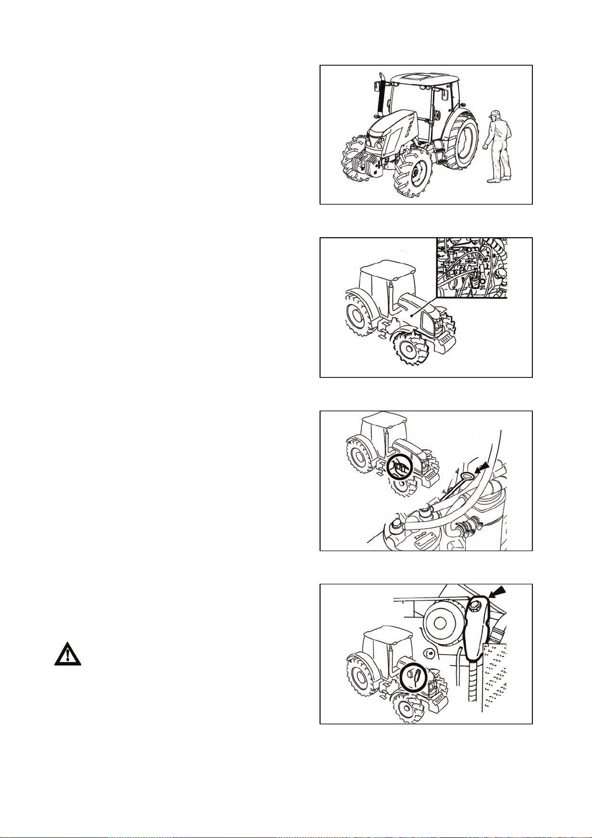
Preventive daily maintenance
PREVENTIVE DAILY SERVICE
23
Perform this maintenance daily or after every 8 - 10 hours
of operation at the latest.
Fuel system leaks
Check the fuel system for leaks, including the fuel tank.
Repair any leaks immediately. The hole for draining dirt
from the fuel tank is found in its bottom.
G4
Engine oil level
After unscrewing and removing the oil dip-stick check the
oil quantity in the engine and then check the connection of
the engine lubrication system for leaks. Maintain the oil
level between the dipstick marks.
Cooling system
Check the connections of the engine cooling system for
leaks and the coolant quantity in the expansion tank.
Replenish the missing quantity up to the upper mark
indicated MAX. The minimum acceptable cooling liquid
level is indicated by the MIN mark.
Only release the overpressure plug when the
coolant has cooled down! There is a danger of
scalding!
P11NC103
E6g
G751a

PREVENTIVE DAILY SERVICE
24
Liquid brakes
Check the liquid brakes for leaks as well as the liquid
control of the clutch and the braking liquid level in the
expansion tank.
Maintain the brake liquid level in the range of 3/4 of the
tank content (max. level) and 1/2 of the tank content
(minimum level).
Trailer brakes
Trailer air brakes
Check tightness of the air system of the brakes and
effectiveness of brakes of the tractor with a trailer.
Trailer hydraulic brakes
Check tightness of hydraulic brakes of the trailer and
effectiveness of brakes of the tractor with a trailer.
G735a
Hydrostatic steering
z Check the oil level in the hydrostatic steering tank.
z Check the tightening of screws and nuts of the steering
rods and levers.
z Check the condition of all the hoses of the hydraulic
steering circuit for damage and for oil leaks.
Air cleaner
If the air cleaner is heavily clogged with dirt, this condition
is indicated by a sensor that lights up an indicator on the
dashboard.
G9
G751b
F_02_6a

PREVENTIVE DAILY SERVICE
25
Cab filtration
Check and if necessary clean the cab ventilation air filters
installed in the front overhang of the roof.
The filter exchange interval depends on the dustiness of
the working environment.
Partial regeneration can be performed by beating out or
blowing with compressed air.
Do the cleaning or replacement of the filter elements after
removing the covering grills in the roof overhang.
At the customer's request we supply filters with active
carbon.
Don't clean the filter; don't flush it with
compressed air.
Hitches
Check the condition of the hitching and attachment
systems of the tractor and trailer.
F_02_9
F18
Inspection of fouling of coolers
Open the front cowl and check the plates of the engine radiator of engine cooling liquid and air conditioning
condenser, the cooler of oil of the front PTO shaft and the cooler of the gear oil (if the tractor is equipped with
them) for fouling.
In case of fouling clean the cooler plates with pressure air.
After work with front implements and in case of cooler clogging
After work with front implements:
- Check the connections of the external hydraulic circuit of
the control of the front three-point hitch for leaks
Clogging of the coolers:
- Release and slide the cooler to the left side of the tractor.
- Clean the front walls of the engine (gearbox, airconditioning condenser) cooler with compressed air (blow
air in the direction from the engine).
- Remove residual dirt from the space under the hood so
that it should not be suctioned again.
C113
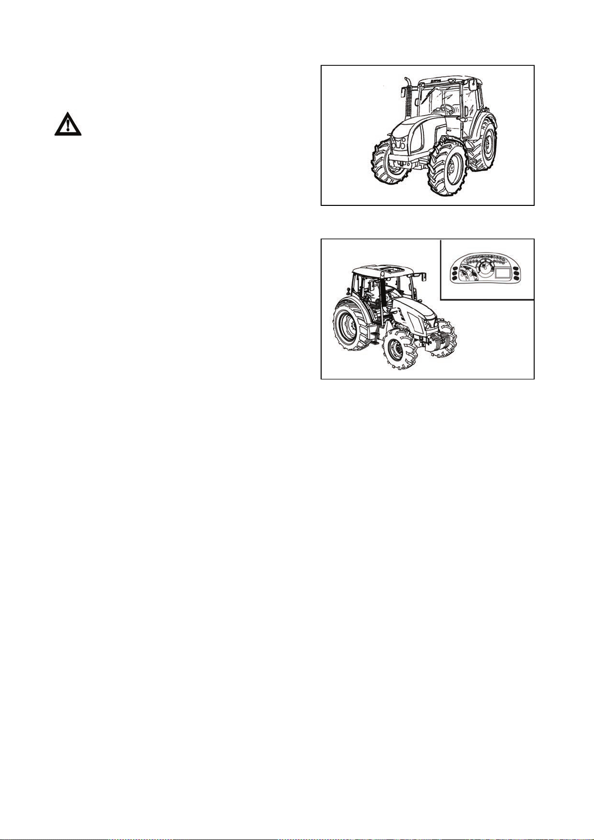
PREVENTIVE DAILY SERVICE
26
Tyres and wheels
Check the air pressure in the front and rear tyres.
Depending on the character of work adjust the pressure to
the recommended value. Check and if necessary retighten
the bolts of the front and rear wheels.
Never drive with loose wheel bolts!
Short functional test
After starting the engine check whether the hydrostatic
steering failure, engine lubrication and charging indicators
have gone off.
Verify the function of the hydraulic steering circuits and
check them for leaks.
G11
P15N032
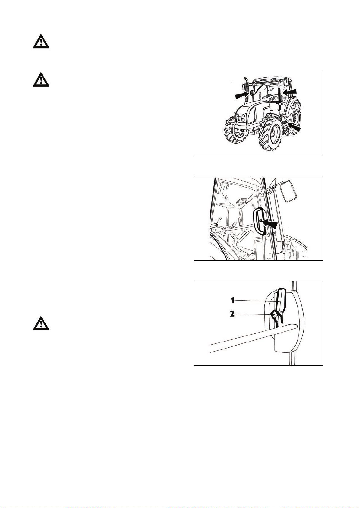
Tractor user must be properly acquainted with recommended operating and safety rules for
p
ACQUAINTANCE WITH TRACTOR
27
safe tractor operation in advance. It is too late to do it within operation!
Safety cab
Use the left side of the tractor for getting in and
off the cab.
Use climbing spurs for getting on and off the cab and
hold onto a handle.
Take greater care in the area of gears lever and
manual fuel control lever.
G101
Opening doors from the outside
Left cabin door is lockable from the outside. Right door of
the cabin are equipped only with a button from the
outside. After unlocking and pressing the button of the
lock the door opens by pulling the handle.
Opening the door from the inside
1. Lever for opening the door from the inside
2. Lever for opening the door from the inside
The door is held by a gas strut with a full opening.
Driving with open door is not recommended for their
possible damage.
It is forbidden driving with open door due to its
ossible damage.
C120
F23
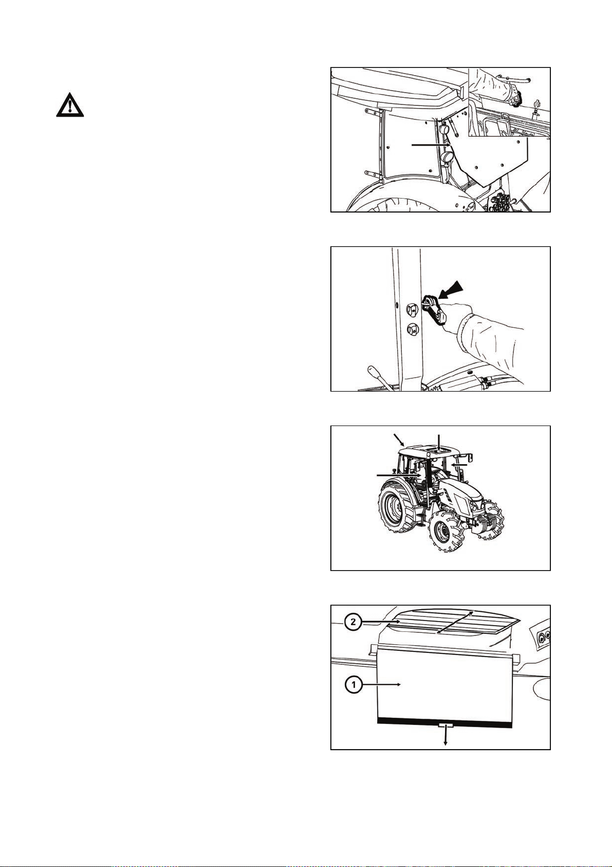
p
ACQUAINTANCE WITH TRACTOR
28
Rear window
Is equipped with a handle and in an open position is
locked by gas spruts. Rear window is heated.
When driving on an uneven surface we
recommend to secure the window in a closed position
- danger of window cracking. Before starting the work
with the machinery Before starting the work with
mounted in three-point hitch of the tractor, make sure
that there is not a danger of collision between the
mounted tools with maximum lifting of rear three-
oint hitch and open rear window. In case of collision
we recommend to work with a closed window.
Side window
The window is secured in the partly open position with
a plastic latch. You can open the door by lifting the latch
towards yourself upwards and pushing it into the groove.
Then, the window will be secured in the fixed position.
C15N025
Emergency exits
In case of overturning of the tractor or block ing the exit
from the tractor use the left or the right door, the rear
opening window or the roof opening window as
emergency exits.
Sun screen
Pull out the adjustable screen of the front window (1) by
pulling the hand rail in the arrow direction.
To return to the original position, shortly pull the hand rail
in the direction of the arrow and release the hand rail.
The sliding cover of the swing lid (2) is closed and opened
with pressure or by pulling the slots in the arrow direction.
C123
P15N085
C15N146
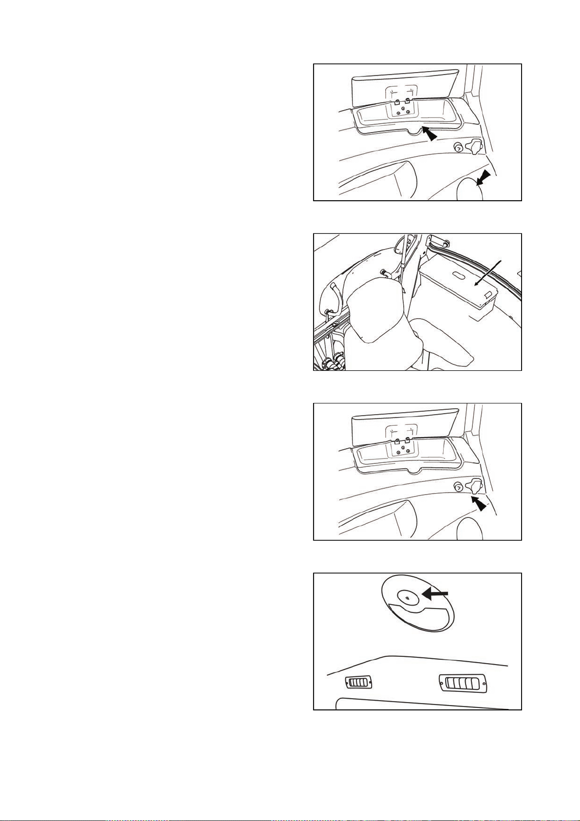
ACQUAINTANCE WITH TRACTOR
29
Shelf
Storage spaces are located on the right mudguard.
Tools box
The tools box is located on the right side of the driver's
seat.
FH12N025
Right rear panel
On the right rear panel there are the three pin socket 12V
and the firer.
Internal lighting
To be turned on and off by means of a button marked with
the arrow.
P15n019
P15n020
F13BN014

ACQUAINTANCE WITH TRACTOR
30
Rear view mirrors
Before the drive or starting the work, adjust rear view
mirrors so that they enable to monitor the whole drive way
or working field.
Aggregation opening
Aggregation opening serves for cabelling or Bowden
control of aggregated tools placement.
Pull to protrude the part of sealing of rear window in
upward direction. Put the aggregated tool control through
the originated hole.
Insert cabelling or Bowden controls to the holes of
passage of aggregation opening. Return the sealing of the
rear window to its original position by exercising pressure.
F_02_12
F11N091
Passenger´s seat
Passenger´s seat is tiltable and placed on the left mudguard of the cabin.
P15N028
Seat tilting out
Passenger´s seat to be tilted out in the direction of an arrow (1) upward. Locking of the seat is done
automatically.
Seat tilting
Lift the passenger´s seat in the direction of an arrow (2), pu ll the lever (3 ) to the direction of the driver´s seat,
tilt the seat in the direction of an arrow (4).

ACQUAINTANCE WITH TRACTOR
31
Driver's seat Mars Svratka
The suspended seat is adjustable for driver's weight from
50 up to 120 kg. Adjustment is done by turning of square
knob. Weight indicator is located in the slot of rear seat
cover. Spring stroke is 120 mm.
Do not adjust the seat when driving! Danger of
accident!
The seat can be longitudinally adjusted within range ± 75
mm (11 positions) after unlocking of left hand side lever.
C131
Vertical seat adjustment is done by the right hand side
lever; from the middle position to two marginal positions
within range ± 30 mm.
C132
C133

ACQUAINTANCE WITH TRACTOR
32
Driver's seat Sears
P13N003
The driver's seat Sears can be made with a mechanical (A) or pneumatic (B) suspension.
1 - The seat suspension adjustment controller according to the driver's weight (turn it in the direction based
on icons shown on the seat bellows)
2 - The seat height adjustment controller (release the controller to increase the seat height, tighten the
controller to decrease the seat height)
3 - The longitudinal seat adjustment lever (pull the lever to adjust the seat lengthwise, return the lever back
to its original position to lock the longitudinal adjustment)
4 - The seat backrest inclination adjustment controller (pull the lever to adjust the seat backrest inclination,
return the lever back to its original position to lock the backrest position)
5 - Foldable armrest
6 - The armrest height locking adjustment (release the controller to adjust the height of the armrest, tighten
the controller to lock the armrest position)
7 - The seat vibration absorption setting (move the controller up to get the float seat position, move the
controller to the lower position to lock it)
8 - The seat height adjustment and seat suspension adjustment according to the weight of the driver (push
the controller to increase the air pressure in the pneumatic suspension of the seat - when the driver´s weight
is bigger, pull the controller to decrease the air pressure in the pneumatic suspension of the seat - at the
lower weight of the driver
Driver´s seat
1 - The control of setting the seat suspension according to
the driver´s weight (setting by rotation, in the direction
according to pictogram on the boot of the seat)
2 - Longitudinal setting of the seat lever
3 - Seat vibrations absorption control (by tilt over of the
control forward, floating position of the seat is engaged)
4 - Setting the angle of rest control
5 - Tilting elbow rest
6 - Pneumatic suspension of seat setting control (by
pulling in the direction upward, the rigidity of the
suspension increases, by pulling in downward direction, it
decreases)
Driver´s seat with mechanical suspension
Control according to points 1, 2, 3, 4 and 5
Point 2, lever is placed on the right
Driver´s seat with pneumatic suspension
Control according to points 2, 3, 4, 5 and 6
Point 2, lever is placed on the left
FH12N026

p
f
(2) by
ACQUAINTANCE WITH TRACTOR
33
Tilt steering wheel
Adjusting the angle of the wheel
The angle can be adjusted by tilting the wheel after it is
unlocked by moving the lever (1) in the direction shown by
the arrow.
After adjusting, lock the wheel by pressing the lever (1) in
the opposite direction than shown by the arrow.
Tilting and protrusion of steering wheel
Tilting column of steering wheel enables variable setting o
position of the steering wheel both in terms of angle and
height.
Height setting of steering wheel
The setting is done by protrusion or retracting the steering
wheel after unlocking arrestment by turning a lever (1) in
the direction of an arrow. After setting the steering wheel,
lock the lever (1) by tightening in the direction of an arrow.
W1
Angle setting of steering wheel
Setting is done by tilting the steering wheel after unlocking
the lock by turning the lever (2) in the direction of the
arrow. After setting the steering wheel, secure the lever
F205
retightening against the direction of the arrow.
When the steering wheel is adjusted, fold th e locking lever (2) to the instrument panel and the
locking lever (1) so that it is directed parallel to the axis of the steering wheel column. After slig ht
ulling of the locking levers in the direction from the steering wheel column, the levers can be set to
any position.

r
ACQUAINTANCE WITH TRACTOR
34
Heating control panel, * ai
-condition
The control panel of the heating and of the air conditioning
is located on the right side of the lower view of the cabin
roof.
A - valve heating controller
B - fan controller
C - air conditioner switch
D - controller of air circulation in the cabin
Heating valve control (A)
a - heating valve closed
b - heating valve opened
F13BN009
Ventilator control (B)
0 - ventilator off
1 - slowly run of ventilator
2 - medium run of ventilator
3 - maximum run of ventilator
Switch air-condition (C)
Do engagement and disengagement of air-condition
system function by switching the switch with a symbol of
snow flake (C).
You will set the air-condition system going by pressing the
switch (the symbol of snow flake lights up).
You will disengage the air-condition system by repeated
press of switch (snow flake symbol switches off).
F_02_16_a
F_02_16_b
F_02_17a

ACQUAINTANCE WITH TRACTOR
35
Air circulation in cabin control (D)
a - Surrounding (outside) air is sucked in through filters to
cabin - sucking the air from cabin is closed.
b - Air is sucked in from the space of the cabin and again
blown off to the cabin (inner air recirculation for fast
adjustment of temperature in the cabin).
The intake of air from the outside of the cabin is
completely locked and there is no surplus pressure in
the cabin which would prevent pervasion of unfiltered
air to the cabin! Do not use this position of the control
with work of the tractor!
Proper function of the heating and air-condition system
It is necessary to create surplus pressure in the cabin for
proper function of the heating or air-condition. We
therefore recommend you to close all the windows and
doors and tilting cover of the cabin.
F_02_17b
Fast heating of the cabin area
Proceed accordingly:
1 - Turn the heating valve control (A) to the position on the
right (fully opened heating valve).
2 - Set air circulation in cabin control (D) to the position of
inner circulation.
3 - Select applicable gear of the ventilator run (position 1,
2, 3) by ventilator control (B).
4 - Set the expiration under the requested angle to avoid
direct fanning of the people in the cabin.
5 - After heating the space of the cabin, set the air
circulation in the cabin control (D) to the position of
sucking the outer air - see fig. F_02_17b position (a)
Fast cooling of the space of the cabin
Proceed accordingly:
1 - Switch the heating valve control lever (A) to the
position to the left
2 - Set the air circulation in the cabin lever (D) to the
position of outer air sucking
3 - Select an applicable gear of the ventilator run (position
1, 2, 3) by ventilator control (B)
4 - Switch the air-condition system by a switch (C)
5 - Set expiration under the requested angle so that direct
fanning of people in the cabin does not occur (the
possibility of illness due tointensive cooling of parts of
body).
F11N009
F_02_18a
F_02_18

r
p
ACQUAINTANCE WITH TRACTOR
36
Operation of heating or ai
-condition with tractor´s work
With engaged inner recirculation of air is the inflow of
fresh air closed and there is foul air in the space of the
cabin by operator. This state can cause the fee lin g of
fatigue and there can also be penetration of dust to the
cabin because of the loss of surplus pressure.
Note: Set the control (D) according to individual
requirements on temperature to the position between (a)
and (b) so that the ventilator sucks the air from the outside
of the cabin through filters, when working.
When spraying pesticides and using the
heating filter with active carbon, the recirculation
controller should be in position 'air is drawn into from
the outside' and the fan controller should be in the
osition 'fan maximum work' to create overpressure
in the cabin.
Immediately after cooling the cabin
Immediately after cooling the cabin and lowering the inner
temperature on the required values, we recommend the
following:
- Switch over the control of air circulation (D) from position
(b - air re-circulation) to position (a - outer air suction)
- Do the continuous regulation of the air temperature with
air condition on by opening the heating valve (A). The air
entering the cabin from expiration is not so intensively
dried with this setting.
- Continuous temperature control with air-condition on can
be also done by lowering the output of ventilator by
switching the control (B) to position 1 or 2.
F_02_19
Air-condition and heating registers (A)
F13BN010
Positionable heating and * air-condition registers, front (A), rear (B).
F_02_20

p
ACQUAINTANCE WITH TRACTOR
37
Front windshield (B) defrosting
To ensure quick defrosting of the front windshield direct
the central heating outlets (1) under the angle of approx.
45° towards the windshield. Direct the side outlets (2)
under the angle of approx. 45° to the cab corners.
After defrosting of the fron t windshield direct the side
outlets to the side glasses of the doors as necessary and
gradually defrost them. After defrosting direct the outlets in
such a way that the air should not be blown directly to the
driver, but down to the driver's legs.
*Air filter with active carbon
F13BN011
F13BN015
Active carbon filters are installed in the placed of standard dust filter and the replacement is done in the
same way as with standard filters. Filter must be inserted with the white side to the grid. Assembly
instructions are found in the chapter 'Maintenance instructions'.
Filter is used only when spraying pesticides, then it must be replaced back by a paper filter because the
flying dust would clog the carbon filter very fast.
The recirculation control must be in the position 'air is sucked from the outside'.
Ventilator control must be in the position 'maximum ventilator run'.
WARNING: filter does not provide full protection against toxic substances
- Wear protective gloves when manipulating with the filter.
- Do not clean the filter and do not blow through with compressed air.
DANGER: Replace the active carbon filter every 200 hours or 36 months (date of production is
given on the filter). If you happen to smell pesticides in the cabin, replace the filter immediately and
have the sealing of the cabin checked. Used filters must be damaged in specialized collection
centres.
When spraying pesticides and using heating filters with active carbon, the recirculation
control must be in the position of 'air sucked from the outside' and the ventilator control 'maximum
ventilator run' for creating surplus pressure in the cabin.
When spraying pesticides, increased care should be taken when entering or exiting the tractor
because of possible contamination of the working area. Follow the safety instructions for handling
esticides according to the valid legislation of the country where the tractor is used, type of the
hazardous substance, instructions of the manufacturer of the hazardous substance and
manufacturer of the carried or towed sprinkler.

r
ACQUAINTANCE WITH TRACTOR
38
Control panel on right cab pilla
PP15N017
Distribution of switches in a tractor of standard construction (A)
1 - switch of the cycler of the front wiper
2 - two-position switch of the front wiper and of the control of the front washer
3 - switch of the rear wiper
4 - switch of heating of the rear wiper
5 - switch of heating of the rear mirrors
6 - switch of the rear work lights on the cabin roof
7 - switch of the front work lights on the cabin roof
8 - switch of the rear PTO shaft
9 - switch of the front PTO shaft
If the tractor is equipped with electro-hydraulics (EHR), the switches (8) and (9) are transferred to the control
panel of the outer hydraulic circuit (B).
Wiper and washer of the front window
The switch of the front wiper and control of the front
washer are located on the right column of the cabin.
The double-speed engine of the front wiper is controlled
by the two-position switch of the front wiper.
The windshield washer is activated after pressin g the
switch of the front double-speed wiper located on the right
column of the cabin. The maximum time of continuous
operation of the washer pump is 20 s.
When the washer is used, the windshield is automatically
wiped by the wiper. The number of wipings depends on
the operation time of the washer.
P15N022
Front wiper speed switch
The front wiper speed switch is turned on using the switch
located on the right column of the cabin.
Setting the wiper cycle period:
Turn on the speed switch, after the front window has been
wiped, turn off the speed switch, wait the required period
between wipes and turn on the speed switch.
The required gap between wipes is automatically set.
P15N023

r
r
ACQUAINTANCE WITH TRACTOR
39
Rear window wipe
The switch of the rear wiper is located on the right column
of the cabin.
The single-speed engine of the rear wiper is controlled by
the single-position switch of the rear wiper.
Washer nozzle
The washer nozzle is situated in the upper part of the
hood and is adjustable by needle or steel wire of
maximum diameter 0,8 mm.
P15N024
Windshield washer tank
Windshield washer tank is placed on the rear wall of the
cabin from the outside side.
The washer tank capacity is 2,5 litres.
In summer the reservoir should be filled with distilled wate
or mixture for washers.
Antifreeze mixture for washers must be used in winter
season for filling the washer tank.
C128
F_02_152a

j
g
)
ACQUAINTANCE WITH TRACTOR
40
Panel of the instrument panel
F13HBN001
a - Lights switch (off, parking, head)
b - Lower beam lights in the grill of the tractor and working lights in the cabin of the tractor switch
c - Fog light switch (off - on). Fog light function is signalized by a lit symbol on the switch.
d - Working lamp switch (off - on). Working lamp function is signalized by a lit symbol on a switch.
e - Warning lights switch
f - Front drive axle button. Engaged front drive axle is signalized by lit symbol on a switch.
g - Beacon switch (off - on)
h - Working lights in the grill of the bonnet switch (off - on)
i - Preselection of torque multiplier switch
- Differential lock button
k - Switch box
l - Direction lights, lower beam head lights, head lights and horn switches acoustic and light
m - Reversin
lever (forward, neutral, backward

ACQUAINTANCE WITH TRACTOR
41
Lights switch
a - illumination off
b - side and end point lights on, illumination of licence
label, illuminated
c - all devices on in 'b' position. Lower beam head lights or
head beam lights are engaged (according to the position
of direction lights, lights and horn switches).
Switch of warning lights
a - warning lights on
b - warning lights off
Function of warning lights is signalized by interrupted
blinking control on the dashboard.
F56
Lights switch between the grill and the cabin
a - roof lights on
b - roof lights off
The switch controls the illumination in the grill or in the
roof of the cabin of the tractor. Use the lights in the roof of
the cabin only when tools covering headlights in the grill is
attached in front three-point hitch. A lit symbol on the
switch signalizes light on in the roof.
Headlights can be lit only in the grill of the bonnet.
Direction lights, lower beam head lights, head lights and horn switches
a - Acoustic horn - press the switch in the direction of an
axis
b - Lower beam head lights
c - Direction lights to the right
d - Direction lights to the left
e - Acoustic horn
f - Lower beam headlights
F58
F59
X139

p
ACQUAINTANCE WITH TRACTOR
42
Front wheel drive switch
Use the front driving axle for increasing the
ulling force of the tractor when rear wheels slip.
a - Front driving axle disengaged
b - Front driving axle engaged
Front driving axle is engaged at stopped tractor (braked
tractor; stopped engine, switch key is switched-of).
In the basic position, the front driving axle is engaged
(indicator lamp is 'ON') and disengaging of the axle is
made with the switch (indicator lamp is 'OFF').
Push button of rear, front differential locks
a - Differential lock disengaged
b - Differential lock engaged
The differential lock is engaged by pressing the differential
lock push button that returns into the previous position
after loosing.
Illuminating of the symbol on the switch indicates that the
differential lock is engaged.
The differential lock is automatically disengaged after
pressing the brake pedals.
At tractors equipped with front driving axle equ i pp e d with
engageable differential lock, this is engaged
simultaneously with the rear differential lock engaging.
a - Pre-selection controller off
b - Pre-selection controller on
C156
C157
Position (b) pre-selection controller on is signalled by a lit
symbol on the controller
If the pre-selection controller is off (a), the gears of
multiplier can be changed by buttons on speed gear lever.
If the pre-selection controller is on (b), the gears of
multiplier can be changed automatically depending on the
engine revolutions according to pre-set values.
Switch box
Switchbox is placed on the dashboard, see arrow.
X102
P15N031

ACQUAINTANCE WITH TRACTOR
43
Switch box key in the position (0)
The voltage of all the equipment controlled via the key is
disconnected. The key can be removed.
Switch box key in the position (I)
The voltage is connected to all the equipment excluding
starter. The key is in this position with the engine running.
S43
Switch box key in the position (II)
Starter and supply of all equipment is connected in this
position apart from wipers, washer, cab ventilator and air
condition. After starting, the key automatically returns back
to 'I' position.
Manual throttle
a - idle run
b - maximum supply
The lever enables to set engine revolutions in the whole
range (a) to (b).
S44
S45
C15N054

ACQUAINTANCE WITH TRACTOR
44
Pedals and levers
1. Travel clutch pedal
2. Foot operated service brake pedals connected by latch
3. Foot throttle pedal
Reversing lever
F - front driving; lever in the front
N - neutral
R - back driving; lever at the back
P15N027
Gear shifting lever
- main gear shifting lever
1. button for disengaging clutch on the head of gear
shifting
2. buttons of shifting individual gears of multiplier
Gear shifting scheme
Reverse can be shifted only using the reversing lever. The
scheme is attached in the left lower corner of the
windscreen.
X212a
FH12N037
E148a

r
g
g
g
gag
p
(
)
ACQUAINTANCE WITH TRACTOR
45
Road and reduced speeds shifting leve
H Road
ears
N Neutral
L Reduced
ears
Shifting is carried out with tractor in standstill.
PTO selection control lever
a - Independent speed of PTO shaft - PTO shaft speed de-
pends upon the en
ine speed
n - Neutral
b - Ground speed of PTO shaft (through gearbox) - PTO
shaft speed depends upon the en
ed gear speed
Shifting is made when the tractor stops.
G150
Lever of shifting of speed 540 (or 540E) and 1,000 rpm of the rear output shaft
Shifting can be carried out when the tractor is in standstill
by pulling up or pushing down the lever.
a b -
1,000 min
540 min
-1
-1
or 540E min
-1
* The tractor can be equipped optionally by 6-, 8- or 21groove termination of the output shaft.
-1
Shifting of 540 and 1,000 (or 540E) min
is
ossible regardless to the number of grooves on the
installed termination. Speed of the output shaft and
type of the termination shall be chosen depending on
G153a
the prescribed speed of the aggregated machine.
Lever of hand brake and hitch for single-axle trailer
1. Hand brake lever.
2. Lever of the single-axle trailer hitch control.
When stopping or leaving the tractor you must
always secure the tractor with the parking brake.
The engagement of a gear does not prevent the
tractor from getting in motion (the clutch is
disengaged)!
If the tractor is standing on a slope, its wheel must be
additionally secured with wedges!
G154
E155

y
ACQUAINTANCE WITH TRACTOR
46
Battery disconnector
During long-time shutdown, repairs, failure or
crash immediatel
disconnect the battery by means of
the battery switch.
Battery switch is located on the left hand tractor side in
front of the cab.
A - battery connected
B - battery disconnected
E157
When the engine is switched off, the engine control unit remains active for about 2 minute
because of storage of operation data. During this time the supply of current from the accumulator
must not be interrupted. Do not disconnect the accumulator before this time expires.
Fuel tank
The fuel tank is fitted at the right-hand tractor side.
A plastic tank of 190 litres volume is mounted as
a standard for all types of tractors.
Do not step on the fuel tank!
Fuel tank drain plug
Plug for draining dirt and fuel off the fuel tank is in its
bottom.
PW15N020
H800

ACQUAINTANCE WITH TRACTOR
47
Urea tank
The tank for urea is located in the right side of the tractor
and is equipped with the blue plug of the filling hole.
The tank volume is 30 litres.
PW15N019

NOTES
48

Instrument panel - signal lamps
INSTRUMENT PANEL
49
C15N093
When switching the key in the switch box from 0 position to 1 position, all signal lamps light up.
1 - Signal lamp of the tractor left direction lamps (green).
2 - High beam lights (blue). Lights up with high beam lights on.
3 - Operational protection signal lamp (blue). It is lit up when there is disagreement between operational
values of the tractor groups.
4 - Signal lamp of direction lights of 1st trailer (green)
5 - Signal lamp of direction lights of 2nd trailer (green)
6 - Minimum air pressure in brake system signal lamp (red). It is lit up with the pressured drop for air brakes
of trailer below the critical limit.
7 - Manual brake signal lamp (red). It is lit with engaged manual brake.
8 - Charging signal lamp (red). With engine run, lights up with charging failure. When the engine is at
standstill, it must be lit.
9 - Lubrication signal lamp (red). With engine running lights up with the oil pressure drop below the critical
limit.
10 - Air cleaner clogging signal lamp (yellow). Lights up with air filter clogging.
11 - Urea level signal lamp (red/orange)
12 - SCR signal lamp (red)
13 - SCR signal lamp (orange)
14 - Indicator (red) of a failure in the hydrostatic control system. It lights with engine operation in hydrostatic
control failure. When the engine is at standstill, it must be lit.
15 - Signal lamp of tractor right direction lights (green).
16 - the signal lamp of the diesel particulate filter. It signalizes the state in two stages: In case of the full
diesel particulate filter it glows in orange. In case of a defect it glows in red.
17 - the signal lamp for indication of optimal conditions for regeneration of the diesel particulate filter. It glows
in the case when the temperature is higher than 250°C (green). It flashes in case that regeneration of the
diesel particulate filter (DPF) is being perf or med .
18 - Engine ignition signal lamp (yellow). Signalizes the activity of the device for facilitation of engine start.
19 - Not connected
20 - Fuel level signal lamp (orange). It is on with the remaining 0 - 1/4 of the tank volume.
21 - Gearbox malfunction signal lamp (dark red)
22 - Warning signal lamp (orange)
23 - Stop signal lamp (red)

INSTRUMENT PANEL
50
Instrument panel - instruments
C15N094
A - coolant thermometer
B - fuel gauge
C - air pressure gauge
D - speedometer
1. Engine revolutions
2. Indicator of engine revolutions at which nominal revolutions of the rear PTO at economic revolutions of the
rear PTO shaft are achieved.
3. Indicator of engine revolutions at which nominal revolutions of the rear PTO at standard revolutions of the
rear PTO shaft are achieved.
E - display
Instrument panel - buttons
A - Rolling up in the menu button
B - Rolling down in the menu button
C - Entry to the menu button, confirming items on the
menu
D - LCD backlight inversion button
E - Reset button hours of operation and km
F - Change of display button in the navigation menu
C15N041

INSTRUMENT PANEL
51
Display description
The following values are displayed on the main display:
1 - shifted gear of multiplier of torque, according to shifted
gear 1 , 2 or 3 is displayed
2 - switching the switch of torque multiplier preselection
3 - engagement of front axle drive switch
4 - engagement of differential locks
5 - maintenance interval exceeded
6 - shifting lever position, reversing F driving forward, N
neutral, R reversing
7 - main field of display
8 - secondary field of display
Change of the look of display
The change of look of display from display (1) to display
(2) can be done by pressing a button (A).
Change in the display contrast
The display contrast of main screens can be changed
using the arrows (A) and (B).
PW15N001
PW15N002
Display - change of display
By repeated pressing of button (A) you can click between
individual displays of data on the display (so called
screens).
P15N067
C15N029

A
INSTRUMENT PANEL
52
When the key in the switch box is moved to position I, the
home screen is displayed on the display.
fter about three seconds the main screen is displayed on
the display.
In the main field (1) the travel speed of the tractor is
displayed. In the secondary field (2) the current time in 24hour format is displayed.
C15N030
There are data regarding PTO shafts in this screen.
1. Front PTO shaft revolutions, if the shaft is activated.
2. Rear PTO shaft revolutions, when the shaft is switched
on.
3. Tractor travel speed.
In the main field (1) the total moto hours worked by the
tractor are displayed.
In the secondary field (2) the total moto hours worked by
the tractor from the last resetting of the data are displayed.
PW15N003
PW15N004
PW15N005

INSTRUMENT PANEL
53
In the main field (1) the total kilometres worked by the
tractor are displayed.
In the secondary field (2) the number of kilometres
travelled by the tractor from the last resetting of the data is
displayed.
In the main field (1) the voltage of the accumulator battery
is displayed.
PW15N006
In the main field (1) the total amount of the fuel consumed
from the engine start is displayed. The entry is
automatically cleared after two hours from the engine
start. In the secondary field (2) the immediate
consumption of the fuel is displayed. The entry is
automatically cleared when the engine is switched off.
In the main field (1) the amount of urea in the tank is
displayed. The amount of the tank value from 100% to
30% is indicated in the main field as (OK), the values from
29% to 0% are displayed continuously as percentage of
the urea tank volume. In case that the data is not available
( -- % ) is displayed.
In the secondary field (2) the average consumption of urea
in grams per hour is displayed.
More information in chapter System of Additional
Treatment of Exhaust Gases.
PW15N007
PW15N008
F15N013

INSTRUMENT PANEL
54
In the main field (1) the number of revolutions of the
engine per minute is displayed.
In the secondary field (2) the engine load in percentage is
displayed.
In the main field (1) the percentage filling of the diesel
particulate filter with carbon black is displayed.
More information in chapter System of Additional
Treatment of Exhaust Gases.
PW15N010
In the main field (1) the time is displayed.
In the secondary field (2) the outdoor temperature is
displayed.
In the main field (1) the average speed of the tractor is
displayed.
In the secondary field (2) the average consumption of the
fuel is displayed.
The entries are automatically cleared after two
hours from the engine shutdown.
P15N065
PW15N011
PW15N028

r
INSTRUMENT PANEL
55
The average speed and the fuel consumption of the tracto
PW15N017
Average speed of the tractor
The average speed of the tractor (1) in km/h from the last reset of the data is displayed on the display.
If you want to determine the average speed for a certain period, you must reset (zero) the value at the
beginning of the measurement.
After the reset, 0 is displayed during first 100 m on the display, then the value is updated every 10 s or 100
m of the distance travelled.
Average consumption of the fuel
The average consumption of the fuel (2) in litres per hour from the last reset of the data is displayed on the
display (2). If you want to determine the average consumption for a certain period, you must reset (zero) the
value at the beginning of the measurement. The value is updated every 10 s.
Manual zeroing (reset) of data
Except automatic zeroing of data, these entries can be zeroed manually.
For manual zeroing of data, the tractor must be with the engine not started and with the key of the switch box
in the position I.
Select display of the corresponding main screen using the button (F).
Zero the entry by longer pressing of the button (E) (RESET).
Attention! Both entries are always zeroed simultaneously; a single entry cannot be zeroed.
Display - resetting data
PW15N012
The procedure for resetting data in the secondary field at the main screens where the data can be reset is as
follows:
Values from the last reset on the display
a - engine hours
b - distance covered
1 - Select display of the corresponding main screen using the button (F).
2 - Reset the entry by longer pressing of the button (E) (RESET).

INSTRUMENT PANEL
56
Display - manual brake
If the tractor is not braked by a manual brake, a warning is
displayed on a display (letter P in a circle) and at the same
time a sound signal is heard. See the chapter "Driving
operation" for more.
Brake the tractor by a manual brake.
Display - indicator of service inspection intervals
FH12N039
PW15N013
The warning regarding an approaching maintenance date (service interval) is displayed if there is less than
30 operating hours remaining to the planned maintenance.
When the key in the switch box is moved to position I, the home screen is displayed on the display (A).
After several seconds the warning regarding an approaching maintenan ce (B) with the number of operating
hours of the tractor (1) remaining to the maintenance date is displayed on the display.
Exceeding the service interval
In case of exceeding the service interval, the maintena nc e
alert is displayed on the display when the key in the switch
box is moved to position I.
When the display is switched to the main screen using
button (F) (DISP), the symbol (1) remains on all displays
of the main screens.
PW15N014

y
INSTRUMENT PANEL
57
Zeroing (reset) of the indicator of service inspection intervals
PW15N023
When the maintenance was performed, zero (reset) the indicator of service inspection
intervals.
Enter the service menu by longer pressing of the button ( A ).
Use the buttons ( B ) and ( C ) to select the item calibration indicated with the arrow ( a ). By pressing the
button ( A ) you enter the calibration menu.
Use the buttons ( B ) and ( C ) to select the item service indicated with the arrow ( b ). By pressing the button
( A ) you enter the service menu.
Use the buttons ( B ) and ( C ) to select the item [clearing] indicated with the arrow ( c ). By pressing the
button ( A ) reset the indicator of the service interval.
To return to the service menu, use the buttons ( B ) and ( C ) to select the item EXIT and press the button
( A ) (Enter).
Error signalling
Errors arising during tractor operation are indicated by
switching the corresponding signal lamp, acoustic signal
and error message in the instrument panel display.
If the error is indicated, the signal lamp still glows, even
though the display is switched to the next display.
If the error is not eliminated or the indicated state has not
returned to a normal state:
the corresponding signal lamp glows
when the tractor is switched off, the key in the switch box
is moved to position I and then the engine is started, the
corresponding signal lamp is switched on again and the
error message runs through the display.
1 - The signal lamp of a serious defect of the system (red).
2 - The signal lamp of a less serious defect of the system
(orange).
3 - Operational protection signal lamp (blue).
4 - Gearbox malfunction signal lamp (dark red). It glows
together with any of the signal lamps indicating errors, as
long as the error relates to the gearbox or the system of
travelling clutches.
During tractor operation, three types of error messages
appear in the display.
ma
C15N111

INSTRUMENT PANEL
58
Display - error messages
C15N057
During tractor operation, three types of error messages may appear in the display.
A. - Warning of operational protection,
that a small deviation from the set values or error by the operator occurred.
The warning is displayed in the display for about 10 seconds and then the display is switched to the
previously set main screen.
The state is indicated by the signal lamp
The tractor can be used without limitation.
B. - Less serious defects of the system
If a less serious defect of the system occurs, the defect nu mbe r is displa ye d in th e display for about 10
seconds. Then the display of the defect is minimized into the main fie ld.
All the tractor's functions remain active; it can happen that some of the functions is not undepreciated.
The state is indicated by the signal lamp
If this situation occurs, finish the work and contact the service centre.
C. - Serious defects of the system
If a serious defect occurs, the display is backlighted in red there is a label STOP. The display cannot be
switched to another screen.
The state is indicated by the signal lamp
If this situation occurs, stop the tractor immediately and contact the service ce ntre.
Description of the display of error messages
1 - The symbol of the defect significance.
2 - Node of the tractor where the defect appeared.
3 - Main display field - defect code.
4 - Secondary display field - defect specification.
C15N056

INSTRUMENT PANEL
59
Symbols of tractor nodes
Engine
Gears and travelling clutches
System of treatment of exhaust gases
Systems facilitating start of the engine
Display - service menu
Entry to service menu:
You will enter the service menu by a longer pressing of (A)
button.
The selection of items to be done by (B) and (C) buttons.
The selected item is marked by an arrow (1).
Exit from service menu:
By buttons (B) and (C), select an item EXIT and press (A)
button.
Service menu
Service menu
1 - Failures history, for servicing purposes
2 - Machined area
3 - Calibration
4 - Language selection
5 - Exit service menu
P15N047
P15N046

INSTRUMENT PANEL
60
Display - history of defects
PW15N026
a - enter the service menu
use buttons (A) and (B) to select the item listing of defects and press button (C) (ENTER)
b - selection of tractor nodes
use buttons (A) and (B) to select the tractor node from which the listing of defects is needed and press button
(C) (ENTER)
1 - engine
2 - gears and travelling clutches
3 - system of treatment of exhaust gases
4 - system facilitating start of the engine
5 - return to the previous screen
c - the listing of defects of the selected tractor node; use buttons (A) and (B) to scroll between individuals
defects
1 - sequence number
2 - defect code
3 - code of defect specification
4 - number of defect repetitions
Return to the main screen by pressing button (C) (ENTER)
Display - setting language mutation
Enter the service menu:
Use buttons (B) and (C) to select the item LANGUAGE
and press button (A) (ENTER).By successive pressing of
button (A) (ENTER), available language mutations are
successively displayed. When reaching the required
language mutation, exit the service menu.
Use buttons (B) and (C) to select the item EXIT and press
button (A) (Enter).The instrument panel is switched to the
selected language mutation.
If you want to change metric units to Anglo-
Saxon, select the language mutation ENG. IMP.
P15N049

INSTRUMENT PANEL
61
Display - setting and calibration
PW15N018
Enter the service menu by a longer pressing of button ( A ):
a - Use buttons ( B ) and ( C ) to select the item calibration indicated with arrow.
b - By pressing button ( A ) you enter the calibration menu.
1 - calibration of travelling clutches
2 - calibration of travel speed
3 - setting of the display of the rear PTO shaft speed
4 - service setting
5 - setting of hours
6 - return to the main screen
Travel speed calibration
PW15N024
Dashboard is calibrated after assembly at a production plant.
Do repeated calibration in the following cases:
- after a significant wear of tyres
- when mounting new tyres
- when replacing dashboard
Calibration procedure
- at a suitable place, mark a track of 100 m at length
- inflate tyres of tractor on the prescribed pressure, see tables of this Instructions manual
- start the engine
- move the tractor to the beginning of the 100-metre track
- enter the service menu by pressing (A) button
- select the item (1) by (B) and (C) buttons and by pressing (A) button go to calibration menu
- select the item (2) by (B) and (C) buttons and move to the speed menu by pressing (A) button
- select an item (4) by (B) and (C) buttons and by pressing the (A) button, move to the following menu. The
item (3) serves only for setting the travelling speed in the production plant
- select an item (5) by (B) and (C) buttons and confirm with the (A) button
- start the tractor with a stable speed of approximately 10 km/h
- after travelling the whole distance of 100 m stop the tractor at the marked end of the track (b)
- select the item (6) by pressing the buttons (B) and (C) and by pressing (A) button, save the newly read
values and you will return to initial screen
- if calibration of travelling speed did not run properly, error report will appear on the display (7), after
confirming the item (8) you will return to initial screen by pressing the (A) button without saving the new
values

INSTRUMENT PANEL
62
Setting of the display of the rear PTO shaft speed
PP15N025
By pressing button (A) enter the service menu
a - Use buttons (B) and (C) to select the item CALIBRATION indicated with arrow (a) and by pressing button
(A) (ENTER) you enter the CALIBRATION menu
b - Use the buttons (B) and (C) to select the item SETTING OF PTO SPEED indicated with the arrow (b) and
by pressing the button (A) (ENTER) you enter the next screen
c - Screen for setting the rear PTO shaft speed Use the buttons (B) and (C) to select the corresponding shift
speed of the PTO shaft. Confirm the setting with the button (A) (ENTER).
The correct shift PTO speed must be chosen for proper display of the PTO speed!

y
INSTRUMENT PANEL
63
Setting of time
PW15N025
By pressing button (A) enter the service menu
a - Use buttons (B) and (C) to select the item CALIBRATION indicated with arrow (a) and by pressing button
(A) (ENTER) you enter the CALIBRATION menu
b - Use buttons (B) and (C) to select the item SETTING OF TIME indicated with arrow (b) and by pressing
button (A) (ENTER) you enter the next screen
c - Setting time screen
1 - Setting of hours
2 - Setting of minutes
3 - Store and return to CALIBRATION menu (b)
4 - Return to CALIBRATION menu (b) without saving
5 - Display of hours
6 - Display of minutes
Procedure for setting of time
Use buttons (B) and (C) to select the item hours (1); by successive pressing of button (A) (ENTER) we
change the value of hours in the display; changes are displayed directly in the position (5).
Use buttons (B) and (C) to select the item minutes (2); by successive pressing of button (A) (ENTER) we
change the value of minutes in the display; changes are displayed directly in the position (6).
Use buttons (B) and (C) to select the item STORE AND RETURN (3) to confirm changes in the setting of
time and for the return to the CALIBRATION menu or select the item RETURN (4) to return to the
CALIBRATION menu without saving the time setting and confirm it by pressing button (A) (ENTER).
If the accumulator batter
of the tractor is disconnected for a longer time, ca. after ten days the
set time is reset (zeroed). When accumulator battery is connected, the current time must be set
again.

INSTRUMENT PANEL
64
System of treatment of exhaust gases - setting
The regeneration of the diesel particulate filter in case of increased temperature of exhaust gases is
performed at higher engine load. The system of regeneration of the diesel particulate filter DPF can be
controlled through the menu of the engine setting on the instrument panel. The regeneration can be
controlled in two modes. The mode of automatic regeneration of the diesel particulate filter and inhibition of
regeneration of the DPF filter (for safety reasons only).
Enter the menu of the engine setting by long pressing the button (A) on the instrument panel. The service
menu screen (b) is displayed. To enter the engine setting (c), ch oose the corresponding tab using the
buttons (B) and (C) and confirm it by longer pressing the button (A). The following items are displayed on the
screen:
1 - Automatic regeneration of the diesel particulate filter - EAT REGENERATION AUTO
2 - Inhibition of regeneration of the diesel particulate filter - EAT REGENERATION INHIBIT
Note: Setting of individual modes is described in Chapter System of Treatment of Exhaust Gases.

INSTRUMENT PANEL
65
Instrument panel - warning
Replenish fuel
When the fuel signal lamp (orange) is lit up, the prompt to
refill the fuel appears in the display for about 3 seconds. If
the fuel is not refilled, the prompt always appears in the
display when the key is moved from the position ´0´ to the
position ´I´ for about 3 seconds. The fuel signal lamp is
permanently on.
Add urea
F15N012
S15N019
The amount of urea in the tank is displayed on the corresponding main screen (b) in percentage of the urea
tank volume. Small amount of urea in the tank is indicated on the instrument panel (a) by the signal lamp of
low urea level (1). The signal lamp of low urea level is activated simultaneously with one of the following
signal lamps: operational protection (2), defect (3) or stop (4) and the prompt to refill urea in the tank appears
in the display of the instrument panel (c) together with an acoustic signal.
Always refill the urea tank during refueling.

INSTRUMENT PANEL
66
High temperature of the cooling liquid
C15N112
High temperature of the cooling liguid is indicated in several stages of warning
A - informative - reduce the engine power
B - warning - stop the tractor, set the engine to idling until the temperature of the cooling liquid is reduced
C - caution - stop the engine, wait until the temperature of the cooling liquid is reduced and check the level of
the cooling liquid; if the cooling liquid starts to be overheated again when the engine is started, stop the
engine and contact the service centre
If high temperature of cooling liquid is indicated (warning), the reaction of the system is
reduced engine power by 25%.
High oil temperature in the gearbox
C15N118
High temperature of the gear oil is indicated in several stages of warning
A - informative - reduce the engine power
B - warning - stop the tractor, set the engine to idling until the temperature of the gear oil is reduced
C - caution - stop the engine, wait until the temperature of the gear oil is reduced and check the level of the
gear oil; if the gear oil starts to be overheated again when the engine is started, stop the engine and contact
the service centre

r
INSTRUMENT PANEL
67
Full pushing filter of the gearbox distributo
C15N121
The full oil filter of the gearbox distributor is indicated in several stages of warning
A - informative - it will be necessary to perform replacement of the oil filter cartridge of the gearbox distributor
(see chapter Maintenance Guidelines)
B - warning - it is necessary to perform replacement of the oil filter cartridge of the gearb ox distributor (see
chapter Maintenance Guidelines)
C - caution - perform immediate replacement of the oil filter cartridge of the gearbox distributor (see chapter
Maintenance Guidelines)
Full pushing filter of the hydraulics
C15N122
The full oil filter of the hydraulics is indicated in several stages of warning
A - informative - it will be necessary to perform replacement of the oil filter cartridge of the hydraulics (see
chapter Maintenance Guidelines)
B - warning - it is necessary to perform replacement of the oil filter cartridge of the hydraulics (see chapter
Maintenance Guidelines)
C - caution - perform immediate replacement of the oil filter cartridge of the hydraulics (see chapter
Maintenance Guidelines)

NOTES
68

The tractor is equipped with the engine fulfilling emission limits STAGE IV and TIER 4f. The compliance with
SYSTEM OF ADDITIONAL TREATMENT OF EXHAUST GASES
69
the emission limit is achieved, among others, by the combination of two systems of treatment of exhaust
gases:
a - Diesel Particulate Filter (DPF) designed for purification of exhaust gases. In the diesel particulate filter,
solid particles (carbon black) formed during incomplete combustion of diesel fuel are gathered and then
burnt. The oxidation catalyst (DOC) is a part of the DPF unit as well.
b - SCR - the SCR abbreviation stands for system for cleaning of exhaust gases of diesel engines using the
selective catalytic reduction decreasing the amount of NOx in the exhaust gases. At the same time, the
reduction agent injected into the exhaust system reacts in SCR catalyst with NOx emissions contained in
exhaust gases which are reduced to nitrogen (N2) and water (H2O). The control of the injected amount of
urea is performed using the control unit itself in connection with the control unit of the engine.
To ensure proper functioning of the system, several its parts are monitored so to meet the
required emission limits:
- The level and quality of urea injected in the catalyst SCR.
- The amount of NOx in exhaust gases and temperature in the system.
- Detection of an illegal intervention and any handling to put the system out of order.
1. Filter of solid particles (DPF; diesel particulate filter)
2. Oxidation catalyst (SCR)
3. Urea tank (AUS 32, DEF)
S15N026

Conditions for DPF operatio
n
SYSTEM OF ADDITIONAL TREATMENT OF EXHAUST GASES
70
When the tractor is operated, the diesel particulate filter is fouled with solid particles during the fuel
combustion while the engine is running. The regeneration of the diesel particulate filter in case of increased
temperature of exhaust gases is performed at higher engine load. The regeneration of the DPF filter is
supported by evaporation of diesel fuel into the piping of the exhaust system through the oxidation catalyst.
Indication of operation of the full diesel particulate filter is indicated by the pair of signal lamps
(green and orange/red) on the instrument panel. Activation of the green signal lamp indicates that there are
optimum conditions for regeneration of the diesel particulate filter. Flashing of the green signal lamp indicates
that regeneration of the diesel particulate filter is being performed. Defects of the system of the diesel
particulate filter when the engine is running are indicated by switching the red signal lamp on the instrument
panel, corresponding error message on the display together with an acoustic signal.
A short-term activation of the red signal lamp without the subsequent acoustic signal does not
mean indication of the defect.
During operation of the tractor with a low engine load, e.g. during a long-term operation at idling, the risk that
the diesel particulate filter becomes full is higher. While the engine is running, this state is indicated by
activation of the orange signal lamp of the diesel particulate filter, by the subsequent acoustic signal and by
the corresponding error code on the display of the instrument panel. If this situation occurs, increase the
engine load and continue in your work until the orange signal lamp of the diesel particulate filter is
deactivated and the acoustic signal stops. By increasing the engine load the temperature of exhaust gases is
increased and the solid particles blocking the diesel particulate filter are combusted. The conditions suitable
for regeneration of the filter of solid particles DPF while the engine is running are indicated by activation of
the green signal lamp on the instrument panel.
The increased engine load means the operation of the tractor at higher revolutions of the
engine with attached implements, consumption of the power through the take-off shaft or outer
hydraulic circuit; increasing the engine speed of the standing tractor is not sufficient.
The time necessary to decrease the DPF resistance depends on the engine load and how
much the DPF filter is full.
There are high temperatures achieved during regeneration of the DPF filter. Great care should
be taken when the tractor is operated in a flammable environment!
Do not stop the engine during regeneration of DPF (the green signal lamp flashes) - there is
a risk of damage of the system of treatment of exhaust gases. Do not stop the engine immediately
after regeneration of DPF filter.Leave the engine idling at low revolutions until sufficient decrease of
temperature of the system of treatment of exhaust gases is achieved!

Error signalling of DPF syste
m
p
.
SYSTEM OF ADDITIONAL TREATMENT OF EXHAUST GASES
71
Defects of the system of the diesel particulate filter when the engine is running are indicated by
glowing or flashing of the orange / red signal lamp on the instrument panel and by the subsequent acoustic
signal. If the error is not eliminated, it is indicated every time when the engine is started.
During operation there may be a situation when the pressure exceeds the set value for a short
time. This state is indicated by a short-time activation of the orange / red indicator light of the DPF
filter on the instrument panel. It is not an error. Errors are always indicated by the red indicator light
of the DPF filter, acoustic signal and indication activated on the instrument panel.
type of
indication
warning
(regeneration
necessary)
warning
(regeneration
necessary)
1st degree of
limitation
2nd degree
of limitation
Conditions for SCR system operation
The amount of urea in the tank is displayed on the instrument panel. If the amount of urea in the tank is
exhausted when the engine is running, the injector in the exhaust manifold is in danger of being damaged
and the engine power can be reduced. The catalytic reduction is stopped and the amount of harmful
emissions in exhaust gases is increased. When urea is added in the tank, the catalytic reduction is restored.
DPF signal lamp defect signal
signal lamp colour
orange
signal lamp
activated
orange
signal lamp
flashes (0.5
Hz)
orange
signal lamp
flashes (0.5
Hz)
red signal
lamp
flashes (0.5
Hz)
lamp
acoustic
signal
2 x 3 s
Operation of the tractor without the SCR (selective catalytic reduction) system is prohibited!
Conditions for proper functioning of the system
- temperature of cooling liquid must be higher than 60°C,
- working temperature of the catalyst must be higher than 250°C
- outdoor temperature must be higher than -20°C,
- engine revolutions must be higher than 1,000 rpm
- requirement for the withdrawn torque must be higher than 20%.
If urea freezes, the tank is electrically heated. If no melting during 70 min occurs, the engine
ower together with the corresponding error message are activated

Urea (Aqueous Urea Solution AUS 32, DEF)
p
.
SYSTEM OF ADDITIONAL TREATMENT OF EXHAUST GASES
72
The used reagent is a mixture of 32.5% solution of synthetic urea and demineralized water. It is used as
a reducing agent NOx for additional treatment of exhaust gases by SCR (selective catalytic reduction) of
motor vehicles with diesel engines.
The product is labelled as Urea or AUS 32 (AUS: Aqueous Urea Solution) and complies with the standard
ISO 22241-1 Reducing agents NOX AUS 32.
The urea solution AUS 32 is known in USA and North America as Diesel Exhaust Fluid (DEF).
The lifetime of urea without the loss of the quality is influenced by storage conditions.
It crystallizes at ambient temperature below -11°C and at ambient temperature over +35°C it initiates
hydrolytic reaction which means that a slow decomposition to ammonia and carbon dioxide begins.
It is essential to protect unprotected vessels from direct sunlight.
Barrels must not be stored longer than one year!
Pay attention to the resistance of the used materials and store vessels.
Urea freezes below the temperature of -11°C.
To ensure proper functioning of the SCR system, urea with the concentration of 32.5% must be
used!
Principles for safe handling of urea (AUS 32, DEF)
Contact with skin
- Prolonged or repeated contact may cause skin irritation.
Contact with eyes
- Prolonged or repeated contact may cause eye irritation. Rinse eyes with plenty of water for at least 15
minutes. If irritation persists, visit a physician.
Ingestion
- In case of ingestion of small quantities, toxic effects are not likely. Higher amount may cause intestinal or
stomach problems. Do not induce vomiting. Drink half a litre of water or milk. In case of ingestion of a larger
than small quantity, visit a physician.
Fire-fighting measures
- The product has fire extinguishing properties.
Extinguishing means
- If the material got in the fire, use large amount of water for extinguishing.
Accidental release measures
- Minimize contact of the spilled material with the soil so that you do not allow product to reach surface or
underground water courses.
- Soak u
the spilled material with dry soil, sand or other non-flammable material

Error signalling of SCR syste
m
SYSTEM OF ADDITIONAL TREATMENT OF EXHAUST GASES
73
Defects of the SCR system when the engine is running
are indicated by glowing of the orange (1) or red (2) signal
lamp on the instrument panel and by the subsequent
acoustic signal. If the error is not eliminated, it is indicated
every time when the engine is started. The reason for the
indication may be in not meeting the required amount of
NOx in exhaust gases, defect of the urea injection system
or bad urea quality. According to the severity of the error
message, the warning signal lamp (3) or the stop signal
lamp (4) are activated together with the signal lamps (1,
2).
If there is an unprofessional intervention in the
system of selective catalytic reduction, an error is
indicated and the system is switched into an
emergency operation mode of the tractor with
a reduced engine power.
type of
indication
urea signal lamp defect
signal lamp colour
signal lamp
acoustic
signal
warning orange 1 x 1 s
1st degree
orange 1 x 1 s reduction of power by 25%
of limitation
2nd degree
red 2 x 3 s reduction of power by 50%,
of limitation
Indication of amount of urea in the tank
S15N011
reduction of the engine power and
engine revolutions
reduction of max. engine
revolutions to 1,250 rpm
S15N019
The amount of urea in the tank is displayed on the display. If the urea level is higher than 33%, it is displayed
as OK on the instrument panel. If the amount is below 33%, the real amount of urea in percentage is
displayed. Small amount of urea in the tank is indicated on the instrument panel (a) by the signal lamp of low
urea level (1). The signal lamp of low urea level is activated simultaneously with one of the following signal
lamps: operational protection (2), defect (3) or stop (4) and the prompt to refill urea in the tank appears in the
display of the instrument panel (c) together with an acoustic signal.
Always refill the urea tank during refueling.

type of
SYSTEM OF ADDITIONAL TREATMENT OF EXHAUST GASES
74
indication
amount of
urea in
the tank
urea signal lamp display -
signal
lamp
display
type
prompt to
refill urea
defect
signal
lamp
acoustic
signal
reduction of power
and limitation of
engine revolutions
1st degree
of warning
2nd degree
of warning
3rd degree
of warning
1st degree
of limitation
less than
20%
less than
15%
less than
10%
less than
5%
orange
signal
lamp
activated
orange
signal
lamp
flashes
(0.5 Hz)
orange
signal
lamp
flashes
(0.5 Hz)
orange
signal
lamp
flashes
(1 Hz)
short-time
display
(3 s)
short-time
display
(3 s)
Continuous
display
(The prompt
disappears
after
pressing
any button
on the
instrument
panel.)
Continuous
display
(The prompt
disappears
after
pressing
any button
on the
instrument
panel.)
1 x 1 s
1 x 1 s
2 x 3 s
2 x 3 s reduction of power
by 25%
2nd degree
of limitation
less than
3%
red signal
lamp
Continuous
display
2 x 3 s reduction of power
flashes
(2 Hz)
Indication of DPF and SCR errors on the display of the instrument panel
Error messages with the signal lamps and acoustic signal
are accompanied by indication on the display of the
instrument panel.
1 - The symbol of the defect significance.
2 - Node of the tractor where the defect appeared.
3 - Main display field - defect code.
4 - Secondary display field - defect specification.
5 - Service symbol.
Note: More information in chapter Instrument Panel
by 50%, limitation of
max. engine
revolutions to ca.
1,250 rpm)
S15N044

Reduction of the engine power and engine revolutions
SYSTEM OF ADDITIONAL TREATMENT OF EXHAUST GASES
75
If there is a serious error in the system or if the level of urea in the tank is low, the reaction of the system is
reduced engine power output and revolutions. According to the error type, so-called one-stage or two-stage
reduction of engine output is performed.
stage 1 reduction of power by 25%
stage 2 reduction of power by 50% and limitation of
max. engine revolutions to ca. 1,250 rpm
A serious error can be caused by unauthorised interference in the system of treatment of
exhaust gases!
S15N045
If the first phase of the reduced engine power and engine revolutions is approaching, it is indicated for the
tractor operator on the display of the instrument panel (1) or (2) together with an acoustic signal and
indication of signal lamps. After the transitional period of 10 h for Stage IV (97/68/EC) or 1.5 h for Tier 4f
(EPA) expires, limitation of the engine power with continuous starting is activated.
Note: A warning message on the display (1) or (2) is displayed according to the type of the tractor.
S15N046
If the serious error is not eliminated, the second phase of the reduced engine power and engine revolutions
is performed. It is indicated to the tractor operator on the display of the instrument panel (1) or (2) together
with an acoustic signal and indication of signal lamps. After the transitional period of 10 h for Stage IV
(97/68/EC) or 2.5 h for Tier 4f (EPA) expires, limitation of the engine power with continuous starting is
activated.
Note: A warning message on the display (1) or (2) is displayed according to the type of the tractor.

Signalling of whether DPF is full
p
.
SYSTEM OF ADDITIONAL TREATMENT OF EXHAUST GASES
76
Information whether DPF is full is available on the main screen of the display.
S15N019
By repeated pressing of button (A) you can switch between individual screens to the screen with the data on
the status how much the DPF filter is full:
1 - percentage filling of DPF with carbon black
The position (1) indicates the percentage filling of DPF filter with carbon black that fills the filter during
combustion of diesel fuel. This carbon black is combusted during regeneration of the filter and ash is formed.
The ash cannot be removed from the diesel particulate filter using a common regeneration. At higher
percentage filling of DPF filter with ash, intervals between DPF regenerations are shortened.
Note: If the information how much the filter is full is not available, ( --- ) is displayed on the display instead of
percentage values.
At higher percentage filling of DPF filter with ash please contact authorized service.
Long-term shutdown of tractor
During a long-term shutdown of the tractor, the urea filling must be drained from the tank.
Before operating the tractor, the urea tank must be filled with a new filling again and the urea filter element
must be replaced and the urea tank must be refilled with fresh material.
The urea filling should not stay in the tank longer than four month and then it should be
replaced.
Repairs and maintenance of the system of additional treatment of exhaust gases
The system requires use of permissible operating fluids which are referred to in this manual In case of
signalling errors in the system of additional treatment of exhaust gases proceed according to instructions
contained in this manual or contact authorized service.
All repairs and maintenance of the system of additional treatment of exhaust gases must
always be performed by a professional service All interventions in the system, except authorized
service, are
rohibited

System of treatment of exhaust gases - settin
g
SYSTEM OF ADDITIONAL TREATMENT OF EXHAUST GASES
77
The regeneration of the diesel particulate filter in case of increased temperature of exhaust gases is
performed at higher engine load. The system of regeneration of the diesel particulate filter DPF can be
controlled through the menu of the engine setting on the instrument panel. The regeneration is operated in
two modes: The mode of automatic regeneration of the diesel particulate filter and inhibition of regeneration
of the DPF filter (for safety reasons only).
S15N023
Enter the menu of the engine setting by long pressing the button ( A ) on the instrument panel. The service
menu screen ( b ) is displayed. To enter the engine setting ( c ), choose the corresponding tab using the
buttons ( B ) and ( C ) and confirm it by longer pressing the button ( A ). The following items are displayed on
the screen:
1 - Automatic regeneration of the diesel particulate filter - EAT REGENERATION AUTO
2 - Inhibition of regeneration of the diesel particulate filter - EAT REGENERATION INHIBIT
Automatic regeneration of the diesel particulate filter - EAT REGENERATION AUTO
The mode of automatic control of the treatment of exhaust gases. The regeneration of the filter is started in
case of need when a certain level of filling of the filter with carbon black, temperature of exhaust gases and
engine load are reached.
Flashing of the green signal lamp indicates that regeneration of the diesel particulate filter is
being performed.
S15N021
EAT REGENERATION AUTO is set in the menu for setting the engine ( b ). After entering the tab, choose
the corresponding item using the buttons ( B ) and ( C ). Confirm the mode of automatic control of the filter
regeneration ( b ) by long pressing the button ( A ). During operation of the tractor the filter regeneration is
indicated by activation of the signal lamps of the diesel particulate filter on the instrument panel and by the
subsequent acoustic signal. If the filter is regenerated, the green signal lamp of DPF is on. An approaching
defect of the system is indicated by activation of the yellow signal lamp of DPF and if the defect of the
system occurs, the red signal lamp of DPF is activated.
For proper functioning of the diesel particulate filter it is necessary to set the system of
treatment of exhaust gases to the mode EAT REGENERATION AUTO, unless working conditions
require inhibition of the system for safety reasons!

Inhibition of regeneration of the diesel particulate filter - EAT REGENERATION INHIBI
T
g
!
SYSTEM OF ADDITIONAL TREATMENT OF EXHAUST GASES
78
The function of inhibition of regeneration of the diesel particulate filter (EAT REGENERATION INHIBIT) is
used to block the process of DPF regeneration for safety reasons only during operation of the tractor in
a flammable environment (e.g. storage of hay or straw).
S15N022
EAT REGENERATION INHIBIT is set in the menu for setting the engine ( b ). After entering the tab, choose
the corresponding item using the buttons ( B ) and ( C ). Activate the mode of inhibition of the filter
regeneration ( b ) by long pressing the button ( A ). Successful activation is indicated by the activated symbol
(c) in the upper right corner of the instrument panel display. In case that the regeneration must be started,
a maintenance symbol is activated simultaneously with the symbol of regeneration inhibition.
Long-term inhibition of regeneration (in the order of several hours) causes that the DPF filter
becomes full and subsequently the engine power is decreased!
The function of inhibition of DPF regeneration should be active for safety reasons only. After
the period when the regeneration must be inhibited has expired, immediately set the mode of DPH
automatic re
eneration

Before a drive with the new tractor get to know how to shift gears and try individual positions
p
y
p
OPERATION
79
of the shifting lever when the engine is stopped.
During normal operation and before you set up, make sure that the technical condition ensures safe
operation of the tractor.
Before you start the engine
Before you start the engine, make sure:
1. that the tractor is properly braked
2. that the main gear shifting lever is in the neutral
osition
3. that the reversing lever is in the neutral position
4. that the PTO switches are off.
If the clutch pedal is not pressed - the engine cannot be
started - the starting interlock switch is not actuated.
Note: Before the entire starting we recommend you to
prime the fuel system with some strokes of the manual
feed pump.
Non-permitted starting
It is forbidden to start the tractor by short-
circuiting the starter clamps. Start only from the
driver´s seat. It is necessar
to disconnect minus pole
of accumulator and all the shifting levers including
PTO shaft shifting lever to be shifted in neutral
osition with any manipulation or repair of the starter.
The starter´s clams are covered with a cap.
*Coolant heater
Is mounted on the right side of engine block.
output 1,000 W
voltage 220 V
PW15N029
C15N125
C209

r
g
p
OPERATION
80
Starting the engine while using coolant heate
G210a
With low temperatures of the surroundings, engine starting eases heating coolant. Leadin electrical
installation and its protection against dangerous contact must be done pursuant to valid regulations
1. First plug the plug to the heater.
2. Then connect heater to electrical network of the voltage of 220 V.
With regard for the lower engine wear with low temperature, the use of heater is recommended by
manufacturer. The duration of heating is dependent on the surrounding temperature (1 - 2 hours before the
expected start).
After completing the heating, disconnect the device first from electrical network and only then
disconnect the plug from the heater! Danger of injury due to electricity!
It is necessary to ensure tractor operator's instruction and regular revision of coolant heater
includin
feeding cable pursuant to valid legislation of the state where the tractor is operated at least
rior to each winter period.
Starting the engine
PW15N030
1. Put the key in ignition - '0' position.
2. Make sure the parking brake is set.
3. Switch off PTO.
4. Depress the clutch pedal.
5. Move the reversation lever located under the steering wheel the the neutral position.
6. Move the gear lever to the neutral position.
7. Turn the key to 'I' position. The glow plug indicator illuminates.
8. Wait till the glow plug indicator goes out (the time depends on the temperature of the liquid coolant).
system (Ignition system error singals chapter). Have the error repaired in a specialized service
station.
9. When the indicator goes out, turn the key immediately (do not wait for longer than 5 s at maximum) to 'II'
position (start).
10. After ingition, release the key immediately, it automatically turns back to 'I' position. Do not extend the
starting process to more than 15 s.
11. Release the clutch pedal.
If the glow plug indicator does not illuminate but flashes, there is an error of the ignition

OPERATION
81
If engine does not start
Return the key to position '0', wait 30 seconds and repeat
the start.
A maximum of 6 starting cycles is allowed (15 seconds
start and 30 seconds interruption is one cycle). Another
engine start is allowed after the starter cools off to
surrounding temperature.
Never help a stopping tractor with a starter.
There is a danger of starter damage.
Ignition system failure signalization
A failure of the glowing system is indicated by flashing of
the glowing signal lamp (3) and simultaneous activation of
the red (1) or orange (2) signal lamp. The failure code is
displayed in the screen.
- If the engine is at standstill, the glowing signal lamp
flashes once a second and the signal lamp (2) glows,
glowing in the emergency mode is performed similarly as
at low temperatures regardless the temperature of the
cooling liquid.
- If the engine is at standstill, the glowing signal lamp
flashes twice a second and the signal lamp (2) glows, the
glowing is turned off (not functioning).
- If the engine is running, the glowing signal lamp glows
permanently and the signal lamp (1) glows, there is
a failure of the glowing control and glowing was not
finished. The failure must be immediately eliminated since
there is a danger that the accumulator will be discharged.
Immediately after start
C15N127
P15N053
After starting, set revolutions to 800 - 1,000 rpm
and let engine run without load for a period of app.
2 minutes.
Check greasing, charging and other functions ensuring
proper engine operation (controls must go out) in this time.
The time of engine operation without load must be
observed, in particular in winter period.
p15n054

OPERATION
82
Engine heating
P15N055
Do further heating of the engine when driving. Heating engine by lengthy idle run or abrupt
revolutions increase is harmful to the engine. If the temperature of coo la nt has not reached 45°C, do
not overcome engine revolutions over 2,000 rpm.
Error signalling
Errors arising during tractor operation are indicated by
switching the corresponding signal lamp, acoustic signal
and error message in the instrument panel display.
If the error is indicated, the signal lamp still glows, even
though the display is switched to the next display.
If the error is not eliminated or the indicated state has not
returned to a normal state:
the corresponding signal lamp glows
when the tractor is switched off, the key in the switch box
is moved to position I and then the engine is started, the
corresponding signal lamp is switched on again and the
error message runs through the display.
1 - The signal lamp of a serious defect of the system (red).
2 - The signal lamp of a less serious defect of the system
C15N111
(orange).
3 - Operational protection signal lamp (blue).
4 - Gearbox malfunction signal lamp (dark red). It glows
together with any of the signal lamps indicating errors, as
long as the error relates to the gearbox or the system of
travelling clutches.
More information in chapter Instrument panel.
Indication of the limitation of the engine power and engine revolutions
If there is a serious error in control or auxiliary systems of
the engine, SCR system or if the level of urea in the tank
is low, the reaction of the system is reduced engine power
output and revolutions.
According to the error type, so-called one-stage or twostage reduction of engine output indicated by glow of the
signal lamps (1) and (2) is performed.
stage 1 Reduction of engine power
stage 2 Reduction of engine power
by 25 %
by 50% Reduction of engine
revolutions to 1,250 rpm
signal lamp (1)
glows
signal lamp (2)
glows
C15N129

r
y
OPERATION
83
Diesel particle filte
The exhaust system of a tractor is equipped with a diesel particle filter which serves for cleaning
exhaust fumes. Solid particles (carbon particles) are collected and burned in diesel particle filter which
originate by burning diesel.
Filter of solid particles - indication of operation and failures of the system
P15N057
Operation of the filter of solid particles is indicated by the pair of signal lamps (1) and (2) on the
instrument panel.
Activation of the signal lamp (1) of the green colour on the instr ume nt panel while the engine is running
indicates that there are optimum conditions for filter regeneration. Flashing of the signal lamp indicates that
regeneration of the diesel particulate filter is being performed.
Activation of the signal lamp (2) of the yellow colour on the instrument panel while the engine is running
indicates that there is a less serious defect in the filter of solid particles (DPF). The activation of the signal
lamp is accompanied by switching of the corresponding failure signal lamp, acoustic signal an d error
message in the instrument panel display.
Activation of the signal lamp (2) of the red colour on the instrument panel while the engine is running
indicates that there is a serious defect in the filter of solid particles (DPF). The activation of the signal lamp is
accompanied by switching of the corresponding failure signal lamp, acoustic signal and erro r message in the
instrument panel display.
More information in chapters Instrument Panel and S
stem of Additional Treatment of Exhaust Gases.

OPERATION
84
Diesel particle filter regeneration
P15N058
When the tractor is operated, the diesel particulate filter is fouled with solid particles during the fuel
combustion while the engine is running.
The full filter of solid particles is automatically regenerated (cleaned) while the eng ine is running by increased
temperature of exhaust gases.
The regeneration of the filter of solid particles DPF being performed is indica ted by the flashing green signal
lamp of sufficient temperature in the exhaust manifold.
ATTENTION: During regeneration of the filter of solid particles DPF the temperature of exhaust
gases and of the surface of the filter of solid particles is increased substantially. There is an
increased risk of fire or explosion during operation of the tractor in an environment with risk of fire
or in an explosive environment.
During operation of the tractor in an environment with risk of fire or in an explosive environment when
regenerating the filter of solid particles DPF it is necessary to leave this environment with the tractor
immediately or interrupt the regeneration of the filter of solid particles DPF in the menu of the instrument
panel.
More information in chapters Instrument Panel and System of Additional Treatment of Exhaus t
Gases. .

r
p
OPERATION
85
Gear shifting
The tractors are equipped with a four-speed synchronized
gearbox with two-speed reduction, a three-stage torque
multiplier and reversing.
The four-speed gearbox is controlled with the shifting leve
with buttons for controlling the torque multiplier (2) and
a red button for disengaging travelling clutches (1). The
forward and reverse motion of the tractor is selected with
the reversing lever located on the steering column.
Reversing lever
The reversing lever is used to select the driving direction
of the tractor (forward, reverse).
F - Forward drive (24 speeds)
N - Neutral position
R - Reverse drive (24 speeds)
The reversing gearbox offers 24 reverse speeds that are
approximately as fast as the forward speeds. Therefore,
consider well and select a suitable reverse speed for the
particular character of work.
FH12N037
When the lever is shifted from the neutral
osition without the clutch pedal being depressed, the
tractor will start moving (clutch engagement).
Reversing lever position signalization
The individual positions of reversing lever are signalized
by a sign (1) on the display.
driving forward
Neutral
driving backward
X212a
PW15N031

OPERATION
86
Driver´s seat - safety switch
The driver´s seat is equipped with a safety switch which
signalizes the system of driver abandoning the driver´s
seat.
If the tractor is started, there is nobody on the driver´s seat
and reversing lever under the steering wheel is shifted to
F or R position, N position is shifted automatically and
tractor does not start.
If this situation occurs, it is necessary to sit on the driver´s
seat, to return the reversing lever under the steering wheel
to N position and then to select the direction of drive again
(F or R).
Shifting road and reduced speeds
H - road speeds
N - neutral
L - reduced speeds
Shifting of gears of the main gearbox with reduced speeds
is the same as with road speeds.
Considering low speed of the tractor, change nearly
always means moving off from rest.
FH12N069
Shifting using the lever of road and reduced
speeds is only possible when the tractor is in
standstill.
Gear shifting from lower to higher gears
Depress the clutch pedal (clutch disengaged). At the same
time release the pedal of foot fuel control and shift the
applicable higher gear. Release the clutch pedal (clutch is
engaged) smoothly and at same time increase engine
revolutions.
Note: For increasing the life cycle of synchrones, it is
possible to shift from higher to lower gear with the
socalled double declutching.
Gear shifting from higher to lower gears
Depress the clutch pedal and shift the gear shifting lever
through neutral to lower gear.
Note: For increasing the life cycle of synchrones, it is
possible to shift from higher to lower gear with the
socalled double declutching.
G150
E214
E215

OPERATION
87
The principles of appropriate use of tractors
The listed principles for tractor´s operation serve for facilitating the operation and guarantee
corresponding service life of travel clutch!
The description of the system of travel clutches
The tractor is equipped with two individual travel clutches, one for travelling forward and one for travelling
backward.
The selection of the driving direction and also the choice of a specific travel clutch is done by shifting the
reversing lever under the steering wheel from neu tral position to the positio n forward or backward.
The way of controlling the travel clutch by
1 - Reversing lever
2 - Clutch control button on the head of reversing lever
3 - Clutch pedal
The differences in ways of controlling the travel clutch by
1 - Reversing lever
This way of control has automatic start function.
When shifting the reversing lever to neutral position, there is release of travel clutch.
When shifting the reversing lever to the forward or backward position, there is a switch of travel clutch and
subsequent smooth dead start of the tractor in the direction defined by reversing lever.
The speed of switch of travel clutch and the smoothness of dead start is controlled by a controlling
unit on the basis of information saved in calibration and the operators cannot influence it.
Automatic dead start function is sparing to travel clutches than the control of travel clutches
by clutch pedal, therefore use the ways of controlling travel clutch with the function of automatic
dead start for the regular operation of tractor with dead start, gear shifting or the change of the
driving direction.
2 - Clutch control button on the head of gear shifting lever
This way of control has the function of automatic switch of travel clutch.
When pressing the button of clutch control on the head of gear shifting lever there is release of travel clutch.
When releasing the red button of control clutch on the head of gear shifting lever, there is a switch of travel
clutch.
The rate of travel clutch switch is controlled by electronic control unit on the basis of information saved with
calibration and the operator cannot influence it.
3 - Clutch pedal
When depressing the clutch pedal, there is release of travel clutch.
When releasing the clutch pedal, there is a switch of travel clutch.
The speed of travel clutch switch is dependent on the speed of releasin g the clutch pedal.
The clutch pedal does not enable the function of automatic dead start and operators influence the speed and
smoothness of dead start.
Use the clutch pedal only for stopping the tractor in regular operation.
For the need of delicate inching, for example when connecting tools or when manipulating
with the tractor in crammed spaces, when even the reduced gear speeds are not slow enough, use
the clutch pedal for short time.
engine revolutions higher than 1200 revolutions per minute. Do not use the clutch pedal as a foot
rest. There is a danger of limiting service life or failure of travel clutches.
It is forbidden to control the speed of tractor by partial depression of the clutch pedal with

y
OPERATION
88
Interrupted sound signal
If the speed of tractor is control b
partial depression
of the clutch pedal with engine revolutions higher
than 1 200 rpm, there is an interrupted sound signal
and gearbox failure control is still lit. If this situation
occurs, fully depress the clutch pedal immediately to
stop or release the clutch pedal to the upper position
and wait until the sound signal goes silent and the
control of gearbox failure. Lower the engine
revolutions under 1 200 revolutions per minute and
then continue working with the tractor. If you do not
do it, 8 seconds later the interrupted acoustic signal
changes to uninterrupted signal.
FH12N047
Dead start of the tractor
If at dead start, engine revolutions are higher than 1400 rpm L gear of multiplier is automatically shifted, not
depending on the switch of multiplier pre-selection on dashboard being on or off.
If the multiplier pre-selection switch on the dashboard is on at dead start, L gear of multiplier is shifted
automatically independent on the number of engine revolutions at dead start (i.e. when the engine
revolutions are lower than 1400 rpm).
A very fast dead start can cause overloading of driving gear, increased fuel consumption,
st
excessive wear of tyres and damage to load. Use dead start on the 1
gear only when driving with
heavy trailer to the slope and in difficult terrain.
Dead start of tractor in regular operation - automatic dead start function
Automatic dead start function is in the shift of reversing lever with engaged applicable gear followed by dead
start without using the clutch pedal or clutch control buttons.
1. Start the engine.
2. Shift appropriate gear for starting the engine.
3. Release the manual brake, if you are standing on a slope, brake the tractor by foot brake.
4. When shifting the reversing lever form neutral to the requested direction of tractor drive (forward or
backward), the tractor starts.
5. When you increase the engine revolutions simultaneously, release the foot brake.
When depressing the clutch pedal, the automatic dead start function is put off from operation.
Dead start of tractor in regular operation - clutch pedal
In regular operation use the clutch pedal only for stopping the tractor. For the need of delicate
inching, e.g. when connecting the tools or when manipulating with tractor in crammed spaces, if
even the reduced gears are not slow enough, use the clutch pedal only for short time.
It is forbidden to control the speed of tractor by partial depression of clutch pedal with engine
revolutions higher than 1200 rpm. Do not use the clutch pedal as a foot rest. There is a risk of limited
service life or failures of travel clutches.

g
OPERATION
89
Dead start - using the clutch pedal
1. Start the engine.
2. Depress the clutch pedal.
3. Select road and reduced speeds.
4. Shift an applicable gear for starting the tractor.
5. Shift the reversing lever to the direction requested (forward or backward).
6. Slightly increase the engine revolutions.
7. Prepare the manual brake for unbraking.
8. Release the clutch pedal only to the point of travel engagement and with simultaneous increase of
revolutions continue in a continuous release of the clutch pedal.
9. Fully unbrake the manual brake.
10. Start smoothly and slowly.
Use this way of dead start when you need to inch carefully, for example when connecting tools
etc.
Change the direction of driv e
Change the direction of dr iv e by m ea n s of reversing lever
Change the direction of drive by means of reversing lever is done with travel speed lower than
10km/h. When you attempt to change the direction of drive in speed higher than 10 km/h, acoustic
signal starts (uninterrupted tone) and the tractor engages neutral. The signal switches off after the
shift of reversing lever back to N position, when depressing the clutch pedal or pressing the button
of switching clutch on the head of gear shifting lever. It is also necessary to lower the travel speed of
tractor under 10km/h, shift the reversing lever to neutral position and to repeat the shifting of
requested direction.
Keeping the following instruction s when changing the direction of the drive, contributes to
prolonging service life of travel clutches.
· For changing the direction of the drive of tractor use reversing lever under the steering wheel without using
the clutch pedal.
· For changing the direction of the drive of tractor, select the slowliest gear L with torque multiplier.
· For changing the direction of the drive of tractor, select lower gear with regard for the subsequent dead start
and tractor load.
Changing the direction of drive by means of reversing lever is done at tractor travel speed
lower than 10km/h. When you try to change the direction of drive at the speed of more than 10 km/h,
an acoustic signal starts (uninterrupted tone), the signal switches off after the shift of the lever back
to N position, when depressin
the head of the gear shifting lever.
1. Lower the travel speed of tractor under 10km/h by means of brake pedal.
2. Shift the reversing lever to the requested direction of tractor drive.
3. The tractor stops automatically and travels in the requested direction.
4. Continue in smooth dead start of the tractor with simultaneous incresae of engine revolutions.
Should the tractor speed drop below 10km/h, tractor shift neutral and it is necessary to lower
the travel speed of tractor under 10km/h, shift the reversing lever to neutral position and to repeat
the shifting to the required direction.
When depressing the clutch pedal, the automatic function is put off operation. If the above
mentioned is done subsequently after the attempt to change the direction of drive above 10 km/h, it
is necessary to lower the travelling speed of tractor below this speed. In opposite case, after the
release of clutch pedal the neutral remains shifted.
the clutch pedal or pressing the button for switching off the clutch on

OPERATION
90
Change the direction of drive - using the clutch pedal
1. Depress the clutch pedal and stop the tractor by foot brake.
2. Shift the reversing lever to the requested direction of tractor drive.
3. Release the clutch pedal only to the point of travel engagement and with simultaneous increase of engine
revolutions continue in smooth release of the clutch pedal.
4. Start smoothly and slowly.
Gear shifting
- For shifting the gear speeds while travelling use the travel clutch control by a red button of clutch control on
the head of gear shifting lever.
- When shifting gears, press and hold the red button of clutch control on the head of gear shifting lever,
release the gas pedal, throw out the gear, shift an applicable gear speed, release the red button and then
increase the engine revolutions.
- If operation conditions permit, use the function of multiplier preselection.
Gear shifting - Using the clutch pedal
Depress the clutch pedal (clutch disengaged). At the same time release the pedal of foot throttle and shift the
applicable gear speed. Release the clutch pedal smoothly (clutch is being engaged) and at the same time
increase the engine revolutions.
Gear shifting - using the clutch control button on the head of gear shifting lever
Press the clutch control button on the head of gear shifting lever. At the same time release foot throttle pedal
and shift the applicable gear speed. Release the button of clutch control (clutch is being engaged) and at the
same time increase the engine revolutions.
Note: Clutch pedal is always preselected to the use of button of clutch control on the head of gear shifting
lever.
Blocking the automatic dead start function
With some failures of travel clutches system, the function
of automatic dead start is blocked. This situation is
signalized by an inscription displayed on a display. In this
case reversing lever under the steering wheel serves only
for the selection of direction of drive, the button for clutch
control on gear shifting lever does not work. For dead start
of tractor and gear shifting, it is possible to use only clutch
pedal.
If this situation occurs, finish your work and
contact service.
Three-gear torque multiplier
Three-gear multiplier is a standard equipment of all types
of tractors. Shifting individual gears of three-gear multiplier
is controlled by two buttons on the head of main gear
shifting lever.
H- Increasing travel speed
L- Decreasing travel speed
It is done without travel clutch pedal depressed (under
load).
C15N128
FH12N058

g
OPERATION
91
Indication of the multiplier function
Individual engaged gears of multiplier are signalized by
a sign (1) in the left upper corner of the display.
3 The highest gear (the fastest)
2 Middle gear
1 Lowest gear (the slowest)
Increasing, decreasing the travel speed by two gears
2xH Increases the travel speed by
two gears
2xL Decreases the travel speed by
two gears
PW15N032
FH12N054
Multiplier preselection switch
PW15N037
The switch of the multiplier pre-selection is located on the board of the instrument panel. Activation of the
switch is indicated with the activated symbol on the switch and the symbol in the instrument panel display.
If the switch of the multiplier pre-selection is switched off, the gears of the multiplier can be shifted on the
gear shift lever.
If the switch of the multiplier pre-selection is switched on, the gears of the multiplier are automatically shifted
dependin
on the engine revolutions according to the pre-stored values.

g
OPERATION
92
Automatic multiplier shifting
The system of automatic multiplier shifting is switched by multiplier pre-selection switch. If the multiplier preselection switch is on (control on the switch is lit), the gears of multiplier are shifted automatically depending
on the engine revolutions according to preset values (engine revolutions). The system of automatic multiplier
shifting is not dependent on the engaged speed gear. With engaged multiplier pre-selection switch, it is
possible to turn the engine off and start and the saved values (engine revolutions) do not change. The values
for automatic multiplier shifting are read always when the pre-selection switch is off, with tractor drive wi th
engine revolutions higher than 700 rpm, with travel speed higher than 2 km/h.
When meeting the previous conditions, the system will remember
a - Engine revolutions with last use of L button on gear shifting lever for automatic shifting of multiplier gears
for lowering the travel speed
b - Engine revolutions with last used of H button on gear shifting lever for automatic engagement of gears of
multiplier for increasing the travel speed
The difference between the engine revolutions for a and b must be greater than 250 rpm
Example of use:
We are driving with a tractor with multiplier pre-selection off with multiplier shifted to 2 gear, with engine
revolutions of 1,600 rpm we press L button on the gear shifting lever, by this we shift the to rque multiplier to
1 gear, now we increase the engine revolutions to 1,900 rpm and we press H button on the gear shifting
lever, by this we shift the torque multiplier back to 2 gear. We continue driving with the tractor. Now we turn
on the multiplier pre-selection switch. From this time, the automatic multiplier gear shifting system shifts
gears of torque multiplier without any intervention of the driver in the following way:
a - With the drop of engine revolutions under 1,600 rpm automatically shifts the multiplier to lower gear
(lowering travel speed)
b - When increasing the engine revolutions above 1,900 rpm, the multiplier automatically shifts to a higher
gear (increasing the travel speed)
The values 1,600 and 1,900 en
in this example are purely informative, in practice the number of revolutions is set by the driver
according to the specific use of tractor.
With multiplier pre-selection on, it is possible to shift the multiplier gears also manually on a gear shifting
lever, but only within the range of set values (engine revolutions); i.e. in the example presented in the range
of revolutions from 1,600 to 1,900 rpm, when reaching the saved revolutions for automatic shift of multiplier
gear the multiplier is automatically shifted without driver´s intervention. In this case (multiplier pre-selection
switch on), manual shifting of multiplier by buttons on gear shifting lever does not influence the values
(engine revolutions) that are saved in the system of automatic multiplier shifting. After turning the multiplier
pre-selection on the dashboard off (the control on the switch is not lit) it is possible to shift the torque
multiplier gears only manually by buttons on gear shifting lever.
Beware!
With tractor travel, when the pre-selection multiplier switch on the dashboard is off, the system of automatic
multiplier selection keeps on reading the values (engine revolutions) with every use of H or L buttons use on
gear shifting lever. After switching the multiplier pre-selection switch, the system of automatic multiplier
shifting uses the last read value (engine revolutions) i.e. values read with last usage of H and L buttons on
the gear shifting lever with multiplier pre-selection off.
Recommendation
Before switching the switch of multiplier on the dashboard, do the manual shift of multiplier gear when using
H and L buttons (once by H button and once by L button) on gear shifting lever with requested engine
revolutions. The values (engine revolutions) will be saved and after subsequent engagement of the multiplier
pre-selection switch on dashboard, the system of automatic multiplier shifting will automatically shift multiplier
gears according to these engine revolutions
With multiplier pre-selection switch on, in case of release of travel clutch, for example with gear shifting,
stopping and subsequent dead start of tractor or while using reversing, the system of automatic shifting of
multiplier sets an applicable multiplier gear with subsequent switch of travel clutch.
ine revolutions necessary for automatic multiplier shifting used

A
OPERATION
93
Travelling up the slope
Shift gears from higher to lower gears in time
when travelling up the slope so as to avoid drop of
engine revolutions under 800 rpm and do not allow
ride leading to stopping the engine for overload.
Travelling down the slope
Travelling down the slope without en engaged
gear is forbidden. If you are going down a longer
slope engage the lower gear the steeper the slope.
Engage the lower gear before the slope if possible.
Note: The gear with which you will reliably overcome
ascension, it is the one with which you will safely go down.
C215
C216
Differential lock
PW15N035
Switching is performed by pressing the switch which is, when released, automatically returned into its original
position.
ctivation of the differential closure is indicated with the activated symbol on the switch and the symbol in the
instrument panel display.
When the brake pedals are pressed, the differential closure is automatically turned off.
Do not use the differential closure when driving around a curve.

g
OPERATION
94
Control of front driving axle
PW15N036
The front driving axle in the basic position is activated.
Activation of the front driving axle is indicated with the activated symbol on the switch and the symbol in the
instrument panel display. Switching-off is performed with the switch on the instrument panel.
a - front driving axle switched off
b - front driving axle switched on
The front driving axle of the decommissioned tractor (tractor is braked, engine is stopped, key in '0' positio n)
is switched on.
During sudden drop of air pressure in the air-pressure system of the tractor, the front driving
axle is automatically switched on.
Driving with engaged front driving axle
Use the front driving axle with slipping of the
rear wheels to increase the traction force of the
tractor. It is permitted to engage the front driving axle
on roads and hard surfaces up to 15 km/h (travel with
engaged front driving axle causes increased wearing
of front tyres).
Permanent engagement of the front driving axle is
permitted if there is a farming mechanism attached to the
front suspension. This condition is mentioned in the
instructions manual to the respective mechanism.
Maximum permitted speed when driving with these
attachments is 15 km/h.
P11NC220
Foot brakes
The foot brakes are disk wet type, hydraulic-controlled,
with two pedals and automatic pressure balancer.
with a latch. Use uncoupled pedals for barking of the
ri
a field at low travel speeds.
Note: When driving from a steep downslope with a trailer
or semi-trailer equipped with air or hydraulic brakes it is
necessary to start braking by foot brake already from
beginning of the slope!
brakes are not activated!
During travel both pedal have to be coupled
ht or left wheel only when working in terrain and on
C221
With braking by one brake pedal the trailer

g
OPERATION
95
Air brakes of trailers and semi-trailers
Air brakes of trailers (semi-trailers) and brakes of the
tractor are designed so that braking effects of both
vehicles are synchronised.
In case of a drop of pressure the transfer valve
disables the secondary consumers (differential lock,
disengagement of the front driving axle).
When driving with a trailer or semi-trailer the foot
brake pedals shall be coupled and secured by a latch!
With braking by one brake pedal the trailer air brakes
are not activated.
Warning indication of air pressure drop
Air pressure drop below 450 kPa is signalized by alit red
control bulb placed on a dashboard.
Tractor with braked trailer or articulated trailer
with pressured drop in air pressure system under 450
kPa must not continue in transport if there is not
increase in air pressure.
C222
One-hose and two-hose brakes
1. clutch head of one-hose brakes
2. clutch heads of two-hose brakes
Clutch heads after disconnection or without
a connected trailer, articulated trailer must be closed
by a valve.
One-hose brakes
Valve is marked with a black colour.
Operating pressure is adjusted with the control valve at
600 ± 20 kPa.
When connecting the trailer (articulated trailer)
with a maximum allowed wei
ht approved for the type
of tractor at stake is a maximum allowed speed of the
set of 30 km per hour! Maximum allowed speed of the
set is defined by maximum allowed speed of the
slower vehicle of the set.
C15N092
P11NX227
P11NX228

y
g
p
y
OPERATION
96
Two-hose brakes
Operating pressure is adjusted with the control valve at
740 ± 20 kPa. Capacity of air tank is 20 l.
The valve of the left head is labelled in yellow (braking
branch), the valve of the right head is labelled in red (filling
branch).
When connecting the trailer (articulated trailer)
with a maximum permitted speed approved for the
pe of tractor, the maximum permitted speed of set is
t
40 km per hour!
Maximum permitted speed of set is
iven by maximum
ermitted speed of the slower vehicle of the set.
Hydraulic brakes of trailers
Connect hydraulic brakes of trailer or articulated
trailer to the quick couplings marked by an arrow.
Control of hydraulic brakes of trailers (articulated trailers)
and control of tractor brakes is done so that the braking
effect of both vehicles is synchronized. Working pressure
is derived by oil supplied by non-switched on/switched off
gear pump of hydraulics. Brake valve of the trailer is done
by the pressure of brake fluid from main braking rollers
depending on the force effecting on the brake pedal. The
pressure on clutch head must be 12 - 15 MPa with
maximum depression of brake pedal. Brake valve of trailer
prefers the function of brakes to the function of hydraulics.
If there are shocks when foot brake pedals are depressed
in the pipeline of hydraulic circuit, it is necessary to bleed
the hose from the brake valve to the quick coupling.
P11NX229
P11NE231
When driving with connected trailer or
articulated trailer, the pedals of foot brake must be
connected and secured by a valve! When braking with
one brake pedal, h
draulic brakes of the trailer are not
active.
Connecting and disconnecting quick couplings of trailer hydraulic brakes
When connecting and disconnecting quick couplings, take increased care with regard for
remaining oil which remains in the socket or in the plug of quick coupling. For ecological reasons , it
is necessary to remove this remaining oil after every disconnection of quick couplings with any
textile material.
Stopping the tractor - hand brake
Under normal conditions stop the tractor slowly. Shortly
before stopping:
1. Tread on the clutch pedal and brake the tractor by the
foot brake.
2. Move the main shifting lever to neutral position.
3. With each stop secure the tractor using the hand brake
against spontaneous moving off. Application of the hand
brake is indicated by a light on the dashboard.
G232

y
OPERATION
97
Stopping the engine
After operation of the tractor when the engine was fully
loaded the engine must be cooled.
1. When the engine is started, leave it idling without load
for ca. 5 minutes.
2. Move the manual regulation lever to the idling position.
3. When the key is turned from 'I' position to '0' position,
the engine is stopped.
P15N061
Attention! When the engine is switched off, the engine control unit remains active for about 2
minutes because of storage of operation data. During this time the supply of current from the
accumulator must not be interrupted. Do not disconnect the accumulator before this time expires.
Leaving the tractor
Before leaving the tractor with the safety cab do not forget
to remove the key from the switching box in the '0' position
(in the 'I' and 'II' positions the key cannot be removed).
The tractor must be secured against accidental
movement.
1. The engine must be 'off'.
2. The tractor must be braked with the parking brake.
The engagement of a gear does not prevent the
tractor from getting in motion (the clutch is
disengaged)! If the tractor is standing on a slope, its
wheels must be additionally secured with wedges!
Lock the cabin.
C230
Note: When the engine is stopped, the front driving axle is
automaticall
engaged.
When the engine is stopped and the hand brake is engaged, the drive of the front driving axle
is automatically disconnected.
Warning signalization of hydrostatic steering failure
Hydrostatic steering pump failure is with oil pressure drop
under 120 kPa behind a pump signalized on a dashboard
by an applicable symbol.
Note: When starting the tractor or with low engine
revolutions, the control may blink, if it switches off after
starting or increasing the revolutions, it is not a failure.
P15N062

OPERATION
98
Important warnings
In case that indicator of lubrication, battery rech arge or
a fault of the hydrostatic steering is on during normal
operation of the tractor, stop the tractor immediately, stop
the engine and contact a specialised repair shop. This
prevents a serious damage or breakdown of the tractor.
p15n063

General principles of new tractor run-in in first 100 hours of operatio
n
A
RUNNING-IN THE TRACTOR
99
G251
During first 100 hours of operation:
z Load tractor in a normal way, avoid operation with low or maximum engine revolutions
z Avoid operation under partial loading of the engine
z Avoid excessive idle run operation
z Check oil levels in engine often (during this time increased oil consumption is normal)
z Check screw joints in particular in supporting parts of tractor
z Learned insufficiencies to be removed immediately, you will thus prevent subsequent damage or
endangered operation
z Keep the same procedure also after tractor complete overhaul
In first 10 hours of operation
z perform run-in in traffic
z tighten fastening nuts of front and rear wheels including
connectionbead / rim with prescribed torque
From 100 hours of operation
fter drive in completion you can work with tractor without
limitations.
Recommended
operation
1,400 - 2,300
rpm
revolutions
Idle run revolutions 800 ± 25 rpm
Operation oil
0.2 - 0.5 MPa
pressure
G252
Oil pressure with
min. 0.05 MPa
idle run revolutions
Max. coolant
106°C
temperature
E256
 Loading...