


Tractor is Zetor. Since 1946.
PROXIMA GP
80
OPERATOR´S MANUAL
07/2017
90

ZETOR
This Operator’s Manual for the Zetor tractors, which we are presenting to you will help you to
become familiar with the operation and maintenance of your new tractor.
Although many of you have rich experience with the operation of other tractors, please, read the
information contained in this Operator’s Manual very carefully.
In the Manual you will find a lot of new information and get a perfect overview of how to use the
tractor with maximum efficiency during various kinds of work.
If you observe the rules of tractor operation and maintenance and driving safety, your new tractor will
become your reliable and long-term friend.
The manufacturer of the tractor wishes you thousands of hours of satisfactory work.
ZETOR
Brno
The technical specifications and information about the design, equipment, material and appeara nce are valid at the time
of print. The manufacturer reserves the right to implement changes.
The instructions for use are a part of the machine.
1

2

Location of serial numbers .............................................................................................................................. 9
Safety instructions for users ......................................................................................................................... 11
General safety regulations ........................................................................................................................... 11
Proper clothing ............................................................................................................................................ 11
Starting the engine ..................................................................................................................................... 12
Driving operation ......................................................................................................................................... 12
Transportation of persons, operation .......................................................................................................... 12
Fire prevention principles ............................................................................................................................ 13
Preventive daily maintenance...................................................................................................................... 14
Driver's seat ................................................................................................................................................. 15
Front passenger´s seat notification ............................................................................................................. 15
Protection of cab against aerosols .............................................................................................................. 16
The level of external noise of tractor ........................................................................................................... 16
The level of internal sound of tractor ........................................................................................................... 16
The level of vibrations on driver´s seat ........................................................................................................ 17
Aggregation tractor - machine/trailer ........................................................................................................... 17
Tractors equipped with front end loader ...................................................................................................... 17
Principles for operating tractors equipped with front end loader ................................................................. 18
Zetor tractors used for work in the woods ................................................................................................... 19
Safety labels ................................................................................................................................................ 19
Preventive daily service ................................................................................................................................. 21
Preventive daily maintenance...................................................................................................................... 21
Fuel system leaks ........................................................................................................................................ 21
Engine oil level ............................................................................................................................................ 21
Cooling system ............................................................................................................................................ 21
Liquid brakes ................................................................................................................. .............................. 22
Trailer brakes ............................................................................................................................................... 22
Hydrostatic steering ..................................................................................................................................... 22
Air cleaner ................................................................................................................................................... 23
Cab filtration ................................................................................................................................................ 23
Hitches ......................................................................................................................................................... 23
After work with front implements and in case of cooler clogging ............................................................... 23
Tyres and wheels ........................................................................................................................................ 24
Short functional test .................................................................................................................................... 24
Getting to know the tractor ............................................................................................................................ 25
Safety cab .................................................................................................................................................... 25
Openi
ng doors from the outside .................................................................................................................. 25
Opening the
door from the inside ................................................................................................................ 25
Rear window ................................................................................................................................................ 26
Side window ................................................................................................................................................ 26
Right rear panel ........................................................................................................................................... 26
Rear view mirrors ........................................................................................................................................ 27
Sun screen................................................................................................................................................... 27
Internal lighting ............................................................................................................................................ 27
Washer nozzle ............................................................................................................................................. 28
Windshield washer tank .............................................................................................................................. 28
Washer control ............................................................................................................................................ 28
Passenger´s seat ......................................................................................................................................... 29
Driver's seat Mars Svratka .......................................................................................................................... 30
Driver's seat Sears ...................................................................................................................................... 31
Driver´s seat ................................................................................................................................................ 31
Tilt steering wheel ........................................................................................................................................ 32
Tilting and protrusion of steering wheel ....................................................................................................... 32
*Air filter with active carbon ......................................................................................................................... 33
Heating control panel, * air-condition .......................................................................................................... 33
Heating valve control (A) ............................................................................................................................. 34
Switch air-condition (C) ............................................................................................................................... 34
Air circulation in cabin control (D) ................................................................................................................ 34
Proper function of the heating and air-condition system ............................................................................. 35
Fast heating of the cabin area ..................................................................................................................... 35
Fast cooling of the space of the cabin ......................................................................................................... 35
Operation of heating or air-condition with tractor´s work ............................................................................. 36
Immediately after cooling the cabin ............................................................................................................. 36
CONTENTS
3

Air-condition and heating registers (A) ........................................................................................................ 37
Front windshield (B) defrosting .................................................................................................................... 37
Control panel on right cab pillar ................................................................................................................... 38
Dashboard ................................................................................................................................................... 40
Display of PTO speed .................................................................................................................................. 41
Panel of the instrument panel ...................................................................................................................... 42
Lights switch ................................................................................................................................................ 43
Switch of warning lights ............................................................................................................................... 43
Lights switch between the grill and the cabin .............................................................................................. 43
Direction lights, lower beam head lights, head lights and horn switches .................................................... 44
Front wheel drive switch .............................................................................................................................. 44
Push button of rear, front differential locks .................................................................................................. 44
Switch box ................................................................................................................................................... 45
Switch box key in the position (0) ................................................................................................................ 45
Switch box key in the position (I) ................................................................................................................. 45
Switch box key in the position (II) ................................................................................................................ 45
Manual throttle ............................................................................................................................................. 46
Pedals and levers ........................................................................................................................................ 46
Gear shifting lever ....................................................................................................................................... 46
Gear shifting scheme ................................................................................................................................... 46
Reversing lever ............................................................................................................................................ 47
Road and reduced speeds shifting lever ..................................................................................................... 47
Torque multiplier .......................................................................................................................................... 47
Switching on output shaft drive ................................................................................................................... 47
Lever of shifting of speed 540 (or 540E) and 1,000 rpm of the rear output shaft ....................................... 48
PTO selection control lever ......................................................................................................................... 48
Lever of hand brake and hitch for single-axle trailer ................................................................................... 48
Battery disconnector .................................................................................................................................... 49
Fuel tank ...................................................................................................................................................... 49
Fuel tank drain plug ..................................................................................................................................... 49
Driving.............................................................................................................................................................. 51
Before you start the engine ......................................................................................................................... 51
Starting the engine ...................................................................................................................................... 51
If engine does not start
................................................................................................................................ 52
Ignition syst
em failure signalization ............................................................................................................. 52
Manipulation with starter .............................................................................................................................. 52
Immediately after start ................................................................................................................................. 52
Engine heating ............................................................................................................................................. 53
*Coolant heater ............................................................................................................................................ 53
Starting the engine while using coolant heater............................................................................................ 54
Drive away ................................................................................................................................................... 54
Diesel particle filter ...................................................................................................................................... 55
Diesel particle filter - system failures signalization ...................................................................................... 55
Diesel particle filter failure codes ................................................................................................................. 56
Diesel particle filter regeneration ................................................................................................................. 56
Gear shifting ................................................................................................................................................ 57
Shifting road and reduced speeds ............................................................................................................... 57
Reversing lever ............................................................................................................................................ 57
Torque multiplier .......................................................................................................................................... 58
Indication of function of the multiplier .......................................................................................................... 58
Gear shifting from lower to higher gears ..................................................................................................... 58
Gear shifting from higher to lower gears ..................................................................................................... 58
Travelling up the slope ................................................................................................................................ 59
Travelling down the slope ............................................................................................................................ 59
Differential lock ............................................................................................................................................ 59
Control of front driving axle .......................................................................................................................... 60
Driving with engaged front driving axle ....................................................................................................... 60
Foot brakes .................................................................................................................................................. 60
Air brakes of trailers and semi-trailers ......................................................................................................... 61
Warning indication of air pressure drop ....................................................................................................... 61
One-hose and two-hose brakes .................................................................................................. ................ 61
One-hose brakes ......................................................................................................................................... 61
Two-hose brakes ......................................................................................................................................... 62
CONTENTS
4

Hydraulic brakes of trailers .......................................................................................................................... 62
Connecting and disconnecting quick couplings of trailer hydraulic brakes ................................................. 62
Stopping the tractor - manual brake ............................................................................................................ 63
Stopping the engine ..................................................................................................................................... 63
Leaving the tractor ....................................................................................................................................... 63
Warning signalization of hydrostatic steering failure ................................................................................... 64
Important warnings ...................................................................................................................................... 64
Running-in the tractor .................................................................................................................................... 65
General principles of new tractor run-in in first 100 hours of operation ...................................................... 65
In first 10 hours of operation ........................................................................................................................ 65
From 100 hours of operation ....................................................................................................................... 65
Drive of farming machines ............................................................................................................................ 67
Work with PTO shaft .................................................................................................................................... 67
Front and rear PTO shaft control ................................................................................................................. 67
Replaceable end points of rear PTO shaft .................................................................................................. 68
Facilitating connection of joint shaft of an aggregated machine to the tractor ............................................ 68
Front PTO shaft ........................................................................................................................................... 69
Maximum transferred output ........................................................................................................................ 69
Drive of machines with greater inertia masses ............................................................................................ 69
Transport use .................................................................................................................................................. 71
Front hook.................................................................................................................................................... 71
Multistage adjustable suspension ............................................................................................................... 71
Height adjustment and disassembly of the CBM stage hitch ...................................................................... 71
Automatic mouth of the CBM stage hitch .................................................................................................... 72
Modular system of hitches for trailers and semi-trailers .............................................................................. 72
Swinging draw-bar console module ............................................................................................................ 72
Swinging draw-bar console with a fixed pin module ................................................................................... 72
Console with a ø 80 ball module ................................................................................................................. 73
Towing bar ................................................................................................................................................... 73
Hitch for a single-axle CBM semi-trailer ...................................................................................................... 73
Coupling of a single-axle trailer ................................................................................................................... 73
Uncoupling of a single-axle trailer
............................................................................................................... 74
Hook of the mounting for a single-axle trailer .............................................................................................. 74
Coupling with a trailer or
semi-trailer ........................................................................................................... 74
Hydraulic system ............................................................................................................................................ 77
Hydraulic system ......................................................................................................................................... 77
Hydraulics control panel .............................................................................................................................. 77
Amount of oil taken from outer hydraulic drives .......................................................................................... 78
Connecting and disconnecting quick-couplers ............................................................................................ 78
Quick-couplings with drip collection ............................................................................................................ 78
Connecting machines and tools to External hydraulic circuit ...................................................................... 79
Front outlets of the external hydraulic circuit ............................................................................................... 79
Control of the external hydraulic circuit front outlets ................................................................................... 80
Mechanical hydraulics ................................................................................................................................... 81
Ways to regulate inner hydraulic circuit ....................................................................................................... 81
Controlling the inner hydraulic circuit .......................................................................................................... 81
Free (floating) position ................................................................................................................................. 82
Adjustable stop ............................................................................................................................................ 82
Three-point hitch lowering speed control .................................................................................................... 82
Hydraulic system sensitivity control ............................................................................................................. 83
Position regulation of the lifting of the rear three-point hitch ....................................................................... 83
Power regulation of the lifting of the rear three-point hitch .......................................................................... 84
Mixed regulation of lifting the rear three-point hitch .................................................................................... 84
Exterior rear hydraulic arms controls ........................................................................................................... 85
Outer hydraulic circuit .................................................................................................................................. 85
Outer hydraulic circuit controls .................................................................................................................... 86
Locking control levers .................................................................................................................................. 86
Different functions of outer hydraulic circuit control levers .......................................................................... 87
Electro-hydraulic system ............................................................................................................................... 89
Control element functions ............................................................................................................................ 89
Equipment 'OFF' .......................................................................................................................................... 89
Blocking cancellation ................................................................................................................................... 90
Quick sinking ............................................................................................................................................... 90
CONTENTS
5

Transport of implements .............................................................................................................................. 91
Stop position ................................................................................................................................................ 91
Vibration compensator (damper) ................................................................................................................. 91
Limitation of the upper position of the three-point hitch .............................................................................. 92
Lowering speed ........................................................................................................................................... 92
Free position ................................................................................................................................................ 92
Setting the control of three-point hitch ......................................................................................................... 92
Manual setting of control of three-point hitch .............................................................................................. 93
Automatic control of three-point hitch .......................................................................................................... 93
Using the rear control .................................................................................................................................. 94
External control buttons of the electro-hydraulic system ............................................................................. 94
Indication of EHR-B errors ........................................................................................................................... 95
Description of minor errors of the EHR-B electro-hydraulic system ............................................................ 96
Outer hydraulic circuit .................................................................................................................................. 96
Outer hydraulic circuit controls .................................................................................................................... 97
Locking control levers .................................................................................................................................. 97
Different functions of outer hydraulic circuit control levers .......................................................................... 98
Hitches ........................................................................................................................................................... 101
Rear three-point hitch ................................................................................................................................ 101
Safety principles of working with the three-point hitch .............................................................................. 101
Height adjustment of the lifting draw-bars ................................................................................................. 102
Fixed and free position of the lower hydraulic draw-bars .......................................................................... 102
Limiting draw-bars ..................................................................................................................................... 102
Upper pull rod ............................................................................................................................................ 103
Selection of holes in the bracket ............................................................................................................... 103
*Lower draw bar with slipping out end pieces ........................................................................................... 103
*Lower draw bar with CBM hooks ............................................................................................................. 104
Securing lower draw bars with CBM hooks ............................................................................................... 104
*Front three-point hitch .............................................................................................................................. 104
Controlling front three-point hitch .............................................................................................................. 105
Adjus
ting the lowering rate of the front three-point hitch ........................................................................... 105
Hydraulic lock of the front three-point hitch ............................................................................................... 105
Working and transport position of the front three-point hitch .................................................................... 106
Driving with agricultural machines attached to the front three-point hitch ................................................. 106
Change of wheels tread ............................................................................................................................... 107
Change of front wheels track with front drive axle..................................................................................... 107
Gauges of the front wheels of the front drive axle of the tractors equipped with screwed footer discs .... 107
Possible adjustable tracks of the front wheels of the front driving axle of the tractors .............................. 107
Front wheels track of front drive axle in tractors equipped with non-removable discs .............................. 108
Front wheels toe-in .................................................................................................................................... 108
Adjustment of toe-in of the wheels of the front driving axle ....................................................................... 109
Setting wheel stops with front drive axle ................................................................................................... 109
Front drive axle fenders ............................................................................................................................. 110
Rear wheels wheel track ........................................................................................................................... 110
Gauges of the tractor rear wheels equipped with screwed footer discs .................................................... 110
Rear wheel track change ........................................................................................................................... 111
The gauges of the tractor rear wheels equipped with solid discs .............................................................. 111
Additional weights ........................................................................................................................................ 113
Weights in front of the bonnet mask .......................................................................................................... 113
Weights of the front three-point hitch ........................................................................................................ 113
Weights of rear wheels .............................................................................................................................. 113
Valve for filling tyre tubes with liquid ......................................................................................................... 114
Chocking of front wheels ........................................................................................................................... 114
Procedure of filling the tyres with liqui
d ..................................................................................................... 114
Procedure of draini
ng liquid from the tyres ................................................................................................ 115
Antifreeze solution for tyre filling ............................................................................................................... 115
Electric installation ....................................................................................................................................... 117
Basic service information ........................................................................................................................... 117
Accumulator battery ................................................................................................................................... 117
Accumulator battery maintenance ............................................................................................................. 118
Alternator ................................................................................................................................................... 118
Alternator maintenance ............................................................................................................................. 119
Charging control ........................................................................................................................................ 119
CONTENTS
6

Fuse box .................................................................................................................................................... 119
Lay out of fuses in the fuse box ................................................................................................................. 120
Checking the adjustment of the front grill headlights ................................................................................ 121
Adjusting the front grill headlights ............................................................................................................. 121
Checking the adjustment of the cab roof headlights ................................................................................. 122
List of lamps .............................................................................................................................................. 122
Tractor maintenance .................................................................................................................................... 123
Service inspections .................................................................................................................................... 123
Steps performed daily before the start of work .......................................................................................... 123
Steps performed every 50 hours of work .................................................................................................. 123
Steps performed every 100 hours of work ................................................................................................ 123
Steps performed every 500 hours of work ................................................................................................ 123
Steps performed outside the interval of 500 hours of work ....................................................................... 124
Monthly performed actions ........................................................................................................................ 124
Filling and filter replacement...................................................................................................................... 124
Fuels, coolants and lubricants used - amounts ......................................................................................... 125
ZETOR service fillings ............................................................................................................................... 125
Oils for Zetor engines which are equipped with diesel particle filter ......................................................... 125
Oil to gear systems of tractors ................................................................................................................... 125
Oil for the front driving axle ........................................................................................................................ 125
Oil for the hydrostatic steering of the tractors ............................................................................................ 125
Specification of oils for Zetor engines equipped by diesel particle filter .................................................... 126
Specification of oil for tractor transmission devices .................................................................................. 126
Specification of oil for the front driving axle ............................................................................................... 126
Specification of oil for the tractor hydrost
atic control system .................................................................... 126
Other recommended service fillings tested on Zetor tractors .................................................................... 126
Oils for Zetor engines which are equipped with diesel particle filter ......................................................... 126
Oils for tractor transmission gearing .......................................................................................................... 127
Front PTO oil ............................................................................................................................................. 127
Oil for the front driving axle ........................................................................................................................ 128
Oil for the hydrostatic steering of the tractors ............................................................................................ 128
Plastic lubricant for the tractor ................................................................................................................... 128
Hydraulic brake liquid for the tractors ........................................................................................................ 129
Liquid for the cooling system of the tractors .............................................................................................. 129
Fuel for Zetor engines which are equipped with diesel paricle filter .......................................................... 129
Tractor greasing plan ................................................................................................................................. 130
Safety instructions for lubrication of the tractor ......................................................................................... 130
Solid front drive axle .................................................................................................................................. 130
Hitch for a single-axle semi-trailer ............................................................................................................. 130
Front three-point hitch ............................................................................................................................... 130
Three-point hitch ........................................................................................................................................ 131
Hitch mouth for a trailer ............................................................................................................................. 131
Upper linkage bracket ................................................................................................................................ 131
Pin of coupling switching off ...................................................................................................................... 132
Reversion lever pin .................................................................................................................................... 132
Technical maintenance of the tractors after a general overhaul of the main groups ............................... 132
Maintenance instructions ............................................................................................................................ 133
Front bonnet openi
ng ................................................................................................................................ 133
Checking oil levels in engine
..................................................................................................................... 133
Draining oil from engine ............................................................................................................................. 133
Replacing full-continuous motor oil filter .................................................................................................... 134
Pouring oil to engine .................................................................................................................................. 134
Fuel filter element replacement ................................................................................................................. 134
Fuel system venting ................................................................................................................................... 134
Dry air filter maintenance - pollution indicator ........................................................................................... 135
Contamination indicator function ............................................................................................................... 135
Maintenance instruction of dry air filter ...................................................................................................... 135
Main air filter element regeneration ........................................................................................................... 136
Replacing dry filter locking element ........................................................................................................... 136
Back assembly of air filter elements .......................................................................................................... 136
Checking amount of oil in hydrostatic steering tank .................................................................................. 136
Replacing oil and hydrostatic steering filter element ................................................................................. 137
Venting hydraulic circuit of hydrostatic steering ........................................................................................ 138
CONTENTS
7

Replacing the hoses of hydrostatic steering .............................................................................................. 139
Replacing coolant ..................................................................................................................................... 139
Check and replacement of oil in gearbox, axle drive and rear axle portals .............................................. 139
Drainage and inspection holes .................................................................................................................. 140
Changing suction filter ............................................................................................................................... 140
Replacement of the transmission oil cleaner element with hydraulic pump suction filter ........................ 141
Front PTO ................................................................................................................................................. 141
Filling, controlling and draining hole of oil of front drive axle ..................................................................... 142
Filling, controlling and draining hole of oil of front wheels reducers .......................................................... 142
Brake fluid replacement ............................................................................................................................. 142
Cleaning the heating filters ........................................................................................................................ 143
Air filter with active carbon ........................................................................................................................ 143
Carbon filter installation instructions .......................................................................................................... 143
Air-conditioning maintenance ................................................................................................................... 144
Draining condensate from the air reservoir .............................................................................................. 144
Checking the air systems for leaks ........................................................................................................... 144
Working pressure of air brakes ................................................................................................................ 145
Maintenance and treatment of tyres ......................................................................................................... 145
Storing the tractor ...................................................................................................................................... 145
Diesel particle filter maintenance ............................................................................................................. 145
Gearbox distributor - replacement of oil cleaner cartridge ........................................................................ 146
Adjustments .................................................................................................................................................. 147
Cogged belt tension ................................................................................................................................... 147
Bleeding of tractor brake system ............................................................................................................... 147
1. Bleeding of pressure air brake system for trailers ................................................................................. 148
2. Bleeding of rear wheel brakes ............................................................................................................... 148
3. Bleeding of the brake system of front driving axle ................................................................................ 149
4. Bleeding the hydraulic brakes of a trailer .............................................................................................. 149
Check and adjustment of service and parking brakes .............................................................................. 150
Service brake adjustment .......................................................................................................................... 150
Parking brake adjustment .......................................................................................................................... 151
Adjustment of free travel of brake pedals .................................................................................................. 152
Adjustment of free travel of clutch pedal ................................................................................................... 152
Bleeding of hydraulic clutch circuit ............................................................................................................ 152
Engine travel clutch adjustment ................................................................................................................ 153
Adjustment of hitch for single-axle trailers ................................................................................................. 153
Adjustment of bowden cable ..................................................................................................................... 153
Calibration of travel speed of digital dashboard ........................................................................................ 154
Main technical parameters .......................................................................................................................... 155
Main tractor's parameters (mm) ................................................................................................................ 155
Technical specifications of engines of tractors Proxima (Stage III B 16V) ................................................ 156
Permitted maximum load of front axle (kg) ................................................................................................ 157
Permitted maximum load of rear axle (kg) ................................................................................................ 157
Permitted maximum weight of vehicle set 'tractor + mechanism' (kg) ...................................................... 157
Condition of steerage ................................................................................................................................ 157
Loading capacity of front tyres .................................................................................................................. 158
Change of the load-bearing capacity of the front tyres (%) ....................................................................... 158
Loading capacity of rear tyres ................................................................................................................... 159
Change of the load capacity of the rear tyres (%) ..................................................................................... 161
Permitted combinations of wheel
s for tractors .......................................................................................... 161
Power ......................................................................................................................................................... 161
Lifting forc eof three-point hitch ................................................................................................................. 161
Tensile force .............................................................................................................................................. 161
Forward travel speed of the tractor - 30 km/h ........................................................................................... 162
Backward travel speed of the tractor - 30 km/h ......................................................................................... 163
Forward travel speed of the tractor - 40 km/h ........................................................................................... 164
Backward travel speed of the tractor - 40 km/h ......................................................................................... 165
Rear independent PTO shaft rotation ........................................................................................................ 166
Speed of front output shaft ........................................................................................................................ 166
Outer contour and track wheeling diamater .............................................................................................. 166
Calculation of tractor load limit .................................................................................................................. 167
Index ............................................................................................................................................................... 171
CONTENTS
8

P15N069
1. Tract
or data plate
2. Cab serial number
3. Engine serial number
4. Tractor serial number
When ordering spare parts and within all written and oral communication always specify the data of your
tractor that should be written in the frames below.
Tractor type
Tractor serial number
Engine serial number
LOCATION OF SERIAL NUMBERS
9

The 'right', 'left', 'front' and 'back' indications refer to the
drivin
g direction of the tractor.
G3
LOCATION OF SERIAL NUMBERS
10

Please, pay increased attention to the parts of the Operator´s Manual that are marked with this
symbol.
This s
ymbol accompanies all important warnings that concern operation safety. Observe these
instructions and be extremely careful in these cases! Inform your colleagues and other users about these
warnings.
Carefully study the chapters marked with this symbol before starting to perform operation, repairs and
adjustm
ents of your tractor.
This symbol identifies all important information concerning operation, adjustment and repairs of the
starter motor. Observe these instructions and be extremely careful in these cases!
This symbol marks parts of the Operator´s Manual concerning environment protection. Or possibly
sections describing handling of dangerous waste.
∗
This sym
bol refers to optional tractor accessories installed by the manufacturer on the customer´s
request.
Instruction manual´s passages related only to models equipped with DPF (diesel particle filter) are
labelled with this symbol.
Accessories that are not installed by the manufacturer in the standard way or * optionally on
the customer´s request (in the production plant) cannot be subject to a claim.
General safety regulations
The tractor may only be operated by a trained person that has a valid driving licence and has been
thoroughly acquainted with the operation and safety rules.
Besides the safety instructions mentioned in the Operator´s Manual you are obliged to respect
generally valid safety and traffic rules of the country where the tractor is used.
Proper clothing
Do not wear loose clothing and free flying long hair.
During all work use suitable (prescribed) means of personal protection (working boots, gloves,
goggles, etc.)
SAFETY INSTRUCTIONS FOR USERS
11

Starting the engine
Only start the engine from the driver´s seat with the clutch pedal fully depressed.
Life
hazard when starting by means of short-circuiting the starter terminals!
The key in the switch box must be in the 'I' position.
When heating the engine with the * electric heater first plug the power supply cord to the heater and
only then to the electric mains. After the end of heating first disconnect the heater from the electric
mains.
Starting the engine when driving tractor downhill is forbidden.
Starting tractor by means of towing with another tractor or vehicle is allowed only when the pull bar is
used.
Driving operation
Hoses of the hydrostatic steering, brakes and fuel system must be checked and replaced immediately
if any signs of damage are found. These are some examples of hose damage signs: - cracks on the
hose surface, releasing of pretensioning of hose connection (which can be verified by easy removal of
the hose from the connection) and mechanical damage of the hose. Hoses with indicated service life
must be replaced immediately after the expiration of the service period.
The brakes and steering must be in the perfect condition all the time.
During driving on roads with trailers and tools the brake pedals must be connected with a latch.
Driving downhill without an engaged gear is forbidden.
Pay special attention when driving on a slope and muddy, sandy, icy or uneven ground.
Observe the maximum set angle of slope availability 12° with tractors with front drive axle.
During aggregations of the tractor with machines pay attention to possible worsening of stability of the
aggregated unit which may be influenced by the connected machine.
Respect the total permissible weight of the tractor and trailer specified on the data plate of the tractor
or on the rear wheel mudguard.
Do not use the differential lock when driving into a bend.
It is forbidden to get into and out of a moving tractor.
When driving with machines attached to the rear hitches the load of the steered axle must not drop
below 18 % of the current weight of the set.
When driving the tractor with agricultural machines attached to the front three-point hitch, reduce the
driving speed to 20 km/h.
During aggregation of Zetor tractors with machines and implements with high tensile resistance when
the engine speed drops and the engine tends to stall, the 1R, 2R reduced gears must not be used for
the work with these machines (risk of shaft twist-off).
Transportation of persons, operation
The number of persons transported by the tractor must not exceed the number specified in the
technical certificate of the tractor.
Persons that are not authorized to work with the attached implement must not stand between the
tractor and the hitched machine (implement).
Before putting the tractor in motion make sure there is no person or obstacle in the driving direction.
SAFETY INSTRUCTIONS FOR USERS
12

Recovery, pushing
To recover a tractor that has sunk in mud use a tow bar or rope attached to the front hook
Neve
r use chains! Rupture of the chain represents a danger of death!
During recovery it is dangerous to stand near the towing rope.
It is prohibited to use the tractor axles (individual wheels) as a winch for releasing a sunken tractor.
The front hook should be only use to recover the entire tractor, i.e. without any trailer or another
attached implement.
Never recover the tractor with reduced gears engaged.
When pushing other vehicles (trailers, implements, etc.) with the tractor never insert free wooden
blocks or bars between the tractor and the pushed vehicle.
In case of use of the tractor for wrecking or towing purposes, use only the rear hitch.
When towing the tractor, the reduction gear shift lever must be in the neutral position.
Leaving the tractor
Park the tractor only on an even land and where not possible, support with a shim assy.
Do not park the tractor with an attached implement in the lifted position.
Usually use the left-hand side tractor door when leaving the tractor. Look round whether any vehicle is
coming, that could jeopardize your safety when leaving the tractor.
Use steps and handles when leaving the tractor. When leaving the tractor by the right-hand side door
pay attention being in space of shifting lever and hand throttle control.
Brake the tractor with parking brake before leaving tractor with running engine.
Do not forget to brake the tractor with parking brake (shift the gear), remove the key from key switch
and lock the cab before leaving the tractor.
At tractor equipped with reversor gear, shift the reversor lever into forward drive position.
With stopped engine only
All work connected with refuelling, cleaning, lubricating and adjusting the tractor or attached
implements may only be performed with the engine and moving parts of the tractor stopped except
functional checks of the brakes, hydraulic system and charging.
Before removing the side plates of the hood it is always necessary to stop the engine. The tractor
engine can only run in a closed building or room if sufficient ventilation is ensured. Exhaust gases are
harmful for health.
Fire prevention principles
Refuel the tractor best after the end of work and with the engine stopped.
Do not refill fuel up to the top of the fuel tank in summer. Wipe spilt fuel immediately.
Do not refuel the tractor near open flame and do not smoke.
Do not smoke and do not use open flame when inspecting the battery electrolyte level.
Make sure that fire safety instructions are strictly observed in environments with an increased danger
of fire (hay-lofts, straw-stacks, etc.).
The tractors are not equipped with a fire extinguisher from the production plant.
SAFETY INSTRUCTIONS FOR USERS
13

Health and environment protection
The tr
actors are not equipped with special filters of air aspirated to the cab. Therefore, they are not
designed for work with aerosols and other harmful substances.
Coolant, brake liquid, kerosene, diesel fuel, mineral oil and other oil products that are used for the
operation and maintenance of the tractor may cause various skin disorders in case of direct contact
with your skin and can irritate mucous membranes, eyes, the digestive system and upper respiratory
ways. Some of them may even cause systemic poisoning when swallowed.
Persons that handle oil products are obliged to strictly observe safety and hygienic regulations, use
suitable means of protection and work in well ventilated rooms.
Working with oil products
After the end of work or before a meal you should wash yourself with a mild agent and treat your
hands with a suitable ointment or cream.
When connecting and disconnection quick-couplers of the hydraulic circuits use any piece of cloth to
remove residual oil remaining in the socket or on the plug of the quick-coupler.
Waste disposal
When disposing of the tractor or its parts (incl. operation liquids) after the end of their service life you
must observe relevant provisions of valid acts and implementation directives of these acts of the
country where the tractor is used. The last seller of the tractor is obliged in accordance with the Waste
Act to inform the consumer - during the sale of the tractor - about the way of collection of some used
parts of the tractor. This is the case of oil and other operation liquids, batteries and tyres. These used
products must be received from the consumer without any obligation of the consumer to pay for this
service.
Preventive daily maintenance
Perform this maintenance daily or after every 8 - 10 hours of operation at the latest.
Safety cab
If the protective frame of the safety cab is damaged by corrosion, an accident or otherwise, the safety
cab must be replaced.
Air-conditioning
Disassembling, turning or otherwise handling the screw union of the air-conditioning system is not
allowed in any case. Sudden leak of the coolant may occur, causing quick local cooling. Contact or
freezing of components in hands may cause serious damage of some tissues.
The air-conditioning system is equipped with quick-couplers that make it possible to separate the cab
from the tractor body if necessary without any coolant leak. Entrust interventions into the air-
conditioning system to a specialized repair shop.
SAFETY INSTRUCTIONS FOR USERS
14

Electric installation
No additional interventions into the electric installation (connection of other electric
applia
nces) are permissible due to its possible overloading!
The values of the electric installation are:
Nominal voltage 12 V =
Grounded minus pole ( - ) pole
Using starting trucks or auxiliary power supplies with a different voltage or polarity may cause serious
failures of the tractor.
When handling the battery you must pay increased attention and avoid short-circuits. In tractors
equipped with a battery disconnector switch the disconnector off when handling the battery.
Zetor tractors must not be operated with a disconnected battery as this may lead to a serious failure of
the tractor.
Work in a chemically aggressive environment
If the tractor is operating in a chemically aggressive environment (e.g. working with chemical sprays,
fertilizers, in environments with high concentrations of salt, etc.), it is always necessary to clean the
tractor thoroughly from chemically aggressive substances and neutralize them after the termination of
the work according to the manufacturer's instructions.
Driver's seat
If the driver's seat is equipped with a safety belt, this retaining system must be used during
operation of the tractor.
Front passenger´s seat notification
ATTENTION:
Transp
ortation of personnel on front passenger´s seat is
allowed only with road transportation.
- Transportation of front passenger outside the
seat designed for this purpose is forbidden.
- Using the seat for front passenger during the work
with a tractor (e.g. during the work on the fields) is
explicitly forbidden.
- The use of safety belt on front passenger´s seat is
governed by valid regulations. In this respect, keep
the regulations valid in the country, where the tractor
is operated.
FH13N002
SAFETY INSTRUCTIONS FOR USERS
15

Protection of cab against aerosols
The level of external noise of tractor
The ex
position to the effects of high levels of noise for a longer period of time may lead to
hearing disorders or deafness. Protect your hearing with protective means, e.g. headphones, ear
plugs etc.
Resulting levels of noise when measuring noise for hearing of a person near a tractor. Based on European
direct
ive 2009/63/EC - Amendment VI.
The level of internal sound of tractor
The exposition to the higher sound levels for longer periods of time may lead to hearing
disorders or deafness. Protect your hearing with protective measures, e.g. headphones, ear plugs
etc.
Resulting levels of noise when measuring noise for hearing of driver. Based on European directive
2009/76/EC.
The cab of Zetor tractors in standard design is not
designed for work with aerosols and other health
hazardous substances.
The level of cab protection in standard design complies
with
EN 15695-1:2009 standard - level 2 (only
dust proof
cab).
FH13N003
Model Proxima GP 100 Proxima GP 110
Travel speed 40 km 40 km
Tractor noise levels when travelling dB 80,5 80,5
Tractor noise levels when standing dB 81 81,5
Model Proxima GP 100 Proxima GP 110
Travel speed 40 km 40 km
Noise levels - Closed windows dB 78 78,5
SAFETY INSTRUCTIONS FOR USERS
16

The level of vibrations on driver´s seat
ZETOR tractors are classified in A category in classes I and II. ´A´category includes all tractors with set level
of vib
rations owing to similar specifications of construction:
Results of measurement on testing bench are listed in the following table pursuant to directive 78/764/EEC.
The value a*wS is an adjusted value of effective acceleration balanced according to vibration movement.
The following table is valid for all type series of Zetor tractors.
(1) Values corresponding to driver´s weight of 50 kg.
(2) Values corresponding to driver´s weight of 120 kg.
Aggregation tractor - machine/trailer
While working with machines, trailers or semi-trailers, all instructions from the manufacturers
of these aggregations must be adhered to!
Tractors equipped with front end loader
Zetor Tractors in standard design are designed for utilization in agriculture and are not designed for special
purposes.
Tractors designed for operation within the European Union must be equipped, in case of using front end
loader, with a protective structure (FOPS - Falling Object Protective Structure) protecting drivers from
potential falling objects.
It is necessary to observe applicable local valid regulations in countries which are not part of the European
Union.
Two types of cab roofs are mounted to Zetor tractors.
1. Standard cab roof
2. Cab roof designed for tractors equipped with front end loader meeting the OECD code 10 (FOPS)
conditions.
Tractors ZETOR supplied already from production with front end loader are equipped with cab roof according
to point 2.
From safety reasons, series ZETOR tractors supplied without front end loader with standard roof pursuant to
point 1 must not be equipped or used with front end loader.
In case of additional front end loader assembly, it is necessary to equip tractor with cab roof pursuant to point
2.
Only front end loaders approved by ZETOR TRACTORS may be mounted to ZETOR tractor.
Additional assembly of front end loader approved by ZETOR TRACTORS can be done only by
authorized ZETOR service.
It is forbidden to use front end loaders unapproved of by ZETOR TRACTORS.
Not observing this instruction may cause serious accidents.
Carefully observe instructions for use supplied by the manufacturer of front end loader.
Attachment points for assembly of the front loader to the tractor are specified in the manual of
the loader manufacturer. The manual must be approved by the company ZETOR TRACTORS.
Brand of seat Model Springing
Class I & II
a*
wS
(1)
(m/s²
)
a*
wS
(2)
(m/s²
)
GRAMMER MSG85/721 mechanical 1,18 0,8
GRAMMER MSG95A/721 pneumatic 1,16 1,1
MARS 78/764-73xx mechanical 1,25 1,23
SEARS 3008 mechanical 1,24 1,06
SEARS 3045 pneumatic 1,13 1,03
SAFETY INSTRUCTIONS FOR USERS
17

Principles for operating tractors equipped with front end loader
Carefully study operation manual supplied by the manufacturer of front end loader.
In cas
e of discord of Principles for operating tractors equipped with front end loader and operation
manual for front end loader, which was supplied by the manufacturer of front end loader, the wording
listed in operation manual supplied by the manufacturer of front end loader shall apply.
The use of front end loader for transporting material at places accessible to the public is forbidden.
The use of front end loader for transporting material in places inaccessible to the public is possible
only in a limited way. In such case, instructions in user's manual supplied by the loader manufacturer
must be observed.
Observe local valid regulations at all times.
A strict ban on transportation and lifting of people by means of loader is in effect.
No matter whether the front end loader is loaded or empty, no-one may stand in front of the loader if it
is in lifted position. When driving with a lifted loader, there is a risk of load transported by front end
loader falling (there is a risk of disrupting the balance of the tractor).
Never leave the tractor standing with the loader in lifted position.
If it is necessary to open the bonnet of the engine at intervention, disconnect the front end loader first
or secure hydraulic rollers of front end loader by metallic props designed for this purpose.
Hydraulic circuit of the front end loader is designed in such a way to endure the maximum operation
pressure of 20 MPa (200 bar). Do not do any changes on couplers of hydraulic circuit hoses.
Any front end loader ZETOR mounting without observing the recommendation of ZETOR TRACTORS
valid to the day of pur-chase revokes the validity of guarantee for the whole of supply.
The loader may be used, maintained and repaired only by people who perfectly know the machine
and who are informed about potential risks.
When driving on roads do not transport any material on the front end loader.
It is necessary to observe special instructions related to accidents prevention and general rules
related to technical safety, la-bour medicine, labour hygiene and regulation defining operation on
roads.
The manufacturer does not bear any responsibility for any potential damage incurred as a result of
changes conducted on the loader without their consent.
Do not ever adjust the front end loader by yourselves and do not use the adjusted front end loader
without prior ZETOR´s ap-proval. The loader may become dangerous as a result of not observing
these instructions. ZETOR TRACTORS shall not be held responsible in case of any damage or injury.
Use front end loader without additional weights on the tractor (danger of mutual contact). The load of
front and rear drive axle must not exceed the maximum permitted load listed in the manual. The use
of front end loader requires mounting of counter weight in the rear part of the tractor.
Each working tool was reconstructed for the purpose of specific usage and has its own tolerance of
resistance and tightness.
It is forbidden to use front end loader for cultivating soil and stubbing. Such work needs to be done
with a special tool, front end loader is not designed for doing this.
Using controls which would set the loader into motion without driver holding the gear shifting lever is
strictly forbidden and re-sults in installation not meeting the prescribed standard.
To penetrate the loaded material, better use the kinetic energy of the tractor rather than pressing force
which causes higher strain of both the loader and the tractor.
Do not overload hydraulic parts if the load is too heavy or pistons are in end positions.
Control the loader exclusively from driver's seat, if you are sitting on driver's seat.
Do not leave the seat if you have not blocked any movement of controls.
No people can be present in the working zone of the loader.
When working with a lifted loader, mind electric and external cables etc.
Loader/tractor set needs to be parked on a horizontal and solid base, the arms of the lifting device
must be set in the lower position
You will find more information in user's manual to front end loader.
Important notification: Work always safely and with consideration.
SAFETY INSTRUCTIONS FOR USERS
18

Zetor tractors used for work in the woods
Standard tractors Zetor do not provide sufficient protection for operation in forest terrain as, for example,
protec
tion against a fal-ling tree or branch on a cab or penetration of objects to a cab.
If Zetor tractor is utilized for forest work, a tractor operated within the European Union must be protected
against these risks.
It is necessary to observe applicable local valid regulations in countries which are not part of the European
Union.
To ensure this protection, it is advisable to conduct assembly of a specific protective structure, like for
example FOPS / OPS (Fal-ling Object Protective Structure / Operator Protective Structure), tested according
to standards for forest machines.
Only forest superstructures approved by ZETOR TRACTORS can be mounted to ZETOR
tractors.
In case of additional assembly of further tractor equipment for working in the woods, full responsibility is
borne by the supplier and manufacturer of the protective structure that all the safety regulations (e.g: OPS /
FOPS), all the conditions of homologation (e.g. the area of driver's view, lighting, parameters, permissible
weight etc.) are met, same as for the provision of due assembly of pro
-tective equipment. The
suppli
er/manufacturer of protective construction is also obliged to conduct all the necessary validation
(approval) steps required by the legislature of the country in which the tractor is operated.
Safety labels
Important parts of the machine are equipped with safety labels warning against possible danger.
Restore damaged or illegible labels and replenish missing ones.
New components installed during the repair should be provided with up-to-date safety symbols. The
safety symbols must be clearly visible!
SAFETY INSTRUCTIONS FOR USERS
19

NOTES
20

Preventive daily maintenance
Fuel system leaks
Engine oil level
Cooling system
Perform this maintenance daily or after every 8 - 10 hours
of operation at the latest.
G4
Check the fuel system for leaks, including the fuel tank.
Repair any leaks immediately. The hole for draining dirt
from the fuel tank is found in its bottom.
P11NC103
After unscrewing and removing the oil dip-stick check the
oil quantity in the engine and then check the connection of
the engine lubrication system for leaks. Maintain the oil
level between the dipstick marks.
E6g
Check the connections of the engine cooling system for
leaks and the coolant quantity in the expansion tank.
Replenish the missing quantity up to the upper mark
indicated MAX. The minimum acceptable cooling liquid
level is indicated by the MIN mark.
Only release the overpressure plug when the
coolant has cooled down! There is a danger of
scalding!
G751a
PREVENTIVE DAILY SERVICE
21

Liquid brakes
Trailer brakes
Hydrostatic steering
Check the liquid brakes for leaks as well as the liquid
control of the clutch and the braking liquid level in the
expansion tank.
Maintain the brake liquid level in the range of 3/4 of the
tank content (max. level) and 1/2 of the tank content
(minimum level).
G735a
Trailer air brakes
Check tightness of the air system of the brakes and
effectiveness of brakes of the tractor with a trailer.
Trailer hydraulic brakes
Check tightness of hydraulic brakes of the trailer and
effectiveness of brakes of the tractor with a trailer.
G9
z
Check the oil level in the hydrostatic steering tank.
z
Check the tightening of screws and nuts of the steering
rods and levers.
z
Check the condition of all the hoses of the hydraulic
steering circuit for damage and for oil leaks.
G751b
PREVENTIVE DAILY SERVICE
22

Air cleaner
Cab filtration
Hitches
After wirk with front implements and in case of cooler clogging
Cleaner maintenance must be done after signalization of
indicator contamination.
Indicator is accessible after opening front tractor bonnet. It
is placed close to the bend of sucking pipeline.
Contamination is mechanically signalized by a red field
which is shown after filter insertion clogging directly on
contamination indicator.
G710b
Check and if necessary clean the cab ventilation air filters
installed in the front overhang of the roof.
The filter exchange interval depends on the dustiness of
the working environment.
Partial regeneration can be performed by beating out or
blowing with compressed air.
Do the cleaning or replacement of the filter elements after
removing the covering grills in the roof overhang.
At the customer's request we supply filters with active
carbon.
Don't clean the filter; don't flush it with
compressed air.
F_02_9
Check the condition of the hitching and attachment
systems of the tractor and trailer.
F18
After work with front implements:
- Check the connections of the external hydraulic circuit of
the control of the front three-point hitch for leaks
Clogging of the coolers:
- Release and slide the cooler to the left side of the tractor.
- Clean the front walls of the engine (gearbox, airconditioning condenser) cooler with compressed air (blow
air in the direction from the engine).
- Remove residual dirt from the space under the hood so
that it should not be suctioned again.
C113
PREVENTIVE DAILY SERVICE
23

Tyres and wheels
Short functional test
Check the air pressure in the front and rear tyres.
Depending on the character of work adjust the pressure to
the recommended value. Check and if necessary retighten
the bolts of the front and rear wheels.
Never drive with loose wheel bolts!
G11
After starting the engine check whether the hydrostatic
steering failure, engine lubrication and charging indicators
have gone off.
Verify the function of the hydraulic steering circuits and
check them for leaks.
G16
PREVENTIVE DAILY SERVICE
24

Tractor user must be properly acquainted with recommended operating and safety rules for
safe tr
actor operation in advance. It is too late to do it within operation!
Safety cab
Opening doors from the outside
Opening the door from the inside
Use the left side of the tractor for getting in and
off the
cab.
Use climbing spurs for getting on and off the cab and
hold onto a handle.
Take greater care in the area of gears lever and
manual fuel control lever.
G101
Left cabin door is lockable from the outside. Right door of
the cab
in are equipped only with a button from the
outside. After unlocking and pressing the button of the
lock the door opens by pulling the handle.
C120
1. Lever for opening the door from the inside
2. Leve
r for opening the door from the inside
The door is held by a gas strut with a full opening.
Driving with open door is not recommended for their
possible damage.
It is forbidden driving with open door due to its
possible damage.
F23
GETTING TO KNOW THE TRACTOR
25

Rear window
Side window
Right
rear panel
Is equipped with a handle and in an open position is
locked by gas spruts. Rear window is heated.
When driving on an uneven surface we
recommend to secure the window in a closed position
- danger of window cracking. Before starting the work
with the machinery Before starting the work with
mounted in three-point hitch of the tractor, make sure
that there is not a danger of collision between the
mounted tools with maximum lifting of rear three-
point hitch and open rear window. In case of collision
we recommend to work with a closed window.
F24
The window is secured in the partly open position with
a plas
tic latch. You can open the door by lifting the latch
towards yourself upwards and pushing it into the groove.
Then, the window will be secured in the fixed position.
C123
The right rear panel includes a storage place for a PET
bottle
(1), socket 12V (2) and cigarette lighter (3).
C126
GETTING TO KNOW THE TRACTOR
26

Rear view mirrors
Sun screen
Intern
al lighting
Before the drive or starting the work, adjust rear view
mirrors so that they enable to monitor the whole drive way
or working field.
F_02_12
You can draw out the sun shield by pulling the handle in
the di
rection of the arrow. The shield gets back to initial
position after pressing the button (1) by an applicable
shield.
FH13N013
To be turned on and off by means of a button marked with
the ar
row.
F13BN014
GETTING TO KNOW THE TRACTOR
27

Washer nozzle
Windshield washer tank
Washer
control
The washer nozzle is situated in the upper part of the
hood and is adjustable by needle or steel wire of
maximum diameter 0,8 mm.
C128
Windshield washer tank is placed on the rear wall of the
cabin
from the outside side.
The washer tank capacity is 2,5 litres.
In summer the reservoir should be filled with distilled water
or mixture for washers.
Antifr
eeze mixture for washers must be used in winter
season for filling the washer tank.
F_02_152a
The windshield washer sprays after pressing the switch of
front
two-speed wiper. This switch is located on the right
cab pillar.
Maximum time of uninterrupted operation of washer pump
is 20 s.
C130
GETTING TO KNOW THE TRACTOR
28

Passenger´s seat
Seat tilting out
Seat t
ilting
Passenger´s seat is tiltable and placed on the left
mudguard of the cabin.
FH12N020_1
Passenger´s seat to be tilted out in the direction of an
arrow
(1) upward. Locking of the seat is done
automatically.
FH12N020_2
Lift the passenger´s seat in the direction of an arrow (2),
pull t
he lever (3) to the direction of the driver´s seat, tilt the
seat in the direction of an arrow (4).
FH12N020_3
GETTING TO KNOW THE TRACTOR
29

Driver's seat Mars Svratka
The suspended seat is adjustable for driver's weight from
50 up
to 120 kg. Adjustment is done by turning of square
knob. Weight indicator is located in the slot of rear seat
cover. Spring stroke is 120 mm.
Do not adjust the seat when driving! Danger of
accident!
C131
The seat can be longitudinally adjusted within range ± 75
mm (11
positions) after unlocking of left hand side lever.
C132
Vertical seat adjustment is done by the right hand side
lever; from the middle position to two marginal positions
within range
± 30 mm.
C133
GETTING TO KNOW THE TRACTOR
30

Driver's seat Sears
P13N003
The dr
iver's seat Sears can be made with a mechanical (A) or pneumatic (B) suspension.
1 - The seat suspension adjustment controller according to the driver's weight (turn it in the direction based
on icons shown on the seat bellows)
2 - The seat height adjustment controller (release the controller to increase the seat height, tighten the
controller to decrease the seat height)
3 - The longitudinal seat adjustment lever (pull the lever to adjust the seat lengthwise, return the lever back
to its original position to lock the longitudinal adjustment)
4 - The seat backrest inclination adjustment controller (pull the lever to adjust the seat backrest inclination,
return the lever back to its original position to lock the backrest position)
5 - Foldable armrest
6 - The armrest height locking adjustment (release the controller to adjust the height of the armrest, tighten
the controller to lock the armrest position)
7 - The seat vibration absorption setting (move the controller up to get the float seat position, move the
controller to the lower position to lock it)
8 - The seat height adjustment and seat suspension adjustment according to the weight of the driver (push
the controller to increase the air pressure in the pneumatic suspension of the seat - when the driver´s weight
is bigger, pull the controller to decrease the air pressure in the pneumatic suspension of the seat - at the
lower weight of the driver
Driver´s seat
Driver´s seat with mechanical suspension
Control according to points 1, 2, 3, 4 and 5
Point 2, lever is placed on the right
Driver´s seat with pneumatic suspension
Control according to points 2, 3, 4, 5 and 6
Point 2, lever is placed on the left
1 - The control of setting the seat suspension according to
the dr
iver´s weight (setting by rotation, in the direction
according to pictogram on the boot of the seat)
2 - Longitudinal setting of the seat lever
3 - Seat vibrations absorption control (by tilt over of the
control forward, floating position of the seat is engaged)
4 - Setting the angle of rest control
5 - Tilting elbow rest
6 - Pneumatic suspension of seat setting control (by
pulling in the direction upward, the rigidity of the
suspension increases, by pulling in downward direction, it
decreases)
FH12N026
GETTING TO KNOW THE TRACTOR
31

Tilt steering wheel
Tilting and protrusion of steering wheel
Tiltin
g column of steering wheel enables variable setting of position of the steering wheel both in terms of
angle and height.
Height setting of steering wheel
The setting is done by protrusion or retracting the steering wheel after unlocking arrestment by turning
a lever (1) in the direction of an arrow. After setting the steering wheel, lock the lever (1) by tightening in the
direction of an arrow.
Angle setting of steering wheel
Setting is done by tilting the steering wheel after unlocking the lock by turning the lever (2) in the direction of
the arrow. After setting the steering wheel, secure the lever (2) by retightening against the direction of the
arrow.
Adjusting the angle of the wheel
The angle can be adjusted by tilting the wheel after it is
unlock
ed by moving the lever (1) in the direction shown by
the arrow.
After adjusting, lock the wheel by pressing the lever (1) in
the opposite direction than shown by the arrow.
W1
After adjusting, tilt the lever (2) towards the
dashbo
ard and the lever (1) in such a way so that it is
parallel to the steering wheel column axis.
Pushing the levers in the direction farther from the
steeri
ng wheel column changes the position of the
levers as desired.
F205
GETTING TO KNOW THE TRACTOR
32

*Air filter with active carbon
F13BN015
Active
carbon filters are installed in the placed of standard dust filter and the replacement is done in the
same way as with standard filters. Filter must be inserted with the white side to the grid. Assembly
instructions are found in the chapter 'Maintenance instructions'.
Filter is used only when spraying pesticides, then it must be replaced back by a paper filter because the
flying dust would clog the carbon filter very fast.
The recirculation control must be in the position 'air is sucked from the outside'.
Ventilator control must be in the position 'maximum ventilator run'.
WARNING: filter does not provide full protection against toxic substances
- Wear p
rotective gloves when manipulating with the filter.
- Do not clean the filter and do not blow through with compressed air.
DANGER: Replace the active carbon filter every 200 hours or 36 months (date of production is
given on the filter). If you happen to smell pesticides in the cabin, replace the filter immediately and
have the sealing of the cabin checked. Used filters must be damaged in specialized collection
centres.
When spraying pesticides and using heating filters with active carbon, the recirculation
control must be in the position of 'air sucked from the outside' and the ventilator control 'maximum
ventilator run' for creating surplus pressure in the cabin.
Heating control panel, * air-condition
A - heating valve control
B - ve
ntilator control
C - air-condition switch
D - air circulation in the air of cabin lever
F13BN009
GETTING TO KNOW THE TRACTOR
33

Heating valve control (A)
Ventilator control (B)
Switch
air-condition (C)
Air circulation in cabin control (D)
a - heating valve closed
b - heating valve opened
F_02_16_a
0 - ventilator off
1 - sl
owly run of ventilator
2 - medium run of ventilator
3 - maximum run of ventilator
F_02_16_b
Do engagement and disengagement of air-condition
system
function by switching the switch with a symbol of
snow flake (C).
You will set the air-condition system going by pressing the
switch (the symbol of snow flake lights up).
You will disengage the air-condition system by repeated
press of switch (snow flake symbol switches off).
F_02_17a
a - Surrounding (outside) air is sucked in through filters to
cabin - sucking the air from cabin is closed.
b - Ai
r is sucked in from the space of the cabin and again
blown off to the cabin (inner air recirculation for fast
adjustment of temperature in the cabin).
The intake of air from the outside of the cabin is
completely locked and there is no surplus pressure in
the cabin which would prevent pervasion of unfiltered
air to the cabin! Do not use this position of the control
with work of the tractor!
F_02_17b
GETTING TO KNOW THE TRACTOR
34

Proper function of the heating and air
-
condition system
Fast heating of the cabin area
Fast c
ooling of the space of the cabin
It is necessary to create surplus pressure in the cabin for
proper function of the heating or air-condition. We
therefore recommend you to close all the windows and
doors and tilting cover of the cabin.
G121
Proceed accordingly:
1 - Tu
rn the heating valve control (A) to the position on the
right (fully opened heating valve).
2 - Set air circulation in cabin control (D) to the position of
inner circulation.
3 - Select applicable gear of the ventilator run (position 1,
2, 3) by ventilator control (B).
4 - Set the expiration under the requested angle to avoid
direct fanning of the people in the cabin.
5 - After heating the space of the cabin, set the air
circulation in the cabin control (D) to the position of
sucking the outer air - see fig. F_02_17b position (a)
F_02_18a
Proceed accordingly:
1 - Sw
itch the heating valve control lever (A) to the
position to the left
2 - Set the air circulation in the cabin lever (D) to the
position of outer air sucking
3 - Select an applicable gear of the ventilator run (position
1, 2, 3) by ventilator control (B)
4 - Switch the air-condition system by a switch (C)
5 - Set expiration under the requested angle so that direct
fanning of people in the cabin does not occur (the
possibility of illness due tointensive cooling of parts of
body).
F_02_18
GETTING TO KNOW THE TRACTOR
35

Operation of heating or air
-
condition with tractor´s work
Immediately after cooling the cabin
With e
ngaged inner recirculation of air is the inflow of
fresh air closed and there is foul air in the space of the
cabin by operator. This state can cause the feeling of
fatigue and there can also be penetration of dust to the
cabin because of the loss of surplus pressure.
Note: Set the control (D) according to individual
requirements on temperature to the position between (a)
and (b) so that the ventilator sucks the air from the outside
of the cabin through filters, when working.
When spraying pesticides and using the
heating filter with active carbon, the recirculation
controller should be in position 'air is drawn into from
the outside' and the fan controller should be in the
position 'fan maximum work' to create overpressure
in the cabin.
F_02_19
Immediately after cooling the cabin and lowering the inner
temper
ature on the required values, we recommend the
following:
- Switch over the control of air circulation (D) from position
(b - air re-circulation) to position (a - outer air suction)
- Do the continuous regulation of the air temperature with
air condition on by opening the heating valve (A). The air
entering the cabin from expiration is not so intensively
dried with this setting.
- Continuous temperature control with air-condition on can
be also done by lowering the output of ventilator by
switching the control (B) to position 1 or 2.
F_02_20
GETTING TO KNOW THE TRACTOR
36

Air-condition and heating registers (A)
F13BN010
Positi
onable heating and * air-condition registers, front (A), rear (B).
Front windshield (B) defrosting
To ensure quick defrosting of the front windshield direct
the ce
ntral heating outlets (1) under the angle of approx.
45° towards the windshield. Direct the side outlets (2)
under the angle of approx. 45° to the cab corners. After
defrosting of the front windshield direct the side outlets to
the side glasses of the doors as necessary and gradually
defrost them. After defrosting direct the outlets in such
a way that the air should not be blown directly to the
driver, but down to the driver's legs.
F13BN011
GETTING TO KNOW THE TRACTOR
37

Control panel on right cab pillar
P+13N009
Switch
es placement in standard tractor (A) design:
1. rear PTO shaft switch
2. front shaft switch
3. two-position switch of the windscreen wiper and washer
4. rear window wiper switch
5. switch of front working lights on cab roof
6. switch of rear working lights on cab roof
7. *rear mirrors heating switch
8. *rear window defroster switch
If a tractor is equipped with electrohydraulics EHR, the switches (1) and (2) are placed on the external
hydraulic circuit control panel (B).
GETTING TO KNOW THE TRACTOR
38

NOTES
39

Dashboard
F13BN001
Device
s description
A - Indicators
B - Air pressure gauge
C - speedometer
D - fuel gauge
E - coolant thermometer
F - display
Indicators
1 - High beam lights (blue). Lights up when high beam headlights are on.
2 - Tractor turn signal indicator (green)
3 - 1st trailer turn signal indicator (green)
4 - 2nd trailer turn signal indicator (green)
5 - Indicator of minimum air pressure in the brake system (red). Lights up if the air pressure for the air brakes
of the trailer drops below the critical limit, i.e. 450 kPa.
6 - Parking brake (red). Lights up when the parking brake lever is in the 'on' position.
7 - Charging. During engine operation it lights up in case of a charging failure. If the engine is stopped, it
must light up. For more information see Electrical installation chapter
8 - Lubrication (red). During engine operation it light up if the engine oil pressure drops below 120 to 60 kPa.
If the engine is stopped, it must light up.
9 - Free
10 - Free
11 - Free
12 - Indicator of engagement of multiplier (green - 1st degree).
13 - Free
14 - Indicator of error signalization in the system of hydrostatic steering (red) With engine engaged lights up
with failure of hydrostatic steering. If engine is at standstill, it must be lit.
15 - Fuel (orange). It is lit with residue of 1/6 - 1/10 of tank volume.
16 - In
dicator of PTO engagement (orange) is not engaged.
17 - Engine glowing (yellow). Signals activity of device for easing the start of engine.
18 - Diesel particle filter control (green) , for more see chapter 'Driving operation'
19 - Free
20 - Warning indicator (red). Lights up with pressure drop under critical limit i.e. 450 kPa, with engaged
parking brake, with charging failure, with low pressure of oil in the engine or with brake lining of the front
brake wear off.
21 - Diesel particle filter control (red), for more see 'Driving operation'
22 - Free
23 - Free
24 - Free
GETTING TO KNOW THE TRACTOR
40

Selectors and switches
After pressing the selected switch, the applicable symbol and data is displayed on the display.
25 - B
attery voltage button: The voltage value is displayed on the display (with the resolution of 0.1 V).
26 - Button of the number of covered kilometres (per day or since the last reset). The number of kilometres is
shown on the display. The value can be reset with long pressing of the button.
27 - Button of immediate travel speed in km.h-1, which is displayed on the display.
28 - Free.
29 - 1,000 rpm PTO button. The rpm value with the resolutionof 10 rpm is shown on the display.
Serves only for operation data display.
30 - The switch of hours of operation. The information is displayed on the display.
Display of PTO speed
F54e
By pressing the switch marked with the arrow, you will display the PTO speed in the left and right parts of the
display.
It is a number of revolutions with engaged PTO independent revolutions.
By pressing the buttons gradually, you will induced the number of PTO revolutions for individual gears of
PTO revolutions.
A - for 1,000 revolutions
B - for 540 revolutions
C - for 540E revolutions
The button serves only for displaying data.
GETTING TO KNOW THE TRACTOR
41
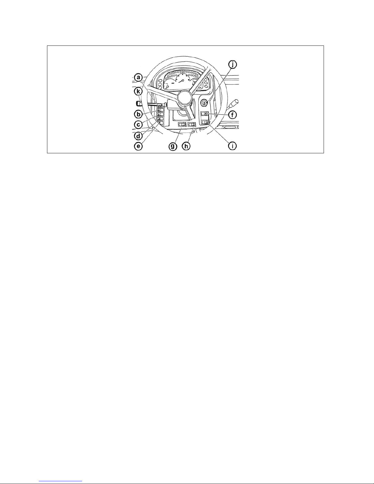
Panel of the instrument panel
a - Lights switch (off, parking, head)
b - Lo
wer beam lights in the grill of the tractor and working lights in the cabin of the tractor switch
c - Fog light switch (off - on). Fog light function is signalized by a lit symbol on the switch.
d - Working lamp switch (off - on). Working lamp function is signalized by a lit symbol on a switch.
e - Warning lights switch
f - Front drive axle button. Engaged front drive axle is signalized by lit symbol on a switch.
g - Beacon switch (off - on)
h - Working lights in the grill of the bonnet switch (off - on)
i - Differential lock button
j
- Switch box
k - Di
rection lights, lower beam head lights, head lights and horn switches acoustic and light
GETTING TO KNOW THE TRACTOR
42

Lights switch
Switch of warning lights
Lights
switch between the grill and the cabin
a - illumination off
b - side and end point lights on, illumination of licence
label, illuminated
c - all devices on in 'b' position. Lower beam head lights or
head beam lights are engaged (according to the position
of direction lights, lights and horn switches).
F56
a - warning lights on
b - wa
rning lights off
Function of warning lights is signalized by interrupted
blinking control on the dashboard.
F58
a - roof lights on
b - ro
of lights off
The switch controls the illumination in the grill or in the
roof of the cabin of the tractor. Use the lights in the roof of
the cabin only when tools covering headlights in the grill is
attached in front three-point hitch. A lit symbol on the
switch signalizes light on in the roof.
Headlights can be lit only in the grill of the bonnet.
F59
GETTING TO KNOW THE TRACTOR
43

Direction lights, lower beam head lights, head lights and horn switches
Front wheel drive switch
Push b
utton of rear, front differential locks
a - Acoustic horn - press the switch in the direction of an
axis
b - Lower beam head lights
c - Direction lights to the right
d - Direction lights to the left
e - Acoustic horn
f - Lower beam headlights
X139
Use the front driving axle for increasing the
pulling force of the tractor when rear wheels slip.
a - Front driving axle disengaged
b - Fr
ont driving axle engaged
Front driving axle is engaged at stopped tractor (braked
tractor; stopped engine, switch key is switched-of).
In the basic position, the front driving axle is engaged
(indicator lamp is 'ON') and disengaging of the axle is
made with the switch (indicator lamp is 'OFF').
C156
a - Differential lock disengaged
b - Di
fferential lock engaged
The differential lock is engaged by pressing the differential
lock push button that returns into the previous position
after loosing.
Illuminating of the symbol on the switch indicates that the
differential lock is engaged.
The differential lock is automatically disengaged after
pressing the brake pedals.
At tractors equipped with front driving axle equipped with
engageable differential lock, this is engaged
simultaneously with the rear differential lock engaging.
C157
GETTING TO KNOW THE TRACTOR
44

Switch box
Switch box key in the position (0)
Switch
box key in the position (I)
Switch box key in the position (II)
Switchbox is placed on the dashboard, see arrow.
F13BN004
The voltage of all the equipment controlled via the key is
discon
nected. The key can be removed.
S43
The voltage is connected to all the equipment excluding
starte
r. The key is in this position with the engine running.
S44
Starter and supply of all equipment is connected in this
position apart from wipers, washer, cab ventilator and air
condition. After starting, the key automatically returns back
to 'I' position.
S45
GETTING TO KNOW THE TRACTOR
45

Manual throttle
Pedals
and levers
Gear shifting lever
Gear shifting scheme
A - Maximum speed of the engine
B - Idle run
The lever allows setting of speed of the engine within
range A to B.
F13BN005
1. Travel clutch pedal
2. Foo
t operated service brake pedals connected by latch
3. Foot throttle pedal
F13BN008
- Main shifting lever
E147
Reverse can be shifted only using the reversing lever. The
scheme
is attached in the left lower corner of the
windscreen.
G148
GETTING TO KNOW THE TRACTOR
46

Reversing lever
Road and reduced speeds shifting lever
Torque
multiplier
Switching on output shaft drive
Shifting is carried out with tractor in standstill.
F
- Forward drive; lever in forward
positi
on
R
-
Backward drive; lever in
backward position
E149B
Shifting is carried out with tractor in standstill.
H
Road gears
N
Neutral
L
Reduced gears
G150
The multiplier is controlled electro
-
hydraulically using the
pushbuttons located on the shifting lever.
Activa
tion (pushbutton L) is indicated by illumination of the
indicator on the dashboard.
E151
This drive can be switched on using switches on the right
column
of the cabin.
P+11NH127b
GETTING TO KNOW THE TRACTOR
47

Lever of shifting of speed 540 (or 540E) and 1,000 rpm of the rear output shaft
PTO selection control lever
Lever
of hand brake and hitch for single-axle trailer
Shifting can be carried out when the tractor is in standstill
by pulling up or pushing down the lever.
* The tractor can be equipped optionally by 6-, 8- or 21groove termination of the output shaft.
Shifting of 540 and 1,000 (or 540E) min-1 is
possible regardless to the number of grooves on the
installed termination. Speed of the output shaft and
type o
f the termination shall be chosen depending on
the prescribed speed of the aggregated machine.
a -
1,000 min
-1
(or 54
0E min-1)
b
-
540 min
-
1
G153a
Shifting is made when the tractor stops.
a
-
Independent speed of PTO shaft - PTO shaft speed depends
upon the engine speed
n
-
Neutral
b
-
Ground speed of PTO shaft (through gearbox) - PTO
shaft
speed depends upon the engaged gear speed
G154
1. Hand brake lever.
2. Lev
er of the single-axle trailer hitch control.
When stopping or leaving the tractor you must
always secure the tractor with the parking brake.
If the tractor is standing on a slope, its wheel must be
additionally secured with wedges!
E155
GETTING TO KNOW THE TRACTOR
48

Battery disconnector
Fuel tank
Fuel t
ank drain plug
During long-time shutdown, repairs, failure or
crash immediately disconnect the battery by means of
the battery switch.
Battery switch is located on the left hand tractor side in
front of the cab.
A - battery connected
B - battery disconnected
E157
The fuel tank is fitted at the right-hand tractor side.
A plas
tic 124-litre tank is installed as standard.
At the customer's request a 150-litre tank may be
installed.
Do not step on the fuel tank!
E159
Plug for draining dirt and fuel off the fuel tank is in its
bottom
.
H800
GETTING TO KNOW THE TRACTOR
49

NOTES
50

Before a drive with the new tractor get to know how to shift gears and try individual positions
of the
shifting lever when the engine is stopped.
During normal operation and before you set up, make sure that the technical condition ensures safe
operation of the tractor.
Before you start the engine
Starting the engine
Before you start the engine, make sure:
1. If th
e tractor is properly braked.
2. If the main shifting lever is in neutral position.
Unless the clutch pedal is depressed, the engine cannot
be started, as the start security switch is not closed.
Note: Before starting of the engine it is advisable to
pressurise the fuel system by several strokes of the
manual feeding fuel pump.
G201
1. Put the key in ignition - '0' position.
2. Depr
ess the clutch pedal.
3. Move the gear lever to the neutral position.
P+11NG202
4. Turn the key to 'I' position. The glow plug indicator
illumin
ates.
5. Wait till the glow plug indicator goes out (the time
depends on the temperature of the liquid coolant).
If the glow plug indicator does not illuminate
but flashes, there is an error of the ignition system
(Ignition system error signals chapter). Have the error
repaired in a specialized service station.
6. When the indicator goes out, turn the key immediately
(do not wait for longer than 5 sec. at maximum) to 'II'
position (start).
7. After ignition, release the key immediately, it
automatically turns back to 'I' position. Do not extend the
starting process to more than 15 s.
P+11NG203
DRIVING
51

If engine does not start
Ignition system failure signalization
Manipu
lation with starter
Immediately after start
Return the key to position '0', wait 30 seconds and repeat
the start.
A maximum of 6 starting cycles is allowed (15 seconds
start and 30 seconds interruption is one cycle). Another
engine start is allowed after the starter cools off to
surrounding temperature.
Never help a stopping tractor with a starter.
There is a danger of starter damage.
G204
Ignition system failure is signalized by ignition control
blinki
ng.
- If ignition control is blinking with engine at standstill once
in a second, ignition in emergency mode occurs as with
low temperatures regardless of the temperature of
coolant.
- If ignition control is blinking twice in a second with engine
at standstill, ignition is not working.
- If ignition control is blinking permanently with engine
running, there is a failure of ignition regulator and ignition
has not been completed. Failure must be removed
forthwith, since there is the danger of accumulator
depletion.
G205
It is forbidden to start by short circuiting starter
clamps
! Tractor is started only from driver's seat!
With any manipulation or starter repair it is necessary
to disconnect minus battery pole and all shifting
levers including PTO shaft shifting lever must be in
neutral position!
Starter contacts are covered with a cap.
G206
After starting, set revolutions to 800 - 1,000 rpm
and le
t engine run without load for a period of app.
2 minutes.
Check greasing, charging and other functions ensuring
proper engine operation (controls must go out) in this time.
The time of engine operation without load must be
observed, in particular in winter period.
G207
DRIVING
52

Engine heating
G208
Do fur
ther heating of the engine when driving. Heating engine by lengthy idle run or abrupt
revolutions increase is harmful to the engine. If the temperature of coolant has not reached 45°C, do
not overcome engine revolutions over 2,000 rpm.
*Coolant heater
Is mounted on the right side of engine block.
output
1,000 W
voltage 220 V
C209
DRIVING
53

Starting the engine while using coolant heater
G210a
With l
ow temperatures of the surroundings, engine starting eases heating coolant. Leadin electrical
installation and its protection against dangerous contact must be done pursuant to valid regulations
1. First plug the plug to the heater.
2. Then connect heater to electrical network of the voltage of 220 V.
With regard for the lower engine wear with low temperature, the use of heater is recommended by
manufacturer. The duration of heating is dependent on the surrounding temperature (1 - 2 hours before the
expected start).
After completing the heating, disconnect the device first from electrical network and only then
disconnect the plug from the heater! Danger of injury due to electricity!
It is necessary to ensure tractor operator's instruction and regular revision of coolant heater
including feeding cable pursuant to valid legislation of the state where the tractor is operated at least
prior to each winter period.
Drive away
C211
1.
Depress the clutch pedal.
2. Shift the main shifting lever to neutral position.
3. Start the engine.
4. Set the engine speed from 800 to 850 r.p.m.
5. Select road or reduced gears.
6. Shift the reversing lever to the tractor's travel direction (to the front or reversing).
7. Engage applicable gear for tractor's start
8. Increase engine revolutions slightly.
9. Prepare manual brake for unbraking.
10. Release the clutch pedal only to the point of travel engagement and with simultaneous increase of
engine revolutions continue in smooth release of clutch pedal.
11. Unbrake manual brake completely.
12. Drive away smoothly and slowly.
A very fast drive away may cause overload of driving set, increased fuel consumption,
excessive tires wear and load damage. Drive away with 1st gear to be used only when driving with
a heavy trailer up the slope and in difficult terrain.
DRIVING
54

Diesel particle filter
The activity of diesel particle filter is signalized by a pair of controls (green and red) on the dashboard. Diesel
partic
le filter system failures with engine running are signalized by a lit red control on the dashboard and then
with an acoustic signal.
A short-term turning on of the red control without a subsequent acoustic signal does not
signal
ize a failure.
The conditions suitable for diesel particle filter regeneration are signalized by a lit green control on the
dashboard with engine running. Clogging of diesel particle filter automatically regenerates the exhaust gases
temperature with higher engine load.
When operating tractors with engines equipped with diesel particle filter, avoid long-term
operation or low engine load.
Diesel particle filter - system failures signalization
The exhaust system of a tractor is equipped with
a diesel particle filter which serves for cleaning exhaust
fumes. Solid particles (carbon particles) are collected and
burned in diesel particle filter which originate by burning
diesel.
FH12N056
Failures in diesel particle system failure are
signal
ized by a red control lighting up on the dashboard
with engine running and subsequently by an acoustic
signal.
If the
failure is not removed, it is signalized with any
following starting of the engine
The code of failure us displayed on a display (1) of the
displaying unit which is accessible after removing the right
cover of the steering console.
The failures are displayed on display (1) in a form of E:
double-figured code of failure
For example: E:36, number 36 representing the code of
failure
If failure is not signalized, operation data of diesel particle
filter system are displayed on the display.
The acoustic signal can be turned off by the button (2). If
the failure has not been removed, the acoustic signal is
active with repeated staring of the engine and can be
turned off again by the button (2).
If the key is in switchbox in 'I' position and the engine is
not started, approximately ten minutes later the diesel
particle filter system starts signalizing a failure. Switch the
key to '0' position and start the engine. The code of failure
on the display
E:32
or
E:33
.
FH12N075
DRIVING
55

Diesel particle filter failure codes
Diesel particle filter regeneration
Failure
code E
:
Operator´s activity
11, 12, 21,
22, 23
, 31,
34, 35, 37,
38, 41, 42,
51, 52, 61,
62
The tractor can be
worked
without any
limitations, after
terminating your work,
contact authorized
service and report the
code of failure.
32, 33, Switch the key to '0'
positi
on and start the
engine.
36 Regenerate diesel
partic
le filter.
During the operation of a tractor, diesel particle
filter is clogged by solid particles originating in engine run
when burning fuel. Clogged diesel particle filter
automatically regenerates the temperature of exhaust
fumes
with higher load of the engine.
When operating the tractor with low load of the engine ,
e.g. with long-term operation on idle run, there is a partial
clogging of diesel particle filter. This condition is signalized
with the engine run by a lit red control of diesel particle
filter, and followingly also by acoustic signal and on the
displa
y of displaying unit of diesel particle filter by failure
code
E:36
If this situation occurs, increase the load of engine and
continue working until red control of diesel particle filter
switches off and acoustic signal does not stop.
By increasing the engine load, the temperature of exhaust
fumes increases and the solid particles which clog diesel
particle filter burn.
The conditions suitable for diesel particle filter
regeneration are signalized by a lit green control on the
dashboard.
Depending on the temperature of exhaust fumes and the
degree of diesel particle filter clogging, regeneration can
take up to thirty minutes.
When regeneration is achieved, notification
information signalization goes out (error 36). If this
signalization does not go out, repeat this procedure. If
it still does not go out, you need to address an
authorized service.
Increased load of engine shall be work with
a tractor at higher engine revolutions (1 800 RPM) with
connected tools, power intake via PTO shaft or outer
hydraulic circuit.
FH12N076
DRIVING
56

Gear shifting
Shifting road and reduced speeds
Revers
ing lever
The tractors are equipped with a 4-speed synchronised
gearbox, torque multiplier, reversing and two-stage
reduction.
The 4-speed gearbox is operated using the main shifting
lever with pushbuttons to control of the torque multiplier.
Movement of the tractor forward and backward is selected
by the reversing lever.
E211
H - road speeds
N - ne
utral
L - reduced speeds
Shifting of gears of the main gearbox with reduced speeds
is the same as with road speeds.
Considering low speed of the tractor, change nearly
always means moving off from rest.
Shifting using the lever of road and reduced
speeds is only possible when the tractor is in
standstill.
G150
Reversing lever selects direction of movements of the
tractor (forward, backward).
F - tra
vel forward (16 speeds)
R - travel backward (16 speeds)
The reversing gearbox includes 16 reverse speeds that
are approximately the same as the forward speeds.
Therefore consider carefully when shifting a reverse gear
for the given character of your work.
Perform reverse shifting with clutch pedal
depressed and tractor in standstill.
E149B
DRIVING
57

Torque multiplier
Indication of function of the multiplier
Gear s
hifting from lower to higher gears
Gear shifting from higher to lower gears
The two-stage multiplier is standard equipment of all types
of tractors.
Selection of individual stages of the two-stage multiplier is
operated by two pushbuttons on the main shifting lever
head.
Selection is performed by pressing the respective
pushbutton without treading on pedal of the travel clutch.
Shifting individual stages of the multiplier is automatic
even with loading of the engine.
Shifting of the torque multiplier stages:
Note: When starting or stopping the engine there is
always shifted automatically the stage H.
H- increase of travel speed
L- decrease of travel speed
E216
Engagement of the multiplier (decrease of travel speed) is
indicated by a light indicator on the dashboard.
E217
Depress the clutch pedal (clutch disengaged). At the same
time release the pedal of foot fuel control and shift the
applic
able higher gear. Release the clutch pedal (clutch is
engaged) smoothly and at same time increase engine
revolutions.
Note: For increasing the life cycle of synchrones, it is
possible to shift from higher to lower gear with the
socalled double declutching.
C212
Depress the clutch pedal and shift the gear shifting lever
throug
h neutral to lower gear.
Note: For increasing the life cycle of synchrones, it is
possible to shift from higher to lower gear with the
socalled double declutching.
C213
DRIVING
58

Travelling up the slope
Travelling down the slope
Differ
ential lock
The differential can be locked by pressing a switch that returns back to its original position after it is released.
Locking of the differential is indicated by an illuminated symbol on the switch.
Depressing of the brake pedals unlocks automatically the differential.
Do not use the differential lock when driving through road bends.
Shift gears from higher to lower gears in time
when travelling up the slope so as to avoid drop of
engine revolutions under 800 rpm and do not allow
ride leading to stopping the engine for overload.
C215
Travelling down the slope without en engaged
gear i
s forbidden. If you are going down a longer
slope engage the lower gear the steeper the slope.
Engage the lower gear before the slope if possible.
Note: The gear with which you will reliably overcome
ascension, it is the one with which you will safely go down.
C216
DRIVING
59

Control of front driving axle
Driving with engaged front driving axle
Foot b
rakes
The front driving axle is engaged in the basic position.
Engagement of the front driving axle is indicated by an
illuminated symbol on the switch.
It can be disengaged using a switch on the dashboard.
a - Front driving axle engaged
b - Front driving axle disengaged
At the stopped tractor, the front driving axle is engaged at
stopped tractor (braked tractor, stopped engine, key
switch in '0' position).
In case of a drop of air pressure in the
compressed air system of the tractor the front driving
axle is engaged automatically.
C219
Use the front driving axle with slipping of the
rear w
heels to increase the traction force of the
tractor. It is permitted to engage the front driving axle
on roads and hard surfaces up to 15 km/h (travel with
engaged front driving axle causes increased wearing
of front tyres).
Permanent engagement of the front driving axle is
permitted if there is a farming mechanism attached to the
front suspension. This condition is mentioned in the
instructions manual to the respective mechanism.
Maximum permitted speed when driving with these
attachments is 15 km/h.
P11NC220
The foot brakes are disk wet type, hydraulic-controlled,
with two pedals and automatic pressure balancer.
During travel both pedal have to be coupled
with a
latch. Use uncoupled pedals for barking of the
right or left wheel only when working in terrain and on
a field at low travel speeds.
Note: When driving from a steep downslope with a trailer
or semi-trailer equipped with air or hydraulic brakes it is
necessary to start braking by foot brake already from
beginning of the slope!
With braking by one brake pedal the trailer
brakes are not activated!
C221
DRIVING
60

Air brakes of trailers and semi
-
trailers
Warning indication of air pressure drop
One-ho
se and two-hose brakes
One-hose brakes
Air brakes of trailers (semi-trailers) and brakes of the
tractor are designed so that braking effects of both
vehicles are synchronised.
In case of a drop of pressure the transfer valve
disables the secondary consumers (differential lock,
disengagement of the front driving axle).
When driving with a trailer or semi-trailer the foot
brake pedals shall be coupled and secured by a latch!
With braking by one brake pedal the trailer air brakes
are not activated.
C222
Decrease of air pressure under 450 kPa is indicated by
a red
lamp and red symbol of a tractor with a sign STOP
on the dashboard.
In case of a pressure drop in the compressed
air system under 450 kPa the tractor with braked
trailer or semi-trailer may not travel until air pressure
increases.
G226
1. clutch head of one-hose brakes
2. clu
tch heads of two-hose brakes
Clutch heads after disconnection or without
a connected trailer, articulated trailer must be closed
by a valve.
P11NX227
Valve is marked with a black colour.
Operating pressure is adjusted with the control valve at
600 ± 2
0 kPa.
When connecting the trailer (articulated trailer)
with a maximum allowed weight approved for the type
of tractor at stake is a maximum allowed speed of the
set of 30 km per hour! Maximum allowed speed of the
set is defined by maximum allowed speed of the
slower vehicle of the set.
P11NX228
DRIVING
61

Two-hose brakes
Hydraulic brakes of trailers
Connec
ting and disconnecting quick couplings of trailer hydraulic brakes
When connecting and disconnecting quick couplings, take increased care with regard for
remaining oil which remains in the socket or in the plug of quick coupling. For ecological reasons, it
is necessary to remove this remaining oil after every disconnection of quick couplings with any
textile material.
Operating pressure is adjusted with the control valve at
740 ± 20 kPa. Capacity of air tank is 20 l.
The valve of the left head is labelled in yellow (braking
branch), the valve of the right head is labelled in red (filling
branch).
When connecting the trailer (articulated trailer)
with a maximum permitted speed approved for the
type of tractor, the maximum permitted speed of set is
40 km per hour!
Maximum permitted speed of set is given by maximum
permitted speed of the slower vehicle of the set.
P11NX229
Connect hydraulic brakes of trailer or articulated
traile
r to the quick couplings marked by an arrow.
Control of hydraulic brakes of trailers (articulated trailers)
and control of tractor brakes is done so that the braking
effect of both vehicles is synchronized. Working pressure
is derived by oil supplied by non-switched on/switched off
gear pump of hydraulics. Brake valve of the trailer is done
by the pressure of brake fluid from main braking rollers
depending on the force effecting on the brake pedal. The
pressure on clutch head must be 12 - 15 MPa with
maximum depression of brake pedal. Brake valve of trailer
prefers the function of brakes to the function of hydraulics.
If there are shocks when foot brake pedals are depressed
in the pipeline of hydraulic circuit, it is necessary to bleed
the hose from the brake valve to the quick coupling.
When driving with connected trailer or
articulated trailer, the pedals of foot brake must be
connected and secured by a valve! When braking with
one brake pedal, hydraulic brakes of the trailer are not
active.
P11NE231
DRIVING
62

Stopping the tractor
-
manual brake
Stopping the engine
Leavin
g the tractor
Under normal conditions stop the tractor slowly. Shortly
before stopping:
1. Tread on the clutch pedal and brake the tractor by the
foot brake.
2. Move the main shifting lever to neutral position.
3. With each stop secure the tractor using the hand brake
against spontaneous moving off. Application of the hand
brake is indicated by a light on the dashboard.
G232
After operation of the tractor when the engine was fully
loaded
the engine must be cooled.
1. When the engine is started, leave it idling without load
for ca. 5 minutes.
2. Move the manual regulation lever to the idling position.
3. When the key is turned from 'I' position to '0' position,
the engine is stopped.
Before you leave the tractor with safety cabin, do not
forget
remove the key in position '0' from the ignition box
(in positions I and II the key cannot be pulled out).
The tractor shall be secured against
spontaneous moving off:
1. Engine switched off.
2. 1st gear engaged.
3. Hand brake applied.
In case that the tractor is standing on a slope, its
wheels shall be wedged.
Lock the cabin.
Note: When the engine is stopped, the front driving axle is
engaged automatically.
C230
DRIVING
63

Warning signalization of hydrostatic steering failure
Import
ant warnings
Hydrostatic steering pump failure is with oil pressure drop
under 120 kPa behind a pump signalized on a dashboard
by an applicable symbol.
Note: When starting the tractor or with low engine
revolutions, the control may blink, if it switches off after
starting or increasing the revolutions, it is not a failure.
F_02_68
In case that indicator of lubrication, battery recharge or
a faul
t of the hydrostatic steering is on during normal
operation of the tractor, stop the tractor immediately, stop
the engine and contact a specialised repair shop. This
prevents a serious damage or breakdown of the tractor.
G238a
DRIVING
64

General principles of new tractor run
-
in in first 100 hours of operation
G251
During first 100 hours of operation:
l Load tractor in a normal way, avoid operation with low or maximum engine revolutions
l Avoid operation under partial loading of the engine
l Avoid excessive idle run operation
l Check oil levels in engine often (during this time increased oil consumption is normal)
l Check screw joints in particular in supporting parts of tractor
l Learned insufficiencies to be removed immediately, you will thus prevent subsequent damage or
endangered operation
l Keep the same procedure also after tractor complete overhaul
In first 10 hours of operation
From 100 hours of operation
l perform run-in in traffic
l tighten fastening nuts of front and rear wheels
including connectionbead / rim with prescribed
torque
G252
After drive in completion you can work with tractor without
limitations.
Recommended
operation
revolutions
1,400 - 2,300
rpm
Idle run revolutions 800 ± 25 rpm
Operation oil
pressure
0.2 - 0.5 MPa
Oil pressure with
idle run revolutions
min. 0.05 MPa
Max. coolant
temperature
106°C
E256
RUNNING-IN THE TRACTOR
65

NOTES
66

Work with PTO shaft
Before attaching of an implement, driven by means of the tractor PTO shaft, check the speed
compatibility of both, it means tractor PTO shaft and implement driven shaft (540 rpm or 1,000 rpm).
Different PTO speed values may cause serious damages and injuries.
1. When working with the output shaft pay attention to proper fixing of all covers.
2. After completion of work install always the output shaft cover.
3. Connect and disconnect the articulated shaft of the coupled mechanism to the rear output shaft of
the tractor always when the engine is stopped, output shaft disengaged and lever of shifting of
dependent and independent rpm of the output shaft in position 'N' - neutral!
4. Connect and disconnect the articulated shaft of the coupled mechanism to the front output shaft
of the tractor always when the engine is stopped and output shaft disengaged!
5. Perform any repairs or cleaning of parts of the coupled mechanisms driven by the output shaft
only when the engine is stopped, output shaft disengaged and lever of shifting of dependent and
independent rpm of the output shaft in position 'N' - neutral.
Front and rear PTO shaft control
P+13N010
Engagement (with minimum engine revolutions of 1,500 min-1) and disengagement of PTO shafts is done by
switches:
(A) standard tractor - placed on the right pillar of the cab.
(B) tractor equipped with electrohydraulics EHR - placed on the external hydraulic circuit control panel
The switches are equipped with mechanical catches (3) against undesired switch. When switching the
switch, press the catch (3) in the direction of the arrow.
Both PTO shafts are set in motion (front and rear) by switching both switches. The engagement of PTO
shafts is signalized by a lit symbol on the switch.
Rear output shaft - shifting of dependent and independent speed of the shaft
(1)
The switch controls the rear PTO shaft
(2)
The switch controls the front PTO shaft
Shifting is performed by the lever (1) when the tractor is in
standstill.
a - Independent speed of the output shaft (rpm of the
shaft depends on rpm of the engine).
n - Neutral position. Use this position to facilitate
connection of the farming mechanism propeller shaft.
The terminal of the rear output shaft is freel
y
rotable.
b - Depende nt speed of the output shaft (rpm and
direction of rotation depends on the engaged gear and
position of reversin
g
lever).
G154
DRIVE OF FARMING MACHINES
67

Rear output shaft - shifting of speed of the output shaft 540 and 1,000 or 540E rpm
Replaceable end points of rear PTO shaft
Facilitating connection of joint shaft of an aggregated machine to the tractor
FH12N002
For facilitating the connection of joint shaft of aggregated machine to a tractor a button (1) placed on
mudguards can be used.
With the engine running and rear PTO shaft switch off, spinning of rear PTO shaft occurs after pressing th e
button (1). PTO shaft stops spinning after releasing the button.
Beware: Rear PTO shaft revolutions preselection lever must not be in (N) position or in the position of
a dependent revolution of rear PTO shaft.
When manipulating with PTO shaft by means of buttons (1), the operator must stand beyond
the space of the connected tools not to be caught or injured.
Shifting is performed by the lever (1) when the tractor is in
standstill.
The tractor is equipped standardly with a combination of
540 and 1,000 rpm of the output shaft; other optional
combination is 540 and 540E rpm of the output shaft.
Shifting of 540 and 1,000 (or 540E) min
-1
is
p
ossible regardless to the number of splines of the
installed terminal. Speed of the output shaft and type
of terminal shall be chosen depending on the
p
rescribed rpm of the coupled mechanism.
a -
1,000 min-1 or 540E min
-1
b -
540 min
-1
G153
The tractor is equipped with six or twenty-one splined
replaceable end point of rear PTO shaft.
Replacement procedure:
1. Use safety ring pliers to demount a safety ring (1)
2. Remove replaceable end point by pulling in the
direction of an arrow (2)
3. Mount the end point in an opposite way, pay increased
attention to the mounting of the safety ring (1)
Replacement of the terminal shall be performed
when the engine is stopped.
Rpm of the output shaft and terminal type shall be
chosen depending on the prescribed rpm of the
coupled mechanism.
Shifting 540 and 1,000 or 540E min
-1
is possible
regardless to the number of splines of the installed
terminal.
E357
DRIVE OF FARMING MACHINES
68

Front PTO shaft
Maximum transferred output
P15N038
Front PTO shaft is equipped with a solid six or twenty-one
splined end point and it comes only in design of 1,000
revolutions.
Tractor may be equipped with front PTO shaft with varied
direction of spinning:
a - In compliance with the direction of engine
revolutions (standard)
b - Against the dire ction of engine revolutions
(*on request)
F_02_64
Drive of machines with greater inertia masses
(crushers, rotary harrows, reaping machines, etc.)
Output shaft Transferred power
front
1,000 min
-1
60 kW*
rear
1,000 min
-1
full engine power
540 min
-1
full engine power
540E min
-1
full engine power
Cardan shaft for drive of these machines must be
equipped with the so called freewheel clutch which
ensures disconnection of torque transfer with retroaction
from the machine on the tractor.
troj
DRIVE OF FARMING MACHINES
69

NOTES
70

Before a drive make sure that the technical condition ensures safe operation of the tractor.
In case that a trailer or implement is coupled, verify its coupling and proper fixing of the load.
Never get out of the tractor to couple a trailer yourself. Pay also attention to your assistant.
Front hook
Multistage adjustable suspension
Height adjustment and disassembly of the CBM stage hitch
Used only for towing tractor without connected trailer or
a different connected machinery.
Use a drawbar or a cable for releasing tractor.
Never use chains! The possibility of fatal injury if
a chain pulls apart!
It is forbidden to use tractor axles (individual
travelling wheels) such as reeling jack when rescuing
a sunken tractor.
NM13N023
Serves for connecting double axle or lighter single
-
axle
trailers. Guidance nozzle is vertically adjustable. When
working with various agricultural machines it is necessary
to adjust the suspension vertically or demount where
necessary.
E302
By moving the control lever in the arrow direction to
position (1) you will release the lever and by moving it
subsequently to position (2) you will retract the locking
pins (3). Now, the stage hitch is released and you can
adjust its height or disassemble it. When you release the
lever from position (2), the locking pins (3) will extend and
the lever will automatically return to the initial position.
D202
TRANSPORT USE
71

Automatic mouth of the CBM stage hitch
Modular system of hitches for trailers and semi-trailers
Swinging draw-bar console module
Swinging draw-bar console with a fixed pin module
When the lever (1) is moved in the direction of the arrow
(a), the pin (2) is retracted to the upper position, which is
signalled by the extended indicator (3), see fig. (A). When
the mouth gets onto the shaft lug, the pin will automatically
slide into the lug of the connected trailer. You can lower
the hitch pin (2) manually by moving the lever (1) in the
arrow (b) direction. The insertion of the pin is signalled by
the retracted indicator (3), see fig. (B).
After the attachment of the trailer you must
always check whether the indicator (3) is retracted in
accordance with fig. (B).
E304
Module types:
Fig. (B) - Swinging draw -bar console
Fig. (C) - Swinging draw-bar console with a fixed pin
Fig. (D) - Console with a ø 80 ball
Disassembly, fig. (A):
1 - Remove the locking screw (1).
2 - Secure the module against sinking, release and
disassemble the pins (2).
3 - Slide the module out of the console downwards.
Do the assembly in the reverse order.
D204
The swinging draw
-
bar console module is located in the
stage hitch console.
Swinging draw-bar
Disassembly:
1 - Release and remove the pins (1).
2 - Slide the swinging draw-bar out in the arrow direction.
Do the assembly in the reverse order.
D205
Perform the assembly and disassembly of the swinging
draw-bar in accordance with the 'Swinging draw-bar'
chapter.
Connecting the shaft lug to the fixed pin (3):
1 - Release and remove the pin (1).
2 - Lift the locking wedge (2) in the arrow direction.
3 - Connect the shaft lug to the fixed pin (3):
4 - Return the locking wedge (2) to the original position
and secure it with the pin (1).
D206
TRANSPORT USE
72

Console with a ø 80 ball module
Towing bar
Hitch for a single-axle CBM semi-trailer
Coupling of a single-axle trailer
The console with a ø 80 ball is only used to
connect semi -trailers with a hitching device designed
for a ø 80 ball.
Releasing the hitch, fig. (A):
By moving the lever (1) in the arrow direction you will
remove the locking wedge (2).
Locking the hitch, fig. (B):
By moving the lever (1) in the arrow direction you will
retract the locking wedge (2).
D207
Height of the towing bar can be adjusted within entire
extent of the adjustable height.
Only those farming mechanisms can be attached to the
towing bar that load it permanently downwards.
When working with the towing bar dismount the
multi-level hitch and pivoted pull bar.
E312
The hitch for a single
-
axle trailer can be equipped with
a hook (A) that is designed for coupling of single -axle
trailers having poles according to the standard ISO 5692
(inner diameter of the eye 50 mm and height of the eye 30
mm) or pivoted pull bar (B).
The coupling hook is lowered and lifted hydraulically using
length-adjustable telescopic pull rods.
Replacement of the hook for the pivoted pull bar (C):
1. Lower the hitch.
2. Unlock and remove the pin (1).
3. Remove the hook in direction of the arrow.
The pivoted pull bar is mounted in reverse order.
D208
Coupling can be performed using the hydraulic circuit
lever (2). The hitch hook with the trailer pole eye is lifted
hydraulically to the position where the supporting hooks
click under pins of the hitch carrier.
The lifting arms of the hydraulic device then shall be
lowered to lock the supporting hooks onto the carrier pins;
the telescopic pull rods shall not be under any tension.
P+11N003
TRANSPORT USE
73

Uncoupling of a single
-
axle trailer
Hook of the mounting for a single-axle trailer
Coupling with a trailer or semi -trailer
This can be performed after slight lifting of the hitch by the
inner hydraulic circuit lever.
Move the control lever backwards.
The lever is located on the left side of the driver's seat.
Lower the hitch using the inner hydraulic circuit lever and
disconnect the trailer pole eye.
E311
The hook of the mounting for a single
-
axle trailer is
located in the bracket on the left -hand side of the cabin
back wall.
G313
The tractor can be coupled only with a tractor trailer after
matching of operating brakes of the tractor and pneumatic
or hydraulic brakes of the trailer.
In case of coupling with a semi-trailer the static loading of
the rear axle of the tractor may not exceed the maximum
permitted value.
G900a
TRANSPORT USE
74
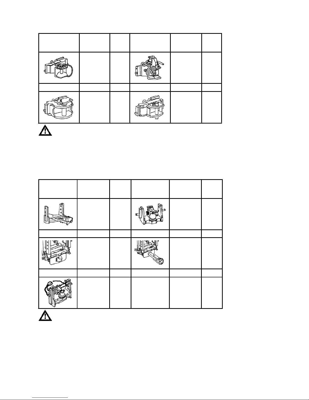
Maximum permissible vertical static load of hitches for trailers and semi
-
trailers
The maximum weight of an aggregated braked trailer or semi-trailer must not exceed the value
specified on the data plate of the tractor and the value specified in the technical certificate of the
tractor. The maximum permissible speed of the set results from the maximum permissible speed of
the slower vehicle in the set.
Hitch of class C: max. weight of the trailer 6,000kg.
Hitch of class D2: max. weight of the trailer 14,000kg.
Hitch of class D3: max. weight of the trailer 20,000kg.
Hitch type Permissible
vertical static
load
Hitch
pin Ø
Hitch type Permissible
vertical static
load
Hitch
pin Ø
2 000 kg
31 mm
2 000 kg
38 mm
Hitch class D2 Hitch class C
2 000 kg
43 mm
2 000 kg
28 mm
The maximum weight of an aggregated braked trailer or semi-trailer must not exceed the value
specified on the data plate of the tractor and the value specified in the technical certificate of the
traktor. The maximum permissible speed of the set results from the maximum permissible speed of
the slower vehicle in the set.
Hitch type Permissible
vertical static
load
Hitch pin
(ball) Ø
Hitch type Permissible
vertical static
load
Hitch
pin
(ball) Ø
736 kg
31 mm
2 000 kg
80 mm
3 000 kg
47 mm
1 200 kg
31 mm
Fixed pin
2,000 kg
44,5 mm
TRANSPORT USE
75

NOTES
76

Hydraulic system
Hydraulics control panel
P+13N002
As a standard, the tractor is equipped with a rear three-point hitch control with mechanical regulation (A),
hereinafter referred to as mechanical hydraulics (the description of functions in a separate chapter).
Upon customer´s wish, the tractor may be equipped with a rear three-point hitch control with electronic
regulation, hereinafter referred to as electrohydraulics EHR (the description of functions in a separate
chapter).
1. Rear three-point hitch control (internal hydraulic circuit)
2. External hydraulic circuit control
It consists of the inner and outer circuits. Gear pump is the
source of pressure oil.
Oil is taken from reservoir shared by gearbox and
transmission.
Hydraulic pump cannot be switched off. If the engine is
working, the pump is on.
The amount supplied is:
standard 50 l/min
on request 60 l/min
The pressure in hydraulic system raised by the hydraulic
pump is restricted by a safety valve to 19 MPa.
P11N001
HYDRAULIC SYSTEM
77
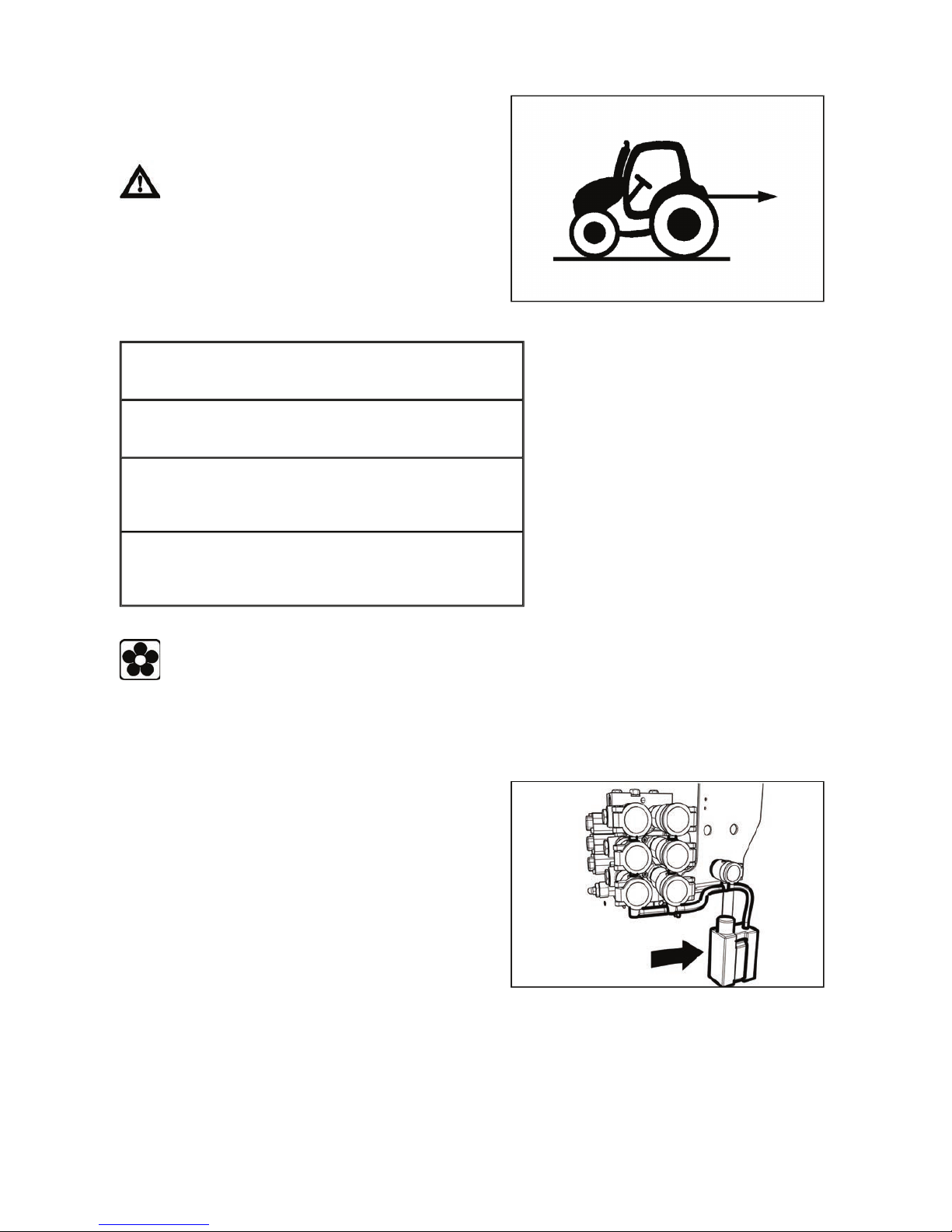
Amount of oil taken from outer hydraulic drives
If the amount of oil in transmission decreases after
disconnecting the tool due to its permanent outflow out of
the tractor into the machine's hydraulic circuit, refill the oil
missing.
If the amount taken exceeds the limit, hydraulic
p
ump can absorb air and can get damaged.
For maximum amount of oil taken see the following table.
E413
Connecting and disconnecting quick-couplers
When connecting and disconnecting the quick-couplers pa
y
increased attention with regard to
the residual oil that remains in the socket or on the plug of the quick-coupler. For environmental
reasons after every disconnection of quick-couplers this residual oil must be removed with any
textile material.
Quick-couplings with drip collection
Working area: in flat terrain
Max. amount of oil taken: 20 liters
Gearbox filling: standard filling
Working area: in a slope
Max. amount of oil taken: 13 liters
Gearbox filling: standard filling
Working area: in flat terrain
Max. amount of oil taken: 27 liters
Gearbox filling: gearbox oil filling increased by 7 liters(max.
amount of oil in gearbox allowed)
Working area: in a slope
Max. amount of oil taken: 20 liters
Gearbox filling: gearbox oil filling increased by 7 liters(max.
amount of oil in gearbox allowed)
On request, dripping system for holding leakage oil can be
installed. Regularly check whether the tank is not full;
dispose of the oil in an environment-friendly way.
P+11N020
HYDRAULIC SYSTEM
78

Connecting machines and tools to External hydraulic circuit
Connecting a double acting cylinder
A double acting cylinder must always be connected to quick couplers of one section.
Connecting machinery and tools assembled from more parts
When working with agriculture machinery which is assembled from more parts (combinators, scrubbers, or
harrows) where the edge frame is hinged to the central frame because it is diagonally folded during transport
by independent hydraulic cylinders which are controlled by outer hydraulic circuit of the tractor, it is
recommended to connect the lifting arms of the cylinders to quick couplers (3) and (5) which are equipped
with a one-way valve.
Connecting rotary hydraulic engine
If a hydraulic engine is connected to outer hydraulic drive, it is always necessary to connect its returnable
arm to quick coupler (0). Filling (pressure) arm can be connected to quick couplers (1) or (2), where the
hydraulic engine is protected by the 'kick-out' function from overload. This function stops the hydraulic engin e
if pressure in the filling arm exceeds 17 MPa.
Connecting reverse rotary hydraulic engine
Due to its function, reverse rotary hydraulic engine must be connected to quick couplers of one section. It is
recommended to use quick couplers (1) and (2), where the hydraulic engine is protected by the 'kick-out'
function from overload. This function stops the hydraulic engine if pressure in the filling arm exceeds 17
MPa. If the hydraulic engine is connected to quick couplers of different sections, both arms must be
equipped with safety valves which can be relied on to restrict high pressure peaks during run-out. Connect
the safety valves drain to quick coupler (0).
Connecting external hydraulic distributor
It is recommend to connect external hydraulic distri bu tor to quick couplers (4) or (6). Control levers (b) and
(c) are mechanically locked in these positions without hydraulic lock.
Auxiliary machines using oil filling of external hydraulic circuit must be filled with the same
kind of oil, which is recommended for gear system of the tractor! Quick-couplers sockets of an
auxiliary machine need to be properly cleaned before connecting.
Front outlets of the external hydraulic circuit
On request, the tractor can be equipped with external
hydraulic circuit outlets located in the front.
The quick couplings (1) and (2) are the pressure
couplings, the quick coupling (0) is directly connected to
the space of the axle final drive housing and is designed
so that the return oil can flow back from the external
hydraulic appliances.
The quick couplings sockets with the 12.5 mm inside
diameter comply with the international ISO
recommendations.
P13N002
HYDRAULIC SYSTEM
79

Control of the external hydraulic circuit front outlets
The front outlets of the external hydraulic circuit are
controlled by a lever (a) which has four positions:
N - Neutral position. Quick coupler drives (1) and (2) are
closed and oil in the hydraulic appliance connected is
blocked. Lever
(a)
is locked in this position.
1 - Pressure in quick co upler (1). Quick coupler (2) is
connected with the drain. Lever (a) is locked in this
position. In case pressure exceeds 16.5 MPa when
connected to quick coupler (1), lever (a) automatically
returns to
(N)
position - 'kick-out' function.
2 - Pressure in quick co upler (2). Quick coupler (1) is
connected with the drain. Lever (a) is locked in this
position. In case pressure exceeds 16.5 MPa when
connected to quick coupler (2), lever (a) automatically
returns to
(N)
position - 'kick-out' function.
P - Floating position. Both quick couplers (1) and (2) are
connected with the drain and oil is free to flow in both
directions. Lever
(a)
is locked in this position.
P13N001
HYDRAULIC SYSTEM
80

The hydraulic system is intended for lifting and lowering of agricultural machines and implements attached in
the rear three point hitch.
Hydraulics control panel
Ways to regulate inner hydraulic circuit
P+11N002
Hydraulic system allows of three ways to regulate the lifting of the rear three-point hitch:
Position regulation (img. 1) - the tool connected to the rear three-point hitch is automatically kept in the same
height (position) with regard to the tractor.
Mixed regulation (img. 2) - a combination of position and power regulation. Suitable mainly for tilling areas of
different soil resistance.
Power regulation (img. 3) - the tool connected to the three-point hitch is automatically being adjusted
depending on changing soil resistance.
All the regulations can also be used when working with a tool equipped with a support wheel in so-called fre e
(floating) position.
Controlling the inner hydraulic circuit
Hydraulics control panel is located in the area of the right
wing.
Controlling the rear three-point hitch is enabled by the
inner hydraulic circuit (1).
Controlling outer hydraulic circuits (couplers) is enabled by
outer hydraulic circuit (2).
P+11N001
1. position or power regulation lever
2. lever for selecting floating position, adjusting the
height of the three-point hitch in position regulation
or mixed regulation.
3. three-point hitch lowering speed control
4. hydraulic system sensitivity control
5. adjustable stop
P+11N003
MECHANICAL HYDRAULICS
81

Free (floating) position
Adjustable stop
Three-point hitch lowering speed control
Free (floating) position makes it possible to work with tools
with a support wheel. In this position, the arms of the rear
three-point hitch are loose.
Move lever (2) to the front position (a).
The position of lever (1) makes no difference.
P+11N004
Under default settings, it is recommended to set the
adjustable stop (1) to a position on the edge between
floating position and the beginning of the range of lifting of
the rear three-point hitch (b). After pushing the lever
towards you, the lever can be moved over the adjustable
stop.
P+11N009
Three-point hitch lowering speed control (3) selects the
speed of lowering the arms of the rear three-point hitch.
Turning the knob in (b) direction reduces the lowering
speed of the arms of the rear three-point hitch, turning it in
(a) direction increases the speed. If the knob is turned in
(b) direction to its stop point, the arms of the rear threepoint hitch cannot be lowered.
P+11N006
MECHANICAL HYDRAULICS
82

Hydraulic system sensitivity control
Position regulation of the lifting of the rear three-point hitch
P+11N008
Position regulation of the lifting of the rear three-point hitch means that the tool connecte d to the rear threepoint hitch is automatically kept in the same height (position) with regard to the tractor.
Move lever (1) to the front position (d). Adjust the height of the rear three-point hitch with tools within the (b)
range by lever (2). Adjusting the height is smooth within the range 1 - 9. In position 1, the arms of the rear
three-point hitch are in the lower position, in position 9, in the highest position. Position (c) is a transport
position when the tools connected to the rear three-point hitch is raised at maximum.
To transport tools which are connected to the rear three-point hitch always use position
regulation.
To raise tools into transport position, turn the three-point hitch lowering speed control knob (3) in
the direction shown by the arrow up to the stop point, which results in int errupting the oil flow in
hydraulics. Should tools connected to the rear three-point hitch not be lowered, check the position of
the speed lowering control knob (3) - turn it in the opposite direction than shown by the arrow.
If tools connected to the rear three-point hitch are long and heavy, the arms of the rear three-point
hitch may get locked in the transport position during transport. If the lowering speed control knob (3)
is loosened and the tools still cannot be lowered, move lever
(2)
to the floating position (c) for a short
time and immediately get back to the lowering range (d). The arms of the rear three-point hitch start
to go down as set by lever (2).
Hydraulic system sensitivity control (4) adjusts the
sensitivity of the hydraulics in power or mixed regulation.
Turning the knob in (a) direction increases sensitivity,
turning it in (b) direction decreases sensitivity.
E408
MECHANICAL HYDRAULICS
83

Power regulation of the lifting of the rear three-point hitch
P+11N010
Power regulation of the lifting of the rear three-point hitch means that the tool connected to the rear threepoint hitch is automatically being adjusted depending on changing soil resistance.
Set the adjustable stop (5) to a position on the edge between floating position and the beginning of the range
of lifting of the rear three-point hitch.
Move lever (2) to (f) position - to the adjustable stop (5).
Move lever (1) to (g) position, accelerate the tractor and move lever (1) in the direction shown by the arrow to
set the depth of tilling (in (g) position, depth is the lowest).
Once the depth of tilling is set, lever (1) must be kept in constant position. At the end of each row, raise the
tool connected to the rear three-point hitch only by moving lever (2) to (e) position. To lower the tool to its
operating position again, move lever (2) to (f) position.
The rear three-point hitch ma
y
start oscillating under the influence of changing soil resistance.
To reduce oscillation, set lower hydraulic system sensitivity by turning the contro l knob (4) in (b)
direction.
Mixed regulation of lifting the rear three-point hitch
P+11N010
Mixed regulation of lifting the rear three-point hitch means that the tool connected to the rear three-point hitch
is automatically being adjusted depending on changing soil resistance and at the same time it prevents any
increase in depth of tilling in case of smaller soil resistance.
Set the depth of tilling by lever (1) as described in 'Power regulation of the lifting of the rear three-point hitch'.
Then start moving lever (2) in the direction shown by the arrow until the arms of the rear three-point hitch
start to rise slightly. Herewith, mixed regulation has been set. Move the adjustable stop (5) to l ever (2) which
has been set and lock it. At the end of each row, raise the tool connected to the rear three-point hitch on ly by
moving lever (2) to (e) position. To lower the tool to its operating position again, move lever (2) to the preset
stop.
MECHANICAL HYDRAULICS
84

Exterior rear hydraulic arms controls
Outer hydraulic circu i t
Exterior rear hydraulic arms controls are located on the
rear right wing. They make it easier for the operator to
conncet tools by controlling the movements of the lower
drawbars of the three-point hitch from the outside. They
only serve for connceting and disconnecting the tools.
Img. (A)
Before using exterior controls, move the power regulation
lever (1) to its utmost position.
Lowering hydraulic arms img. (B):
Move lever (3) in the direction shown by the arrows
(moving the lever is restricted with a link). By repeating
this procedure, hydraulic arms are lowered in small steps.
Raising hydraulic arms img. (C):
Move lever (3) in the direction shown by the arrows
(moving the lever is restricted with a link). By repeating
this procedure, hydraulic arms are raised in small steps.
If the lifting device controlled by exterior
controls is loaded, movement of the lower drawbars
within one step (on the exterior controls) is longer
than if unloaded.
P+11N016
It supplies pressure oil for hydraulic devices on outer
drives of hydraulics ended with couplers. Coupler sockets
with 12.5 mm bore are in accordance with the international
recommendation of ISO.
P+11N012
MECHANICAL HYDRAULICS
85

Outer hydraulic circui t controls
P+11N015
Outer hydraulic circuit controls are located on the right wing.
lever (a) controls the lower section of distributor - quick couplers (1) and (2)
lever (b) controls the central section of distributor - quick couplers (3) and (4)
lever (c) controls the upper section of distributor - quick couplers (5) and (6)
Quick coupler (0) is directly connected with transmission and it is supposed for recuperative oil of exterior
hydraulic appliances (e.g. from rotary hydraulic engines etc.).
A
ccording to the equipment of the tractor, the following combinations of control levers and quick couplers can
be supplied:
lever (a) - quick couplers (1) and (2)
levers (a) and (b) - quick couplers (1), (2), (3) and (4)
levers (a),(b) and (c) - quick couplers (1), (2), (3), (4), (5) and (6)
Quick coupler (0) is supplied in any case.
If the tractor is equipped with front three-point hitch, use lever (b) to control it. When the front
three-point hitch is used, quick couplers cannot be connected as they are pressured together with
the front three-point hitch! When you finish using the front three-point hitch and want to use the
section with quick couplers 3 and 4 with connection to the front three-point hitch, raise the arms of
the front three-point hitch to the transport position and move the front three-point hitch lever to the
'locked' position.
Locking control levers
Outer hydraulic circuit control levers are locked in neutral
(N) position.
To unlock them, raise the lock control (1) and turn it to
a stop point in the direction shown by the arrow.
To lock them again, move the levers to neutral (N) position
and turn the lock control in the opposite direction than
shown by the arrow to a stop point and push the control
down. This locks the lever in neutral position.
For safety reasons, always lock outer hydraulic
circuit levers in neutral position (N).
P+11N014
MECHANICAL HYDRAULICS
86

Different functions of outer hydraulic circuit control levers
P+11N017
There are four positions of the lever (a):
P+11N018
There are four positions of the lever (b):
N - Neutral position. Quick coupler drives (1) and (2) are closed and oil in the hydraulic appliance connected
is blocked. Lever
(a)
is locked in this position.
1 - Pressure in quick coupler (1). Quick coupler (2) is connected with the drain. Lever (a) is locked in this
position. In case pressure exceeds 16.5 MPa when connected to quick coupler (1), lever (a)
automatically returns to (N) position - kick-out function.
2 - Pressure in quick coupler (2). Quick coupler (1) is connected with the drain. Lever (a) is locked in this
position. In case pressure exceeds 16.5 MPa when connected to quick coupler (2), lever (a)
automaticall
y
returns to (N) position - kick-out function.
P - Floating position. Both quick couplers (1) and (2) are connected with the drain and oil is free to flow in
both directions. Lever
(a)
is locked in this position.
N - Neutral position. Quick coupler drives (3) and (4) are closed and oil in the hydraulic appliance connected
is blocked. Lever
(b)
is locked in this position.
3 - Pressure in quick coupler (3). Quick coupler (4) is connected with the drain. It is necessary to hold lever
(b) in this position, when released, lever (b) automatically returns to (N) position. In addition, quick
coupler (3) is equipped with a one-way valve - convenient for connecting a tool which requires higher
degree of impermeability - minimum lowering of the tool during transport.
4 - Pressure in quick coupler (4). Quick coupler (3) is connected with the drain. Lever (b) is locked in this
position.
P - Floating position. Both quick couplers (3) and (4) are connected with the drain and oil is free to flow in
both directions. Lever
(b)
is locked in this position.
MECHANICAL HYDRAULICS
87

P+11n019
There are four positions of the lever (c) which controls quick couplers (5) and (6):
N - Neutral position. Quick coupler drives (5) and (6) are closed and oil in the hydraulic appliance connected
is blocked. Lever
(c)
is locked in this position.
5 - Pressure in quick coupler (5). Quick coupler (6) is connected with the drain. It is necessary to hold lever
(c) in this position, when released, lever (c) automatically returns to (N) position. In addition, quick
coupler (5) is equipped with a one-way valve - convenient for connecting a tool which requires higher
de
g
ree of impermeability - minimum lowering of the tool during transport.
6 - Pressure in quick coupler (6). Quick coupler (5) is connected with the drain. Lever (c) is locked in this
position.
P - Floating position. Both quick couplers (5) and (6) are connected with the drain and oil is free to flow in
both directions. Lever (c) is locked in this po sition.
MECHANICAL HYDRAULICS
88
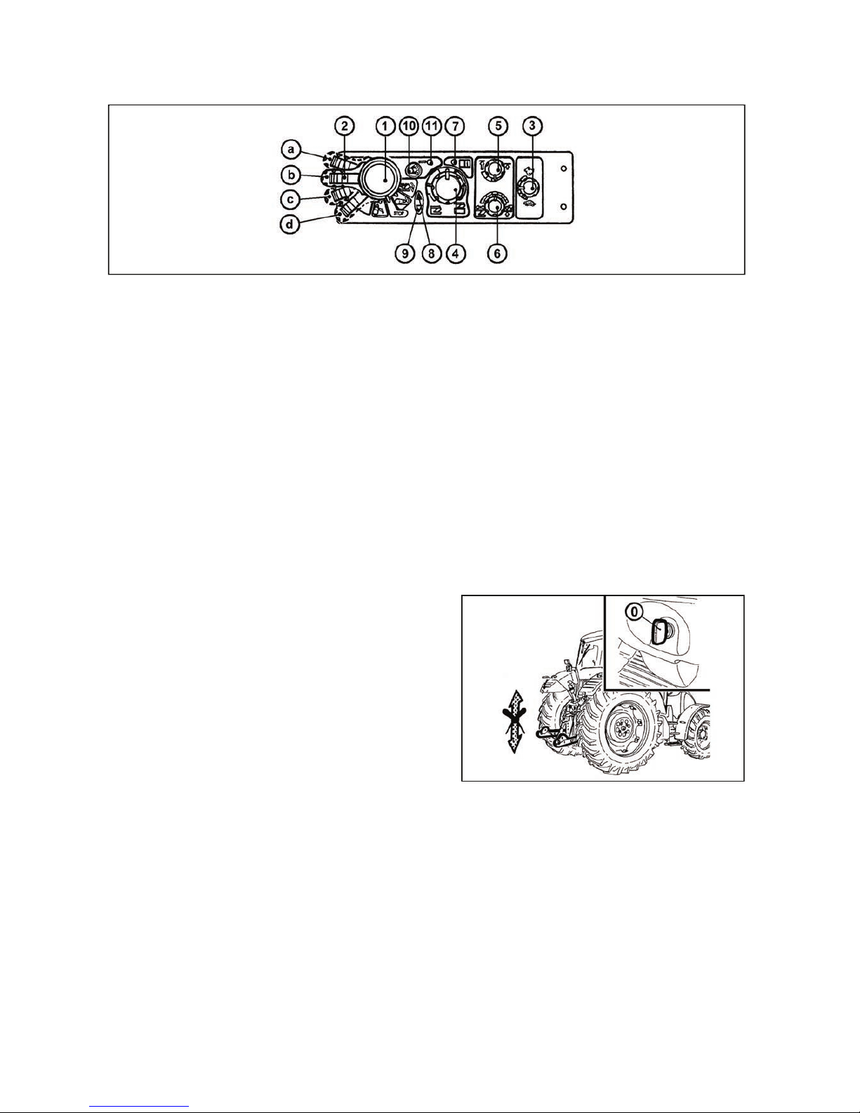
Control element functions
F_02_162
1. Lifting switch
a - Transport, lifting
b - STOP
c - Regularity of lowering (working)
d - Free position, fast sinking- automatic return of lever to (c) position by a spring
2. Blocking (in transport position)
3. Lowering speed
4. Setting the position of lifting device
5. Upper position restriction
6. Smooth setting - of manual control
- automatic control
7. LED - diagnostic
8. LED - lifting
9. LED - lowering
10. Engaging compensator (softening vibrations)
11. LED - softening vibrations engaged
Equipment 'OFF'
Electric installation deactivated with the key of the
switching box. The electronic system is off, the lifting
device is blocked.
F_02_188
ELECTRO-HYDRAULIC SYSTEM
89

Blocking cancellation
Quick sinking
When you switch on the electric installation with the key of
the switching box (I), the lifting device remains blocked
electronically - the lifting and lowering function is
deactivated; on the EHR-B control panel the diagnostic
LED (7) and the vibration dampening LED (11) shortly
light up - the system self-test is in progress. The lifting
LED (8) and the lowering LED (9) are off. After a short
time permanent illumination of the diagnostic LED (7)
indicates the state of EHR-B blocking.
If the diagnostic LED (7) is permanently illuminated, the
control circuits are disconnected.
F_02_164
The engine can only be started if the engine (1)
is in position (b).
The EHR-B electro-hydraulic system is only active when
the engine is started.
Activation of the EHR-B system is only possible when the
lubrication indicator has gone off.
The blocking can only be cancelled (system activated)
with the engine running by moving the lifting lever (1) to
position (a) - short-time switching is sufficient.
By moving the lever (1) to position (c) you will bring the
three-point hitch to the position corresponding to the
element setting, i.e. the current position of controls (4), (5),
(6).
After the activation of the system EHR-B first
for safety reasons limits the lifting speed of the
hydraulic arms. When the hydraulic arms first reach
the selected position, this safety limitation is
cancelled and then the lifting speed of the hydraulic
arms is normal.
F_02_163
Lever (1) in position (d) - free position. You must hold the
lever in this position; after releasing the lever will return to
position (c) - the system works in accordance with the
setting of controls (3), (4), (5) and (6).
F_02_165
ELECTRO-HYDRAULIC SYSTEM
90

Transport of implements
Shift the lifting lever (1) to position 'a' and block it with the moving latch (2).
Blocking the lifting lever (1) by the moving latch (2) in position (a):
A - Lever movement blocked
B - Lever movement not blocked
When the tractor with an attached implement is stopped, the implement must be lowered onto
the ground (it must not be left in the lifted position).
Stop position
Vibration compensator (damper)
F_02_168
It is used during transport of a heavy implement attached to the rear three-point hitch.
After activation of the vibration compensator (10) the arms of the rear three-point hitch sink by approx. 4%,
which allows oscillation of the arms in the range of approx. 8% of the lift. The upward oscillation is always
limited by the position of the upper position limiter (5).
Advantages of active dampening of vibrations during transport of a heavy implement attached to the rear
three-point hitch.
1. Increased operation safety (the steering axle is not unloaded so much
2. Stabilization of the transported implement
3. Reduced dynamic stress of the hydraulic system and the rear three-point hitch
During the adjustment of the hitch for a single-axle semi-trailer the vibration compensator
must be off.
By moving the lever (1) to position (b) - STOP position you will immediately stop the movement of the three-point
hitch.
F_02_167
ELECTRO-HYDRAULIC SYSTEM
91
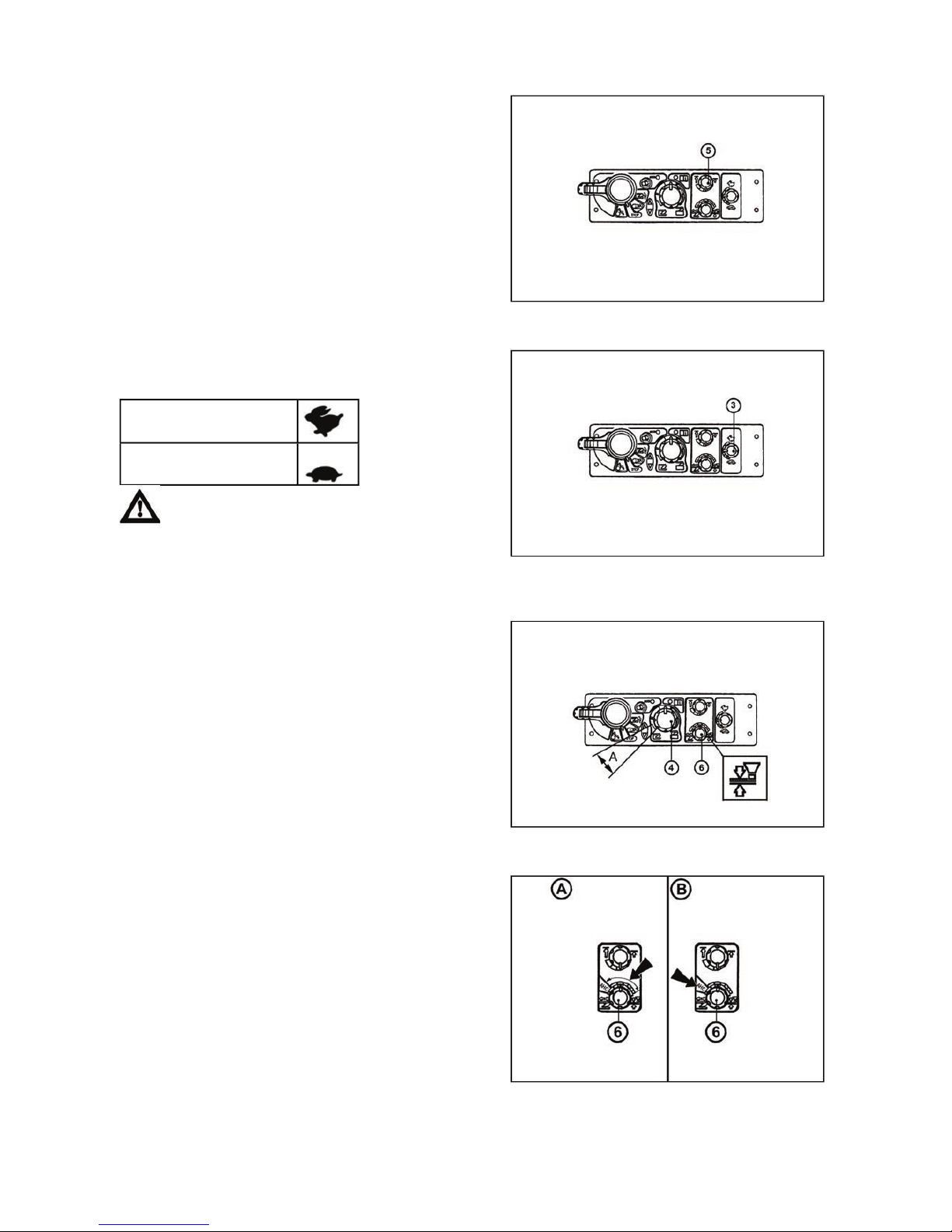
Limitation of the upper position of the three-point hitch
Lowering speed
Free position
Setting the control of three-point hitch
It is activated with the control (5). The limitation can be
implemented in the upper half of the three-point hitch lift.
F_02_169
The lowering speed of the three-point hitch is set with the
control (3).
In the vibration dampening mode and during
the use of the rear control buttons the lowering speed
setting is out of function.
Symbol of the maximum
lowering speed
Symbol of the minimum
lowering speed
F_02_170
For permanent work with free hydraulic system, e.g.
during work with a plough with a support wheel the
position of the control (4) under the indication (A) and the
position of the control (6) at the positional control symbol
is used.
F_02_171
Electrohydraulics enables two ways of three-point hitch
control.
A. Manual control setting - control (6) is set in the range
see arrow
B. Automatic control - control (6) is set in HitchTronic
(AHC) position see arrow
Automatic control can be at any time exchanged for
manual and the other way round by a control (6).
ahc_01
ELECTRO-HYDRAULIC SYSTEM
92

Manual setting of control of three-point hitch
F_02_172a
Perform according to 'Cancel blocking' part and set the required position of elements with regard for the
nature of performed works. To reach the depth of working tools, there is a control (4). For setting the kind of
control and its mixing, use a control (6).
The activity of control (lifting and lowering) can be monitored by means of indication diodes (8) and (9). Na
shift the lever (1) (a) position, after turning, set again to (c) position. Control system takes the previous
working position (memory of ploughing). For setting the required speed of starting, there is a control (3).
Automatic control of three-point hitch
F_02_172a
Do the step according to 'Cancel blocking' part. Set the control (6) to hitchtronic (AHC) position. By control
(4), set the working depth of tools attached to rear three-point hitch.
When the implement attached in the rear three-point hitch reaches the depth set by the control (4), control
system measures the soil resistance and this value is used as default for further control.
The activity of controls (lifting and lowering) can be monitored by means of indicated on diodes (8) and (9).
At dead end, shift the lever (1) to (a) position, after turning set the (c) position again.
For setting the required speed of lowering, there is a control (3).
After reaching the depth set by the control (4) control system again measures the soil resistance and this
value is used as default for further re
g
ulation.
Power control symbol
Position control symbol
ELECTRO-HYDRAULIC SYSTEM
93

Using the rear control
External control buttons of the electro-hydraulic system
The rear control is used to connect and disconnect
implements. The lifting switching lever (1) on the EHR-B
electro-hydraulic control panel must be in position (b) or
(c). The designation symbols of buttons on both the tractor
fenders correspond to the movement direction of the
three-point hitch after their pressing. The movement only
lasts as long as the button is held.
Every use of the rear control causes blocking of the
control system and the 'Blocking cancellation' must be
repeated.
F_02_98
1. Lifting
2. Lowering
The movement only lasts as long as the buttons are held.
External hydraulic control buttons are
functional also without previous activation of
electrohydraulics even in case of electrohydraulics
blockage for the reason of possible failure.
Control the arms of the rear three-point hitch by
external electrohydraulics buttons only at the lower
half of arms lift.
FH12N001
When handling the three-point hitch with the
external control buttons the operator must stand out
of reach of the connected implement to avoid being
caught or injured by the implement.
F_02_65
ELECTRO-HYDRAULIC SYSTEM
94

Indication of EHR-B errors
The electronic part of the electro-hydraulic system
continuously checks proper functioning of th e system.
Possible errors are indicated by repeated flashing
combinations of the diagnostic LED (7).
After the remedy of the error the diagnostic LED (7) goes
off.
Permanent illumination of the diagnostic LED (7) indicates
the state of blocking of the electro-hydraulic system.
F_02_173
Have EHR-B errors repaired by a specialized workshop.
Flashing
combination of the
diagnostic LED (7).
Error category Error description
Long
pause
No.
of
flashes
Short
pause
No.
of
flashes
1x 1x
Serious error
Error with internal safety shutdown of the
electro-hydraulic system - the electrohydraulic system is out of operation - the
work with the tractor must be stopped
1x 2x
1x 3x
1x 4x
1x 5x
1x 6x
2x 2x
Moderately
serious error
Error with internal safety shutdown of the
electro-hydraulic system - the electrohydraulic system is out of operation
2x 3x
2x 4x
2x 8x
3x 1x
Minor error
The electro-hydraulic system work s wit h
a limitation resulting from the error type
3x 2x
3x 4x
3x 6x
ELECTRO-HYDRAULIC SYSTEM
95

Description of minor errors of the EHR-B electro-hydraulic system
F_02_174
Outer hydraulic circu i t
Flashing combination of
the diagnostic LED (7).
Error location Possible cause of the error
Long
pause
No.
of
flashes
Short
pause
No.
of
flashes
3x 1x Right dynamometric pin
(A)
Faulty dynamometric pin
3x 2x Left dynamometric pin (A) Faulty contact or interrupted conductor of the
dynamometric pin
Short-circuit of the dynamometric pin
conductor
Possible overloading of the dynamometric
pin
3x 4x Lowering speed control
(3)
Faulty potentiometer of the control (3)
Faulty contact or interrupted conductor of the
control
3x 6x Control setting switch (6) Faulty potentiometer of the switch (6)
Faulty contact or interrupted conductor of the
switch
It supplies pressure oil for hydraulic devices on outer
drives of hydraulics ended with couplers. Coupler sockets
with 12.5 mm bore are in accordance with the international
recommendation of ISO.
P+13N011
ELECTRO-HYDRAULIC SYSTEM
96

Outer hydraulic circui t controls
P+13N004
Outer hydraulic circuit controls are located on the right wing.
lever (a) controls the section of distributor - quick couplers (1) and (2)
lever (b) controls the section of distributor - quick couplers (3) and (4)
lever (c) controls the section of distributor - quick coup lers (5) and (6)
lever (d) controls the section of distributor - quick couplers (7) and (8)
Quick coupler (0) is directly connected with transmission and it is supposed for recuperative oil of exterior
hydraulic appliances (e.g. from rotary hydraulic engines etc.).
A
ccording to the equipment of the tractor, the following combinations of control levers and quick couplers can
be supplied:
levers (a), (b), (c) and (d) - quick couplers (1), (2) , ( 3), (4), (5), (7) and (8)
levers (a),(b) and (c) - quick couplers (1), (2), (3), (4), (5) and (6)
Quick coupler (0) is supplied in any case.
If the tractor is equipped with front three-point hitch, use lever (b) to control it. When the front
three-point hitch is used, quick couplers cannot be connected as they are pressured together with
the front three-point hitch! When you finish using the front three-point hitch and want to use the
section with quick couplers 3 and 4 with connection to the front three-point hitch, raise the arms of
the front three-point hitch to the transport position and move the front three-point hitch lever to the
'locked' position.
Locking control levers
Outer hydraulic circuit control levers are locked in neutral
(N) position.
To unlock them, raise the lock control (1) and turn it to
a stop point in the direction shown by the arrow.
To lock them again, move the levers to neutral (N) position
and turn the lock control in the opposite direction than
shown by the arrow to a stop point and push the control
down. This locks the lever in neutral position.
For safety reasons, always lock outer hydraulic
circuit levers in neutral position (N).
P+11N014
ELECTRO-HYDRAULIC SYSTEM
97

Different functions of outer hydraulic circuit control levers
P+13N005
There are four positions of the lever (a):
P+13N006
There are four positions of the lever (b):
N - Neutral position. Quick coupler drives (1) and (2) are closed and oil in the hydraulic appliance connected
is blocked. Lever
(a)
is locked in this position.
1 - Pressure in quick coupler (1). Quick coupler (2) is connected with the drain. Lever (a) is locked in this
position. In case pressure exceeds 16.5 MPa when connected to quick coupler (1), lever (a)
automatically returns to (N) position - kick-out function.
2 - Pressure in quick coupler (2). Quick coupler (1) is connected with the drain. Lever (a) is locked in this
position. In case pressure exceeds 16.5 MPa when connected to quick coupler (2), lever (a)
automaticall
y
returns to (N) position - kick-out function.
P - Floating position. Both quick couplers (1) and (2) are connected with the drain and oil is free to flow in
both directions. Lever
(a)
is locked in this position.
N - Neutral position. Quick coupler drives (3) and (4) are closed and oil in the hydraulic appliance connected
is blocked. Lever
(b)
is locked in this position.
3 - Pressure in quick coupler (3). Quick coupler (4) is connected with the drain. It is necessary to hold lever
(b) in this position, when released, lever (b) automatically returns to (N) position. In addition, quick
coupler (3) is equipped with a one-way valve - convenient for connecting a tool which requires higher
degree of impermeability - minimum lowering of the tool during transport.
4 - Pressure in quick coupler (4). Quick coupler (3) is connected with the drain. Lever (b) is locked in this
position.
P - Floating position. Both quick couplers (3) and (4) are connected with the drain and oil is free to flow in
both directions. Lever
(b)
is locked in this position.
ELECTRO-HYDRAULIC SYSTEM
98

P+13N007
There are four positions of the lever (c) which controls quick couplers (5) and (6):
P+13N008
There are four positions of the lever (d) which controls quick couplers (7) and (8):
N - Neutral position. Quick coupler drives (5) and (6) are closed and oil in the hydraulic appliance connected
is blocked. Lever
(c)
is locked in this position.
5 - Pressure in quick coupler (5). Quick coupler (6) is connected with the drain. It is necessary to hold lever
(c) in this position, when released, lever (c) automatically returns to (N) position. In addition, quick
coupler (5) is equipped with a one-way valve - convenient for connecting a tool which requires higher
de
g
ree of impermeability - minimum lowering of the tool during transport.
6 - Pressure in quick coupler (6). Quick coupler (5) is connected with the drain. Lever (c) is locked in this
position.
P - Floating position. Both quick couplers (5) and (6) are connected with the drain and oil is free to flow in
both directions. Lever (c) is locked in this po sition.
N - Neutral position. Quick coupler drives (7) and (8) are closed and oil in the hydraulic appliance connected
is blocked. Lever
(d)
is locked in this position.
7 - Pressure in quick coupler (7). Quick coupler (8) is connected with the drain. It is necessary to hold lever
(d) in this position, when released, lever (d) automatically returns to (N) position. In addition, quick
coupler (7) is equipped with a one-way valve - convenient for connecting a tool which requires higher
de
g
ree of impermeability - minimum lowering of the tool during transport.
8 - Pressure in quick coupler (8). Quick coupler (7) is connected with the drain. Lever (d) is locked in this
position.
P - Floating position. Both quick couplers (7) and (8) are connected with the drain and oil is free to flow in
both directions. Lever
(d)
is locked in this position.
ELECTRO-HYDRAULIC SYSTEM
99
 Loading...