

Zetor Proxima 6421, Proxima 6441, Proxima 7441, Proxima 8421, Proxima 7421 Supplement Operators Manual
...


3
ZETOR
The supplement to the instructions manual for tractors Proxima with engines TIER III that is presented to you includes a description, operation and maintenance of accessories that is different from tractors Proxima with engines
TIER II and from description, operation and maintenance of accessories changed in the course of manufacturing of
Proxima.
Despite the fact that many of you have rich experience with operation of other tractors, please read carefully this
manual. You can find here new information and good advices how to use the best the tractor with various works.
When following these principles of operation and maintenance of the tractor and safety of driving, your tractor will
become reliable partner for years.
We wish you thousands of contented worked off hours.
ZETOR
Brno

4
The data on technical specifications, construction, equipment, materials and appearance are valid at the time of printing. The
manufacturer reserves the right of changes.

5
CONTENTS
Page Page
Preventive daily maintenance............................................... 7
Cooling system ........................................................................ 7
Fluid brakes ............................................................................. 7
Air cleaner................................................................................ 7
Oil tank of hydrostatic steering................................................. 8
Acquaintance with the tractor............................................... 9
Reversible switches, switches and levers ................................ 9
Control panel on the right cab column ................................... 10
Tilting steering wheel ............................................................. 10
Aggregation hole, rear right panel.......................................... 10
∗Lever of shifting of reverse................................................... 11
Lever of shifting of road and reduced speeds ........................ 11
Lever of engagement of the output shaft drive....................... 11
∗Lever of shifting of speed of the output shaft
540 and 1,000 rpm................................................................. 12
∗Lever of shifting of speed of the output shaft
540 and 540E rpm ................................................................. 12
∗Lever of shifting of the reducer of creep speeds .................. 12
Transport use....................................................................... 13
Multi-storey quick-adjustable hitch CBM ................................ 13
Height adjustment and dismounting of the multi-storey hitch
CBM....................................................................................... 13
Automatic guide mouth of the multi-storey hitch CBM
>31/03/2007........................................................................... 14
Automatic guide mouth of the multi-storey hitch CBM
01/04/2007<........................................................................... 14
Modular system of hitches for trailers and semi-trailers......... 15
Module of a swing link bracket............................................... 15
Swing link............................................................................... 15
Module of a swing link bracket with fixed pin ......................... 15
Module of a bracket with ball ø 80mm ................................... 16
Hitch CBM for single-axle trailers........................................... 16
Maximum permissible vertical static loading of hitches for
trailers and semi-trailers ......................................................... 17
Maximum permissible vertical static loading of hitches for
trailers and semi-trailers ......................................................... 18
Drive of agricultural machines ............................................ 19
Front output shaft Zuidberg .................................................... 19
Engagement of the front output shaft Zuidberg ...................... 19
Maximum transferred power................................................... 19
Hydraulic equipment............................................................... 20
External control of rear arms of the hydraulic equipment ....... 20
Hitches .................................................................................. 21
Height adjustment of the lifting links....................................... 21
Fixed and free positions of lower links of the hydraulic
equipment .............................................................................. 21
Limiting links........................................................................... 21
∗Lower links with telescopic terminals.................................... 22
∗Lower links with hooks CBM................................................. 22
∗Front 3-point hitch................................................................. 23
Control of front 3-point hitch ................................................... 23
Adjustment of lifting speed of the front 3-point hitch............... 23
Hydraulic locking of the front 3-point hitch.............................. 24
Working and transport positions of the front 3-point hitch ......24
Electric installation ..............................................................25
Electric equipment.................................................................. 25
Lead battery ........................................................................... 25
Battery disconnector............................................................... 25
Fuse dose (21 fuses).............................................................. 26
Planned technical maintenance.......................................... 27
Oils for 4-cylinder turbo-charged engines Zetor .....................27
Recommended oils for turbo-charged engines according to
ambient temperature .............................................................. 28
Oils to geared mechanisms of tractors................................... 29

6
CONTENTS
Oils for front output shafts Zuidberg....................................... 30
Maintenance instructions.................................................... 31
Opening of the front bonnet ................................................... 31
Maintenance of the dry air cleaner – indicator of clogging ..... 31
Function of the indicator of clogging ...................................... 31
Instructions to maintenance of dry air cleaner ....................... 32
Regeneration of main air cleaner cartridge ............................ 32
Replacement of air cleaner safety cartridge........................... 32
Re-installation of cartridges of the air cleaner........................ 33
Oil tank of hydrostatic steering............................................... 33
Refilling of brake fluid............................................................. 33
Essential technical parameters .......................................... 34
Technical specifications of engines of tractors
Z 6421 - Z 8441 ..................................................................... 34
Max. permitted loading of the front axle Cararro 20.16 Z 6441,
Z 7441, Z 8441 (kg) ............................................................... 35
Forces.................................................................................... 36
Power and consumption ........................................................ 36
Speed of the front output shaft Zuidberg................................ 37
Index ..................................................................................... 38

7
PREVENTIVE DAILY MAINTENANCE
H105 G735 G710
COOLING SYSTEM
Check tightness of joints of the engine
cooling system and amount of cooling
fluid in the expansion tank that is installed on the right side of the engine
and accessible after lifting of the front
bonnet.
Refill the fluid up to the upper line
marked MAX. the minimum permissible
level of the cooling fluid is at the line
marked MIN.
Open the overpressure lid after
the fluid is cooled down! Danger
of scalding!
FLUID BRAKES
Check tightness of fluid brakes, fluid control of the clutch a amount of brake fluid
in the expansion tank that is installed on
the left side of the tractor in front of the
cab and accessible after lifting of the
front bonnet.
Keep level of the brake fluid between 3/4
(max. level) and 1/2 (min. level) of the
tank.
When handling with the brake
fluid, keep strictly all components
clean. Check level of the brake
fluid daily before driving.
AIR CLEANER
Maintenance of the cleaner shall
be carried out after indication of
clogging.
The indicator is accessible after lifting of
the front bonnet. It is installed on the left
side of the air cleaner, close to the elbow
of the air supply pipe.

8
PREVENTIVE DAILY MAINTENANCE
G720
OIL TANK OF HYDROSTATIC
STEERING
Using the gauge rod check level of oil in
the hydrostatic steering tank. The tank is
installed in the front left part of the tractor
and accessible after lifting of the front
bonnet.
Using the gauge rod (A) check level of oil
in the tank of hydrostatic steering; keep
the level between lines marked MIN. and
MAX., see Fig. (A).
Refill oil as necessary, do to it, remove
the nut (1) and lid.
Check condition of all hoses of the hydraulic steering circuit for possible damages and leakage of oil.
Check tightening of all bolts and nuts of
steering rods and levers.

9
ACQUAINTANCE WITH THE TRACTOR
F133
REVERSIBLE SWITCHES, SWITCHES AND LEVERS
a - Switch of lighting (off, parking lights, front headlamps).
b - Switch of low beams in the front mask and low beams on
the cab.
∗ Option: the lights on the cab may be controlled by this
switch independently on the lights in the front mask
(on/off).
c - Switch of the rear fog light (on/off). Function of the fog
light is indicated by an illuminated symbol on the switch.
d - Switch of the rear working headlamp on the cab column
(on/off). Function of the working headlamp is indicated
by an illuminated symbol on the switch.
e - Switch of warning lights.
f - Switch of the front driving axle. Switched on front driving
axle is indicated by an illuminated symbol on the switch.
g - Switch of the light beacon (on/off).
h - Switch of working lights in the front mask (on/off). Func-
tion of the working lights is indicated by an illuminated
symbol on the switch.
i - Switch of the front output shaft (on/off). Function of the
front output shaft is indicated by an illuminated symbol
on the switch. The switch is equipped with a mechanical
catch against unintentional switching. When switching on
press the catch towards the symbol.
j - Pushbutton of the differential lock.
k - Engine stop (stopping device).
l - Switch of direction indicators, low and high beams and
horn and flash light.
m - Ignition box.

10
ACQUAINTANCE WITH THE TRACTOR
H127 F205 H109
CONTROL PANEL ON THE RIGHT
CAB COLUMN
1- ∗ switch of front working lights on the
cab roof
2- ∗ switch of rear working lights on the
cab roof
3- Lighting of the cab
4- two-position switch of the front wiper
and windscreen washer
5- switch of the rear wiper
TILTING STEERING WHEEL
The tilting column of the steering wheel
enables variable adjustment of height and
angle position of the steering wheel.
Height adjustment of the steering
wheel
Adjustment is carried out by extraction or
retraction of the steering wheel after
unlocking of the arrestment by turning of
the lever (1) in direction of the arrow. After
adjustment the lever (1) shall be locked by
tightening of the lever against direction of
the arrow.
Angle adjustment of the steering wheel
Adjustment is carried out by tilting of the
steering wheel after unlocking of the arrestment by turning of the lever (2) in direction of the arrow. After adjustment the
lever (2) shall be tightened against direction of the lever.
AGGREGATION HOLE, REAR RIGHT
PANEL
The lower window is fixed, with a hole for
connection of controllers of the aggregated implement (1).
The right rear panel includes a compartment for a PET bottle (2), 3-pin socket
12V (3) and cigarette lighter (4).

11
ACQUAINTANCE WITH THE TRACTOR
E149 E150 H170
∗LEVER OF SHIFTING OF REVERSE
F - driving forward; kever in forward posi-
tion
N – neutral position
R - driving backward; lever in backward
position
Shifting is carried out when the tractor is
in stillstand.
LEVER OF SHIFTING OF ROAD AND
REDUCED SPEEDS
R
road gears
N
neutral position
S
reduced gears
Shifting is carried out when the tractor is
in stillstand.
LEVER OF ENGAGEMENT OF THE
OUTPUT SHAFT DRIVE
a -
dependent speed of the output
shaft drive through the gearbox;
the speed depends on the engaged gear
n -
neutral position
b -
independent speed of the output
shaft drive - the speed depends
on the speed of engine
Shifting is carried out when the tractor is
in stillstand.

12
ACQUAINTANCE WITH THE TRACTOR
H171 H171 H171
∗LEVER OF SHIFTING OF SPEED OF
THE OUTPUT SHAFT
540 AND 1,000 RPM
a -
540 rpm
n -
neutral position
b -
1,000 rpm
Shifting is carried out when the tractor is
in stillstand.
Shifting of 540 and 1,000 rpm is
possible regardless to the installation of a 6- or 21-spline terminal. The output shaft speed and
type of the terminal shall be chosen depending on the prescribed
speed of the aggregated machine.
∗LEVER OF SHIFTING OF SPEED OF
THE OUTPUT SHAFT
540 AND 540E RPM
a -
540 rpm
n -
neutral position
b -
540E rpm
The gear 540 E is used to achieve 540
rpm of the output shaft when preserving
economical speed of the engine.
Shifting is carried out when the tractor is
in stillstand.
Shifting of 540 a 540E rpm is
possible regardless to the installed 6- or 21-spline terminal.
The output shaft speed and type
of the terminal shall be chosen
depending on the prescribed
speed of the aggregated machine.
∗LEVER OF SHIFTING OF THE
REDUCER OF CREEP SPEEDS
a -
reducer of creep speeds
n -
neutral position
b -
normal speeds
Shifting is carried out when the tractor is
in stillstand.

13
TRANSPORT USE
D201 D202
MULTI-STOREY QUICK-ADJUSTABLE
HITCH CBM
It is used for hitching of two-axle of light
single-axle trailers. The guide mouth is
height-adjustable. When working with
various agriculture machines the height
of the hitch shall be adapted as necessary or dismount at all.
HEIGHT ADJUSTMENT AND
DISMOUNTING OF THE MULTISTOREY HITCH CBM
Turning of the lever in direction of the arrow to the position (1) unlocks the lever
and its subsequent turning to the position
(2) slides the arrestment pins (3) in; this
releases the multi-storey hitch and its
height can be adjusted or the hitch dismounted.
Release of the lever from the position (2)
slides the arrestment pins (3) out and the
lever returns automatically to its initial
position.

14
TRANSPORT USE
D203 E304
AUTOMATIC GUIDE MOUTH OF THE
MULTI-STOREY HITCH CBM
>31/03/2007
Moving of the lever (1) in direction of the
arrow slides the pin (3) into its upper position that is indicated by the extracted
warning indicator (4), see Fig. (A).
After sliding of the guide mouth onto the
thill eye the pin slides automatically into
the thill eye of the connected trailer. The
hitch pin (3) can be lowered manually by
moving of the lever (2) in direction of the
arrow. Sliding of the pin in is indicated by
retracted warning indicator (4), see the
Fig. (B).
After hitching of the trailer always
check retraction of the warning
indicator as shown on Fig. (B).
AUTOMATIC GUIDE MOUTH OF THE
MULTI-STOREY HITCH CBM
01/04/2007<
Moving of the lever (1) in direction of the
arrow (a) slides the pin (2) into its upper
position that is indicated by the extracted
warning indicator (3), see Fig. (A).
After sliding of the guide mouth onto the
thill eye the pin slides automatically into
the thill eye of the connected trailer. The
hitch pin (2) can be lowered manually by
moving of the lever (1) in direction of the
arrow. Sliding of the pin in is indicated by
retracted warning indicator (3), see the
Fig. (B).
After hitching of the trailer always
check retraction of the warning
indicator as shown on Fig. (B).
15
TRANSPORT USE
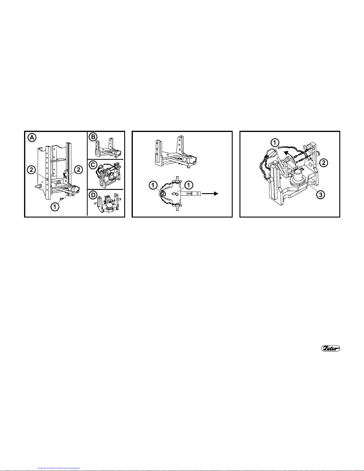
D204 D205 D206
MODULAR SYSTEM OF HITCHES FOR
TRAILERS AND SEMI-TRAILERS
Types of modules:
Fig. (B) – Swing link bracket
Fig. (C) – Swing link bracket with fixed
pin (piton fix)
Fig. (D) – Bracket with ball ø 80mm
Dismounting, Fig. (A):
1- Remove the locking screw (1).
2- Secure the module against drop,
unlock and remove the pins (2).
3- Slide the module downward, out of
the bracket.
Mounting is carried in reverse order.
MODULE OF A SWING LINK
BRACKET
The module of the swing link bracket is
installed in the multi-storey hitch bracket.
SWING LINK
Dismounting:
1- Unlock and remove the pin (1).
2- Slide the swing link out in direction of
the arrow.
Mounting is carried in reverse order.
MODULE OF A SWING LINK
BRACKET WITH FIXED PIN
Carry out dismounting and mounting of
the swing link as described in “Swing
link”.
Connection of the eye to the fixed pin (3):
1- Unlock and remove the pin (1)
2- Lift the locking wedge (2) in direction
of the arrow.
3- Fit the thill fixed eye onto the fixed
pin (3)
4- Give the locking wedge (2) back into
its original position and lock it using
the pin (1).

16
TRANSPORT USE
D207 D208
MODULE OF A BRACKET WITH BALL
Ø 80MM
The bracket with a ball ø 80mm is
used only for hitching of semitrailers with hitching devices designed for balls ø 80mm.
Fig. (A) – Unlocking of the hitch:
Move the lever (1) in direction of the arrow to push away the locking wedge (2).
Fig. (B) – Locking of the hitch:
Move the lever (1) in direction of the arrow to pull up the locking wedge (2).
HITCH CBM FOR SINGLE-AXLE
TRAILERS
The hitch for single-axle trailers can be
fitted with a hook (A) or swing link (B).
Replacement of the hook for the swing
link (C):
1- Lower the hitch.
2- Unlock and remove the pin (1).
3- Remove the hook in direction of the
arrow.
Mounting of the swing link is carried out
in reverse order.
17
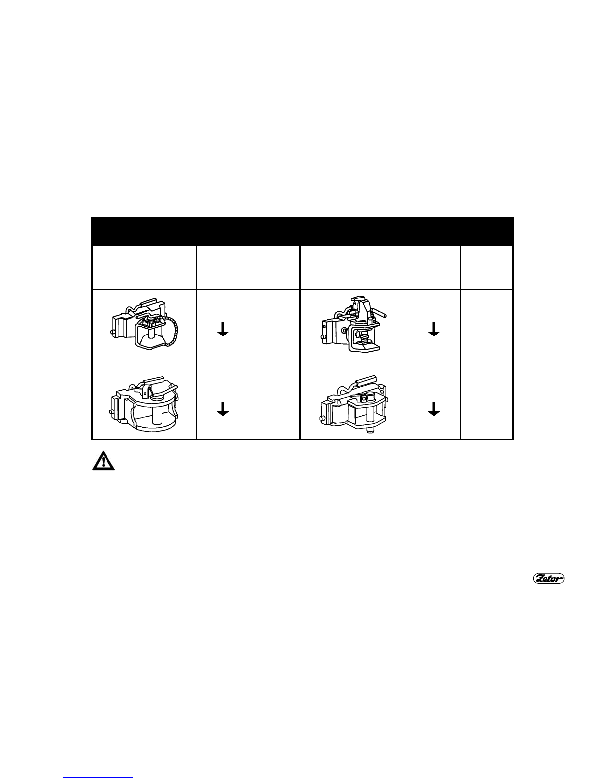
TRANSPORT USE
MAXIMUM PERMISSIBLE VERTICAL STATIC LOADING OF HITCHES FOR TRAILERS AND
SEMI-TRAILERS
Type of hitch
Permissible
vertical
static load-
ing
Hitch pin
Ø
Type of hitch
Permissible
vertical
static load-
ing
Hitch pin
Ø
2,000kg
31mm
2,000kg
38mm
2,000kg
43mm
2,000kg
28mm
The maximum weight of the aggregated braked trailer or semi-trailer shall not exceed the value
given on the serial rating plate of the tractor and value given in the technical passport (MOT certificate). The maximum speed of the vehicle combination is given by the maximum permissible
speed of the slower vehicle in the combination.
18
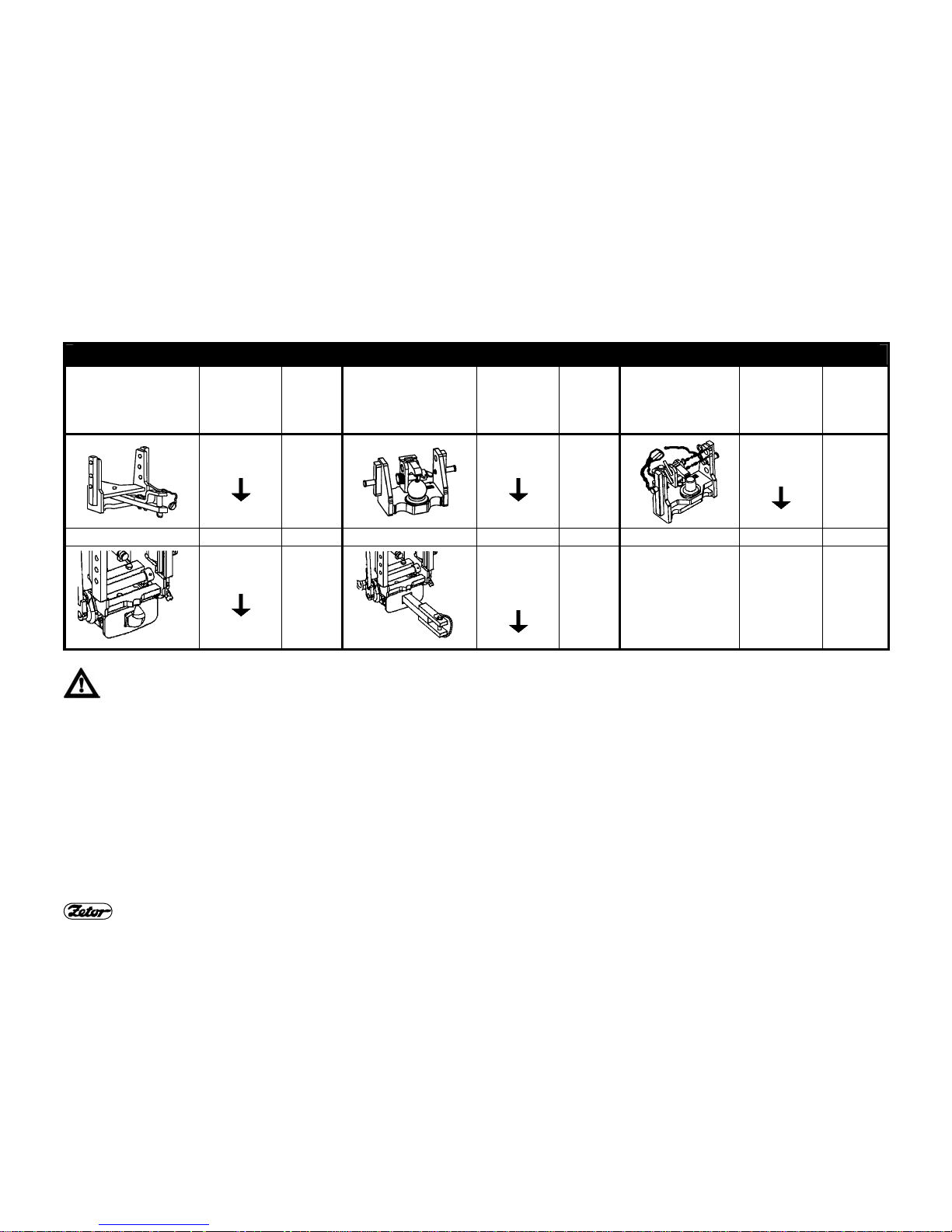
TRANSPORT USE
MAXIMUM PERMISSIBLE VERTICAL STATIC LOADING OF HITCHES FOR TRAILERS AND SEMI-TRAILERS
Type of hitch
Permissible
vertical
static load-
ing
Hitch
pin
(ball) Ø
Type of hitch
Permissible
vertical
static load-
ing
Hitch
pin
(ball) Ø
Type of hitch
Permissible
vertical
static load-
ing
Hitch pin
(ball) Ø
736kg
31 mm
3,000kg
80 mm
fixed pin
2 000kg
44.5 mm
3,000kg
47 mm
1,200kg
32 mm
The maximum weight of the aggregated braked trailer or semi-trailer shall not exceed the value given on the serial rating
plate of the tractor and value given in the technical passport (MOT certificate). The maximum speed of the vehicle combination is given by the maximum permissible speed of the slower vehicle in the combination.

19
DRIVE OF AGRICULTURAL MACHINES
E356 H355 E358
FRONT OUTPUT SHAFT ZUIDBERG
The front output shaft is equipped with a
fixed 21-spline terminal and its speed is
1,000 rpm only.
The tractor may be equipped with an optional front output shaft with both directions of rotation:
a -
in direction of rotation of the engine (standard)
b -
against direction of rotation of the
engine (∗optional)
ENGAGEMENT OF THE FRONT
OUTPUT SHAFT ZUIDBERG
The front output shaft Zuidberg can be
engaged and disengaged using a switch
on the dashboard. Activation of the
switch is indicated by the illuminated
symbol on the switch.
The switch is fitted with a mechanical
lock (1) against unintentional switching
on. When activating the switch, depress
also the lock (1) in direction of the arrow.
The switch shall be off when
starting the engine.
MAXIMUM TRANSFERRED POWER
Output shaft Transferred
power
front (Zuidberg)
1,000 rpm 45kW*
rear
1,000 rpm full engine power
540 rpm full engine power
540E rpm full engine power
*In case of a transfer of power without
shocks, the value of the transferred
power may be increased to 50kW.

20
HYDRAULIC EQUIPMENT
G419 G161
EXTERNAL CONTROL OF REAR ARMS OF THE HYDRAULIC EQUIPMENT
External control of rear arms of the hydraulic equipment can be found on the rear
right mud guard and allows the driver easier hitching of the implement, as movement
of the lower links of the 3-point hitch can be controlled from outside. It is used only for
hitching and unhitching of agricultural implement.
Fig. (A):
Before use of the external control move the regulation lever (1) to the position P.
Move the sliding stop of the inner hydraulic circuit lever (2) to the front extreme position.
Fig. (B): Lowering of arms of the hydraulic equipment
Move the lever (3) in direction of arrows (move of the lever is limited by the rocker
arm). Repeating of this procedure lowers the hydraulic arms in small steps.
Fig. (C): Lifting of arms of the hydraulic equipment
Move the lever (3) in direction of arrows (move of the lever is limited by the rocker
arm). Repeating of this procedure lifts the hydraulic arms in small steps.
During manipulation with the 3point hitch using the external control the worker shall stand outside
the area of the hitched implement
to prevent his catching and/or injure.

21
HITCHES
E453 E454 E455
HEIGHT ADJUSTMENT OF THE
LIFTING LINKS
Fig. (A) – Left lifting link:
After disconnection of the arm upper end
from the hydraulic equipment pin turn the
eye (1) to adjust the height.
Fig. (B) – Right lifting link:
Slide out the handles (2) in direction of
the arrow (2) and adjust the height.
FIXED AND FREE POSITIONS OF
LOWER LINKS OF THE HYDRAULIC
EQUIPMENT
Fig. (A) – Fixed position of lower links of
the hydraulic equipment:
The pin head (1) and washer (2) are
mounted horizontally.
Fig. (B) – Free position of lower links of
the hydraulic equipment:
The pin head (1) and washer (2) are
mounted vertically.
Free position enables free hitching of agricultural implement. The end of either
link may move independently on the
height of the other link.
LIMITING LINKS
The limiting links (1) enable side swings
of the lower links.
The left and right limiting links can be adjusted by turning of the link tube, see the
arrow.
Both limiting links shall always be
mounted on the tractor.

22
HITCHES
E459 E460
∗LOWER LINKS WITH TELESCOPIC
TERMINALS
The lower links of the hitch are equipped
with semi-automatic telescopic terminals
CBM that facilitate hitching of the implement to the tractor. After pulling out the
locking pins (1) slide out the terminals
(2). These terminals then can be fastened to the fixing pins of the carried implement.
After hitching of the carried implement,
release arms of the hydraulic equipment.
By lowering of the arms and reversing of
the tractor backward the terminals (2)
slide into the links and lock themselves
automatically in their working position using the locking pins (1).
Check always position of the
telescopic terminals, see Fig. (3).
∗LOWER LINKS WITH HOOKS CBM
The lower (3) and upper (4) links of the
hitch are fitted with hooks CBM.
First the implement shall be fitted with
hitching balls CBM (1) and the distance
between the lower links (3) of the hitch
shall be adjusted by limiting links.
During reversing and lifting of the 3-point
hitch its lower links (3) are connected to
the implement and then the driver connects the upper link (4) of the 3-point
hitch from his cab.
For disconnection of the implement
unlock the hooks, using the control wires
(2) lift the upper link (4) and by lowering
of the 3-point hitch disconnect the lower
links (3).

23
HITCHES
E461 H462 E463
∗FRONT 3-POINT HITCH
It is designed for hitching of front-carried
agricultural machines and implement
acc. to ISO 8759-2.
When transporting a carried implement it is always necessary to
lock the hitch in its lifted position
using hydraulic valves that are
installed on the left side of the
tractor, above the front axle.
This hydraulic locking is recommended
even in case that no implement is
hitched in the 3-point hitch.
CONTROL OF FRONT 3-POINT HITCH
The hitch is equipped with two singleacting hydraulic cylinders supplied with oil
from the additional distributor of hydraulic
pressure. Lifting and lowering is carried out
by the lever (1) of the additional distributor
controller.
position 6
lifting
position 5
lowering
position N
locking of the hitch
ADJUSTMENT OF LIFTING SPEED OF
THE FRONT 3-POINT HITCH
Before you start any work with the implement hitched on the front 3-point
hitch, it is recommended to adjust the
throttling valve (3) so that the time that is
necessary for lowering of the implement
from the highest to the lowest position is
1 to 1.5 second. Turning of the valve
body to the left (in direction of the arrow)
increases speed of lowering. When adjusting the speed, the levers of valves of
the front hitch shall be in horizontal positions.

24
HITCHES
E461 E466
HYDRAULIC LOCKING OF THE
FRONT 3-POINT HITCH
Hydraulic locking of the front 3-point
hitch can be carried out in any position of
the hydraulic cylinders using valves in
the front part of the tractor (2).
A
Free position:
Levers of the valves are in horizontal positions.
- The hitch can be controlled
from the cab.
B
Locked position:
Levers of the valves are in vertical positions.
- The hitch is locked.
The upper lever of the hydraulic lock
valve of the front 3-point hitch is fitted
with arrestment. Before moving the upper lever to another position, unlock the
lever by its pulling out of the hydraulic
lock valve body.
Carry out locking and unlocking
of the front 3-pint hitch always by
both levers!
WORKING AND TRANSPORT
POSITIONS OF THE FRONT 3-POINT
HITCH
A
Working position of the front 3point hitch
B
Transport position of the front 3point hitch
Change of positions of the front 3-point
hitch links:
1. Unlock and remove the pin (1) from
the hole.
2. Lift the arm from position (A) to position (B).
3. Lock the arm using the pin in the hole
(2) and lock the pin as well.
Insert only the pin into the hole;
never check the hole by fingers!

25
ELECTRIC INSTALLATION
D305 D302
ELECTRIC EQUIPMENT
Nominal voltage,
grounded (minus (-)
pole
12 V
Battery
12V/155Ah
Alternator with builtin voltage regulator
14V / 95A
Starter with reducer
12V / 3 kW
V-belts of the alternator and water
pump drives
AVX10x1385
Laservice
LEAD BATTERY
The lead battery is located under cover
on the left side of the tractor, under the
cab footboard.
The lead battery is accessible after tilting
out the cab footboard.
When tilting out the can footboard the cab door shall be
closed.
1- Remove the screw (1).
2- Lift the footboard in direction of the
arrow.
3- Lock the lifted footboard by the screw
in the footboard hole (2).
4- Remove the lock pin (3).
5- Take the cover lower edge and lift
and remove it.
BATTERY DISCONNECTOR
The battery disconnector (1) is installed
on the left side of the tractor, close to the
starter.
a- Battery connected
b- Battery disconnected
When lying by the tractor, disconnect the battery using the battery disconnector (1). This interrupts permanent minimal withdrawal of electric power by the
breaker of warning lights (approx.
10 mA).
In case the tractor is laid by for a
longer period, it is necessary to
recharge the battery at least
every three months due to its
self-discharging.
26
ELECTRIC INSTALLATION
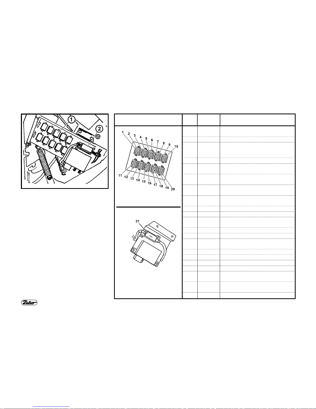
F306
FUSE DOSE (21 FUSES)
It is accessible after removal of the steering console left cover.
The fuses (1) are knife type and should
be replaced only for fuses with the same
rating. In case of repeated blowing seek
the nearest service shop.
The fuse of glowing (2) is a strip type
with rating 80A.
Location of the fuses in the
fuse dose
Pos. Fuse
rating
Protected system
1 15A Interrupter of warning lights
Stop lights
2 15A Horn, light beacon
3 15A Control of front diving axle, control
of differential lock, dashboard
power supply
4 15A High beams with indicator
5 15A Left side marker lights, dashboard
illumination, registration plate lights
6 15A obrysová světla pravá, zadní pra-
covní světlomet s kontrolkou
7 15A tlumená světla pravá, mlhovka
s kontrolkou
8 7,5A Right side marker lights,
Indicator of lifgts in the mask/roof
9 15A Working lights in the front mask
10 3A Front output shaft Zuidberg
11 15A Front and rear wipers, washer, ra-
dio “15“
12 20A Heating fan, radio “30“
13 15A Recirculation, cigarette lighter
∗14
7,5A Air-conditioning(clutch of compres-
sors)
15 15A Not used
16 15A Not used
17 15A Compressor of driver’s seat
18 20A 3-pin socket
∗19
15A Front working headlamps on the
roof
∗20
15A Rear working headlamps on the
roof
D307
21 80A Glowing
27
PLANNED TECHNICAL MAINTENANCE
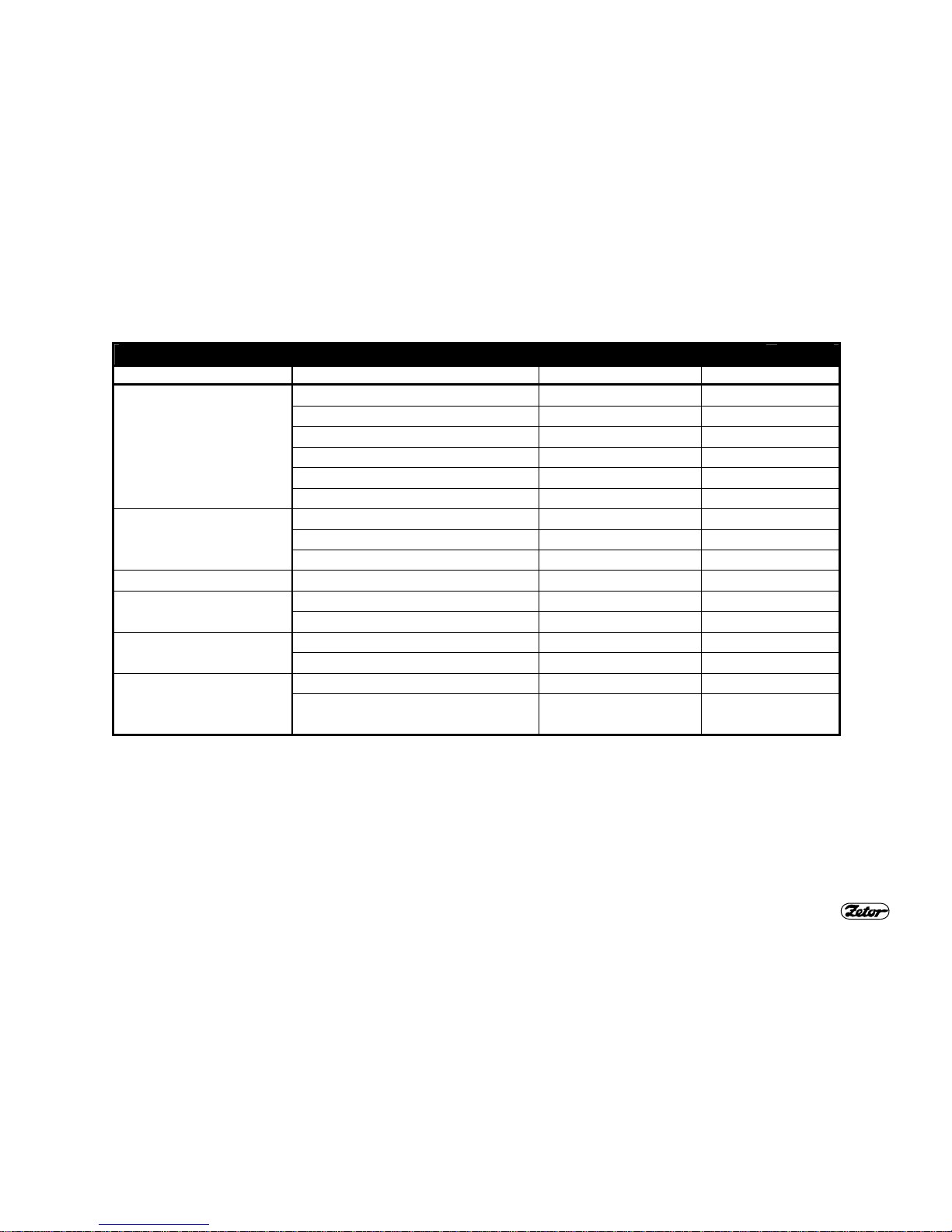
OILS FOR 4-CYLINDER TURBO-CHARGED ENGINES ZETOR TAB. 1
Producer Commercial name of oil Viscosity class SAE Power class API
ÖMV Truck M plus 15W/40 CF-4/SG
Truck FE plus 10W/40 CF-4
Truck FE 10W/40 CE/SG
Austrotrac 10W/30 CE
Truck LD 15W/40 CE
RME Plus 15W/40 CE/SG
Paramo Pardubice M7ADS III-Trysk 20W/40 SF/CD+
M7ADS III-Trysk Super 15W/40 SG/CE
M7ADS IV-Trysk Super Turbo 15W/40 SG/CF-4
Shell Rimula X 15W/40 SG/CF-4
Aral Multi Turboral 15W/40 CF-4/SH
Super Traktoral 10W/30 CD-CE/SF
Koramo Kolín Mogul Diesel DTT Plus 10W/40 CF-4/SG
Mogul Traktol STOU 10W/30 CE/SF
Fuchs Plantmot (bio-oil) 5W/40 CD/SG
Titan Hydramot 1040MC
Titan Truck
10W/40
15W/40
CD/SG
CG4

28
PLANNED TECHNICAL MAINTENANCE
RECOMMENDED OILS FOR TURBO-CHARGED ENGINES ACCORDING TO
AMBIENT TEMPERATURE
Ambient temperature
Viscosity class SAE Power class API
under -7°C 10W/30
10W/40
CD+, CE, CF-4
+30°C to -7°C 15W/30
15W/40
20W/30
20W/40
CD+, CE, CF-4
over +30°C 20W/30
20W/40
20W/50
CD+, CE, CF-4
29
PLANNED TECHNICAL MAINTENANCE
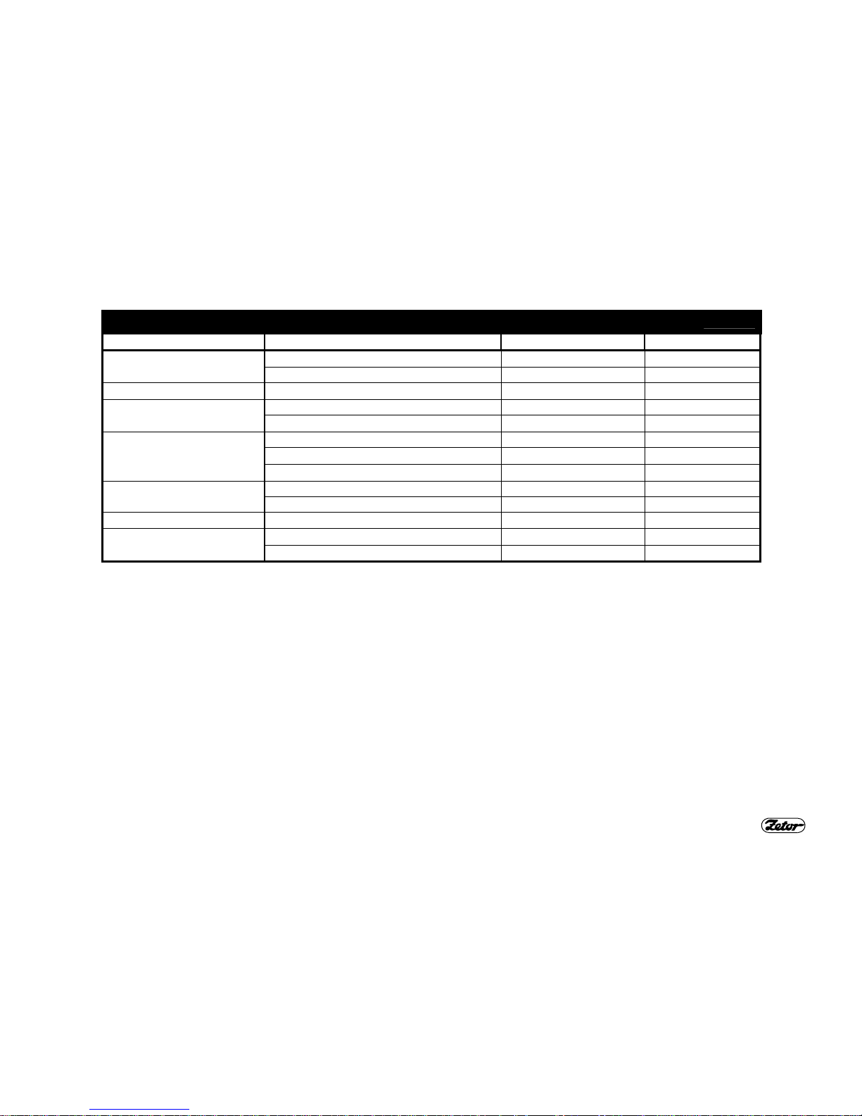
OILS TO GEARED MECHANISMS OF TRACTORS TAB. 2
Producer Commercial name of oil Viscosity class SAE Power class API
Paramo Pardubice Gyrol - UTTO 80W GL-4
Gyrol - PP80 80W GL-4
Esso Torque Fluid 62 80W
GL-4 •
Koramo Kolín Mogul Trans 80 80W GL-4
Mogul Traktol UTTO/EKO 80W
GL-4 ••
Aral EP 80 80W GL-4
Fluid HGS 80W
GL-4 •
Super Traktoral 10W/30
GL-4 ••
ÖMV Austromatic HGN 80W GL-4
Getriebeol MP 80W - 85W GL-4
Shell Donax TT 80W
Fuchs Titan Hydramot 1030MC 10W/30
GL-4 ••
Renolin G 100 80W GL-4
• - Additive oil with additive for differential, with limited slipping and wet brakes
•• - Universal oil
30
PLANNED TECHNICAL MAINTENANCE
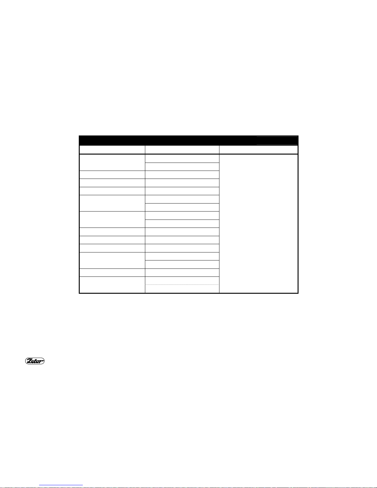
OILS FOR FRONT OUTPUT SHAFTS ZUIDBERG
TAB. 3
Producer Commercial name of oil Interval of oil replacement
BP Autran DX III
Fluid 9
Shell Donax TX
Esso ATF E 25131
Castrol Transmax S
Elf Elfmatic G2 Syn
Elfmatic G3
FINA Finamatic HP
Finamatic S6726
Mobil Mobil ATF
Texaco Texamatic 7045
Valvoline ATF Dextron II-E
Beverol Dextron II-E
(Fina)matic HP
JD Hygard JDMJ 20C
Total Fluide AT42
Fluidematic Syn
Every 450 Mh
(engine operation hours)
31
MAINTENANCE INSTRUCTIONS
G701 G710 G711
OPENING OF THE FRONT BONNET
Opening of the bonnet:
Unlock the bonnet by pressing the
pushbutton (1) and lift it in places of the
arrows.
The bonnet is kept in lifted position using
a gas-fluid strut.
Closing of the bonnet:
Take the bonnet in places of the arrows
and press it down until the lock clicks.
Rapid closing of the bonnet may
damage filaments of the headlamp bulbs in the front bonnet.
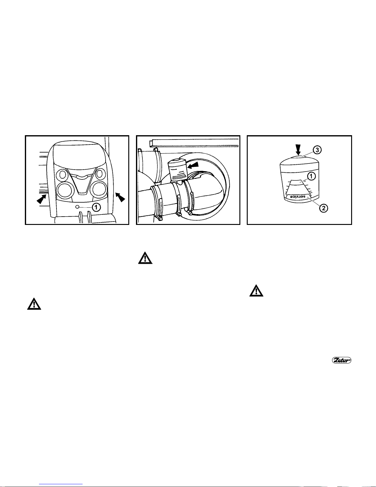
MAINTENANCE OF THE DRY AIR
CLEANER – INDICATOR OF
CLOGGING
Maintenance of the cleaner shall
be carried out when clogging is
indicated.
The indicator is accessible after tilting of
the engine front bonnet. It can be found
on the left side of the air cleaner, close to
the suction pipe elbow.
FUNCTION OF THE INDICATOR OF
CLOGGING
The level of clogging of the air filter is indicated by position of the slider (1) in the
window. In case the indicator (1) reaches
the red field service (2), it is necessary
to carry out maintenance of the dry air
cleaner.
After completion of maintenance
of the dry air cleaner restore correct function of the indicator of
clogging.
Press the lid on the indicator body (3) in
direction of the arrow; this unlocks mechanically the slider (1) that returns to its
initial position and restores function of
the indicator.

32
MAINTENANCE INSTRUCTIONS
G712 G713 G714
INSTRUCTIONS TO MAINTENANCE
OF DRY AIR CLEANER
Carry out maintenance of the air cleaner
as follows:
1- Lift up the front bonnet.
2- Release the air cleaner lid clips (see
the arrows).
3- Remove the air cleaner cover (1).
REGENERATION OF MAIN AIR
CLEANER CARTRIDGE
Pull out the main cartridge of the dry
cleaner (2).
Unless the main cartridge is damaged
(no dust may be on the inner side of the
cartridge), carry out regeneration of the
cartridge by purging from the inner side
of the cartridge using compressed air.
The main cartridge may be regenerated
up to three times. The cartridge shall be
replaced once per year.
REPLACEMENT OF AIR CLEANER
SAFETY CARTRIDGE
Pull out the safety cartridge of the dry air
cleaner (3).
The safety cartridge cannot be regenerated. It shall be always replaced in the following cases:
- damage of the main cartridge,
- after 5 maintenances of the air
cleaner,
- at least once per two years.

33
MAINTENANCE INSTRUCTIONS
G715 G720 G735
RE-INSTALLATION OF CARTRIDGES
OF THE AIR CLEANER
Carry out this operation in the reverse
order.
When re-installing the cartridges, pay attention to the following.
- cleanness of the contact surfaces,
- the cartridges must not be deformed
and must not vibrate after installation;
- perfect tightness of the whole air
cleaner shall be ensured after closing
the cover;
- After completion of maintenance of the
dry air cleaner restore correct function
of the indicator of clogging.
OIL TANK OF HYDROSTATIC
STEERING
The tank is installed in the left side of the
tractor and accessible after lifting of the
front bonnet.
Using the oil-gauge rod (A) check level
of oil in the hydrostatic steering tank;
keep the level between the marks MIN.
and MAX., see Fig. (A).
After removing the nut (1) and tank lid refill oil as necessary.
REFILLING OF BRAKE FLUID
The tank is installed in the left side of the
tractor and accessible after lifting of the
front bonnet.
Keep the brake fluid level between 3/4 of
the tank capacity (max.) and 1/2 of the
tank capacity (min.).
When handling with brake fluid
pay special attention to cleanness. Check the brake fluid level
before each drive.

34
ESSENTIAL TECHNICAL PARAMETERS
TECHNICAL SPECIFICATIONS OF ENGINES OF TRACTORS Z 6421 - Z 8441
Type of tractor Z 6421/Z 6441 Z 7421/Z 7441 Z 8421/Z 8441
Type of engine 7205 1105 1205
Engine compression ignition, 4-stroke cycle, direct fuel injection, turbo-
charged
Engine design in-line, vertical, water-cooled
Number of cylinders 4
Stroke volume cm3 4156
Bore x stroke mm 105x120
Nominal speed min-1 2,200
Order of injection 1-3-4-2
Compression ratio 17
Max. override speed min-1 2,460
Idle speed min-1 800±25
Net power at nominal speed,
measured acc. to ISO 2288
kW 45 53 60
Specific fuel consumption at
the given power
g.kW
-1.h-1
257 255 257
Max. torque (Mt) Nm 265 310 351
Excess of Mt % 35 35 35
Lubrication of engine Pressure system with gear pump
Max. consumption of oil after
100 Mh of engine running-in
g.kW
-1.h-1
0.7 0.7 0.7
Pressure of oil at engine
nominal speed and temperature of oil 80 °C
MPa 0.2 - 0.5 0.2 - 0.5 0.2 - 0.5
Minimum pressure of oil at
750 rpm and oil temp. 80 °C
MPa 0.05 0.05 0.05
Max. temp. of cooling fluid °C 106

35
ESSENTIAL TECHNICAL PARAMETERS
Technical specifications of engines of tractors Z 6421 - Z 8441
Type of engine 7205 1105 1205
Valve gear OHV
Oil cleaner full-flow, disposable
Fuel cleaner single-stage with replaceable cartridge
Type of injection pump PP 4M 10P1i 3782 PP 4M 10P1i 3781 PP 4M 10P1i 3780
Type of nozzles DOP150S428-4104 DOP150S428-4104 DOP150S428-4104
Injectors opening pressure MPa 25-0.8
Angle of injections advance ° 12
Valve play of cold engine:
− inlet valve
− exhaust valve
mm
mm
0.25±0.05
0.25±0.05
0.25±0.05
0.25±0.05
0.25±0.05
0.25±0.05
MAX. PERMITTED LOADING OF THE FRONT AXLE CARARRO 20.16 Z 6441, Z 7441, Z 8441 (KG)
Wheel track (mm)
Travel speed
km.h
-1
1,525 1,610 – 1,620 1,680 – 1,690 1,760 – 1,770 1,825 – 1,835
8
4,000 4,000 4,000 3,800 3,600
20
3,000 3,000 3,000 2,800 2,600
30
3,000 3,000 3,000 2,800 2,600
40
2,500 2,500 2,500 2,500 2,500
Note:
Loading is applicable with regard to the axle itself; the permissible loading with regard to tyres is given in the tab. “Loadcarrying capacity of front tyres”.

36
ESSENTIAL TECHNICAL PARAMETERS
FORCES
Type of tractor Z 6441 Z 7441 Z 8441
Type of engine 7205 1105 1205
Lifting force at end of lower links of the rear 3-point hitch,
within full stroke, at max. usable pressure
- with one auxiliary cylinder (kN)
- With two auxiliary cylinders (kN)
26.4
34.4
41.5
Lifting force at end of lower links of the front 3-point hitch,
within full stroke, at max. usable pressure (kN) 23
POWER AND CONSUMPTION
Type of tractor Z 6441 Z 7441 Z 8441
Type of engine 7205 1105 1205
Power on output shaft (kW±2%)
- at nominal speed engine and shifted speed 1,000 rpm of the
output shaft
New engine having 100 Mh max. 38.5 45.5 52
Run-in engine (over 100 Mh 40.5 48 54.5
Specific consumption of fuel (g.kW-1.h-1±2%)
- corresponding to the power above 260.7 251.5 279.1

37
ESSENTIAL TECHNICAL PARAMETERS
SPEED OF THE FRONT OUTPUT SHAFT ZUIDBERG
Direction of
rotation
Speed of the output shaft / speed of engine Speed of the output shaft / speed of engine
right (a)
1,000 / 1,920 1,146 / 2,200
∗left (b)
1,000 / 2,000 1,100 / 2,200
∗ – optional
E801

38
INDEX
A
Acquaintance with the tractor 9
Adjustment of lifting speed of the front 3-point hitch 23
Aggregation hole, rear right panel 10
Air cleaner 7
Automatic guide mouth of the multi-storey hitch CBM
>31/03/2007
14
Automatic guide mouth of the multi-storey hitch CBM
01/04/2007<
14
B
Battery disconnector 25
C
Control of front 3-point hitch 23
Control panel on the right cab column 10
Cooling system 7
D
Drive of agricultural machines 19
E
Electric equipment 25
Electric installation 25
Engagement of the front output shaft Zuidberg 19
Essential technical parameters 34
External control of rear arms of the hydraulic equipment 20
F
Fixed and free positions of lower links of the hydraulic
equipment
21
Fluid brakes 7
Forces 36
Front 3-point hitch 23
Front output shaft Zuidberg 19
Function of the indicator of clogging 31
Fuse dose (21 fuses) 26
H
Height adjustment and dismounting of the multi-storey hitch
CBM 13
Height adjustment of the lifting links 21
Hitch CBM for single-axle trailers 16
Hitches 21
Hydraulic equipment 20
Hydraulic locking of the front 3-point hitch 24
I
Instructions to maintenance of dry air cleaner 32
L
Lead battery 25
Lever of engagement of the output shaft drive 11
Lever of shifting of reverse 11
Lever of shifting of road and reduced speeds 11
Lever of shifting of speed of the output shaft 540 and
1,000 rpm
12
Lever of shifting of speed of the output shaft 540 and
540E rpm
12
Lever of shifting of the reducer of creep speeds 12
Limiting links 21
Lower links with hooks CBM 22
Lower links with telescopic terminals 22
M
Maintenance instructions 31
Maintenance of the dry air cleaner – indicator of clogging 31
Max. permitted loading of the front axle Cararro 20.16 Z 6441,
Z 7441, Z 8441 (kg) 35
Maximum permissible vertical static loading of hitches for
trailers and semi-trailers 17
Maximum permissible vertical static loading of hitches for
trailers and semi-trailers 18
Maximum transferred power 19
Modular system of hitches for trailers and semi-trailers 15
Module of a bracket with ball ø 80mm 16
Module of a swing link bracket 15
Module of a swing link bracket with fixed pin 15
Multi-storey quick-adjustable hitch CBM 13
39
INDEX
O
Oil tank of hydrostatic steering 8
Oil tank of hydrostatic steering 33
Oils for 4-cylinder turbo-charged engines Zetor 27
Oils for front output shafts Zuidberg 30
Oils to geared mechanisms of tractors 29
Opening of the front bonnet 31
P
Planned technical maintenance 27
Power and consumption 36
Preventive daily maintenance 7
R
Recommended oils for turbo-charged engines according to
ambient temperature
28
Refilling of brake fluid 33
Regeneration of main air cleaner cartridge 32
Re-installation of cartridges of the air cleaner 33
Replacement of air cleaner safety cartridge 32
Reversible switches, switches and levers 9
S
Speed of the front output shaft Zuidberg 37
Swing link 15
T
Technical specifications of engines of tractors Z 6421-Z 8441 34
Tilting steering wheel 10
Transport use 13
W
Working and transport positions of the front 3-point hitch 24

40
Supplement to the operation and maintenance manual
for tractors Proxima
Z 6421. Z 6441
Z 7421, Z 7441
Z 8421, Z 8441
Issue: 2-100-2007
Publication no.: 22.22.12.445
Zetor a.s.
Department of technical documentation
Trnkova 111
632 00 Brno

 Loading...