

Zetor FORTERRA HSX 130 2014, FORTERRA HSX 110 2014, FORTERRA HSX 120 2014, FORTERRA HSX 140 2014, FORTERRA HSX 110 Operator's Manual
...

3
ZETOR
This Operator’s Manual for the Zetor Forterra HSX tractors, which we are presenting to you will help you to become
familiar with the operation and maintenance of your new tractor.
Although many of you have rich experience with the operation of other tractors, please, read the information
contained in this Operator’s Manual very carefully.
In the Manual you will find a lot of new information and get a perfect overview of how to use the tractor with
maximum efficiency during various kinds of work.
If you observe the rules of tractor operation and maintenance and driving safety, your new tractor will become your
reliable and long-term friend.
The manufacturer of the tractor wishes you thousands of hours of satisfactory work.
ZETOR
Brno

4
The technical specifications and information about the design, equipment, material and appearance are valid at the time of print.
The manufacturer reserves the right to implement changes.

5
CONTENTS
The Operator’s Manual deals with the
description, operation and maintenance
of the standard version and accessories
that the tractor may be optionally
equipped with.
The service cheque book for tractors is
not part of the Operator’s Manual, but
forms a separate booklet that is handed
over to you at the purchase of your new
tractor.
Page
Location of serial numbers ......................................................................................... 7
Safety instructions for users ........................................................................................ 9
Preventive daily maintenance ................................................................................... 23
Acquaintance with the tractor ................................................................................... 29
Driving operation ....................................................................................................... 61
Running in the tractor ............................................................................................... 95
Transportation ........................................................................................................... 99
Drive of agricultural machines ................................................................................ 105
Hydraulic system .................................................................................................... 123
Electro-hydraulic system ......................................................................................... 131
Hitches .................................................................................................................... 143
Wheel track change ................................................................................................ 151
Ballast weights ........................................................................................................ 159
Electric installation .................................................................................................. 167
Tractor maintenance ............................................................................................... 177
Maintenance instructions ......................................................................................... 193
Adjustment ............................................................................................................. 219
Main technical parameters ..................................................................................... 227
Index ...................................................................................................................... 2 43

6
ZETOR FORTERRA TRACTORS HSX
Type of
the tractor
Engine power
(kW)
2000/25/EC
Forterra HSX 100 71
Forterra HSX 110 79
Forterra HSX 120 86
Forterra HSX 130 93
Forterra HSX 140 100
F11N001

7
LOCATION OF SERIAL NUMBERS
XH154

8
LOCATION OF SERIAL NUMBERS
When ordering spare parts and within all written and oral communication always specify the data of your tractor that should be
written in the frames below.
Tractor type
Zetor Forterra HSX 100
Zetor Forterra HSX 110
Zetor Forterra HSX 120
Zetor Forterra HSX 130
Zetor Forterra HSX 140
The “right”, “left”, “front” and “back”
indications refer to the driving direction of
the tractor.
The manufacturer reserves the right to
implement changes of the design and
options during the production to improve
the features of the tractor.
Tractor serial number
Engine serial number
F11N003

9
SAFETY INSTRUCTIONS FOR USERS
Please, pay increased attention to the parts of the Operator’s Manual that are marked with this symbol.
This symbol accompanies all important warnings that concern operation safety.
Observe these instructions and be extremely careful in these cases!
Inform your colleagues and other users about these warnings.
Carefully study the chapters marked with this symbol before starting to perform operation, repairs and adjustments of your
tractor.
This symbol identifies all important information concerning operation, adjustment and repairs of the starter motor.
Observe these instructions and be extremely careful in these cases!
This symbol marks parts of the Operator’s Manual concerning environment protection. Or possibly sections describing
handling of dangerous waste.
∗
This symbol refers to optional tractor accessories installed by the manufacturer on the customer’s request.
Instruction manual´s passages related only to models equipped with DPF (diesel particle filter) are labelled with this sym-
bol.
Accessories that are not installed by the manufacturer in the standard way or * optionally on the customer’s request (in the
production plant) cannot be subject to a claim.
GENERAL SAFETY REGULATIONS
1. The tractor may only be operated by a trained person that has a valid driving licence and has been thoroughly acquainted with
the operation and safety rules.
2. Besides the safety instructions mentioned in the Operator’s Manual you are obliged to respect generally valid safety and traffic
rules of the country where the tractor is used.

10
SAFETY INSTRUCTIONS FOR USERS
PROPER CLOTHING
3. Do not wear loose clothing and free flying long hair.
4. During all work use suitable (prescribed) means of personal protection (working boots, gloves, goggles, etc.)
STARTING THE ENGINE
5. Only start the engine from the driver’s seat with the clutch pedal fully depressed.
Life hazard when starting by means of short-circuiting the starter terminals!
6. The key in the switch box must be in the “I” position.
7. When heating the engine with the * electric heater first plug the power supply cord to the heater and only then to the electric
mains. After the end of heating first disconnect the heater from the electric mains.
Caution! Electric shock hazard!
DRIVING OPERATION
8. Hoses of the hydrostatic steering, brakes and fuel system must be checked and replaced immediately if any signs of damage
are found. These are some examples of hose damage signs: - cracks on the hose surface, releasing of pre-tensioning of hose
connection (which can be verified by easy removal of the hose from the connection) and mechanical damage of the hose. Hoses
with indicated service life must be replaced immediately after the expiration of the service period.
9. The brakes and steering must be in the perfect condition all the time.
10. During driving on roads with trailers and tools the brake pedals must be connected with a latch.
11. Driving downhill without an engaged gear is forbidden.
12. Pay special attention when driving on a slope and muddy, sandy, icy or uneven ground.
13. Observe the maximum prescribed slope gradient of 12°.
14. Respect the total permissible weight of the tractor and trailer specified on the data plate of the tractor or on the rear wheel
mud-guard.
15. Do not use the differential lock when driving into a bend.
16. It is forbidden to get into and out of a moving tractor.

11
SAFETY INSTRUCTIONS FOR USERS
17. When driving with machines attached to the rear hitches the load of the steered axle must not drop below 18 % of the current
weight of the set.
18. When driving the tractor with agricultural machines attached to the front three-point hitch, reduce the driving speed to 20 km/h.
19. During aggregation of Zetor Forterra tractors with machines and implements with high tensile resistance when the engine
speed drops and the engine tends to stall, the 1R, 2R reduced gears must not be used for the work with these machines (risk of
shaft twist-off). .
TRANSPORTATION OF PERSONS, OPERATION
20. The number of persons transported by the tractor must not exceed the number specified in the technical certificate of the
tractor.
21. Persons that are not authorized to work with the attached implement must not stand between the tractor and the hitched
machine (implement).
22. Before putting the tractor in motion make sure there is no person or obstacle in the driving direction.
RECOVERY, PUSHING
23. To recover a tractor that has sunk in mud use a tow bar or rope attached to the front hook.
Never use chains! Rupture of the chain represents a danger of death !
24. During recovery it is dangerous to stand near the towing rope.
25. It is prohibited to use the tractor axles (individual wheels) as a winch for releasing a sunken tractor.
26. The front hook should be only use to recover the entire tractor, i.e. without any trailer or another attached implement.
27. Never recover the tractor with reduced gears engaged.
28. When pushing other vehicles (trailers, implements, etc.) with the tractor never insert free wooden blocks or bars between the
tractor and the pushed vehicle.

12
SAFETY INSTRUCTIONS FOR USERS
LEAVING THE TRACTOR
29. Park the tractor only on an even land and where not possible, support with a shim assy.
30. Do not park the tractor with an attached implement in the lifted position.
31. Before leaving the tractor, do not forget to secure the tractor by manual brake. Engaging a gear does not secure the tractor
against rozjetím (clutch is disengaged), remove the key from the switchbox and lock the cabin.
32. When leaving the tractor with an engine engaged, brake with a maual brake. Shift the gear shift lever to neutral position.
33. To get out of the tractor normally use the left side of the tractor. Look around to see whether a vehicle is coming that could
endanger your safety during getting off and only then open the door.
34. When leaving the tractor use the steps and handles. Pay increased attention in the area of the shifting lever and the manual
throttle lever as well as the upper step.
WITH STOPPED ENGINE ONLY
35. All work connected with refuelling, cleaning, lubricating and adjusting the tractor or attached implements may only be
performed with the engine and moving parts of the tractor stopped except functional checks of the brakes, hydraulic system and
charging.
36. Before removing the side plates of the hood it is always necessary to stop the engine. The tractor engine can only run in a
closed building or room if sufficient ventilation is ensured. Exhaust gases are harmful for health.
FIRE PREVENTION PRINCIPLES
37. Refuel the tractor best after the end of work and with the engine stopped.
38. Do not refill fuel up to the top of the fuel tank in summer. Wipe spilt fuel immediately.
39. Do not refuel the tractor near open flame and do not smoke.
40. Do not smoke and do not use open flame when inspecting the battery electrolyte level.
41. Make sure that fire safety instructions are strictly observed in environments with an increased danger of fire (hay-lofts, straw-
stacks, etc.).
42. The tractors are not equipped with a fire extinguisher from the production plant.

13
SAFETY INSTRUCTIONS FOR USERS
HEALTH AND ENVIRONMENT PROTECTION
43. The tractors are not equipped with special filters of air aspirated to the cab. Therefore, they are not designed for work with
aerosols and other harmful substances.
44. Coolant, brake liquid, kerosene, diesel fuel, mineral oil and other oil products that are used for the operation and maintenance
of the tractor may cause various skin disorders in case of direct contact with your skin and can irritate mucous membranes, eyes,
the digestive system and upper respiratory ways. Some of them may even cause systemic poisoning when swallowed.
45. Persons that handle oil products are obliged to strictly observe safety and hygienic regulations, use suitable means of
protection and work in well-ventilated rooms.
WORKING WITH OIL PRODUCTS
46. After the end of work or before a meal you should wash yourself with a mild agent and treat your hands with a suitable
ointment or cream.
47. When connecting and disconnection quick-couplers of the hydraulic circuits use any piece of cloth to remove residual oil
remaining in the socket or on the plug of the quick-coupler.
WASTE DISPOSAL
48. When disposing of the tractor or its parts (incl. operation liquids) after the end of their service life you must observe relevant
provisions of valid acts and implementation directives of these acts of the country where the tractor is used. The last seller of the
tractor is obliged in accordance with the Waste Act to inform the consumer - during the sale of the tractor - about the way of
collection of some used parts of the tractor. This is the case of oil and other operation liquids, batteries and tyres. These used
products must be received from the consumer without any obligation of the consumer to pay for this service.
PREVENTIVE DAILY MAINTENANCE
49. Perform this maintenance daily or after every 8 - 10 hours of operation at the latest.

14
SAFETY INSTRUCTIONS FOR USERS
SAFETY CAB
50. If the protective frame of the safety cab is damaged by corrosion, an accident or otherwise, the safety cab must be replaced.
AIR-CONDITIONING
51. Disassembling, turning or otherwise handling the screw union of the air-conditioning system is not allowed in any case.
Sudden leak of the coolant may occur, causing quick local cooling. Contact or freezing of components in hands may cause
serious damage of some tissues.
52. The air-conditioning system is equipped with quick-couplers that make it possible to separate the cab from the tractor body if
necessary without any coolant leak. Entrust interventions into the air-conditioning system to a specialized repair shop.
ELECTRIC INSTALLATION
53. No additional interventions into the electric installation (connection of other electric appliances) are permissible due to
its possible overloading!
54. The values of the electric installation are:
Nominal voltage 12 V =
Grounded minus
pole
( - ) pole
Using starting trucks or auxiliary power supplies with a different voltage or polarity may cause serious failures of the tractor.
55. When handling the battery you must pay increased attention and avoid short-circuits. In tractors equipped with a battery
disconnector switch the disconnector off when handling the battery.
56. Zetor Forterra HSX tractors must not be operated with a disconnected battery as this may lead to a serious failure of the
tractor.

15
SAFETY INSTRUCTIONS FOR USERS
FRONT PASSENGER´S SEAT NOTIFICATION
Transportation of personnel on front passenger’s seat is allowed only with road transportation.
- Transportation of front passenger outside the seat designed for this pur-
pose is forbidden.
- Using the seat for front passenger during the work with a tractor (e.g. during
the work on the fields) is explicitly forbidden.
- The use of safety belt on front passenger’s seat is governed by valid regulations. In this respect, keep the regulations valid in the country, where the
tractor is operated.
PROTECTION OF CAB AGAINST
AEROSOLS
The cab of Zetor tractors in standard design is not designed for work with aerosols and other health hazardous substances.
The level of cab protection in standard
design complies with EN 15695-1:2009
standard - level 2
(only dust proof cab)

16
SAFETY INSTRUCTIONS FOR USERS
THE LEVEL OF EXTERNAL NOISE OF TRACTOR
The exposition to the effects of high levels of noise for a longer period of time may lead to hearing disorders or deafness.
Protect your hearing with protective means, e.g. headphones, ear plugs etc.
Resulting levels of noise when measuring noise for hearing of a person near a tractor
Based on European directive 2009/63/EC - Amendment VI
TRACTORS FORTERRA HSX
Model
Forterra HSX
100
Forterra HSX
110
Forterra HSX
120
Forterra HSX
130
Forterra HSX
140
Travel speed 40 km 40 km 40 km 40 km 40 km
Tractor noise levels when travelling dB(A)
81.5 82.5 81 82 85
Tractor noise levels when standing
dB(A)
82.5 83 82.5 82.5 83.5
17
SAFETY INSTRUCTIONS FOR USERS
THE LEVEL OF INTERNAL SOUND OF TRACTOR
The exposition to the higher sound levels for longer periods of time may lead to hearing disorders or deafness. Protect
your hearing with protective measures, e.g. headphones, ear plugs etc.
Resulting levels of noise when measuring noise for hearing of driver
Based on European directive 2009/76/EC - Amendment VI
TRACTORS FORTERRA HSX
Model
Forterra HSX
100
Forterra HSX
110
Forterra HSX
120
Forterra HSX
130
Forterra HSX
140
Travel speed 40 km 40 km 40 km 40 km 40 km
Noise levels – Closed windows
dB(A)
76 75.5 76 76 76

18
SAFETY INSTRUCTIONS FOR USERS
THE LEVEL OF VIBRATIONS ON DRIVER´S SEAT
ZETOR tractors are classified in A category in classes I and II. “A” category includes all tractors with set level of vibrations owing
to similar specifications of construction:
Results of measurement on testing bench are listed in the following table pursuant to directive 78/764/EEC. The value a*
wS
is an
adjusted value of effective acceleration balanced according to vibration movement.
The following table is valid for all type series of Zetor tractors.
Brand of seat Model Springing
Class I & II
a*
wS
(1)
(m/s²)
a*
wS
(2)
(m/s²)
GRAMMER MSG85/721 mechanical 1.18 0.8
GRAMMER MSG95A/721 pneumatic 1.16 1.1
MARS 78/764-73xx mechanical 1.25 1.23
SEARS 3008 mechanical 1.24 1.06
SEARS 3045 pneumatic 1.13 1.03
(1) Values corresponding to driver’s weight of 50 kg.
(2) Values corresponding to driver’s weight of 120 kg.

19
SAFETY INSTRUCTIONS FOR USERS
TRACTORS EQUIPPED WITH FRONT END LOADER
Zetor Tractors in standard design are designed for utilization in agriculture and are not designed for special purposes.
Tractors designed for operation within the European Union must be equipped, in case of using front end loader, with a protective
structure (FOPS – Falling Object Protective Structure) protecting drivers from potential falling objects.
It is necessary to observe applicable local valid regulations in countries which are not part of the European Union.
Two types of cab roofs are mounted to Zetor tractors.
1. Standard cab roof
2. Cab roof designed for tractors equipped with front end loader meeting the OECD code 10 (FOPS) conditions.
Tractors ZETOR supplied already from production with front end loader are equipped with cab roof according to point 2.
From safety reasons, series ZETOR tractors supplied without front end loader with standard roof pursuant to point 1 must not be
equipped or used with front end loader.
In case of additional front end loader assembly, it is necessary to equip tractor with cab roof pursuant to point 2.
Only front end loaders approved by ZETOR TRACTORS may be mounted to ZETOR tractor.
Additional assembly of front end loader approved by ZETOR TRACTORS can be done only by authorized ZETOR
service.
It is forbidden to use front end loaders unapproved of by ZETOR TRACTORS.
Not observing this instruction may cause serious accidents.
Carefully observe instructions for use supplied by the manufacturer of front end loader.

20
SAFETY INSTRUCTIONS FOR USERS
PRINCIPLES FOR OPERATING TRACTORS EQUIPPED WITH FRONT END LOADER
Carefully study operation manual supplied by the manufacturer of front end loader.
In case of discord of Principles for operating tractors equi pped with front end loader and operation manual for
front end loader, which was supplied by the manufacturer of front end loader, the wording listed in operation
manual supplied by the manufacturer of front end loader shall apply.
- The use of front end loader for transporting material at places accessible to the public is forbidden.
- The use of front end loader for transporting material in places inaccessible to the public is possible only in a limited way. In such
case, instructions in user’s manual supplied by the loader manufacturer must be observed.
- Observe local valid regulations at all times.
- A strict ban on transportation and lifting of people by means of loader is in effect.
- No matter whether the front end loader is loaded or empty, no-one may stand in front of the loader if it is in lifted position. When
driving with a lifted loader, there is a risk of load transported by front end loader falling (there is a risk of disrupting the balance
of the tractor).
- Never leave the tractor standing with the loader in lifted position.
- If it is necessary to open the bonnet of the engine at intervention, disconnect the front end loader first or secure hydraulic rollers
of front end loader by metallic props designed for this purpose.
- Hydraulic circuit of the front end loader is designed in such a way to endure the maximum operation pressure of 20 MPa (200
bar). Do not do any changes on couplers of hydraulic circuit hoses.
- Any front end loader ZETOR mounting without observing the recommendation of ZETOR TRACTORS valid to the day of purchase revokes the validity of guarantee for the whole of supply.
- The loader may be used, maintained and repaired only by people who perfectly know the machine and who are informed about
potential risks.
- When driving on roads do not transport any material on the front end loader.
- It is necessary to observe special instructions related to accidents prevention and general rules related to technical safety, labour medicine, labour hygiene and regulation defining operation on roads.
- The manufacturer does not bear any responsibility for any potential damage incurred as a result of changes conducted on the
loader without their consent.
- Do not ever adjust the front end loader by yourselves and do not use the adjusted front end loader without prior ZETOR´s approval. The loader may become dangerous as a result of not observing these instructions. ZETOR TRACTORS shall not be
held responsible in case of any damage or injury.

21
SAFETY INSTRUCTIONS FOR USERS
- Use front end loader without additional weights on the tractor (danger of mutual contact). The load of front and rear drive axle
must not exceed the maximum permitted load listed in the manual. The use of front end loader requires mounting of counter
weight in the rear part of the tractor.
- Each working tool was reconstructed for the purpose of specific usage and has its own tolerance of resistance and tightness.
- It is forbidden to use front end loader for cultivating soil and stubbing. Such work needs to be done with a special tool, front end
loader is not designed for doing this.
- Using controls which would set the loader into motion without driver holding the gear shifting lever is strictly forbidden and results in installation not meeting the prescribed standard.
- To penetrate the loaded material, better use the kinetic energy of the tractor rather than pressing force which causes higher
strain of both the loader and the tractor.
- Do not overload hydraulic parts if the load is too heavy or pistons are in end positions.
- Control the loader exclusively from driver’s seat, if you are sitting on driver’s seat.
- Do not leave the seat if you have not blocked any movement of controls.
- No people can be present in the working zone of the loader.
- When working with a lifted loader, mind electric and external cables etc.
- Loader/tractor set needs to be parked on a horizontal and solid base, the arms of the lifting device must be set in the lower position. After using the front end loader, park the tractor and lower the tool to the ground.
You will find more information in user’s manual to front end loader.
Important notification:
Work always safely and with consideration.

22
SAFETY INSTRUCTIONS FOR USERS
ZETOR TRACTORS USED FOR WORK IN THE WOODS
Standard tractors Zetor do not provide sufficient protection for operation in forest terrain as, for example, protection against a falling tree or branch on a cab or penetration of objects to a cab.
If Zetor tractor is utilized for forest work, a tractor operated within the European Union must be protected against these risks.
It is necessary to observe applicable local valid regulations in countries which are not part of the European Union.
To ensure this protection, it is advisable to conduct assembly of a specific protective structure, like for example FOPS / OPS (Falling Object Protective Structure / Operator Protective Structure), tested according to standards for forest machines.
Only forest superstructures approved by ZETOR TRACTORS can be mounted to ZETOR tractors.
In case of additional assembly of further tractor equipment for working in the woods, full responsibility is borne by the supplier and
manufacturer of the protective structure that all the safety regulations (e.g: OPS / FOPS), all the conditions of homologation (e.g.
the area of driver’s view, lighting, parameters, permissible weight etc.) are met, same as for the provision of due assembly of protective equipment. The supplier/manufacturer of protective construction is also obliged to conduct all the necessary validation
(approval) steps required by the legislature of the country in which the tractor is operated.
23
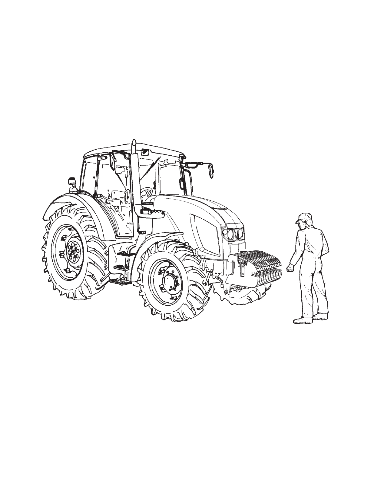
PREVENTIVE DAILY MAINTENANCE
Perform this maintenance daily or after every 8 - 10 hours of operation at the latest.
F11N004
24
PREVENTIVE DAILY MAINTENANCE
F11N005 XF_02_193 F_02_3a1
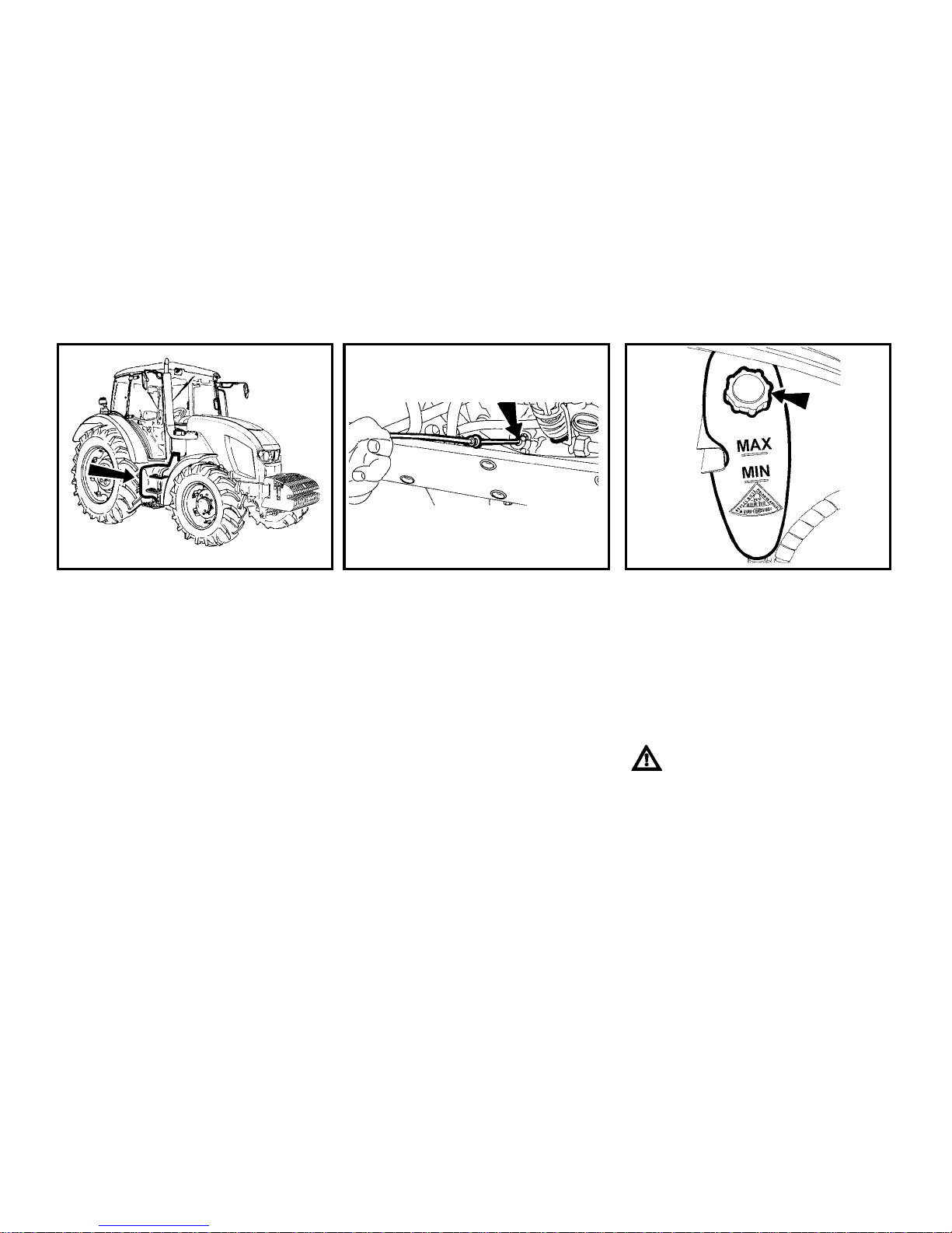
FUEL SYSTEM LEAKS
Check the fuel system for leaks,
including the fuel tank. Repair any leaks
immediately. The hole for draining dirt
from the fuel tank is found in its bottom.
ENGINE OIL LEVEL
After unscrewing and removing the oil
dip-stick check the oil quantity in the
engine and then check the connection of
the engine lubrication system for leaks.
Maintain the oil level between the dipstick marks.
COOLING SYSTEM
Check the connections of the engine
cooling system for leaks and the coolant
quantity in the expansion tank.
Replenish the missing quantity up to the
upper mark indicated MAX. The
minimum acceptable cooling liquid level
is indicated by the MIN mark.
Only release the overpressure
plug when the coolant has cooled
down! There is a danger of
scalding!
25
PREVENTIVE DAILY MAINTENANCE
FH12N017 FH12N064 F13
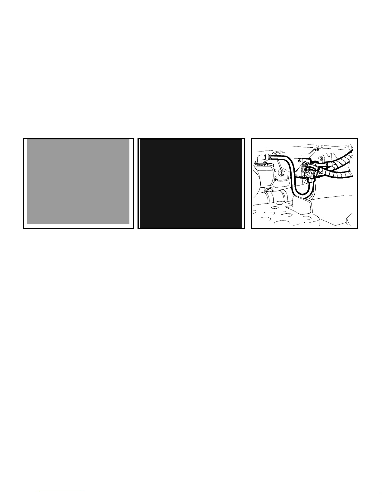
LIQUID BRAKES
Check the liquid brakes for leaks as well
as the liquid control of the clutch and the
braking liquid level in the expansion tank.
Maintain the brake liquid level in the
range of 3/4 of the tank content (max.
level) and 1/2 of the tank content
(minimum level).
TRAILER AIR BRAKES
Check the air system of the brakes for
leaks and the efficiency of the tractor
brakes with a trailer (see the
Maintenance instructions chapter; the
Checking the air systems for leaks
section of this Operator’s Manual).
TRAILER HYDRAULIC BRAKES
Check the hydraulic brakes of the trailer
for leaks.

26
PREVENTIVE DAILY MAINTENANCE
D402 F_02_6a F_02_9
HYDROSTATIC STEERING
- Check the oil level in the hydrostatic
steering tank.
- Check the tightening of screws and
nuts of the steering rods and levers.
- Check the condition of all the hoses of
the hydraulic steering circuit for
damage and for oil leaks.
AIR CLEANER
If the air cleaner is heavily clogged with
dirt, this condition is indicated by a
sensor that lights up an indicator on the
dashboard.
CAB FILTRATION
Check and if necessary clean the cab
ventilation air filters installed in the front
overhang of the roof.
The filter exchange interval depends on
the dustiness of the working
environment.
Partial regeneration can be performed by
beating out or blowing with compressed
air.
Do the cleaning or replacement of the
filter elements after removing the
covering grills in the roof overhang.

27
PREVENTIVE DAILY MAINTENANCE
F18 F_02_100 F11N006
HITCHES
Check the condition of the hitching and
attachment systems of the tractor and
trailer.
AFTER WIRK WITH FRONT
IMPLEMENTS AND IN CASE OF
COOLER CLOGGING
After work with front implements:
Check the connections of the external
hydraulic circuit of the control of the
front three-point hitch for leaks
Clogging of the coolers:
Remove the side plate of the hood.
Release and slide the cooler to the left
side of the tractor.
Clean the front walls of the engine
(gearbox, air-conditioning condenser)
cooler with compressed air (blow air in
the direction from the engine).
Remove residual dirt from the space
under the hood so that it should not be
suctioned again.
TYRES AND WHEELS
Check the air pressure in the front and
rear tyres. Depending on the character
of work adjust the pressure to the
recommended value. Check and if
necessary retighten the bolts of the front
and rear wheels (the rim / disc and disc /
wheel shaft connection).
Never drive with loose wheel
bolts!

28
PREVENTIVE DAILY MAINTENANCE
FH12N014
SHORT FUNCTIONAL TEST
After starting the engine check whether
the hydrostatic steering failure, engine
lubrication and charging indicators have
gone off.
Verify the function of the hydraulic
steering circuits and check them for
leaks.

29
ACQUAINTANCE WITH THE TRACTOR
The tractor user is obliged to get
acquainted with the recommended procedures and instructions
for safe operation of the tractor in
advance. It is too late to do so
during operation!
Page
Safety cabin .............................................................................................................. 31
Opening the door from the outside ............................................................................ 31
Opening the door from the inside .............................................................................. 31
Rear window .............................................................................................................. 32
Side window .............................................................................................................. 32
Windshield washer nozzle ......................................................................................... 33
Windshield washer tank ............................................................................................ 33
Windshield washer engagement ............................................................................... 33
Passenger´s seat ...................................................................................................... 34
Shelf and toolbox ...................................................................................................... 35
Rear view mirrors ...................................................................................................... 35
Driver´s seat .............................................................................................................. 36
Tilting and protrusion of steering wheel ..................................................................... 36
*Air filter with active carbon ....................................................................................... 37
Heating control panel, air-condition ........................................................................ 38
Heating valve control (A) ........................................................................................... 38
Ventilator control (B) ................................................................................................. 38
Switch air-condition (C) .......................................................................................... 38
Air circu l a tion i n cabin c ontro l ( D) ................................................................................. 39
Proper function of the heating and air-condition system ................................................ 39
Fast heating of the cabin area ..................................................................................... 39
Fast cooling of the space of the cabin ................................................................. 40
Operation of heating or air-condition with tractor´s work ........................................... 40
Immediately after cooling the cabin ........................................................................... 40
Air-condition and heating registers (A) ...................................................................... 41
Front windshield (B) defrosting .................................................................................. 41
Sun screen ................................................................................................................ 42
Internal lighting .......................................................................................................... 42
Dashboard ................................................................................................................. 45
Display description .................................................................................................... 46
Change of the look of display .................................................................................... 46
Display – change of display ....................................................................................... 47
Display – Resetting data ........................................................................................... 47
Display – manual brake ............................................................................................. 48
Display - error messages .......................................................................................... 48
Display – service menu ............................................................................................. 49

30
ACQUAINTANCE WITH THE TRACTOR
Display – setting language mutation ......................................................................... 49
Switches and levers .................................................................................................. 50
Lights switch ............................................................................................................. 51
Front drive axle button .............................................................................................. 51
Switch of warning lights ............................................................................................. 51
Lights switch between the grill and the cabin ............................................................ 52
Rear differential lock button ...................................................................................... 52
Preselection of torque multiplier switch ..................................................................... 52
Direction lights, Lower beam head lights, head lights and horn switches ................. 53
Switch box ................................................................................................................. 53
Key in “0” position ..................................................................................................... 54
Key in “I” position ...................................................................................................... 54
Key in “II” position ..................................................................................................... 54
Ignitor and three-pin socket ....................................................................................... 55
Manual throttle .......................................................................................................... 55
Reversing lever ......................................................................................................... 56
Gear shifting lever ..................................................................................................... 56
Gear shifting scheme ................................................................................................ 56
Pedals and levers ..................................................................................................... 57
Road and reduced speeds shifting lever ................................................................... 57
PTO revolutions preselection lever ........................................................................... 58
Manual brake lever and coupling for semi-trailer control lever .................................. 58
Hydraulic control panel .............................................................................................. 58
Auxiliary hydraulic switchbox control (external hydraulic circuit) .................................... 59
Control panel on the right column of the cabin .......................................................... 59
Battery disconnector ................................................................................................. 59
Fuel tank ................................................................................................................... 60
Fuel tank drain plug .................................................................................................. 60
Aggregation opening ................................................................................................. 60

31
ACQUAINTANCE WITH THE TRACTOR
F11N039 F_02_11 F23
SAFETY CABIN
Use the left side of the tractor for
getting on and getting off the tractor.
Use three-stage climbing irons
and hold the bars when getting
on and getting off the tractor.
Pay increased attention in the area of gear shifting lever and
manual throttle lever.
Safety cabin is equipped with toned
glass.
OPENING THE DOOR FROM THE
OUTSIDE
Door can be opened from the outside by
pressing a button. Left door can be
locked.
OPENING THE DOOR FROM THE
INSIDE
1. Lever for opening the door from the
inside
2. Lever for opening the door from the
inside
The door is held by a gas strut with a full
opening.
Driving with open door is not recommended for their possible damage.

32
ACQUAINTANCE WITH THE TRACTOR
F24 F25
REAR WINDOW
Is equipped with a handle and in an open
position is locked by gas spruts. Rear
window is heated.
When driving on an uneven surface we recommend to secure
the window in a closed position danger of window cracking. Before starting the work with the machinery Before
starting the work with mounted in threepoint hitch of the tractor, make sure that
there is not a danger of collision between
the mounted tools with maximum lifting
of rear three-point hitch and open rear
window. In case of collision we recommend to work with a closed window.
SIDE WINDOW
Secured by plastic handle in half open
position.

33
ACQUAINTANCE WITH THE TRACTOR
F28 F_02_152a F_02_137
WINDSHIELD WASHER NOZZLE
Nozzle is adjustable with a needle of a
maximum strength of max. of 0.8 mm.
WINDSHIELD WASHER TANK
Windshield washer tank is placed on the
rear wall of the cabin from the outside
side.
WINDSHIELD WASHER
ENGAGEMENT
Windshield washer is set in activity by
pressing a switch of front double-gear
windshield washer placed on the right
column of the cabin. The maximum
length of uninterrupted pump run of
windshield washer is 20 s.

34
ACQUAINTANCE WITH THE TRACTOR
FH12N020.tif
PASSENGER´S SEAT
Passenger´s seat is tiltable and placed on the left mudguard of the cabin.
SEAT TILTING OUT
Passenger´s seat to be tilted out in the direction of an arrow (1) upward. Locking of the seat is done automatically
SEAT TILTING
Lift the passenger´s seat in the direction of an arrow (2), pull the lever (3) to the direction of the driver´s seat, tilt the seat in the direction of an arrow (4).

35
ACQUAINTANCE WITH THE TRACTOR
F31 FH12N025 F_02_12
SHELF AND TOOLBOX
Shelf is placed on the left side of driver´s seat.
Toolbox is placed in the rear part of the cabin behind the driver´s seat.
Another shelf is placed on the right mudguard.
REAR VIEW MIRRORS
Before the drive or starting the work, adjust rear view mirrors so that they enable
to monitor the whole drive way or working field.

36
ACQUAINTANCE WITH THE TRACTOR
FH12N026
DRIVER´S SEAT
1- The control of setting the seat suspension according to the driver´s
weight (setting by rotation, in the direction according to pictogram on
the boot of the seat)
2- Longitudinal setting of the seat lever
3- Seat vibrations absorption control (by tilt over of the control forward,
floating position of the seat is engaged)
4- Setting the angle of rest control
5- Tilting elbow rest
6- Pneumatic suspension of seat setting control (by pulling in the direction
upward, the rigidity of the suspension increases, by pulling in downward
direction, it decreases)
DRIVER´S SEAT WITH MECHANICAL SUSPENSION
Control according to points 1, 2, 3, 4 and 5
Point 2, lever is placed on the right
DRIVER´S SEAT WITH PNEUMATIC SUSPENSION
Control according to points 2, 3, 4, 5 and 6
Point 2, lever is placed on the left
TILTING AND PROTRUSION OF STEERING
WHEEL
Tilting column of steering wheel enables variable
setting of position of the steering wheel both in
terms of angle and height.
Height setting of steering wheel
The setting is done by protrusion or retracting the
steering wheel after unlocking arrestment by turning a lever (1) in the direction of an arrow. After
setting the steering wheel, lock the lever (1) by
tightening in the direction of an arrow.
Angle setting of steering wheel
Setting is done by tilting the steering wheel after
unlocking the lock by turning the lever (2) in the direction of the arrow. After setting the steering
wheel, secure the lever (2) by retightening against
the direction of the arrow.

37
ACQUAINTANCE WITH THE TRACTOR
F13BN015
*AIR FILTER WITH ACTIVE CARBON
Active carbon filters are installed in the placed of standard dust filter and the replacement is done in the same way as with standard filters. Filter must be inserted
with the white side to the grid. Assembly instructions are found in the chapter
“Maintenance instructions”.
Filter is used only when spraying pesticides, then it must be replaced back by a paper
filter because the flying dust would clog the carbon filter very fast.
The recirculation control must be in the position “air is sucked from the outside”
Ventilator control must be in the position “maximum ventilator run”
WARNING: filter does not provide full protection against toxic substances
Wear protective gloves when manipulating with the filter
Do not clean the filter and do not blow through with compressed air
DANGER: Replace the active carbon filter every 200 hours or 36 months (date
of production is given on the filter). If you happen to smell pesticides in the
cabin, replace the filter immediately and have the sealing of the cabin
checked. Used filters must be damaged in specialized collection centres
When spraying pesticides and
using heating filters with active
carbon, the recirculation control
must be in the position of „air
sucked from the outside” and the
ventilator control “maximum ventilator run” for creating surplus
pressure in the cabin

38
ACQUAINTANCE WITH THE TRACTOR
F13BN009 F_02_16 F_02_17a
HEATING CONTROL PANEL, AIRCONDITION
A - heating valve control
B - ventilator control
C - air-condition switch
D - air circulation in the air of cabin lever
HEATING VALVE CONTROL (A)
a - heating valve closed
b - heating valve opened
VENTILATOR CONTROL (B)
1 - ventilator off
2 - slowly run of ventilator
3 - medium run of ventilator
4 - maximum run of ventilator
SWITCH AIR-CONDITION (C)
Do engagement and disengagement of
air-condition system function by switching the switch with a symbol of snow
flake (C).
You will set the air-condition system going by pressing the switch (the symbol of
snow flake lights up).
You will disengage the air-condition system by repeated press of switch (snow
flake symbol switches off).

39
ACQUAINTANCE WITH THE TRACTOR
F_02_17b F11009 F_02_18a
AIR CIRCULATION IN CA BIN
CONTROL(D)
a - surrounding (outside) air is sucked in
through filters to cabin – sucking the
air from cabin is closed.
b - Air is sucked in from the space of the
cabin and again blown off to the cabin
(inner air recirculation for fast adjustment of temperature in the cabin)
The intake of air from the outside
of the cabin is completely locked
and there is no surplus pressure
in the cabin which would prevent
pervasion of unfiltered air to the
cabin!
Do not use this position of the
control with work of the tractor!
PROPER FUNCTION OF THE HEATING
AND AIR-CONDITION SYSTEM
It is necessary to create surplus pressure
in the cabin for proper function of the
heating or air-condition. We therefore
recommend you to close all the windows
and doors and tilting cover of the cabin.
FAST HEATING OF THE CA BIN AREA
Proceed accordingly:
1 - Turn the heating valve control (A) to
the position on the right (fully opened
heating valve).
2 - Set air circulation in cabin control (D)
to the position of inner circulation.
3 - Select applicable gear of the ventilator
run (position 1, 2, 3) by ventilator control (B).
4 - Set the expiration under the requested
angle to avoid direct fanning of the
people in the cabin.
5 - After heating the space of the cabin,
set the air circulation in the cabin control (D) to the position of sucking the
outer air - see fig. F_02_17b position
(a)

40
ACQUAINTANCE WITH THE TRACTOR
F_02_18 F_02_19 F_02_20
FAST COOLING OF THE SPACE OF
THE CABIN
Proceed accordingly:
1 - Switch the heating valve control lever
(A) to the position to the left
2 - Set the air circulation in the cabin lev-
er (D) to the position of outer air sucking
3 - Select an applicable gear of the venti-
lator run (position 1, 2, 3) by ventilator control (B)
4 - Switch the air-condition system by a
switch (C)
5 - Set expiration under the requested
angle so that direct fanning of people
in the cabin does not occur (the possibility of illness due to intensive cooling of parts of body).
OPERATION OF HEATING OR AIRCONDITION WITH TRACTOR´S WORK
With engaged inner recirculation of air is
the inflow of fresh air closed and there is
foul air in the space of the cabin by operator. This state can cause the feeling of
fatigue and there can also be penetration
of dust to the cabin because of the loss
of surplus pressure.
Note: Set the control (D) according to individual requirements on temperature to
the position between (a) and (b) so that
the ventilator sucks the air from the outside of the cabin through filters, when
working.
IMMEDIATELY AFTER COOLING THE
CABIN
Immediately after cooling the cabin and
lowering the inner temperature on the
required values, we recommend the following:
Do the continuous regulation of the air
temperature with air condition on by
opening the heating valve (A). The air
entering the cabin from expiration is
not so intensively dried with this setting.
Continuous temperature control with
air-condition on can be also done by
lowering the output of ventilator by
switching the control (B) to position 1
or 2.

41
ACQUAINTANCE WITH THE TRACTOR
F13BN010 F13BN011
AIR-CONDITION AND HEATING REGISTERS (A)
Positionable heating and air-condition registers, front (A), rear (B).
FRONT WINDSHIELD (B)
DEFROSTING
To ensure quick defrosting of the front
windshield direct the central heating outlets (1) under the angle of approx. 45°
towards the windshield. Direct the side
outlets (2) under the angle of approx. 45°
to the cab corners.
After defrosting of the front windshield direct the side outlets to the side glasses
of the doors as necessary and gradually
defrost them. After defrosting direct the
outlets in such a way that the air should
not be blown directly to the driver, but
down to the driver’s legs.

42
ACQUAINTANCE WITH THE TRACTOR
FH13N009 F13BN014
SUN SCREEN
You can draw out the sun shield by pulling the handle in the direction of the arrow. The shield gets back to initial position after pressing the button (1) by an
applicable shield.
INTERNAL LIGHTING
To be turned on and off by means of a
button marked with the arrow.

43
NOTES

44
ACQUAINTANCE WITH THE TRACTOR
FH12N010

45
ACQUAINTANCE WITH THE TRACTOR
DASHBOARD
DESCRIPTION
A - controls
B - coolant thermometer
C - fuel gauge
D - pressure gauge
E - speedometer
F - display
CONTROLS AND BUTTONS
When switching the key in switchbox
from “0” position to “1” position, all controls light up.
1 - High beam lights (blue). Lights up
with high beam lights on.
2 - Tractor turn signal indicator (green).
3 - Turn indicator control of 1
st
trailer
(green).
4 - Turn indicator control of 2
nd
trailer
(green).
5 - Minimum air pressure in brake sys-
tem control (red). It is lit up with the
pressured drop for air brakes of trailer under the critical interval i.e. 450
kPa.
6 - Manual brake (red). It is lit with en-
gaged manual brake.
7 - Charging (red). With engine run,
lights up with charging disorder. If the
engine is at standstill, it must be lit.
8 - Lubricating (red). With engine running
lights up with the oil pressure drop
under 120 to 60 kPa. If the engine is
at standstill, it must be lit up
9 - Air cleaner clogging (yellow). Lights
up with air filter clogging.
10 - (not connected).
11 - (not connected)
12 - (not connected)
13 - Indicator (red) of a failure in the hy-
drostatic control system. It lights with
engine operation in hydrostatic control
failure. If the engine is at standstill, it
must be lit up.
14 - (not connected)
15 - Diesel particle filter control
(red), for more see “Driving
operation”
16 - Diesel particle filter control
(green) , for more see chapter „Driving
operation“
17 - Engine ignition (yellow). Signalizes
the activity of device for easement of
the start of the engine
18 - (not connected)
19 - Fuel (orange). It lights up with the
remaining 1/6 - 1/10 of the volume of
the tank.
20 - Gearbox disorder control (red), for
more see “Driving operation” chapter
21 - Gear box oil filling overheating con-
trol (red), for more see chapter “Driving operation”
22 - Gearbox switchboard delivery filter
clogging control (red), see “Driving
operation” chapter for more infor-
mation
23 - Rolling up in the menu button
24 - Rolling down in the menu button
25 - entry to the menu button, confirming
items on the menu
26 - LCD backlight inversion button
27 - Reset button hours of operation and
km
28 - Change of display button (road,
PTO, Moto hours, km).

46
ACQUAINTANCE WITH THE TRACTOR
FH13N001 FH12N036
DISPLAY DESCRIPTION
The following values are displayed on the display:
1 - shifted gear of multiplier of torque, according to shifted gear L, M or H is displayed
2 - switching the switch of torque multiplier preselection
3 - switching the function of rear PTO shaft automatic disengagement
4 - gear shifting lever position, reversing F driving forward, N neutral, R reversing
5 - road and reduced speeds shifting lever position, Lo reduced speeds, Hi neutral or
road speeds
6 - main depicting field
7 - secondary displaying field
8 - engagement of front axle drive switch
9 - dashboard network overcharge signalization
10 - engagement of rear differential lock
CHANGE OF THE LOOK OF DISPLAY
The change of look of display from display (1) to display (2) can be done by
pressing a button (A).

47
ACQUAINTANCE WITH THE TRACTOR
FH12N033 FH12N035
DISPLAY – CHANGE OF DISPLAY
By repeated pressing of button (A), you can click between individual displays of data
on display:
1 - Main field travel speed of tractor pole, secondary field of PTO shaft revolution, if it
is on
2 - Main field of PTO shaft revolution if it is on, secondary field of travel speed of trac-
tor
3 - Automatic disengagement of rear PTO shaft, more in the chapter “Drive of agricul-
tural machinery”
4 - Main field of number of hours in operation in total, secondary field of hours in op-
eration from the last resetting of the data
5 - Main field of the number of kilometres in operation in total, secondary field number
of kilometres in operation from the last resetting of the data
6 - Accumulator battery voltage
DISPLAY – RESETTING DATA
Resetting data marked with an arrow can
be done on a display (4) and (5)
Select display (3) or (4) with a button (A)
and by a longer pressing of button (B)
reset data marked with an arrow.

48
ACQUAINTANCE WITH THE TRACTOR
FH12N039 FH12N041
DISPLAY – MANUAL BRAKE
If the tractor is not braked by a manual
brake, a warning is displayed on a display (letter P in a circle) and at the same
time a sound signal is heard.
See the chapter “Driving operation” for
more
Brake the tractor by a manual
brake.
DISPLAY - ERROR MESSAGES
Serious faults in the system (1)
STOP sign, number of fault (1) is displayed on a display with serious faults.
If this situation occurs, set the tractor aside and contact service
Less serious faults in the system (2) a (3)
With less serious faults in the system, the number of faults (2) are displayed on the
display for a time period of approximately 5 seconds.
Then the display of fault is minimized to the main field. (3)
If this situation occurs, complete the work and contact service.
See more in the chapter of “Driving operation”.

49
ACQUAINTANCE WITH THE TRACTOR
FH12N063 FH12N067
DISPLAY – SERVICE MENU
Service menu serves for the maintenance of the tractor by an authorized
service and the setting of language for
display of dashboard.
Entry to service menu
You will enter the service menu by a
longer pressing of (A) button.
The selection of items to be done by (B)
and (C) buttons. The selected item is
marked by an arrow (1).
Exit from service menu
By buttons (B) and (C), select an item
EXIT and press (A) button.
DISPLAY – SETTING LANGUAGE
MUTATION
Enter the service menu
Select the item LANGUAGE by (B) and
(C) buttons and press button (A).
Select language mutation by buttons (B)
an (C) and by one by one presses of button (A) available language mutations will
be one by one displayed. When achieving the desired language mutation, leave
the service menu.
Dashboard is switched to a selected language mutation.

50
ACQUAINTANCE WITH THE TRACTOR
F13HBN001
SWITCHES AND LEVERS
a - Lights switch (off, parking, head)
b - Lower beam lights in the grill of the tractor
and working lights in the cabin of the tractor
switch
c - Fog light switch (off - on). Fog light function
is signalized by a lit symbol on the switch.
d - Working lamp switch (off - on). Working
lamp function is signalized by a lit symbol
on a switch.
e - Warning lights switch
f - Front drive axle button. Engaged front
drive axle is signalized by lit symbol on a
switch.
g - Beacon switch (off - on)
h - Working lights in the grill of the bonnet
switch (off - on)
i - Preselection of torque multiplier switch
j - Differential lock button
k - Switch box
l - Direction lights, lower beam head lights,
head lights and horn switches acoustic and
light
m - Reversing lever (forward, neutral, back-
ward)

51
ACQUAINTANCE WITH THE TRACTOR
F56 FH12N031 F58
LIGHTS SWITCH
a - illumination off
b - side and end point lights on, illumi-
nation of licence label, illuminated
c - all devices on in “b” position. Lower
beam head lights or head beam
lights are engaged (according to the
position of direction lights, lights and
horn switches).
FRONT DRIVE AXLE BUTTON
Use the front drive axle with slipping of the rear wheels to enhance the draught of the tractor.
The engagement of front drive axle is
signalized by a lit symbol on the switch
and a symbol on the display.
For more information see chapter Driving
operation
SWITCH OF WARNING LIGHTS
a - warning lights on
b - warning lights off
Function of warning lights is signalized
by interrupted blinking control on the
dashboard.

52
ACQUAINTANCE WITH THE TRACTOR
F59 FH12N032 D102
LIGHTS SWITCH BETWEEN THE
GRILL AND THE CABIN
a - roof lights on
b - roof lights off
The switch controls the illumination in the
grill or in the roof of the cabin of the tractor. Use the lights in the roof of the cabin
only when tools covering headlights in
the grill is attached in front three-point
hitch. A lit symbol on the switch signalizes light on in the roof.
Headlights can be lit only in the grill of
the bonnet.
REAR DIFFERENTIAL LOCK BUTTON
Engagement and disengagement of rear
differential lock is done by pressing the
button which returns to its original position after release.
The engagement of lock differential is
signalized by a lit symbol on the button
and a symbol on the display.
For more see the chapter “Driving operation”.
PRESELECTION OF TORQUE
MULTIPLIER SWITCH
a - Preselection switch off
b - Preselection switch on
The position (b) of preselection switch on
is signalized by a lit symbol on a switch
and a ymbol on the display
For more see the chapter “Driving operation”

53
ACQUAINTANCE WITH THE TRACTOR
X139 F13BN004
DIRECTION LIGHTS, LOWER BEAM
HEAD LIGHTS, HEAD LIGHTS AND
HORN SWITCHES
a - Acoustic horn – press the switch in
the direction of an axis
b - Lower beam head lights
c - Direction lights to the right
d - Direction lights to the left
e - Acoustic horn
f - Lower beam headlights
SWITCH BOX
Switchbox is placed on the dashboard, see
arrow.

54
ACQUAINTANCE WITH THE TRACTOR
S43 S44 S45
KEY IN “0” POSITION
The voltage of all key operated devices
is disconnected. The key can be removed.
KEY IN “I” POSITION
Voltage is connected to all devices with
the exception of the starter. The key is in
this position with engine running.
KEY IN “II” POSITION
Starter and feeding of all devices is engaged in this position with the exception
of windshield wiper, windshield washer,
cabin ventilator and air-condition. After
starting, the key automatically returns
back to “I” position.

55
ACQUAINTANCE WITH THE TRACTOR
FH12N028 F13BN005
IGNITOR AND THREE-PIN SOCKET
Ignitor (1) and a three-pin socket (2) are
placed on the panel of right rear
mudguard.
MANUAL THROTTLE
A - maximum supply
B - idle run

56
ACQUAINTANCE WITH THE TRACTOR
X212a FH12N037 FH12N038
REVERSING LEVER
F – front driving; lever in the front
N - neutral
R – back driving; lever at the back
GEAR SHIFTING LEVER
- main gear shifting lever
1. button for disengaging clutch on the
head of gear shifting
2. buttons of shifting individual gears of
multiplier
GEAR SHIFTING SCHEME
Reversing speeds can be shifted only by
means of reversing lever. The scheme is
placed on the head of gear shifting lever.

57
ACQUAINTANCE WITH THE TRACTOR
F13BN008 F72
PEDALS AND LEVERS
1 - travel clutch pedal
2 - foot brake pedals joint by a catch
3 - throttle pedal
ROAD AND REDUCED SPEEDS
SHIFTING LEVER
The lever is placed on the right side of
driver´s seat.
H -
Road speeds
N -
Neutral
L -
Reduced speeds

58
ACQUAINTANCE WITH THE TRACTOR
FH13N008 F74 XF_02_213
PTO REVOLUTIONS PRESELECTION
LEVER
The lever (1) is placed on the right side
of driver’s seat.
For more information see the chapter on
Drive of agricultural machines.
MANUAL BRAKE LEVER AND
COUPLING FOR SEMI-TRAILER
CONTROL LEVER
1 - manual brake lever
a - unbraked
b - braked
2 - coupling for semi-trailer lever
a - transporting position
b - Bearing hooks folded up; tow
hook with carrier can be started
HYDRAULIC CONTROL PANEL
It is placed in the area of right mudguard.
A detailed description of controls and function follows in chapters “Hydraulic equipment” and “Electrohydraulics” of this instructions manual.

59
ACQUAINTANCE WITH THE TRACTOR
FH12N040 FH13N011 FH12N022
AUXILIARY HYDRAULIC SWITCHBOX
CONTROL (EXTERNAL HYDRAULIC
CIRCUIT)
Is placed in the upper part of right mudguard.
A detailed description of control and
function of integrated hydraulic switchboard (of external hydraulic circuit) follows in “Hydraulic equipment” chapter of
this instructions manual.
CONTROL PANEL ON THE RIGHT
COLUMN OF THE CABIN
1 - rear PTO shaft engagement
2 - front PTO shaft engagement
3 - two-position switch of front wiper and
front windshield washer control
4 - rear wiper switch
5 - switch of front working lights on the
roof of the cabin
6 - switch of rear working lights on the
roof of the cabin
7 - rear mirrors heating *switch
8 - rear window heating *switch
9 - rear PTO shaft start rate. Three levels
can be selected according to connect-
ed tools:
10 - rear PTO shaft revolutions switch
(540 or 540E/1000)
BATTERY DISCONNECTOR
Disconnect the battery immediately by battery disconnector which is
placed on the right side of the
tractor with long-term standstill,
repairs or accident.
a - battery connected
b - battery disconnected

60
ACQUAINTANCE WITH THE TRACTOR
F_02_22
FUEL TANK
A plastic tank of 240 litres volume is
mounted as a standard for all types of
tractors.
Do not step on the fuel tank!
FUEL TANK DRAIN PLUG
Plug for draining dirt and fuel off the fuel
tank is in its bottom.
AGGREGATION OPENING
Aggregation opening serves for cabelling
or Bowden control of aggregated tools
placement.
Pull to protrude the part of sealing of rear
window in upward direction. Put the aggregated tool control through the originated hole.
Insert cabelling or Bowden controls to
the holes of passage of aggregation
opening. Return the sealing of the rear
window to its original position by exercising pressure

61
DRIVING OPERATION
Before riding with a new tractor,
first get acquainted with the gear
shifting scheme and try the individual positions of gear shifting
lever out with engine at standstill.
Also make sure that the technical
condition corresponds to the conditions of safe operation.
Page
Before you start ......................................................................................................... 63
If you do not succeed in starting the engine .............................................................. 63
Non-permitted starting ............................................................................................... 63
Starting the engine of the tractor ............................................................................... 64
Ignition system disorders signalization ...................................................................... 64
Coolant heater ........................................................................................................ 65
Starting the engine with the use of coolant heater ..................................................... 65
Immediately after start ............................................................................................... 66
Engine heating .......................................................................................................... 66
Gear shifting .............................................................................................................. 67
Reversing lever ......................................................................................................... 67
Reversing lever position signalization ....................................................................... 67
Shifting road and reduced speeds ............................................................................. 68
Road and reducing speeds lever position signalization ............................................. 68
Driver´s seat - safety switch ...................................................................................... 68
The principles of appropriate use of tractors ............................................................. 69
The description of the system of travel clutches ........................................................ 69
The way of controlling the travel clutch by ................................................................. 69
The differences in ways of controlling the travel clutch by ......................................... 69
Interrupted sound signal ............................................................................................ 71
Dead start of the tractor ............................................................................................ 72
Dead start of tractor in regular operation - automatic dead start function .................. 72
Dead start by means of automatic dead start function .............................................. 72
Dead start of tractor in regular operation – clutch pedal ............................................ 73
Dead start - using the clutch pedal ............................................................................ 73
Change the direction of drive .................................................................................... 74
Change the direction of drive by means of reversing lever ........................................ 74
Change the direction of drive - using the clutch pedal ............................................... 75
Gear shifting .............................................................................................................. 75
Gear shifting - using the clutch pedal ........................................................................ 75
Gear shifting - using the clutch control button on the head of gear shifting lever ...... 75
Signalization of travel clutches and gear box system failures .................................... 76

62
DRIVING OPERATION
Serious failures of travel clutches and reversing levers system ..................... 77
Less serious failures of travel clutches and reversing system ........................ 77
Blocking the automatic dead start function ..................................................... 77
Three-gear torque multiplier ........................................................................... 78
Signalization of multiplier function .................................................................. 78
Increasing, decreasing the travel speed by two gears ....................................... 78
Multiplier preselection switch ......................................................................... 79
Multiplier pre-selection signalization ............................................................... 79
Automatic multiplier shifting ........................................................................... 80
Front drive axle control................................................................................... 83
Automatic disconnection of front drive axle .................................................... 83
Drive with front drive axle on .......................................................................... 84
Rear differential lock button ........................................................................... 84
Diesel particle filter ......................................................................................... 85
Diesel particle filter – system failures signalization ........................................ 86
Diesel particle filter failure codes ................................................................... 86
Diesel particle filter regeneration .................................................................... 87
Manual brake - signalization .......................................................................... 88
Driving up the slope ....................................................................................... 89
Driving down the slope ................................................................................... 89
Foot brakes .................................................................................................... 89
Air brakes of trailers and articulated trailers ................................................... 90
Warning signalization of air pressured drop ................................................... 90
One-hose and two-hose brakes ..................................................................... 91
One-hose brakes ........................................................................................... 91
Two-hose brakes ........................................................................................... 91
Hydraulic brakes of trailers ............................................................................. 92
Connecting and disconnecting quick couplings of trailer hydraulic brakes ..... 92
Stopping the tractor – manual brake .............................................................. 93
Stopping the engine ....................................................................................... 93
Leaving the tractor ......................................................................................... 93
Warning s i gnali z ation o f hydrostat i c s teeri n g fail u re .......................................... 94

63
DRIVING OPERATION
FH12N053 F11N012 F11N013
BEFORE YOU START
Before you start the engine, make
sure that:
1. the tractor is properly braked.
2. the main gear shifting lever of
gears in neutral position.
3. Reversing lever is in neutral
position
4. PTO switches on the right column of the cabin are off
If clutch pedal is not depressed
the tractor cannot be started –
start protection switch is not
switched
IF YOU DO NOT SUCCEED IN
STARTING THE ENGINE
Return the key to "0" position. Wait 30
second and repeat the start.
Never help the stopping engine
by a starter. You are being exposed to the danger of starter
damage.
NON-PERMITTED STARTING
It is forbidden to start the tractor
by short-circuiting the starter
clamps. Start only from the driver´s seat.
It is necessary to disconnect minus
pole of accumulator and all the
shifting levers including PTO shaft
shifting lever to be shifted in neutral position with any manipulation
or repair of the starter. The starter´s clams are covered with a cap.

64
DRIVING OPERATION
FH12N051 FH112N052 F_02_176a
STARTING THE ENGINE OF THE
TRACTOR
As a standard, the tractors are equipped
by glow plugs in the heads of rollers.
When starting the engine, it is
necessary to sit on the driver´s
seat.
1. Insert the key to the switchbox (“0”
position).
2. Depress the clutch pedal.
3. Shift the main gear shifting lever to
neutral position.
4. Shift the reversing lever to neutral position.
5. Make sure that all PTO switches on
the right column of the cabin are
switched off.
6. Turn the key to “I” position. A yellow
control will light up on the dashboard
signalising the proper igniting function.
7. Wait for the ignition control to turn off
(the time is dependent on the temperature of the coolant).
If the ignition control merely
blinks instead of lighting up, there
is a disorder in the ignition system (see ch.: Ignition system disorder signalization). The signalised fault must be resolved in an
expert service garage.
8. Turn the key to the “II” position (start).
9. After starting the engine, release the
key immediately. Do not start for more
than 15 sec.
IGNITION SYSTEM DISORDERS
SIGNALIZATION
Ignition system disorders are signalized
by blinking of ignition control.
- If ignition control blinks at standstill
once per second, ignition in emergency system occurs just like at low temperatures regardless of the temperature of coolant.
- If the ignition control blinks at standstill
twice per second, the ignition is put off
operation (does not work).
- If the ignition control blinks permanently
during the run of engine, there is a disorder of ignition control and ignition has
not been completed. The disorder must
be forthwith removed, because there is
the danger of battery depletion.

65
DRIVING OPERATION
F11N016 F91
COOLANT HEATER
Coolant heater is mounted on the engine
block.
The heater has the output of 1000 W
with voltage of 220 V of electric alternate
current.
STARTING THE ENGINE WITH THE USE OF COOLANT HEATER
Heating the coolant makes starting the engine easier with low temperatures. Inlet
electric installation and its protection against dangerous touch must be done in accordance with valid regulations.
1. Insert the plug to the heater first.
2. Then connect the heater to the electric network of the voltage of 220 V.
With regard for the lower engine wear when starting at low temperatures, the use of
heater is recommended by the manufacturer. The duration of heating is dependent
on the surrounding temperature (1 - 2 hours before scheduled start should suffice).
After completing the heating, first disconnect the device from the electric network and only then pull the plug out of the heater!
The danger of injury by electric current!
It is necessary to ensure instruction of the tractor´s operator and regular revision of the heater of coolant including in let cable in the sense of
valid standards of the state in which the tractor is operated at least before every winter season.

66
DRIVING OPERATION
FH11N092 FH11N091
IMMEDIATELY AFTER START
After start, set the revolutions for
800 - 1000 revolutions per minute, allow the engine to run for a
time period of approximately 2
minutes.
In this time, do the control of greasing,
recharging, hydrostatic steering (the controls must turn off) and other functions
ensuring proper run of engine. The time
of engine operation without load must be
kept, in particular in winter season.
ENGINE HEATING
Do further heating of the engine during the drive. The heating of the engine by
lengthy idle run or sharp increase in revolutions is harmful to the engine.
If the temperature of coolant has not reached 45°C, do not exceed the engine
revolutions over 2000 rpm.

67
DRIVING OPERATION
FH12N037 X212a FH12N050
GEAR SHIFTING
The tractors are equipped with a fivegear synchronized gearbox, three-gear
torque multiplier, reversing and two-gear
reduction.
Five-gear gearbox is shifted by main
shifting lever with buttons for disengaging the travel clutch (1) and for shifting
the individual gears of multiplier (2).
REVERSING LEVER
The selection of the direction of travel
drive is done by reversing lever (forward,
backward).
F - driving forward
N - neutral
R - driving backward
The lever also serves for starting the
tractor without the depressed clutch pedal.
REVERSING LEVER POSITION
SIGNALIZATION
The individual positions of reversing lever are signalized by a sign (1) in the top
right corner of the display.
driving forward
Neutral
driving backward

68
DRIVING OPERATION
F96 FH12N057 FH12N069
SHIFTING ROAD AND REDUCED
SPEEDS
H -
Road speeds
N -
Neutral
L -
Reduced speeds
Shifting the gears of the main gearbox
with reduced speeds is the same as with
road speeds.
Road and reduced speeds shifting lever can be shifted only with
a tractor at standstill.
ROAD AND REDUCING SPEEDS
LEVER POSITION SIGNALIZATION
The individual positions of road and reduced speeds lever are signalized by a
sign (1) in the left bottom corner of the
display.
Hi -
road speeds
Hi -
neutral position
Lo -
reduced speeds
DRIVER´S SEAT – SAFETY SWITCH
The driver´s seat is equipped with a safety switch which signalizes the system of
driver abandoning the driver´s seat.
If the tractor is started, there is nobody
on the driver´s seat and reversing lever
under the steering wheel is shifted to F
or R position, N position is shifted automatically and tractor does not start.
If this situation occurs, it is necessary to
sit on the driver´s seat, to return the reversing lever under the steering wheel to
N position and then to select the direction of drive again (F or R).

69
DRIVING OPERATION
THE PRINCIPLES OF APPROPRIATE USE OF TRACTORS
The listed principles for tractor´s operation serve for facilitating the operation and
guarantee corresponding service life of travel clutch!
THE DESCRIPTION OF THE SYSTEM OF TRAVEL CLUTCHES
The tractor is equipped with two individual travel clutches, one for travelling forward and one for travelling backward.
The selection of the driving direction and also the choice of a specific travel clutch is done by shifting the reversing lever under the
steering wheel from neutral position to the position forward or backward.
THE WAY OF CONTROLLING THE TRAVEL CLUTCH BY
1 - Reversing lever
2 - Clutch control button on the head of reversing lever
3 - Clutch pedal
THE DIFFERENCES IN WAYS OF CONTROLLING THE TRAVEL CLUTCH BY
1 - Reversing lever
This way of control has automatic start function.
When shifting the reversing lever to neutral position, there is release of travel clutch
When shifting the reversing lever to the forward or backward position, there is a switch of travel clutch and subsequent smooth
dead start of the tractor in the direction defined by reversing lever.
The speed of switch of travel clutch and the smoothness of dead start is controlled by a controlling unit on the basis of
information saved in calibration and the operators cannot influence it.
Automatic dead start function is sparing to travel clutches than the co ntrol of travel clutches by clutch pedal,
therefore use the ways of controlling travel clutch with the function of automatic dead start for the regular operation of tractor with dead start, gear shifting or the change of the driving direction.

70
DRIVING OPERATION
2 - Clutch control button on the head of gear shifting lever
This way of control has the function of automatic switch of travel clutch.
When pressing the button of clutch control on the head of gear shifting lever there is release of travel clutch
When releasing the red button of control clutch on the head of gear shifting lever, there is a switch of travel clutch.
The rate of travel clutch switch is controlled by electronic control unit on the basis of information saved with calibration
and the operator cannot influence it.
3 - Clutch pedal
When depressing the clutch pedal, there is release of travel clutch.
When releasing the clutch pedal, there is a switch of travel clutch.
The speed of travel clutch switch is dependent on the speed of releasing the clutch pedal.
The clutch pedal does not enable the function of automatic dead start and operators influence the speed and smoothness of dead start.
Use the clutch pedal only for stopping the tractor in regular operation.
For the need of delicate inching, for example when connecting tools or when manipulating with the tractor in
crammed spaces, when even the reduced gear speeds are not slow enough, use the clutch pedal for short time.
It is forbidden to control the speed of tractor by partial depression of the clutch pedal with engine revolutions higher than 1200 revolutions per minute.
Do not use the clutch pedal as a foot rest.
There is a danger of limiting service life or failure of travel clutches.

71
DRIVING OPERATION
FH12N047
INTERRUPTED SOUND SIGNAL
If the speed of tractor is control by partial
depression of the clutch pedal with engine revolutions higher than 1 200 rpm,
there is an interrupted sound signal and
gearbox failure control is still lit. If this
situation occurs, fully depress the clutch
pedal immediately to stop or release the
clutch pedal to the upper position and
wait until the sound signal goes silent
and the control of gearbox failure. Lower
the engine revolutions under
1 200 revolutions per minute and then
continue working with the tractor. If you
do not do it, 8 seconds later the interrupted acoustic signal changes to uninterrupted signal.

72
DRIVING OPERATION
DEAD START OF THE TRACTOR
If at dead start, engine revolutions are higher than 1400 rpm L gear of multiplier is automatically shifted, not depending on the
switch of multiplier pre-selection on dashboard being on or off.
If the multiplier pre-selection switch on the dashboard is on at dead start, L gear of multiplier is shifted automatically independent
on the number of engine revolutions at dead start (i.e. when the engine revolutions are lower than 1400 rpm).
A very fast dead start can cause overloading of driving gear, increased fuel consumption, excessive wear of tyres and
damage to load. Use dead start on the 1
st
gear only when driving with heavy trailer to the slope and in difficult terrain.
DEAD START OF TRACTOR IN REGULAR OPERATION - AUTOMATIC DEAD START FUNCTION
Use the control of travel clutch by reversing lever under the steering wheel for dead start of the tractor.
Select the slowliest L gear of torque multiplier for dead start of the tractor.
Note: When starting or stopping the engine of the tractor, the fastest gear H is always automatically shifted.
If the road and reducing speeds shifting lever is shifted in the group of road speeds, shift the lowest gear speed for tractor
dead start with respect for operational conditions.
Use the lowest possible engine revolutions for tractor´s dead start, such that there is no turn off. After the switch of travel
clutch, increase the engine revolutions according to your needs.
DEAD START BY MEANS OF AUTOMATIC DEAD START FUNCTION
Automatic dead start function is in the shift of reversing lever with engaged applicable gear followed by dead start without using
the clutch pedal or clutch control buttons
1. Start the engine.
2. Shift appropriate gear for starting the engine.
3. Release the manual brake, if you are standing on a slope, brake the tractor by foot brake.
4. When shifting the reversing lever form neutral to the requested direction of tractor drive (forward or backward), the tractor
starts.
5. When you increase the engine revolutions simultaneously, release the foot brake.
When depressing the clutch pedal, the automatic dead start function is put off from operation.

73
DRIVING OPERATION
DEAD START OF TRACTOR IN REGULAR OPERATION – CLUTCH PEDAL
In regular operation use the clutch pedal only for stopping the tractor.
For the need of delicate inching, e.g. when connecting the tools or when manipulating with tractor in crammed
spaces, if even the reduced gears are not slow enough, use the clutch pedal only for short time.
It is forbidden to control the speed of tractor by partial depression of clutch pedal
with engine revolutions higher than 1200 rpm.
Do not use the clutch pedal as a foot rest.
There is a risk of limited service life or failures of travel clutches.
DEAD START – USING THE CLUTCH PEDAL
1. Start the engine.
2. Depress the clutch pedal.
3. Select road and reduced speeds.
4. Shift an applicable gear for starting the tractor.
5. Shift the reversing lever to the direction requested (forward or backward).
6. Slightly increase the engine revolutions.
7. Prepare the manual brake for unbraking.
8. Release the clutch pedal only to the point of travel engagement and with simultaneous increase of revolutions continue in a
continuous release of the clutch pedal.
9. Fully unbrake the manual brake.
10. Start smoothly and slowly.
Use this way of dead start when you need to inch carefully, for example when connecting tools etc.

74
DRIVING OPERATION
CHANGE THE DIRECTION OF DRIVE
CHANGE THE DIRECTION OF DRIVE BY MEANS OF REVERSING LEVER
Change the direction of drive by means of reversing lever is done with travel speed lower than 10km/h. When you
attempt to change the direction of drive in speed higher than 10 km/hour, acoustic signal starts (uninterrupted
tone) and the tractor engages neutral. The signal switches off after the shift of reversing lever back to N position,
when depressing the clutch pedal or pressing the button of switching clutch on the head of g ear shifting lever. It
is also necessary to lower the travel speed of tractor under 10km/, shift the reversing lever to neutral position and
to repeat the shifting of requested direction.
Keeping the following instructions when changing the direction of the drive, contributes to prolonging service life of
travel clutches.
For changing the direction of the drive of tractor use reversing lever under the steering wheel without using the clutch pedal.
For changing the direction of the drive of tractor, select the slowliest gear L with torque multiplier.
For changing the direction of the drive of tractor, select lower gear with regard for the subsequent dead start and tractor load.
Changing the direction of drive by means of reversing lever is done at tractor travel speed lower than 10km/h. When you
try to change the direction of drive at the speed of more than 10 km/h, an acoustic signal starts (uninterrupted tone), the
signal switches off after the shift of the lever back to N position, when depressing the clutch pedal or pressing the button
for switching off the clutch on the head of the gear shifting lever.
1. Lower the travel speed of tractor under 10km/h by means of brake pedal.
2. Shift the reversing lever to the requested direction of tractor drive
3. The tractor stops automatically and travels in the requested direction
4. Continue in smooth dead start of the tractor with simultaneous incresae of engine revolutions
Should the tractor speed drop below 10km/h, tractor shift neutral and it is necessary to lower the travel speed of tractor
under 10km/h, shift the reversing lever to neutral position and to repeat the shifting to the required direction.
When depressing the clutch pedal, the automatic function is put off operation.
If the above mentioned is done subsequently after the attempt to change the direction of drive above 10 km/h, it is necessary to lower the travelling speed of tractor below this speed. In opposite case, after the release of clutch pedal the neutral
remains shifted.

75
DRIVING OPERATION
CHANGE THE DIRECTION OF DRIVE - USING THE CLUTCH PEDAL
1. Depress the clutch pedal and stop the tractor by foot brake.
2. Shift the reversing lever to the requested direction of tractor drive
3. Release the clutch pedal only to the point of travel engagement and with simultaneous increase of engine revolutions contin-
ue in smooth release of the clutch pedal.
4. Start smoothly and slowly.
GEAR SHIFTING
For shifting the gear speeds while travelling use the travel clutch control by a red button of clutch control on the head of
gear shifting lever.
When shifting gears, press and hold the red button of clutch control on the head of gear shifting lever, release the gas pe-
dal, throw out the gear, shift an applicable gear speed, release the red button and then increase the engine revolutions.
If operation conditions permit, use the function of multiplier preselection.
GEAR SHIFTING - USING THE CLUTCH PEDAL
Depress the clutch pedal (clutch disengaged). At the same time release the pedal of foot throttle and shift the applicable gear
speed. Release the clutch pedal smoothly (clutch is being engaged) and at the same time increase the engine revolutions
GEAR SHIFTING – USING THE CLUTCH CONTROL BUTTON ON THE HEAD OF GEAR SHIFTING LEVER
Press the clutch control button on the head of gear shifting lever. At the same time release foot throttle pedal and shift the applicable gear speed. Release the button of clutch control (clutch is being engaged) and at the same time increase the engine revolutions.
Note: Clutch pedal is always preselected to the use of button of clutch control on the head of gear shifting lever.

76
DRIVING OPERATION
FH12N059
SIGNALIZATION OF TRAVEL CLUTCHES AND GEAR BOX SYSTEM FAILURES
The failures in systems of travel clutches and gear box are signalized by red controls
on the dashboard and a failure code on the display.
1 - Clogging of delivery filter of gear box switchboard control. It lights up with clogging
of delivery filter of gear box switchboard. If it lights up, replace delivery filter of
gear box switchboard insertion.
2 - Gear box oil overheating control. If it lights up, interrupt your work and allow the
tractor to run on idle run, until the oil filling of gearbox cools off and the control
switches off. After the control switches off, you can continue working with the trac-
tor without restrictions.
3 - Gearbox failure control. It lights up with serious failure of the system.
4 - Failure code and its description is displayed on the display

77
DRIVING OPERATION
FH12N060 FH12N061 FH12N073
SERIOUS FAILURES OF TRAVEL
CLUTCHES AND REVERSING
LEVERS SYSTEM
A failure of serious failure category is
signalized by a red control gearbox failure, there is an uninterrupted acoustic
signal and there is a sign STOP dis-
played on a display together with a number of failure.
If this situation occurs, put the
tractor aside and contact the
service forthwith.
LESS SERIOUS FAILURES OF
TRAVEL CLUTCHES AND
REVERSING SYSTEM
A failure of a category less serious is
signalized on a display by displaying a
number of failure for a time period of approximately 5 seconds (1).
Then the display of failure minimizes to
the main field (2).
All the function of the tractor remain active, it can happen, that some of the
functions will not be complete.
If this situation occurs, finish
your work and contact service.
BLOCKING THE AUTOMATIC DEAD
START FUNCTION
With some failures of travel clutches system, the function of automatic dead start
is blocked. This situation is signalized by
an inscription displayed on a display.
In this case reversing lever under the
steering wheel serves only for the selection of direction of drive, the button for
clutch control on gear shifting lever does
not work. For dead start of tractor and
gear shifting, it is possible to use only
clutch pedal.
If this situation occurs, finish
your work and contact service.

78
DRIVING OPERATION
FH12N058 FH12N047 FH12N054
THREE-GEAR TORQUE MULTIPLIER
Three-gear multiplier is a standard
equipment of all types of tractors
Shifting individual gears of three-gear
multiplier is controlled by two buttons on
the head of main gear shifting lever
H -
Increasing travel speed
L -
Decreasing travel speed
It is done without travel clutch pedal depressed (under load).
SIGNALIZATION OF MULTIPLIER
FUNCTION
Individual engaged gears of multiplier are
signalized by a sign (1) in the left upper
corner of the display.
The highest gear (the fastest)
Middle gear
Lowest gear (the slowest)
INCREASING, DECREASING THE
TRAVEL SPEED BY TWO GEARS
2xH
Increases the travel speed by two
gears
2xL
Decreases the travel speed by
two gears

79
DRIVING OPERATION
FH12N090 FH12N068
MULTIPLIER PRESELECTION
SWITCH
a - Preselection switch off
b - Preselection switch on
The position (b) preselection switch on is
signalized by a lit symbol on a switch.
If the preselection switch is off (a) the
gears of multiplier can be engaged by
buttons on the gear shifting lever
If the preselection switch is on (b) the
gears of multiplier are shifted automatically depending on engine revolutions
according to pre-saved values.
MULTIPLIER PRE-SELECTION
SIGNALIZATION
The switch of multiplier reselection
switch is signalized by a sign (1) on the
display of dashboard.

80
DRIVING OPERATION
AUTOMATIC MULTIPLIER SHIFTING
The system of automatic multiplier shifting is switched by multiplier pre-selection switch on the dashboard. If the multiplier preselection switch is on (control on the switch is lit), the gears of multiplier are shifted automatically depending on the engine revolutions according to preset values (engine revolutions).
The system of automatic multiplier shifting is not dependent on the engaged speed gear.
With engaged multiplier pre-selection switch, it is possible to turn the engine off and start and the saved values (engine revolu-
tions) do not change.
The values for automatic multiplier shifting are read always when the pre-selection switch is off, with tractor drive with engine
revolutions higher than 700 rpm, with travel speed higher than 2 km/h.
When meeting the previous conditions, the system will remember
a - Engine revolutions with last use of L button on gear shifting lever for automatic shifting of multiplier gears for lowering the
travel speed
b - Engine revolutions with last used of H button on gear shifting lever for automatic engagement of gears of multiplier for
increasing the travel speed
The difference between the engine revolutions for a and b must be greater than 250 rpm

81
DRIVING OPERATION
Example of use:
We are driving with a tractor with multiplier pre-selection off with multiplier shifted to M
gear, with engine revolutions of 1600 rpm we press L button on the gear shifting lever,
by this we shift the torque multiplier to L gear, now we increase the engine revolutions
to 1900 rpm and we press H button on the gear shifting lever, by this we shift the
torque multiplier back to M gear. We continue driving with the tractor. Now we turn on
the multiplier pre-selection switch on the dashboard. From this time, the automatic
multiplier gear shifting system shifts gears of torque multiplier without any intervention
of the driver in the following way:
a - With the drop of engine revolutions under 1600 rpm automatically shifts the
multiplier to lower gear (lowering travel speed)
b - When increasing the engine revolutions above 1900 rpm, the multiplier automatically shifts to a higher gear (increasing the travel speed)
The values 1600 and 1900 engine revolutions necessary for automatic multiplier shifting used in this example are purely
informative, in practice the number of revolutions is set by the driver according to the specific use of tractor.
With multiplier pre-selection on, it is possible to shift the multiplier gears also manually on a gear shifting lever, but only within the
range of set values (engine revolutions); i.e. in the example presented in the range of revolutions from 1600 to 1900 rpm, when
reaching the saved revolutions for automatic shift of multiplier gear the multiplier is automatically shifted without driver´s intervention.
In this case (multiplier pre-selection switch on), manual shifting of multiplier by buttons on gear shifting lever does not influence
the values (engine revolutions) that are saved in the system of automatic multiplier shifting.
After turning the multiplier pre-selection on the dashboard off (the control on the switch is not lit) it is possible to shift the torque
multiplier gears only manually by buttons on gear shifting lever.
Beware!
With tractor travel, when the pre-selection multiplier switch on the dashboard is off, the system of automatic multiplier selection keeps on reading the values (engine revolutions) with every use of H or L buttons use on gear shifting lever. After
switching the multiplier pre-selection switch, the system of automatic multiplier shifting uses the last read value (engine
revolutions) i.e. values read with last usage of H and L buttons on the gear shifting lever with multiplier pre-selection off
FH12N0586

82
DRIVING OPERATION
Recommendation
Before switching the switch of multiplier on the dashboard, do the manual shift of multiplier gear when using H and L buttons
(once by H button and once by L button) on gear shifting lever with requested engine revolutions. The values (engine revolutions)
will be saved and after subsequent engagement of the multiplier pre-selection switch on dashboard, the system of automatic multiplier shifting will automatically shift multiplier gears according to these engine revolutions
With multiplier pre-selection switch on, in case of release of travel clutch, for example with gear shifting, stopping and subsequent
dead start of tractor or while using reversing, the system of automatic shifting of multiplier sets an applicable multiplier gear with
subsequent switch of travel clutch.

83
DRIVING OPERATION
FH12N031
FRONT DRIVE AXLE CONTROL
Switching front drive axle on is done by
pressing a button which returns to its
original position after it is released. Disengagement of front drive axle is done
by a repeated depression of a button.
The engagement of front drive axle is
signalized by a lit symbol and a switch.
With a tractor at standstill (tractor
braked, engine stopped, switch box key
off) front drive axle is off
After restart of the engine, front drive
axle returns to the mode it was before
turning the engine off.
AUTOMATIC DISCONNECTION OF
FRONT DRIVE AXLE
When exceeding travel speed of
15 km/h, the drive of front drive axle is
automatically disconnected. Automatic
disconnection of the drive is signalized
by blinking of control in a switch. After
switching off of the blinking control, front
drive axle is automatically disconnected.
With the drop of travel speed under
15 km/h, front drive axle can be connected by a repeated depression of a
button.
With speeds higher than 15 km/h, the
drive of front drive axle can be connected
by repeated depression of a blinking button.
Front axle drive is engaged permanently
by a long pressing of a button (app. 3s)
for the whole period of tractor drive
(without disengagement of automatics).
Front axle drive remains engaged also
when overcoming travel speed of 15
km/h.
Disengagement of front drive axle is
done by a repeated short pressing of the
button.

84
DRIVING OPERATION
FH12N031 FH12N032
DRIVE WITH FRONT DRIVE AXLE ON
Use the front drive axle with slippage of rear wheels to enhance
the draft of a tractor.
On the roads and hard surface,
drive with front drive axle is not
recommended (drive with engaged front drive axle causes increased wear of front tyres).
Permanent engagement of front drive axle is permissible, if front mounted agricultural machinery or tool is connected to
the tractor. This condition is listed in
manual of applicable machine.
Maximum permitted speed of these sets
is 15 km per hour.
REAR DIFFERENTIAL LOCK BUTTON
Engagement of rear differential lock button is done by pressing a button, which
returns to its original position after release.
The engagement of differential lock button is signalized by a lit symbol on the
button and a symbol on the display.
Disengagement of rear differential lock is
done by a repeated depression of a button
When depressing brake pedals or when
reaching travel speed higher than
15 km/h, the differential lock automatically switches off.

85
DRIVING OPERATION
FH12N056 FH12N074
DIESEL PARTICLE FILTER
The exhaust system of a tractor is equipped with a diesel particle filter which
serves for cleaning exhaust fumes. Solid particles (carbon particles) are col-
lected and burned in diesel particle filter which originate by burning diesel.
The activity of diesel particle filter is signalized by a pair of controls (green and red)
on the dashboard.
Diesel particle filter system failures with engine running are signalized by a lit red control on the dashboard and then with an acoustic signal.
A short-term turning-on of the red control without a subsequent acoustic signal
does not signalize a failure.
.
The conditions suitable for diesel particle filter regeneration are signalized by a lit
green control on the dashboard with engine running.
Clogging of diesel particle filter automatically regenerates the exhaust gases temperature with higher engine load.
When operating tractors with engines equipped with diesel particle filter, avoid long-term operation or low engine load.

86
DRIVING OPERATION
FH12N075
DIESEL PARTICLE FILTER – SYSTEM FAILURES SIGNALIZATION
Failures in diesel particle system failure are signalized by a red control lighting
up on the dashboard with engine running and subsequently by an acoustic
signal.
If the failure is not removed, it is signalized with any following starting of the engine
The code of failure us displayed on a display (1) of the displaying unit which is accessible after removing the right cover of the steering console.
The failures are displayed on display (1) in a form of E: double-figured code of failure
For example: E:36, number 36 representing the code of failure
If failure is not signalized, operation data of diesel particle filter system are displayed
on the display.
The acoustic signal can be turned off by the button (2). If the failure has not been removed, the acoustic signal is active with repeated staring of the engine and can be
turned off again by the button (2).
If the key is in switchbox in “I” position and the engine is not started, approximately
ten minutes later the diesel particle filter system starts signalizing a failure. Switch the
key to “0” position and start the engine. The code of failure on the display E:32 or
E:33.
DIESEL PARTICLE FILTER
FAILURE CODES
Failure
code E:
Operator´s activity
11, 12, 21,
22, 23, 31,
34, 35, 37,
38, 41, 42,
51, 52, 61,
62
The tractor can be worked
without any limitations, after terminating your work,
contact authorized service
and report the code of
failure.
32, 33, Switch the key to “0” posi-
tion and start the engine.
36 Regenerate diesel particle
filter

87
DRIVING OPERATION
FH12N076
DIESEL PARTICLE FILTER REGENERATION
During the operation of a tractor, diesel particle filter is clogged by solid particles originating in engine run when burning fuel. Clogged diesel particle filter
automatically regenerates the temperature of exhaust fumes with higher load
of the engine.
When operating the tractor with low load of the engine , e.g. with long-term operation
on idle run, there is a partial clogging of diesel particle filter. This condition is signalized with the engine run by a lit red control of diesel particle filter, and followingly also
by acoustic signal and on the display of displaying unit of diesel particle filter by failure code
E:36
If this situation occurs, increase the load of engine and continue working until red
control of diesel particle filter switches off and acoustic signal does not stop.
By increasing the engine load, the temperature of exhaust fumes increases and the
solid particles which clog diesel particle filter burn.
The conditions suitable for diesel particle filter regeneration are signalized by a lit
green control on the dashboard.
Depending on the temperature of exhaust fumes and the degree of diesel
particle filter clogging, regeneration can
take up to thirty minutes.
When regeneration is achieved,
notification information signalization goes out (error 36). If this signalization does not go out, repeat
this procedure. If it still does not go
out, you need to address an authorized service.
Increased load of engine shall be
work with a tractor at higher engine
revolutions(1 800 RPM) with connected tools, power intake via PTO
shaft or outer hydraulic circuit.

88
DRIVING OPERATION
FH12N039
MANUAL BRAKE - SIGNALIZATION
If the tractor is not braked by a manual
brake, a warning is displayed on a display (a letter P in a circle) and at the
same time there is a sound signal.
This situation occurs in two cases
a - a tractor unbraked by a manual
brake with engine running and a
driver leaves its seat
b - a tractor unbraked by a manual
brake standing with engine off and
the key is shifted in “0” position.
Brake the tractor with a manual
brake.

89
DRIVING OPERATION
F11N020 F11N021 F106
DRIVING UP THE SLOPE
Shift from higher to lower gear in
time when driving up the slope
not to have a drop in engine revo-
lutions under 800 revolutions per
minute, do not allow a drive lead-
ing to the engine stop due to
overload.
DRIVING DOWN THE SLOPE
Driving down the slope without
engaged gear speed is forbidden.
If you travel from a longer slope,
shift the lower gear speed the
steeper the slope is. Shift the
lower gear speed before the
slope, if possible.
Note: The gear speed with which you
easily overcome an ascent, you will also
successfully manage descent.
FOOT BRAKES
They are disc, wet, hydraulically controlled, double-pedalled with automatic
pressure equalizer.
When driving on the road, both
pedals must be connected by
valve. Use disconnected pedals
for braking right or left wheel only
when working in terrain or on the
field.
Note: When going down a steep slope
with a trailer or articulated trailer
equipped with air or hydraulic brakes, it is
necessary to brake by a foot brake from
the beginning of descend
When braking with one brake
pedal trailer´s brakes are not
active!

90
DRIVING OPERATION
F11N022 F11023
AIR BRAKES OF TRAILERS AND
ARTICULATED TRAILERS
Air brakes of trailers (articulated trailers)
control and control of tractor brakes is
done so that braking effect of both vehicles is synchronized.
Working pressure is set by pressure regulator to 740 ± 20 kPa. When the pressure drops below 550 - 40 kPa by-pass
valves, puts auxiliary devices out of operation (differential lock, engagement of
front drive axle).
WARNING SIGNALIZATION OF AIR
PRESSURED DROP
Air pressure drop below 450 kPa is signalized by alit red control bulb placed on
a dashboard.
Tractor with braked trailer or articulated trailer with pressured
drop in air pressure system under
450 kPa must not continue in
transport if there is not increase in
air pressure.

91
DRIVING OPERATION
FH12N089 FH12N087 FH12N088
ONE-HOSE AND TWO-HOSE BRAKES
1. clutch head of one-hose brakes
2. clutch heads of two-hose brakes
Clutch heads after disconnection
or without a connected trailer, ar-
ticulated trailer must be closed by
a valve.
ONE-HOSE BRAKES
Valve is marked with a black colour.
When connecting the trailer (articulated trailer) with a maximum
allowed weight approved for the
type of tractor at stake is a maximum allowed speed of the set of
30 km per hour!
Maximum allowed speed of the
set is defined by maximum allowed speed of the slower vehicle
of the set.
TWO-HOSE BRAKES
The valve of the left head is labelled in
yellow (braking branch), the valve of the
right head is labelled in red (filling
branch).
When connecting the trailer (articulated trailer) with a maximum
permitted speed approved for the
type of tractor, the maximum
permitted speed of set is 40 km
per hour !
Maximum permitted speed of set
is given by maximum permitted
speed of the slower vehicle of the
set.

92
DRIVING OPERATION
FH12N86
HYDRAULIC BRAKES OF TRAILERS
Connect hydraulic brakes of trailer or articulated trailer to the quick couplings marked
by an arrow.
Control of hydraulic brakes of trailers (articulated trailers) and control of tractor brakes
is done so that the braking effect of both vehicles is synchronized. Working pressure
is derived by oil supplied by non-switched on/switched off gear pump of hydraulics.
Brake valve of the trailer is done by the pressure of brake fluid from main braking
rollers depending on the force effecting on the brake pedal. The pressure on clutch
head must be 12 - 15 MPa with maximum depression of brake pedal. Brake valve of
trailer prefers the function of brakes to the function of hydraulics.
If there are shocks when foot brake pedals are depressed in the pipeline of hydraulic
circuit, it is necessary to bleed the hose from the brake valve to the quick coupling.
When driving with connected trailer or articulated trailer, the pedals of foot
brake must be connected and secured by a valve!
When braking with one brake pedal,
hydraulic brakes of the trailer are not
active.
CONNECTING AND DISCONNECTING
QUICK COUPLINGS OF TRAILER
HYDRAULIC BRAKES
When connecting and disconnecting quick couplings, take increased
care with regard for remaining oil
which remains in the socket or in
the plug of quick coupling.
For ecological reasons, it is necessary to remove this remaining
oil after every disconnection of
quick couplings with any textile
material.

93
DRIVING OPERATION
F11N026 FH13N010 FH12N077
STOPPING THE TRACTOR – MANUAL
BRAKE
Stop the tractor slowly under standard
conditions. Shortly before stopping:
1. Depress the clutch pedal.
2. Shift the main gear shifting lever to
neutral position.
3. With every stopping, secure the trac-
tor against spontaneous dead start by
manual brake.
STOPPING THE ENGINE
After the work of tractor when the engine
was fully loaded, it is necessary to secure its cooling.
1. Before stopping the engine, lower the
revolutions to 800 - 1000 revolutions
per minute and allow it to run for the
time of approximately 5 minutes.
2. Shift the lever of manual throttle to
STOP position.
3. T he engine stops after turning the key
from “I” position to “0” position.
LEAVING THE TRACTOR
Before leaving the tractor with a safety
cabin, do not forget to remove the key
from the switch box in “0” position (in position I and II the key cannot be pulled
out).
Tractor must be secured against spontaneous start:
1. Engine off
2. Braked by manual brake
3. Wheels based by w edges.
Engaging a speed gear does
not secure the tractor from start
(clutch is switched off)
Lock the cabin.

94
DRIVING OPERATION
F_02_68
WARNING SIGNALIZA TION OF
HYDROSTATIC STEERING FAILURE
Hydrostatic steering pump failure is with
oil pressure drop under 120 kPa behind
a pump signalized on a dashboard by an
applicable symbol.
Note: When starting the tractor or with
low engine revolutions, the control may
blink, if it switches off after starting or increasing the revolutions, it is not a failure.

95
RUNNING IN THE TRACTOR
Page
General principles for running in the new tractor in the course of the
first 100 hours of operation ........................................................................................ 96
During the first 10 hours ............................................................................................ 96
From 100 hours on .................................................................................................... 97

96
RUNNING IN THE TRACTOR
F11N030 F11N031
GENERAL PRINCIPLES FOR RUNNING IN THE NEW TRACTOR IN THE
COURSE OF THE FIRST 100 HOURS OF OPERATION
During the first 100 operation hours:
- Load the engine normally
- Avoid operation under partial loading of the engine
- Avoid excessive idle run
- Frequently check the oil level in the engine (increased oil consumption is normal in
this period).
- Check screw connections mainly of the supporting parts of the tractor.
- Immediately remove all established shortcomings; thus, you will prevent
subsequent damage and possible impairment of operation safety.
- Proceed in the same way after a general overhaul of the tractor as well.
DURING THE FIRST 10 HOURS
- Run in the tractor in the transport
regime.
- T ighten the fitting nuts of the front and
rear wheels, including the bead / rim
connections at the prescribed torque.

97
RUNNING IN THE TRACTOR
E256
FROM 100 HOURS ON
After running-in you can work with the
tractor without any restrictions.
Recommended
operation speed
1400 - 2300 rpm
Idle speed 800 ± 25 rpm
Operation oil
pressure
0.2 - 0.5 MPa
Oil pressure at the
idle speed
min. 0.05 MPa
Max. coolant
temperature
106°C

98
NOTES

99
TRANSPORTATION
Before you start, make sure that
the technical condition of the tractor corresponds to requirements
for safe operation. When a trailer
or implement is attached, check
its connection and proper fixation
of the load. Never leave the tractor while it is moving to connect
the trailer by yourself. Also take
care of your assistant’s safety.
Page
CBM stage quick-adjusting hitch ............................................................................. 100
Height adjustment and disassembly of the CBM stage hitch ................................... 100
Automatic mouth of the CBM stage hitch ................................................................ 100
Modular system of hitches for trailers and semi-trailers .......................................... 101
Swinging draw-bar console module ......................................................................... 101
Swinging draw-bar ................................................................................................... 101
Swinging draw-bar console with a fixed pin module ................................................ 101
Console with a ø 80 ball module ............................................................................. 102
Hitch for a single-axle CBM semi-trailer .................................................................. 102
Maximum permissible vertical static load of hitches for trailers and semi-trailers .... 103

100
TRANSPORTATION
D201 D202 E304
CBM STAGE QUICK-ADJUSTING
HITCH
It is designed for attachment of doubleaxle trailers or lighter single-axle semitrailers. The guiding mouth is height adjustable. During work with various implements it may be necessary to adjust
the height of the hitch or to disassemble
the entire hitch.
HEIGHT ADJUSTMENT AND
DISASSEMBLY OF THE CBM STAGE
HITCH
By moving the control lever in the arrow
direction to position (1) you will release
the lever and by moving it subsequently
to position (2) you will retract the locking
pins (3). Now, the stage hitch is released
and you can adjust its height or disassemble it.
When you release the lever from position
(2), the locking pins (3) will extend and
the lever will automatically return to the
initial position.
AUTOMATIC MOUTH OF THE CBM
STAGE HITCH
When the lever (1) is moved in the direction of the arrow (a), the pin (2) is retracted
to the upper position, which is signalled by
the extended indicator (3), see fig. (A).
When the mouth gets onto the shaft lug,
the pin will automatically slide into the lug
of the connected trailer. You can lower the
hitch pin (2) manually by moving the lever
(1) in the arrow (b) direction. The insertion
of the pin is signalled by the retracted indicator (3), see fig. (B).
After the attachment of the trailer
you must always check whether
the indicator (3) is retracted in accordance with fig. (B).

101
TRANSPORTATION
D204 D205 D206
MODULAR SYSTEM OF HITCHES FOR
TRAILERS AND SEMI-TRAILERS
Module types:
Fig. (B) - Swinging draw-bar console
Fig. (C) - Swinging draw-bar console with
a fixed pin
Fig. (D) - Console with a ø 80 ball
Disassembly, fig. (A):
1- Remove the locking screw (1).
2- Secure the module against sinking,
release and disassemble the pins (2).
3- Slide the module out of the console
downwards.
Do the assembly in the reverse order.
SWINGING DRAW-BAR CONSOLE
MODULE
The swinging draw-bar console module
is located in the stage hitch console.
SWINGING DRAW-BAR
Disassembly:
1- Release and remove the pins (1).
2- Slide the swinging draw-bar out in the
arrow direction.
Do the assembly in the reverse order.
SWINGING DRAW-BAR CONSOLE
WITH A FIXED PIN MODULE
Perform the assembly and disassembly
of the swinging draw-bar in accordance
with the “Swinging draw-bar” chapter.
Connecting the shaft lug to the fixed pin
(3):
1- Release and remove the pin (1).
2- Lift the locking wedge (2) in the arrow
direction.
3- Connect the shaft lug to the fixed pin
(3):
4- Return the locking wedge (2) to the
original position and secure it with the
pin (1).
 Loading...