


FORTERRA HD
OPERATOR´S MANUAL
01/2014
130
Tractor is Zetor. Since 1946.
140
150

11
ZETOR
This Operator’s Manual for the Zetor tractors, which we are presenting to you will help you to
become familiar with the operation and maintenance of your new tractor.
Although many of you have rich experience with the operation of other tractors, please, read the
information contained in this Operator’s Manual very carefully.
In the Manual you will find a lot of new information and get a perfect overview of how to use the
tractor with maximum efficiency during various kinds of work.
If you observe the rules of tractor operation and maintenance and driving safety, your new tractor will
become your reliable and long-term friend.
The manufacturer of the tractor wishes you thousands of hours of satisfactory work.
ZETOR
The technical specifications and information about the design, equipment, material and appearance are valid at the time
of print. The manufacturer reserves the right to implement changes.
Brno

22

Location of serial numbers ..................................................................................................................11
CONTENTS
3
3
Safety instructions for users ...............................................................................................................13
General safety regulations ................................................................................................................13
Proper clothing ..................................................................................................................................13
Starting the engine ...........................................................................................................................14
Driving operation ...............................................................................................................................14
Transportation of persons, operation ................................................................................................14
Fire prevention principles ..................................................................................................................15
Preventive daily maintenance ...........................................................................................................16
Front passenger´s seat notification ...................................................................................................17
Protection of cab against aerosols ....................................................................................................17
The level of external noise of tractor .................................................................................................17
The level of internal sound of tractor .................................................................................................18
The level of vibrations on driver´s seat .............................................................................................18
Tractors equipped with front end loader ............................................................................................18
Principles for operating tractors equipped with front end loader .......................................................19
Zetor tractors used for work in the woods .........................................................................................20
Preventive daily maintenance .............................................................................................................21
Preventive daily maintenance ...........................................................................................................21
Fuel system leaks ..............................................................................................................................21
Engine oil level ..................................................................................................................................21
Cooling system ..................................................................................................................................21
Liquid brakes .....................................................................................................................................22
Trailer air brakes................................................................................................................................22
Trailer hydraulic brakes .....................................................................................................................22
Hydrostatic steering ...........................................................................................................................22
Air cleaner ........................................................................................................................................23
Cab filtration ......................................................................................................................................23
Hitches ...............................................................................................................................................23
After wirk with front implements and in case of cooler clogging ......................................................23
Tyres and wheels .............................................................................................................. ................24
Short functional test ..........................................................................................................................24
Acquaintance with the tractor .............................................................................................................25
Safety cabin .......................................................................................................................................25
Opening the door from the outside ....................................................................................................25
Opening the door from the inside ......................................................................................................25
Rear window
Side window ......................................................................................................................................26
Control panel on the right column of the cabin ..................................................................................26
Control panel on the right rear mudguard .........................................................................................26
Switches loc
Front wiper speed switch ...................................................................................................................27
Windshield washer tank ...................................................................................................................27
Windshield washer engagement .......................................................................................................28
Passenger´s seat ..............................................................................................................................28
Shelf ..................................................................................................................................................29
Rear view mirrors ..............................................................................................................................29
Driver's seat Sears ............................................................................................................................30
Driver´s seat ......................................................................................................................................30
Tilting and protrusion of steering wheel ............................................................................................31
*Air filter with active carbon ...............................................................................................................31
Heating control panel, * air-condition ................................................................................................32
Heating valve control (A) ...................................................................................................................32
Switch air-condition (C) .....................................................................................................................32
Air circulation in cabin control (D) ......................................................................................................33
Proper function of the heating and air-condition system ...................................................................33
Fast heating of the cabin area ...........................................................................................................33
Fast cooling of the space of the cabin ...............................................................................................33
Operation of heating or air-condition with tractor´s work ..................................................................34
Immediately after cooling the cabin ...................................................................................................34
......................................................................................................................................25
ated on the control panel ...............................................................................................27

Air-condition and heating registers (A) ..............................................................................................34
CONTENTS
4
4
Front windshield (B) defrosting ..........................................................................................................35
Sun screen ........................................................................................................................................35
Internal lighting ..................................................................................................................................35
Dashboard .........................................................................................................................................36
Display description ............................................................................................................................37
Change of the look of display ............................................................................................................37
Display - change of display ...............................................................................................................37
Display - resetting data ......................................................................................................................38
Display - manual brake ......................................................................................................................38
Display - error messages ..................................................................................................................38
Display - service menu ......................................................................................................................39
Display - setting language mutation ..................................................................................................39
Display - machined area ....................................................................................................................39
Machined area menu .........................................................................................................................40
Machined area width .........................................................................................................................40
Machined area record .......................................................................................................................41
Travel speed calibration digital dashboards ......................................................................................42
Switches and levers ..........................................................................................................................42
Lights switch ......................................................................................................................................43
Switch of warning lights .....................................................................................................................43
Lights switch between the grill and the cabin ....................................................................................43
Direction lights, lower beam head lights, head lights and horn switches ..........................................43
Switch box .........................................................................................................................................44
Switch box key in the position (0) ......................................................................................................44
Switch box key in the position (I) .......................................................................................................44
Switch box key in the position (II) ......................................................................................................44
Manual throttle ...................................................................................................................................45
Reversing lever..................................................................................................................................45
Gear shifting lever .............................................................................................................................45
Gear shifting scheme ........................................................................................................................46
Pedals and levers ..............................................................................................................................46
Road and reduced speeds shifting lever ...........................................................................................46
PTO revolutions
Manual brake lever and coupling for semi-trailer control lever .........................................................47
Battery disconnector ..........................................................................................................................47
Fuel tank ............................................................................................................................................47
Fuel tank
Aggregation opening .........................................................................................................................48
Driving operation ..................................................................................................................................49
Before you start .................................................................................................................................49
If you do not succeed in starting the engine ......................................................................................49
Non-permitted starting .......................................................................................................................49
Starting the engine of the tractor .......................................................................................................50
Ignition system disorders signalization ..............................................................................................50
*Coolant heater..................................................................................................................................50
Starting the engine with the use of coolant heater ............................................................................51
Immediately after start .......................................................................................................................51
Engine heating...................................................................................................................................52
Gear shifting ......................................................................................................................................52
Reversing lever..................................................................................................................................52
Reversing lever position signalization ...............................................................................................53
Shifting road and reduced speeds.....................................................................................................53
Road and reducing speeds lever position signalization ....................................................................53
Driver´s seat - safety switch ..............................................................................................................53
The principles of appropriate use of tractors .....................................................................................54
The description of the system of travel clutches ...............................................................................54
The way of controlling the travel clutch by ........................................................................................54
The differences in ways of controlling the travel clutch by ................................................................54
Interrupted sound signal ....................................................................................................................55
drain plug ...........................................................................................................................47
preselection lever ...................................................................................................46

Dead start of the tractor .....................................................................................................................55
CONTENTS
5
5
Dead start of tractor in regular operation - automatic dead start function .........................................55
Dead start by means of automatic dead start function ......................................................................55
Dead start of tractor in regular operation - clutch pedal ....................................................................55
Dead start - using the clutch pedal ....................................................................................................56
Change the direction of drive ............................................................................................................56
Change the direction of drive by means of reversing lever ...............................................................56
Change the direction of drive - using the clutch pedal ......................................................................57
Gear shifting ......................................................................................................................................57
Gear shifting - Using the clutch pedal ...............................................................................................57
Gear shifting - using the clutch control button on the head of gear shifting lever ............................57
Signalization of travel clutches and gear box system failures ...........................................................57
Signal lamp of full pushing filter .........................................................................................................58
Major failures signalization ................................................................................................................58
Signalization of less major failure ......................................................................................................58
Serious failures of travel clutches and reversing levers system .......................................................59
Less serious failures of travel clutches and reversing system ..........................................................59
Blocking the automatic dead start function .......................................................................................59
Three-gear torque multiplier ..............................................................................................................59
Signalization of multiplier function .....................................................................................................60
Increasing, decreasing the travel speed by two gears ......................................................................60
Multiplier preselection switch .............................................................................................................60
Multiplier pre-selection signalization..................................................................................................60
Automatic multiplier shifting ...............................................................................................................61
Front drive axle control ......................................................................................................................62
Driving with engaged front axle drive ................................................................................................62
Manual Front drive axle control .........................................................................................................62
Automatic front drive axle control ......................................................................................................63
Axle lock control of rear and front axle ..............................................................................................63
Automatic axle lock control of rear and front axle .............................................................................64
Suspension front drive axle ...............................................................................................................64
Front drive axle suspension mode setting .........................................................................................65
Height adjustment of the front part of the tractor ...............................................................................65
Diesel particle filter
Diesel particle filter - system failures signalization ............................................................................67
Diesel particl
Diesel particle filter regeneration .......................................................................................................68
Manual brake - signalization ..............................................................................................................68
Driving up the slope ...........................................................................................................................69
Driving down the slope ......................................................................................................................69
Foot brakes ........................................................................................................................................69
Air brakes of trailers and articulated trailers ......................................................................................69
Warning signalization of air pressured drop ......................................................................................70
One-hose and two-hose brakes ........................................................................................................70
One-hose brakes ...............................................................................................................................70
Two-hose brakes ...............................................................................................................................70
Hydraulic brakes of trailers ................................................................................................................71
Connecting and disconnecting quick couplings of trailer hydraulic brakes .......................................71
Stopping the tractor - manual brake ..................................................................................................71
Stopping the engine ..........................................................................................................................72
Leaving the tractor .............................................................................................................................72
Warning signalization of hydrostatic steering failure .........................................................................72
Limiting travel speed ........................................................................................................................72
Tractor run-in ........................................................................................................................................73
General principles of new tractor run-in in first 100 hours of operation ............................................73
In first 10 hours of operation ..............................................................................................................73
From 100 hours of operation .............................................................................................................73
Transportation ......................................................................................................................................75
CBM stage quick-adjusting hitch .......................................................................................................75
Height adjustment and disassembly of the CBM stage hitch ............................................................75
............................................................................................................................66
e filter failure codes .......................................................................................................67

Automatic mouth of the CBM stage hitch ..........................................................................................75
CONTENTS
6
6
Modular system of hitches for trailers and semi-trailers ....................................................................75
Swinging draw-bar console module ..................................................................................................76
Swinging draw-bar console with a fixed pin module .........................................................................76
Console with a ø 80 ball module .......................................................................................................76
Hitch for a single-axle CBM semi-trailer ............................................................................................76
Drive of agricultural machinery ..........................................................................................................79
Work with PTO shaft .........................................................................................................................79
Controlling the front and rear PTO shaft ...........................................................................................79
Rear PTO shaft revolutions preselection lever ..................................................................................79
Standard and economical independent revolutions of rear PTO shaft .............................................80
Dependent and independent rear PTO shaft revolutions ..................................................................80
Facilitating connection of joint shaft of an aggregated machine to the tractor ..................................81
Selection switch of rear PTO clutch revolutions (P.T.O.) ..................................................................81
Replaceable end points of rear PTO shaft ........................................................................................82
Rear PTO switch ...............................................................................................................................82
Engaging rear PTO shaft - Independent revolutions .........................................................................83
Engagement of rear PTO shaft - dependent revolutions ..................................................................84
Automatic disengagement of PTO clutch ..........................................................................................84
Setting automatic disengagement of PTO shaft clutch - display description ....................................85
Automatic disengagement of PTO shaft clutch - return to basic setting ...........................................85
Setting automatic disengagement of PTO shaft clutch .....................................................................86
Work with automatic disengagement of PTO shaft clutch ................................................................86
Front PTO shaft .................................................................................................................................87
Front PTO shaft control .....................................................................................................................87
Maximum transferred output .............................................................................................................88
Drive of machines with greater inertia masses .................................................................................88
Hydraulic system ..................................................................................................................................89
Hydraulic system ...............................................................................................................................89
Indication of low oil temperature ........................................................................................................89
Hydraulic pump..................................................................................................................................89
Control elements placement ..............................................................................................................89
Outer hydraulic circuit ........................................................................................................................90
Connec
Quick-couplings
External hydraulic circuit controls ......................................................................................................90
Controls of external hydraulic circuit description ...............................................................................91
External hydraulic circuit controls activation .....................................................................................91
External hydraulic circuit controls function ........................................................................................92
Setting oil flow through quick couplers ..............................................................................................92
External hydraulic circuits control by means of a joystick .................................................................93
External hydraulic circuit front outlets and front three-point hitch .....................................................93
Front outlets of external hydraulic circuit - standard version of the tractor .......................................94
Front outlets of external hydraulic circuit - tractor with auxiliary switchboard for front hydraulic
circuits ...............................................................................................................................................94
Connecting machines and tools to external hydraulic circuit ............................................................95
Electro-hydraulic system .....................................................................................................................97
Control element functions ..................................................................................................................97
Equipment 'OFF' ................................................................................................................................97
Blocking cancellation .........................................................................................................................98
Quick sinking .....................................................................................................................................98
Transport of implements ....................................................................................................................99
Stop position ......................................................................................................................................99
Vibration compensator (damper) .......................................................................................................99
Limitation of the upper position of the three-point hitch ................................................................. 100
Lowering speed .............................................................................................................................. 100
Free position ................................................................................................................................... 100
Setting the control of three-point hitch ........................................................................................... 100
Manual setting of control of three-point hitch ................................................................................. 101
Automatic control of three-point hitch ............................................................................................. 101
ting and disconnecting quick-couplers ..................................................................................90
with drip collection ..................................................................................................90

Using the rear control ..................................................................................................................... 102
CONTENTS
7
7
External control buttons of the electro-hydraulic system ............................................................... 102
Indication of EHR-B errors ............................................................................................................. 102
Description of signals of EHR-B electro-hydraulic system errors .................................................. 103
Description of minor errors of the EHR-B electro-hydraulic system ............................................... 104
Hitches ................................................................................................................................................ 105
Rear three-point hitch ..................................................................................................................... 105
Safety principles of working with the three-point hitch ................................................................... 105
Height adjustment of the lifting draw-bars ...................................................................................... 106
Fixed and free position of the lower hydraulic draw-bars ............................................................... 106
Limiting draw-bars .......................................................................................................................... 106
Automatic limiting draw-bars ......................................................................................................... 107
*Lower draw-bars with CBM hooks ................................................................................................ 107
Securing the lower draw-bars with CBM hooks ............................................................................. 107
Upper draw-bar............................................................................................................................... 108
*Front three-point hitch ................................................................................................................... 108
Adjusting the lowering rate of the front three-point hitch ................................................................ 108
Front three-point hitch - standard version of the tractor ................................................................. 109
Controlling front three-point hitch mode - tractor version with auxiliary switchboard for front
hydraulic circuits ............................................................................................................................ 109
Hydraulic lock of the front three-point hitch .................................................................................... 110
Working and transport position of the front three-point hitch ......................................................... 110
Driving with agricultural machines attached to the front three-point hitch...................................... 110
Wheel track change ........................................................................................................................... 111
Front wheels track of front drive axle in tractors equipped with non-removable discs ................... 111
Toe-in of the wheels of the front driving axle ................................................................................. 111
Adjustment of toe-in of the wheels of the front driving axle ........................................................... 112
Front drive axle fenders .................................................................................................................. 112
Setting wheel stops with front drive axle ........................................................................................ 113
Rear wheels wheel track ................................................................................................................ 113
Ballast weights .................................................................................................................................. 115
*Rear wheel weights ....................................................................................................................... 115
Bottom weights
*Front weights ................................................................................................................................. 115
*Weight of the front three-point hitch .............................................................................................. 116
Valve for filling tyre tubes with liquid .............................................................................................. 116
Procedure of filling the tyres with liquid .......................................................................................... 116
Procedure of draining liquid from the tyres
Wedging the front wheels ............................................................................................................... 117
Antifreeze solution for tyre filling .................................................................................................... 118
Electric installation ............................................................................................................................ 119
Basic service information ............................................................................................................... 119
Accumulator battery ....................................................................................................................... 119
Battery disconnector ....................................................................................................................... 119
Accumulator battery maintenance .................................................................................................. 120
Alternator ........................................................................................................................................ 120
Alternator maintenance .................................................................................................................. 121
Electric installation overload .......................................................................................................... 121
Fuse box ......................................................................................................................................... 121
Placement of fuses in fuse box ...................................................................................................... 122
Checking the adjustment of the front grill headlights ..................................................................... 124
Adjusting the front grill headlights .................................................................................................. 124
Checking the adjustment of the cab roof headlights ...................................................................... 124
List of lamps ................................................................................................................................... 125
Tractor maintenance ......................................................................................................................... 127
Steps performed daily before the start of work .............................................................................. 127
Steps performed every 50 hours of work ....................................................................................... 127
Steps performed every 100 hours of work ..................................................................................... 127
Steps performed every 500 hours of work ..................................................................................... 127
Steps performed outside the interval of 500 hours of work ............................................................ 127
............................................................................................................................... 115
.................................................................................... 117

Filling and filter replacement .......................................................................................................... 128
CONTENTS
8
8
Used operation liquids and filling - quantities ................................................................................. 128
Specification of oils for Zetor engines equipped by diesel particle filter ......................................... 129
Oils for zetor engines which are equipped with diesel particle filter ............................................... 129
Front PTO oil .................................................................................................................................. 129
Oil to gear systems of tractors ........................................................................................................ 129
Suspension front drive axle ............................................................................................................ 130
Oil for the front driving axle ............................................................................................................ 130
Oil for the hydrostatic steering of the tractors ................................................................................ 130
Plastic lubricant for the tractor ........................................................................................................ 131
Hydraulic brake liquid for the tractors ............................................................................................. 131
Liquid for the cooling system of the tractors ................................................................................... 131
Fuel for Zetor engines which are equipped with diesel paricle filter .............................................. 131
Tractor greasing scheme ............................................................................................................... 132
Solid front drive axle ....................................................................................................................... 132
Suspension front drive axle ............................................................................................................ 132
Hitch for a single-axle semi-trailer .................................................................................................. 133
Front three-point hitch ....................................................................................................... ............. 133
Three-point hitch............................................................................................................................. 133
Hitch mouth for a trailer .................................................................................................................. 133
General overhaul of the tractors .................................................................................................... 134
Technical maintenance of the tractors after a general overhaul of the main groups .................... 134
Maintenance instructions ................................................................................................................. 135
Opening the hood ........................................................................................................................... 135
Checking the oil level in the engine ................................................................................................ 135
Draining oil from the engine ........................................................................................................... 135
Filling the engine with oil ................................................................................................................ 136
Replacing the fuel filter element .................................................................................................... 136
Bleeding the fuel system ................................................................................................................ 136
Dry air cleaner maintenance instructions ...................................................................................... 137
Recovery of the mainair cleaner element ...................................................................................... 137
Replacing the safety element of the air cleaner ............................................................................ 137
Reassembly of the air c
Hydrostatic s
Replacing the filtration element of the hydrostatic steering .......................................................... 138
Bleeding the hydraulic circuit of the hydrostatic steering .............................................................. 139
Replacing the hydrostatic steering hoses ..................................................................................... 140
Replacing coolant .......................................................................................................................... 140
Checking the oil in gearbox ........................................................................................................... 141
Check and replacement of oil in gear box ...................................................................................... 141
Draining and checking holes ......................................................................................................... 141
After draining oil ............................................................................................................................. 141
Replacement of the transmission oil cleaner element with hydraulic pump suction filter ............. 141
Insertion piece replacement of the oil cleaner with delivery filter of the gearbox switchboard ...... 142
Lubrication and filling points of the front driving axle .................................................................... 142
Filling, inspection and drain opening of oil of the front wheel reducers ........................................ 142
Front PTO ...................................................................................................................................... 142
Brake fluid replacement .................................................................................................................. 143
Carbon filter installation instructions .............................................................................................. 143
Cleaning the heating filters ............................................................................................................. 143
*Air filter with active carbon ........................................................................................................... 144
Air-conditioning maintenance ........................................................................................................ 144
Draining condensate from the air reservoir ................................................................................... 145
Checking the air systems for leaks ................................................................................................ 145
Working pressure of air brakes ..................................................................................................... 145
Maintenance and treatment of tyres .............................................................................................. 146
Recommended inflation values of the front wheel tyres ............................................................... 147
Tyres for driving wheels ................................................................................................................ 148
Storing the tractor ........................................................................................................................... 148
Diesel particle filter maintenance .................................................................................................. 148
teering oil tank .......................................................................................................... 138
leaner elements ....................................................................................... 138

Adjustment ......................................................................................................................................... 149
9
CONTENTS
9
Flat belt drive tension of accessories ............................................................................................. 149
Adjusting the play of the brake pedals .......................................................................................... 149
Bleeding the brake system of the tractor ....................................................................................... 150
Bleeding the rear brake system ..................................................................................................... 150
Foot brake check ........................................................................................................................... 150
Foot brake adjustment ................................................................................................................... 151
Parking brake adjustment .............................................................................................................. 151
Adjustment of the lifting draw-bars of the hitch for a single-axle semi-trailer ................................. 151
Adjusting the bowden cable ........................................................................................................... 151
Main technical parameters ............................................................................................................... 153
Main tractor's parameters (mm) ..................................................................................................... 153
Technical data of engines .............................................................................................................. 154
Technical data of engines .............................................................................................................. 155
Permitted maximum load of front axle (kg) .................................................................................... 156
Permitted maximum load of rear axle (kg) ..................................................................................... 156
Permitted maximum weight of set 'tractor + mounted machine' (kg) ............................................. 156
Manoeuvrability condition ............................................................................................................... 156
Front tires steerability ..................................................................................................................... 157
Change of the load-bearing capacity of the front tyres (%) ............................................................ 157
Bearing capacity of rear tires .......................................................................................................... 158
Change of the load capacity of the rear tyres (%) .......................................................................... 158
Performance on rear PTO shaft ..................................................................................................... 158
Lifting force of the three-point hitch ................................................................................................ 159
Tensile force ................................................................................................................................... 159
Speed of tractor with engine revolutions of 2 200 rpm and parameter of rear wheels (km/h) ....... 159
Independent rear pto shaft revolutions ........................................................................................... 160
Speed of the Zuidberg front PTO ................................................................................................... 161
Clearance-circle and turning circle diameter .................................................................................. 161
Index ................................................................................................................................................... 163

NOTES
1010

F11N002
LOCATION OF SERIAL NUMBERS
1111
1. Tractor data plate
2. Cab serial number
3. Engine serial number
4. Tractor serial number
When ordering spare parts and within all written and oral communication always specify the data of your
tractor that should be written in the frames below.
Tractor type
Tractor serial number
Engine serial number

LOCATION OF SERIAL NUMBERS
1212
The 'right', 'left', 'front' and 'back' indications refer to the
driving direction of the tractor.
F11N003

Please, pay increased attention to the parts of the Operator´s Manual that a re marked with this
SAFETY INSTRUCTIONS FOR USERS
1313
symbol.
This symbol accompanies all important warnings that concern operation safety. Observe these
instructions and be extremely careful in these cases! Inform your colleagues and other users about these
warnings.
Carefully study the chapters marked with this symbol before starting to perform operation, repairs and
adjustments of your tractor.
This symbol identifies all important information concerning operation, adjustment and repairs of the
starter motor. Observe these instructions and be extremely careful in these cases!
This symbol marks parts of the Operator´s Manual concerning environment protection. Or possibly
sections describing handling of dangerous waste.
∗ This symbol refers to optional tractor accessories installed by the manufacturer on the customer´s
request.
Instruction manual´s passages related only to models equipped with DPF (diesel particle filter) are
labelled with this symbol.
Accessories that are not installed by the manufacturer in the standard way or * optionally on
the customer´s request (in the production plant) cannot be subject to a claim.
General safety regulations
z The tractor may only be operated by a trained person that has a valid driving licence and has been
thoroughly acquainted with the operation and safety rules.
z Besides the safety instructions mentioned in the Operator´s Manual you are obliged to respect
generally valid safety and traffic rules of the country where the tractor is used.
Proper clothing
z Do not wear loose clothing and free flying long hair.
z During all work use suitable (prescribed) means of personal protection (working boots, gloves,
goggles, etc.)

SAFETY INSTRUCTIONS FOR USERS
1414
Starting the engine
z Only start the engine from the driver´s seat with the clutch pedal fully depressed.
Life hazard when starting by means of short-circuiting the starter terminals!
z The key in the switch box must be in the 'I' position.
z When heating the engine with the * electric heater first plug the power supply cord to the heater and
only then to the electric mains. After the end of heating first disconnect the heater from the electric
mains.
Caution! Electric shock hazard!
Driving operation
z Hoses of the hydrostatic steering, brakes and fuel system must be checked and replaced immediately
if any signs of damage are found. These are some examples of hose damage signs: - cracks on the
hose surface, releasing of pretensioning of hose connection (which can be verified by easy removal of
the hose from the connection) and mechanical damage of the hose. Hoses with indicated service life
must be replaced immediately after the expiration of the service period.
z The brakes and steering must be in the perfect condition all the time.
z During driving on roads with trailers and tools the brake pedals must be connected with a latch.
z Driving downhill without an engaged gear is forbidden.
z Pay special attention when driving on a slope and muddy, sandy, icy or uneven ground.
z Observe the maximum prescribed slope gradient of 12°.
z Respect the total permissible weight of the tractor and trailer specified on the data plate of the tractor
or on the rear wheel mudguard.
z Do not use the differential lock when driving into a bend.
z It is forbidden to get into and out of a moving tractor.
z When driving with machines attached to the rear hitches the load of the steered axle must not drop
below 18 % of the current weight of the set.
z When driving the tractor with agricultural machines attached to the front three-point hitch, reduce the
driving speed to 20 km/h.
z During aggregation of Zetor tractors with machines and implements with high tensile resistance when
the engine speed drops and the engine tends to stall, the 1R, 2R reduced gears must not be used for
the work with these machines (risk of shaft twist-off).
Transportation of persons, operation
z The number of persons transported by the tractor must not exceed the number specified in the
technical certificate of the tractor.
z Persons that are not authorized to work with the attached implement must not stand between the
tractor and the hitched machine (implement).
z Before putting the tractor in motion make sure there is no person or obstacle in the driving direction.
Recovery, pushing
z To recover a tractor that has sunk in mud use a tow bar or rope attached to the front hook
Never use chains! Rupture of the chain represents a danger of death!
z During recovery it is dangerous to stand near the towing rope.
z It is prohibited to use the tractor axles (individual wheels) as a winch for releasing a sunken tractor.
z The front hook should be only use to recover the entire tractor, i.e. without any trailer or another
attached implement.

z Never recover the tractor with reduced gears engaged.
SAFETY INSTRUCTIONS FOR USERS
1515
z When pushing other vehicles (trailers, implements, etc.) with the tractor never insert free wooden
blocks or bars between the tractor and the pushed vehicle.
Leaving the tractor
z Park the tractor only on an even land and where not possible, support with a shim assy.
z Do not park the tractor with an attached implement in the lifted position.
z Usually use the left-hand side tractor door when leaving the tractor. Look round whether any vehicle is
coming, that could jeopardize your safety when leaving the tractor.
z Use steps and handles when leaving the tractor. When leaving the tractor by the right-hand side door
pay attention being in space of shifting lever and hand throttle control.
z Brake the tractor with parking brake before leaving tractor with running engine.
z Before leaving the tractor, do not forget to secure the tractor by manual brake. Engaging a gear does
not secure the tractor against rozjetím (clutch is disengaged), remove the key from the switchbox and
lock the cabin.
With stopped engine only
z All work connected with refuelling, cleaning, lubricating and adjusting the tractor or attached
implements may only be performed with the engine and moving parts of the tractor stopped except
functional checks of the brakes, hydraulic system and charging.
z Before removing the side plates of the hood it is always necessary to stop the engine. The tractor
engine can only run in a closed building or room if sufficient ventilation is ensured. Exhaust gases are
harmful for health.
Fire prevention principles
z Refuel the tractor best after the end of work and with the engine stopped.
z Do not refill fuel up to the top of the fuel tank in summer. Wipe spilt fuel immediately.
z Do not refuel the tractor near open flame and do not smoke.
z Do not smoke and do not use open flame when inspecting the battery electrolyte level.
z Make sure that fire safety instructions are strictly observed in environments with an increased danger
of fire (hay-lofts, straw-stacks, etc.).
z The tractors are not equipped with a fire extinguisher from the production plant.
Health and environment protection
z The tractors are not equipped with special filters of air aspirated to the cab. Therefore, they are not
designed for work with aerosols and other harmful substances.
z Coolant, brake liquid, kerosene, diesel fuel, mineral oil and other oil products that are used for the
operation and maintenance of the tractor may cause various skin disorders in case of direct contact
with your skin and can irritate mucous membranes, eyes, the digestive system and upper respiratory
ways. Some of them may even cause systemic poisoning when swallowed.
z Persons that handle oil products are obliged to strictly observe safety and hygienic regulations, use
suitable means of protection and work in well ventilated rooms.

SAFETY INSTRUCTIONS FOR USERS
1616
Working with oil products
z After the end of work or before a meal you should wash yourself with a mild agent and treat your
hands with a suitable ointment or cream.
z When connecting and disconnection quick-couplers of the hydraulic circuits use any piece of cloth to
remove residual oil remaining in the socket or on the plug of the quick-coupler.
Waste disposal
z When disposing of the tractor or its parts (incl. operation liquids) after the end of their service life you
must observe relevant provisions of valid acts and implementation directives of these acts of the
country where the tractor is used. The last seller of the tractor is obliged in accordance with the Waste
Act to inform the consumer - during the sale of the tractor - about the way of collection of some used
parts of the tractor. This is the case of oil and other operation liquids, batteries and tyres. These used
products must be received from the consumer without any obligation of the consumer to pay for this
service.
Preventive daily maintenance
z Perform this maintenance daily or after every 8 - 10 hours of operation at the latest.
Safety cab
z If the protective frame of the safety cab is damaged by corrosion, an accident or otherwise, the safety
cab must be replaced.
Air-conditioning
z Disassembling, turning or otherwise handling the screw union of the air-conditioning system is not
allowed in any case. Sudden leak of the coolant may occur, causing quick local cooling. Contact or
freezing of components in hands may cause serious damage of some tissues.
z The air-conditioning system is equipped with quick-couplers that make it possible to separate the cab
from the tractor body if necessary without any coolant leak. Entrust interventions into the airconditioning system to a specialized repair shop.
Electric installation
No additional interventions into the electric installation (connection of other electric
appliances) are permissible due to its possible overloading!
z The values of the electric installation are:
Nominal voltage 12 V =
Grounded minus pole ( - ) pole
z Using starting trucks or auxiliary power supplies with a different voltage or polarity may cause serious
failures of the tractor.
z When handling the battery you must pay increased attention and avoid short-circuits. In tractors
equipped with a battery disconnector switch the disconnector off when handling the battery.
z Zetor tractors must not be operated with a disconnected battery as this may lead to a serious failure of
the tractor.

plug
SAFETY INSTRUCTIONS FOR USERS
1717
Work in a chemically aggressive environment
z If the tractor is operating in a chemically aggressive environment (e.g. working with chemical sprays,
fertilizers, in environments with high concentrations of salt, etc.), it is always necessary to clean the
tractor thoroughly from chemically aggressive substances and neutralize them after the termination of
the work according to the manufacturer's instructions.
Front passenger´s seat notification
UPOZORNĚNÍ:
Transportation of personnel on front passenger´s seat is
allowed only with road transportation.
- Transportation of front passenger outside the
seat designed for this purpose is forbidden.
- Using the seat for front passenger during the work
with a tractor (e.g. during the work on the fields) is
explicitly forbidden.
- The use of safety belt on front passenger´s seat is
governed by valid regulations. In this respect, keep
the regulations valid in the country, where the tractor
is operated.
FH13N002
Protection of cab against aerosols
The cab of Zetor tractors in standard design is not
designed for work with aerosols and other health
hazardous substances.
The level of cab protection in standard design complies
with EN 15695-1:2009 standard - level 2 (only dust proof
cab).
FH13N003
The level of external noise of tractor
The exposition to the effects of high levels of noise for a longer period of time may lead to
hearing disorders or deafness. Protect your hearing with protective means, e.g. headphones, ear
s etc.
Resulting levels of noise when measuring noise for hearing of a person near a tractor. Based on European
directive 2009/63/EC - Amendment VI.
Model Forterra HD 130 Forterra HD 140 Forterra HD 150
Travel speed 40 km 40 km 40 km
Tractor noise levels when travelling dB (A) 81 82 85
Tractor noise levels when standing dB (A) 82,5 82,5 83,5

A
SAFETY INSTRUCTIONS FOR USERS
1818
The level of internal sound of tractor
The exposition to the higher sound levels for longer periods of time may lead to hearing
disorders or deafness. Protect your hearing with protective measures, e.g. headphones, ear plugs
etc.
Resulting levels of noise when measuring noise for hearing of driver. Based on European directive
2009/76/EC.
Model Forterra HD 130 ForterraHD 140 Forterra HD 150
Travel speed 40 km 40 km 40 km
Noise levels - Closed windows dB (A) 76 76 76
The level of vibrations on driver´s seat
ZETOR tractors are classified in A category in classes I and II. ´A´category includes all tractors with set level
of vibrations owing to similar specifications of construction:
Results of measurement on testing bench are listed in the following table pursuant to directive 78/764/EEC.
The value a*wS is an adjusted value of effective acceleration balanced according to vibration movement.
The following table is valid for all type series of Zetor tractors.
Class I & II
Brand of seat Model Springing
(1)
a*
wS
(m/s²)
a*
(m/s²)
wS
(2)
GRAMMER MSG85/721 mechanical 1,18 0,8
GRAMMER MSG95A/721 pneumatic 1,16 1,1
MARS 78/764-73xx mechanical 1,25 1,23
SEARS 3008 mechanical 1,24 1,06
SEARS 3045 pneumatic 1,13 1,03
(1) Values corresponding to driver´s weight of 50 kg.
(2) Values corresponding to driver´s weight of 120 kg.
Tractors equipped with front end loader
Zetor Tractors in standard design are designed for utilization in agriculture and are not designed for special
purposes.
Tractors designed for operation within the European Union must be equipped, in case of using front end
loader, with a protective structure (FOPS - Falling Object Protective Structure) protecting drivers from
potential falling objects.
It is necessary to observe applicable local valid regulations in countries which are not part of the European
Union.
Two types of cab roofs are mounted to Zetor tractors.
1. Standard cab roof
2. Cab roof designed for tractors equipped with front end loader meeting the OECD code 10 (FOPS)
conditions.
Tractors ZETOR supplied already from production with front end loader are equipped with cab roof according
to point 2.
From safety reasons, series ZETOR tractors supplied without front end loader with standard roof pursuant to
point 1 must not be equipped or used with front end loader.
In case of additional front end loader assembly, it is necessary to equip tractor with cab roof pursuant to point
2.
Only front end loaders approved by ZETOR TRACTORS may be mounted to ZETOR tractor.
dditional assembly of front end loader approved by ZETOR TRACTORS can be done only by
authorized ZETOR service.
It is forbidden to use front end loaders unapproved of by ZETOR TRACTORS.
Not observing this instruction may cause serious accidents.
Carefully observe instructions for use supplied by the manufacturer of front end loader.

r
y
SAFETY INSTRUCTIONS FOR USERS
1919
Principles for operating tractors equipped with front end loade
Carefully study operation manual supplied by the manufacturer of front end loader.
In case of discord of Principles for operating tractors equipped with front end loader and operation
manual for front end loader, which was supplied b
the manufacturer of front end loader, the wording
listed in operation manual supplied by the manufacturer of front end loader shall apply.
z The use of front end loader for transporting material at places accessible to the public is forbidden.
z The use of front end loader for transporting material in places inaccessible to the public is possible
only in a limited way. In such case, instructions in user's manual supplied by the loader manufacturer
must be observed.
z Observe local valid regulations at all times.
z A strict ban on transportation and lifting of people by means of loader is in effect.
z No matter whether the front end loader is loaded or empty, no-one may stand in front of the loader if it
is in lifted position. When driving with a lifted loader, there is a risk of load transported by front end
loader falling (there is a risk of disrupting the balance of the tractor).
z Never leave the tractor standing with the loader in lifted position.
z If it is necessary to open the bonnet of the engine at intervention, disconnect the front end loader first
or secure hydraulic rollers of front end loader by metallic props designed for this purpose.
z Hydraulic circuit of the front end loader is designed in such a way to endure the maximum operation
pressure of 20 MPa (200 bar). Do not do any changes on couplers of hydraulic circuit hoses.
z Any front end loader ZETOR mounting without observing the recommendation of ZETOR TRACTORS
valid to the day of pur-chase revokes the validity of guarantee for the whole of supply.
z The loader may be used, maintained and repaired only by people who perfectly know the machine
and who are informed about potential risks.
z When driving on roads do not transport any material on the front end loader.
z It is necessary to observe special instructions related to accidents prevention and general rules
related to technical safety, la-bour medicine, labour hygiene and regulation defining operation on
roads.
z The manufacturer does not bear any responsibility for any potential damage incurred as a result of
changes conducted on the loader without their consent.
z Do not ever adjust the front end loader by yourselves and do not use the adjusted front end loader
without prior ZETOR´s ap-proval. The loader may become dangerous as a result of not observing
these instructions. ZETOR TRACTORS shall not be held responsible in case of any damage or injury.
z Use front end loader without additional weights on the tractor (danger of mutual contact). The load of
front and rear drive axle must not exceed the maximum permitted load listed in the manual. The use
of front end loader requires mounting of counter weight in the rear part of the tractor.
z Each working tool was reconstructed for the purpose of specific usage and has its own tolerance of
resistance and tightness.
z It is forbidden to use front end loader for cultivating soil and stubbing. Such work needs to be done
with a special tool, front end loader is not designed for doing this.
z Using controls which would set the loader into motion without driver holding the gear shifting lever is
strictly forbidden and re-sults in installation not meeting the prescribed standard.
z To penetrate the loaded material, better use the kinetic energy of the tractor rather than pressing force
which causes higher strain of both the loader and the tractor.
z Do not overload hydraulic parts if the load is too heavy or pistons are in end positions.
z Control the loader exclusively from driver's seat, if you are sitting on driver's seat.
z Do not leave the seat if you have not blocked any movement of controls.
z No people can be present in the working zone of the loader.
z When working with a lifted loader, mind electric and external cables etc.
z Loader/tractor set needs to be parked on a horizontal and solid base, the arms of the lifting device
must be set in the lower position
You will find more information in user's manual to front end loader.
Important notification: Work always safely and with consideration.

(
SAFETY INSTRUCTIONS FOR USERS
2020
Zetor tractors used for work in the woods
Standard tractors Zetor do not provide sufficient protection for operation in forest terrain as, for example,
protection against a fal-ling tree or branch on a cab or penetration of objects to a cab.
If Zetor tractor is utilized for forest work, a tractor operated within the European Union must be protected
against these risks.
It is necessary to observe applicable local valid regulations in countries which are not part of the European
Union.
To ensure this protection, it is advisable to conduct assembly of a specific protective structure, like for
example FOPS / OPS (Fal-ling Object Protective Structure / Operator Protective Structure), tested according
to standards for forest machines.
Only forest superstructures approved by ZETOR TRACTORS can be mounted to ZETOR
tractors.
In case of additional assembly of further tractor equipment for working in the woods, full responsibility is
borne by the supplier and manufacturer of the protective structure that all the safety regulations (e.g: OPS /
FOPS), all the conditions of homologation (e.g. the area of driver's view, lighting, parameters, permissible
weight etc.) are met, same as for the provision of due assembly of pro-tective equipment. The
supplier/manufacturer of protective construction is also obliged to conduct all the necessary validation
approval) steps required by the legislature of the country in which the tractor is operated.

Preventive daily maintenance
PREVENTIVE DAILY MAINTENANCE
2121
Perform this maintenance daily or after every 8 - 10 hours
of operation at the latest.
Fuel system leaks
Check the fuel system for leaks, including the fuel tank.
Repair any leaks immediately. The hole for draining dirt
from the fuel tank is found in its bottom.
F11N004
Engine oil level
After unscrewing and removing the oil dip-stick check the
oil quantity in the engine and then check the connection of
the engine lubrication system for leaks. Maintain the oil
level between the dipstick marks.
Cooling system
Check the connections of the engine cooling system for
leaks and the coolant quantity in the expansion tank.
Replenish the missing quantity up to the upper mark
indicated MAX. The minimum acceptable cooling liquid
level is indicated by the MIN mark.
Only release the overpressure plug when the
coolant has cooled down! There is a danger of
scalding!
F11005
XF_02_193
F_02_3a1

PREVENTIVE DAILY MAINTENANCE
2222
Liquid brakes
Check the liquid brakes for leaks as well as the liquid
control of the clutch and the braking liquid level in the
expansion tank.
Maintain the brake liquid level in the range of 3/4 of the
tank content (max. level) and 1/2 of the tank content
(minimum level).
Trailer air brakes
Check the air system of the brakes for leaks and the
efficiency of the tractor brakes with a trailer (see the
Maintenance instructions chapter; the Checking the air
systems for leaks section of this Operator´s Manual).
FH12N017
Trailer hydraulic brakes
Check the hydraulic brakes of the trailer for leaks.
Hydrostatic steering
z Check the oil level in the hydrostatic steering tank.
z Check the tightening of screws and nuts of the
steering rods and levers.
z Check the condition of all the hoses of the hydraulic
steering circuit for damage and for oil leaks.
F12N064
F13
D402

PREVENTIVE DAILY MAINTENANCE
2323
Air cleaner
If the air cleaner is heavily clogged with dirt, this condition
is indicated by a sensor that lights up an indicator on the
dashboard.
Cab filtration
Check and if necessary clean the cab ventilation air filters
installed in the front overhang of the roof.
The filter exchange interval depends on the dustiness of
the working environment.
Partial regeneration can be performed by beating out or
blowing with compressed air.
Do the cleaning or replacement of the filter elements after
removing the covering grills in the roof overhang.
At the customer's request we supply filters with active
carbon.
F_02_6a
Don't clean the filter; don't flush it with
compressed air.
Hitches
Check the condition of the hitching and attachment
systems of the tractor and trailer.
After wirk with front implements and in case of cooler clogging
After work with front implements:
- Check the connections of the external hydraulic circuit of
the control of the front three-point hitch for leaks
Clogging of the coolers:
- Release and slide the cooler to the left side of the tractor.
- Clean the front walls of the engine (gearbox, airconditioning condenser) cooler with compressed air (blow
air in the direction from the engine).
- Remove residual dirt from the space under the hood so
that it should not be suctioned again.
F_02_9
F18
F_02_100

PREVENTIVE DAILY MAINTENANCE
2424
Tyres and wheels
Check the air pressure in the front and rear tyres.
Depending on the character of work adjust the pressure to
the recommended value. Check and if necessary retighten
the bolts of the front and rear wheels.
Never drive with loose wheel bolts!
Short functional test
After starting the engine check whether the hydrostatic
steering failure, engine lubrication and charging indicators
have gone off.
Verify the function of the hydraulic steering circuits and
check them for leaks.
F11006
FH12N014

Tractor user must be properly acquainted with recommended operating and safety rules for
p
.
p
ACQUAINTANCE WITH THE TRACTOR
2525
safe tractor operation in advance. It is too late to do it within operation!
Safety cabin
Use the left side of the tractor for getting on
and getting off the tractor.
Use three-stage climbing irons and hold the bars
when getting on and getting off the tractor.
Pay increased attention in the area of gear shifting
lever and manual throttle lever.
Safety cabin is equipped with toned glass.
Opening the door from the outside
Door can be opened from the outside by pressing
a button. Left door can be locked.
F11N039
Opening the door from the inside
1. Lever for opening the door from the inside
2. Lever for opening the door from the inside
The door is held by a gas strut with a full opening.
Driving with open door is not recommended for their
possible damage.
It is forbidden driving with open door due to its
ossible damage
Rear window
Is equipped with a handle and in an open position is
locked by gas spruts. Rear window is heated.
When driving on an uneven surface we
recommend to secure the window in a closed position
- danger of window cracking. Before starting the work
with the machinery Before starting the work with
mounted in three-point hitch of the tractor, make sure
that there is not a danger of collision between the
mounted tools with maximum lifting of rear three-
oint hitch and open rear window. In case of collision
we recommend to work with a closed window.
F_02_11
F23

Side window
p
t
ACQUAINTANCE WITH THE TRACTOR
2626
The window is secured in the partly open position with
a plastic latch. You can open the door by lifting the latch
towards yourself upwards and pushing it into the groove.
Then, the window will be secured in the fixed position.
Control panel on the right column of the cabin
1 - two-way switch of the front wiper and front washer
control
2 - rear wiper switch
3 - front working lights on the roof of the cabin switch
4 - rear working lights on the roof of the cabin switch
5 - *rear view mirrors heating switch
6 - *rear window glass switch
7 - front wiper-speed switch
FHD14N021
FHD14N022
Control panel on the right rear mudguard
FHD14N023
The following controls are located on the control panel of the right rear mudguard:
1 - Rear PTO shaft pre-selection lever - more in DRIVE OF AGRICULTURAL MACHINES chapter
2 - Axle lock control switches, front axle control switches, front drive axle engagement switches, multiplier
pre-selection switches (for more see DRIVING OPERATION chapter), PTO shaft control switches (for more
see DRIVE OF AGRICULTURAL MACHINES chapters)
3 - Electrohydraulic control panel (for more see ELECTROHYDRAULICS chapter)
4 - External hydraulic circuits outlets control panel (for more see HYDRAULIC EQUIPMENT chapter)
5 - Manual gas lever
6 - Starter
7 - Three-
in socke

Switches located on the control panel
ACQUAINTANCE WITH THE TRACTOR
2727
FHD14N076
The switches for controlling axle locks, front axle control switches, front drive axle engagement switches,
multiplier pre-selection switch (for more see DRIVING OPERATION chapter), and PTO shaft control
switches (for more see DRIVE OF AGRICULTURAL MACHINES chapter)
1 - Front drive axle control switch
2 - Axle lock switch
3 - Switch for front drive axle suspension mode setting
4 - Switch for height adjustment of the front part of the tractor
5 - Front PTO shaft switch
6 - Rear PTO shaft switch
7 - Rear PTO shaft revolutions selection switch
8 - Automatic disengagement of rear PTO shaft clutch switch
9 - Multiplier pre-selection switch
10 - Not engaged
Front wiper speed switch
The front wiper speed switch is turned on using the switch
located on the right column of the cabin.
Setting the wiper cycle period:
Turn on the speed switch, after the front window has been
wiped, turn off the speed switch, wait the required period
between wipes and turn on the speed switch.
The required gap between wipes is automatically set.
Windshield washer tank
Windshield washer tank is placed on the rear wall of the
cabin from the outside side.
FHD14N077
F_02_152a

Windshield washer engagement
ACQUAINTANCE WITH THE TRACTOR
2828
Windshield washer is set in activity by pressing a switch of
front double-gear windshield washer placed on the right
column of the cabin. The maximum length of uninterrupted
pump run of windshield washer is 20 s.
When using a front window washer, the front window is
automatically wiped. The number of wipes depends on the
length of time the washer is used.
Passenger´s seat
Passenger´s seat is tiltable and placed on the left
mudguard of the cabin.
FHD14N024
Seat tilting out
Passenger´s seat to be tilted out in the direction of an
arrow (1) upward. Locking of the seat is done
automatically.
Seat tilting
Lift the passenger´s seat in the direction of an arrow (2),
pull the lever (3) to the direction of the driver´s seat, tilt the
seat in the direction of an arrow (4).
FH12N020_1
FH12N020_2
FH12N020_3

Shelf
ACQUAINTANCE WITH THE TRACTOR
2929
Shelf is placed on the left side of driver´s seat.
Toolbox is placed in the rear part of the cabin behind the
driver´s seat.
Another shelf is placed on the right mudguard.
F31
Rear view mirrors
Before the drive or starting the work, adjust rear view
mirrors so that they enable to monitor the whole drive way
or working field.
FHD14N025
F_02_12
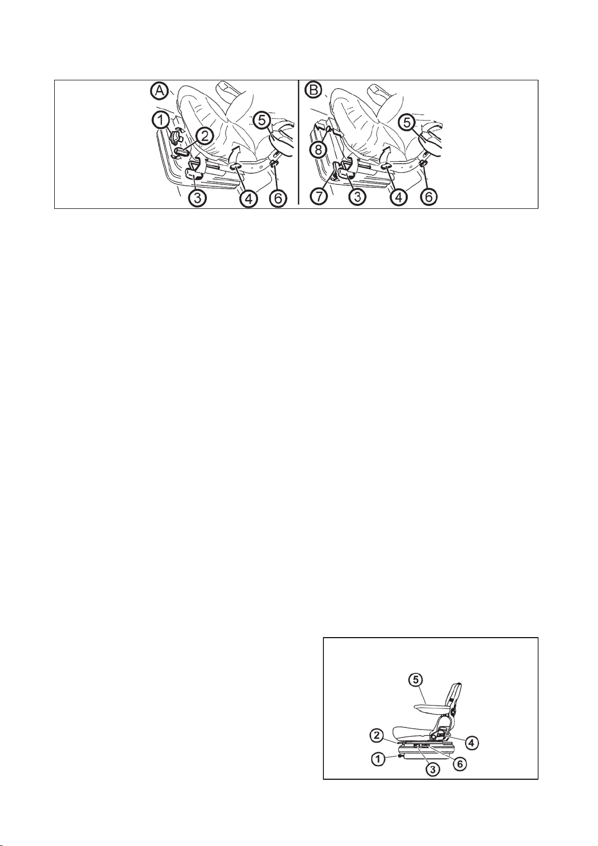
Driver's seat Sears
ACQUAINTANCE WITH THE TRACTOR
3030
P13N003
The driver's seat Sears can be made with a mechanical (A) or pneumatic (B) suspension.
1 - The seat suspension adjustment controller according to the driver's weight (turn it in the direction based
on icons shown on the seat bellows)
2 - The seat height adjustment controller (release the controller to increase the seat height, tighten the
controller to decrease the seat height)
3 - The longitudinal seat adjustment lever (pull the lever to adjust the seat lengthwise, return the lever back
to its original position to lock the longitudinal adjustment)
4 - The seat backrest inclination adjustment controller (pull the lever to adjust the seat backrest inclination,
return the lever back to its original position to lock the backrest position)
5 - Foldable armrest
6 - The armrest height locking adjustment (release the controller to adjust the height of the armrest, tighten
the controller to lock the armrest position)
7 - The seat vibration absorption setting (move the controller up to get the float seat position, move the
controller to the lower position to lock it)
8 - The seat height adjustment and seat suspension adjustment according to the weight of the driver (push
the controller to increase the air pressure in the pneumatic suspension of the seat - when the driver´s weight
is bigger, pull the controller to decrease the air pressure in the pneumatic suspension of the seat - at the
lower weight of the driver
Driver´s seat
1 - The control of setting the seat suspension according to the driver´s weight (setting by rotation, in the
direction according to pictogram on the boot of the seat)
2 - Longitudinal setting of the seat lever
3 - Seat vibrations absorption control (by tilt over of the control forward, floating position of the seat is
engaged)
4 - Setting the angle of rest control
5 - Tilting elbow rest
6 - Pneumatic suspension of seat setting control (by pulling in the direction upward, the rigidity of the
suspension increases, by pulling in downward direction, it decreases)
Driver´s seat with mechanical suspension
Control according to points 1, 2, 3, 4 and 5
Point 2, lever is placed on the right
Driver´s seat with pneumatic suspension
Control according to points 2, 3, 4, 5 and 6
Point 2, lever is placed on the left

Tilting and protrusion of steering wheel
f
(2) by
.
ACQUAINTANCE WITH THE TRACTOR
3131
Tilting column of steering wheel enables variable setting o
position of the steering wheel both in terms of angle and
height.
Height setting of steering wheel
The setting is done by protrusion or retracting the steering
wheel after unlocking arrestment by turning a lever (1) in
the direction of an arrow. After setting the steering wheel,
lock the lever (1) by tightening in the direction of an arrow.
Angle setting of steering wheel
Setting is done by tilting the steering wheel after unlocking
the lock by turning the lever (2) in the direction of the
arrow. After setting the steering wheel, secure the lever
retightening against the direction of the arrow
*Air filter with active carbon
F205
F13BN015
Active carbon filters are installed in the placed of standard dust filter and the replacement is done in the
same way as with standard filters. Filter must be inserted with the white side to the grid. Assembly
instructions are found in the chapter 'Maintenance instructions'.
Filter is used only when spraying pesticides, then it must be replaced back by a paper filter because the
flying dust would clog the carbon filter very fast.
The recirculation control must be in the position 'air is sucked from the outside'.
Ventilator control must be in the position 'maximum ventilator run'.
WARNING: filter does not provide full protection against toxic substances
- Wear protective gloves when manipulating with the filter
- Do not clean the filter and do not blow through with compressed air
DANGER: Replace the active carbon filter every 200 hours or 36 months (date of production is
given on the filter). If you happen to smell pesticides in the cabin, replace the filter immediately and
have the sealing of the cabin checked. Used filters must be damaged in specialized collection
centres .
When spraying pesticides and using heating filters with active carbon, the recirculation
control must be in the position of 'air sucked from the outside' and the ventilator control 'maximum
ventilator run' for creating surplus pressure in the cabin.

Heating control panel, * air-conditio
n
ACQUAINTANCE WITH THE TRACTOR
3232
A - heating valve control
B - ventilator control
C - air-condition switch
D - air circulation in the air of cabin lever
Heating valve control (A)
a - heating valve closed
b - heating valve opened
F13BN009
Ventilator control (B)
0 - ventilator off
1 - slowly run of ventilator
2 - medium run of ventilator
3 - maximum run of ventilator
Switch air-condition (C)
Do engagement and disengagement of air-condition
system function by switching the switch with a symbol of
snow flake (C).
You will set the air-condition system going by pressing the
switch (the symbol of snow flake lights up).
You will disengage the air-condition system by repeated
press of switch (snow flake symbol switches off).
F_02_16_a
F_02_16_b
F_02_17a

Air circulation in cabin control (D)
ACQUAINTANCE WITH THE TRACTOR
3333
a - Surrounding (outside) air is sucked in through filters to
cabin - sucking the air from cabin is closed.
b - Air is sucked in from the space of the cabin and again
blown off to the cabin (inner air recirculation for fast
adjustment of temperature in the cabin).
The intake of air from the outside of the cabin is
completely locked and there is no surplus pressure in
the cabin which would prevent pervasion of unfiltered
air to the cabin! Do not use this position of the control
with work of the tractor!
Proper function of the heating and air-condition system
It is necessary to create surplus pressure in the cabin for
proper function of the heating or air-condition. We
therefore recommend you to close all the windows and
doors and tilting cover of the cabin.
F_02_17b
Fast heating of the cabin area
Proceed accordingly:
1 - Turn the heating valve control (A) to the position on the
right (fully opened heating valve).
2 - Set air circulation in cabin control (D) to the position of
inner circulation.
3 - Select applicable gear of the ventilator run (position 1,
2, 3) by ventilator control (B).
4 - Set the expiration under the requested angle to avoid
direct fanning of the people in the cabin.
5 - After heating the space of the cabin, set the air
circulation in the cabin control (D) to the position of
sucking the outer air - see fig. F_02_17b position (a)
Fast cooling of the space of the cabin
Proceed accordingly:
1 - Switch the heating valve control lever (A) to the
position to the left
2 - Set the air circulation in the cabin lever (D) to the
position of outer air sucking
3 - Select an applicable gear of the ventilator run (position
1, 2, 3) by ventilator control (B)
4 - Switch the air-condition system by a switch (C)
5 - Set expiration under the requested angle so that direct
fanning of people in the cabin does not occur (the
possibility of illness due tointensive cooling of parts of
body).
F11N009
F_02_18a
F_02_18

Operation of heating or air-condition with tractor´s work
p
ACQUAINTANCE WITH THE TRACTOR
3434
With engaged inner recirculation of air is the inflow of
fresh air closed and there is foul air in the space of the
cabin by operator. This state can cause the feeling of
fatigue and there can also be penetration of dust to the
cabin because of the loss of surplus pressure.
Note: Set the control (D) according to individual
requirements on temperature to the position between (a)
and (b) so that the ventilator sucks the air from the outside
of the cabin through filters, when working.
When spraying pesticides and using the
heating filter with active carbon, the recirculation
controller should be in position 'air is drawn into from
the outside' and the fan controller should be in the
osition 'fan maximum work' to create overpressure
in the cabin.
Immediately after cooling the cabin
Immediately after cooling the cabin and lowering the inner
temperature on the required values, we recommend the
following:
- Switch over the control of air circulation (D) from position
(b - air re-circulation) to position (a - outer air suction)
- Do the continuous regulation of the air temperature with
air condition on by opening the heating valve (A). The air
entering the cabin from expiration is not so intensively
dried with this setting.
- Continuous temperature control with air-condition on can
be also done by lowering the output of ventilator by
switching the control (B) to position 1 or 2.
F_02_19
Air-condition and heating registers (A)
F13BN010
Positionable heating and * air-condition registers, front (A), rear (B).
F_02_20

Front windshield (B) defrostin
g
ACQUAINTANCE WITH THE TRACTOR
3535
To ensure quick defrosting of the front windshield direct
the central heating outlets (1) under the angle of approx.
45° towards the windshield. Direct the side outlets (2)
under the angle of approx. 45° to the cab corners.
After defrosting of the front windshield direct the side
outlets to the side glasses of the doors as necessary and
gradually defrost them. After defrosting direct the outlets in
such a way that the air should not be blown directly to the
driver, but down to the driver's legs.
Sun screen
You can draw out the sun shield by pulling the handle in
the direction of the arrow. The shield gets back to initial
position after pressing the button (1) by an applicable
shield.
F13BN011
Internal lighting
To be turned on and off by means of a button marked with
the arrow.
FH13N013
F13BN014

Dashboar
d
ACQUAINTANCE WITH THE TRACTOR
3636
FHD14N036
Description
A - controls
B - coolant thermometer
C - fuel gauge
D - pressure gauge
E - speedometer
F - display
Controls and buttons
When switching the key in switchbox from '0' position to '1' position, all controls light up.
1 - High beam lights (blue). Lights up with high beam lights on.
2 - Tractor turn signal indicator (green).
st
3 - Turn indicator control of 1
4 - Turn indicator control of 2
trailer (green).
nd
trailer (green).
5 - Minimum air pressure in brake system control (red). It is lit up with the pressured drop for air brakes of
trailer under the critical interval i.e. 450 kPa.
6 - Manual brake (red). It is lit with engaged manual brake.
7 - Charging (red). With engine run, lights up with charging disorder. If the engine is at standstill, it must be
lit.
8 - Lubricating (red). With engine running lights up with the oil pressure drop under 120 to 60 kPa. If the
engine is at standstill, it must be lit up.
9 - Air cleaner clogging (yellow). Lights up with air filter clogging.
10 - (not connected)
11 - (not connected)
12 - (not connected)
13 - Indicator (red) of a failure in the hydrostatic control system. It lights with engine operation in hydrostatic
control failure. If the engine is at standstill, it must be lit up.
14 - (not connected)
15 - Diesel particle filter control (red), for more see 'Driving operation'
16 - Diesel particle filter control (green) , for more see chapter 'Driving operation'
17 - Engine ignition (yellow). Signalizes the activity of device for easement of the start of the engine
18 - (not connected)
19 - Fuel (orange). It lights up with the remaining 1/6 - 1/10 of the volume of the tank.
20 - Gearbox disorder control (red), for more see 'Driving operation' chapter
21 - Gear box oil filling overheating control (red), for more see chapter 'Driving operation'
22 - signal lamp of full pushing filter (red); more information in chapter Driving in article Signal lamp of full
pushing filter
23 - Rolling up in the menu button
24 - Rolling down in the menu button
25 - entry to the menu button, confirming items on the menu
26 - LCD backlight inversion button
27 - Reset button hours of operation and km
28 - Change of display button (road, PTO, Moto hours, km).

Display descriptio
n
gag
ACQUAINTANCE WITH THE TRACTOR
3737
The following values are displayed on the display:
1 - shifted gear of multiplier of torque, according to shifted
gear L, M or H is displayed
2 - switching the switch of torque multiplier preselection
3 - switching the function of rear PTO shaft automatic
disengagement
4 - gear shifting lever position, reversing F driving forward,
N neutral, R reversing
5 - road and reduced speeds shifting lever position,
reduced speeds, neutral or road speeds
6 - main depicting field
7 - secondary displaying field
8 - engagement of front axle drive switch
9 - en
ement of rear differential lock
Change of the look of display
The change of look of display from display (1) to display
(2) can be done by pressing a button (A).
FHD14N005
FHD14N027
Display - change of display
FHD14N001
By repeated pressing of button (A), you can click between individual displays of data on display:
1 - Main field travel speed of tractor pole, secondary field of PTO shaft revolution, if it is on
2 - Main field of PTO shaft revolution if it is on, secondary field of travel speed of tractor
3 - Automatic disengagement of rear PTO shaft, more in the chapter 'Drive of agricultural machinery'
4 - Main field of number of hours in operation in total, secondary field of hours in operation from the last
resetting of the data
5 - Main field of the number of kilometres in operation in total, secondary field number of kilometres in
operation from the last resetting of the data
6 - Accumulator battery voltage
7 - The main array machined area in hectares, secondary array in hectares, secondary array hourly
performance, i.e. mean machined area in hectares per hour.
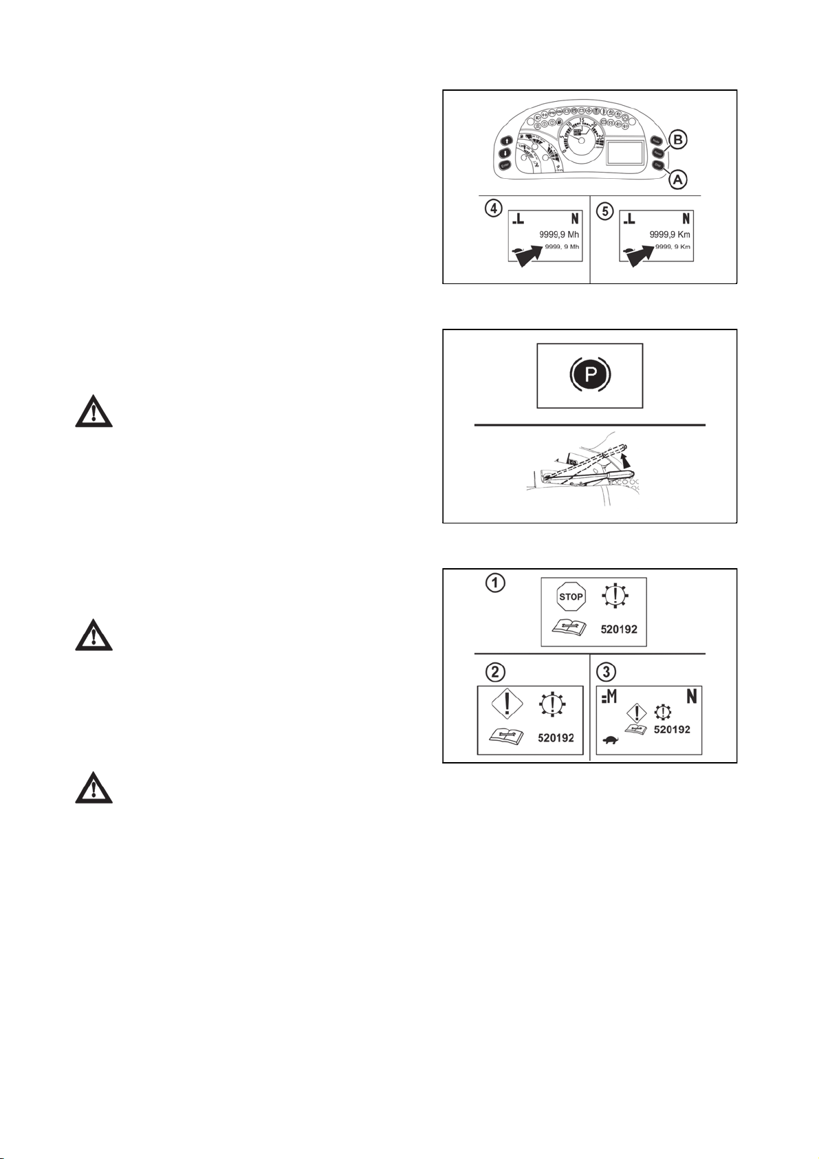
Display - resetting dat
a
ACQUAINTANCE WITH THE TRACTOR
3838
Resetting data marked with an arrow can be done on
a display (4) and (5). Select display (4) or (5) with a button
(A) and by a longer pressing of button (B) reset data
marked with an arrow.
Display - manual brake
If the tractor is not braked by a manual brake, a warning is
displayed on a display (letter P in a circle) and at the same
time a sound signal is heard. See the chapter 'Driving
operation' for more.
Brake the tractor by a manual brake.
FHD14N059
Display - error messages
Serious faults in the system (1)
STOP sign, number of fault (1) is displayed on a display
with serious faults.
If this situation occurs, set the tractor aside and
contact service.
Less serious faults in the system (2) a (3)
With less serious faults in the system, the number of faults
(2) are displayed on the display for a time period of
approximately 5 seconds.
Then the display of fault is minimized to the main field. (3)
If this situation occurs, complete the work and
contact service.
See more in the chapter of 'Driving operation'.
FH12N039
FHD14N002

Display - service men
u
ACQUAINTANCE WITH THE TRACTOR
3939
Entry to service menu:
You will enter the service menu by a longer pressing of (A)
button.
The selection of items to be done by (B) and (C) buttons.
The selected item is marked by an arrow (1).
Exit from service menu:
By buttons (B) and (C), select an item EXIT and press (A)
button.
Service menu
1 - Failures history, for servicing purposes
2 - Machined area
3 - Calibration
4 - Language selection
5 - Exit service menu
FHD14N003
Display - setting language mutation
Enter the service menu:
Select the item LANGUAGE by (B) and (C) buttons and
press button (A).
Select language mutation by buttons (B) an (C) and by
one by one presses of button (A) available language
mutations will be one by one displayed. When achieving
the desired language mutation, leave the service menu.
Select EXIT item by using (B) and (C) buttons and press
(A) button.
Dashboard is switched to a selected language mutation.
If you want to change metric units to Anglo-
Saxon, select language mutation ENG. IMP.
Display - machined area
Machined area displays machined area in hectares in the
main displaying array, in the secondary displaying array
mean in hectares per hour.
It is necessary to set the width of the machined
area (i.e. working width of the tools) for the correct
calculation of machined area.
FHD14N028
FHD14N004
FHD14N030
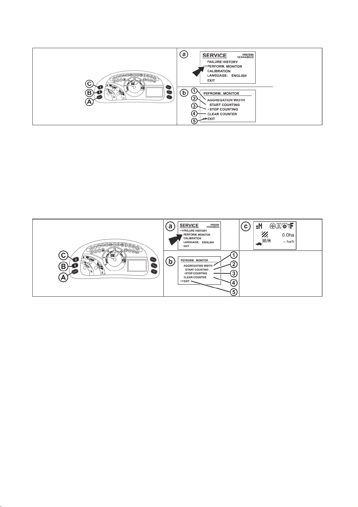
Machined area men
u
ACQUAINTANCE WITH THE TRACTOR
4040
FHD14N037
Enter service menu by pressing (A) for a longer period of time. Select an item machined area marked with an
arrow (a) by (B) and (C) buttons. By pressing (A) button, you will enter the machined area (b) menu.
Machined area (b) menu:
(1) - setting the width of machined area (i.e. working width of tools)
(2) - start of machined area record
(3) - end of machined area record
(4) - erase recorded area from ECU
(5) - return to service menu
Machined area width
FHD14N066
Enter machined area menu. Select the item aggregation width marked with an arrow (a) by (B) and (C)
buttons and by pressing the button (A) shift to the menu aggregation width. There are three preset values of
aggregation width in aggregation width menu. Select the required aggregation width by (B) and (C) buttons
and confirm by pressing (A) button. Select an item (1) by (B) and (C) buttons and press (A) button for return
to machined area (a) menu.
Setting aggregation width
In aggregation width menu, each of the three preset values of aggregation width can be changed.
Enter aggregation width menu, select the value (c) you want to change by (B) and (C) buttons.
After pressing the (D) button, the value (2) starts blinking, it can be changed by (B) and (C) buttons.
After you press the (D) button again, a value starts to blink (3), you can change the value by (B) and (C)
buttons.
After you press the (D) button again, a value starts to blink (4), you can change this value by (B) and (C)
buttons.
The newly set values will be saved by pressing the (A) button.
Then continue by changing each preset value or select return to the machined area (a).
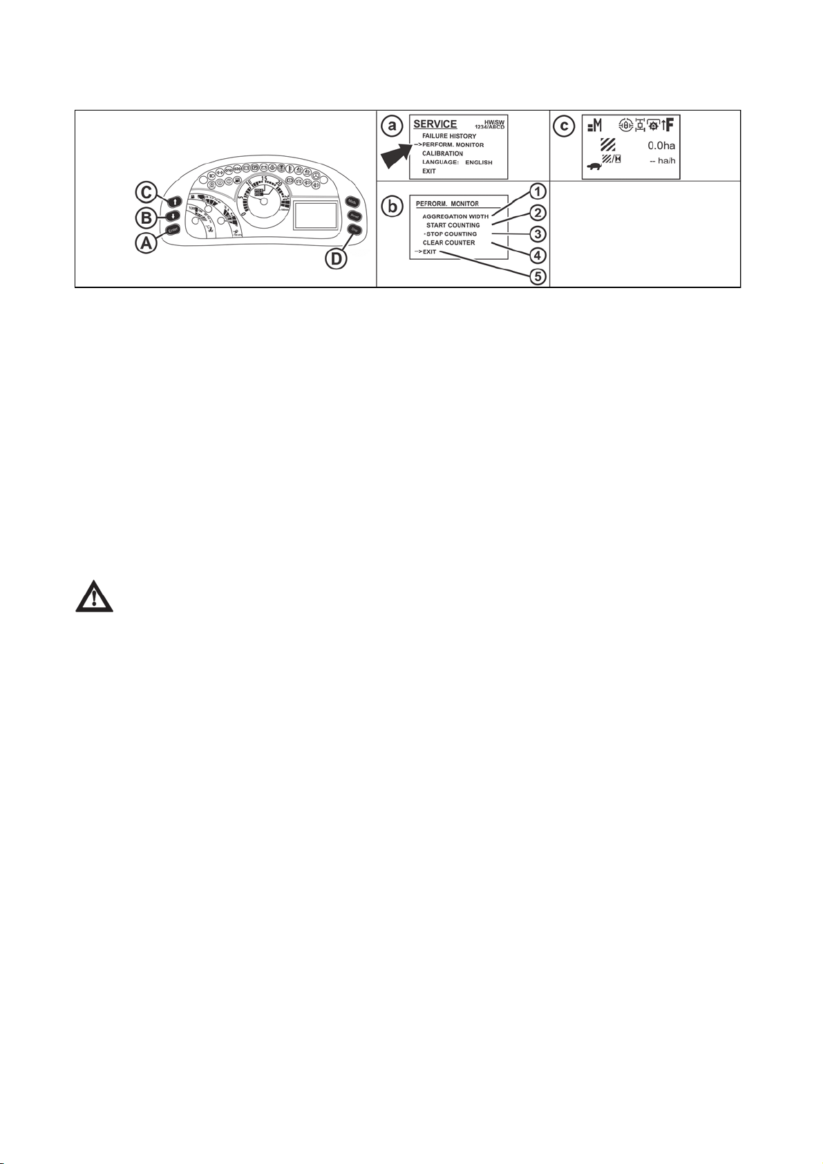
Machined area recor
d
ACQUAINTANCE WITH THE TRACTOR
4141
FHD14N070
Enter service menu (a) by longer pressing the (A) button. Select the item machined area marked with an
arrow by (B) and (C) buttons. By pressing the(A) button, you will enter the machined area menu (b).
Select an item (1) by (B) and (C) buttons and in the aggregation width menu select a requested value and
return to the machined area(b) menu.
Select an item (2) by (B) and (C) button and by pressing the button (A) start recording of machined area and
exit service menu. From this time on, if the tractor is moving, machined area will be recorded depending on
the aggregation width and the travelled distance.
The record of the machined area will end if you select item (3) in the machined area menu(b) and press (A)
button.
If you start the record of machined area again, the newly read values will be added to the already saved
values.
After annulling the values in the main and secondary array, select an item (4) in the menu by (B) and (C)
buttons in the machined area menu(b) and by pressing the (A) button, confirm the selection. After returning
to the main screen Machined area, there will not be any data in the main and secondary array of the display
(c).
Overridden values cannot be renewed in any way.
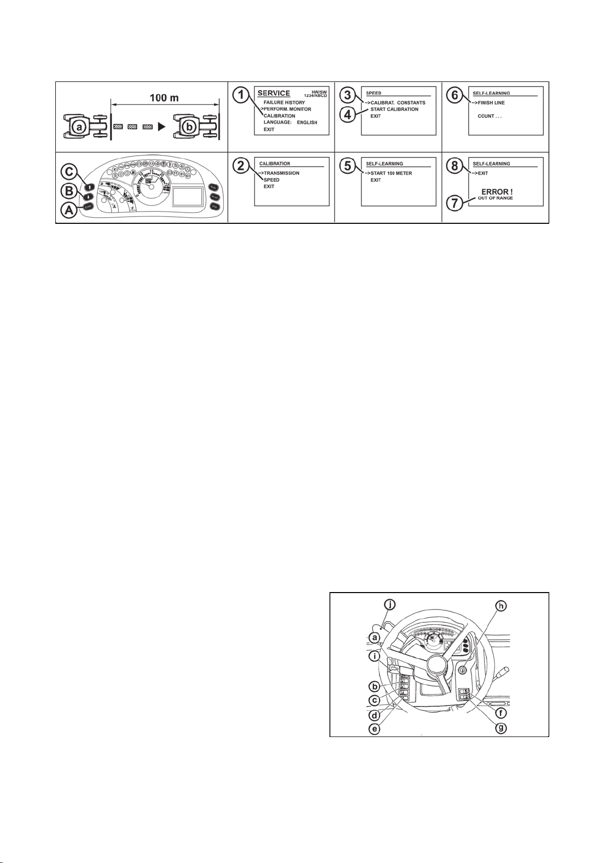
Travel speed calibration digital dashboards
j
ACQUAINTANCE WITH THE TRACTOR
4242
FHD14N072
Dashboard is calibrated after assembly at a production plant.
Do repeated calibration in the following cases:
- after a significant wear of tyres
- when mounting new tyres
- when replacing dashboard
Calibration procedure
- at a suitable place, mark a track of 100 m at length
- inflate tyres of tractor on the prescribed pressure, see tables of this Instructions manual
- start the engine
- move the tractor to the beginning of the 100-metre track (a)
- enter the service menu by pressing (A) button
- select the item (1) by (B) and (C) buttons and by pressing (A) button go to calibration menu
- select the item (2) by (B) and (C) buttons and move to the speed menu by pressing (A) button
- select an item (4) by (B) and (C) buttons and by pressing the (A) button, move to the following menu. The
item (3) serves only for setting the travelling speed in the production plant
- select an item (5) by (B) and (C) buttons and confirm with the (A) button
- start the tractor with a stable speed of approximately 10 km/h
- after travelling the whole distance of 100 m stop the tractor at the marked end of the track (b)
- select the item (6) by pressing the buttons (B) and (C) and by pressing (A) button, save the newly read
values and you will return to initial screen
- if calibration of travelling speed did not run properly, error report will appear on the display (7), after
confirming the item (8) you will return to initial screen by pressing the (A) button without saving the new
values
Switches and levers
a - lights switch (off, parking, head)
b - lower beam lights in the grill of the tractor and working
lights in the cabin of the tractor switch
c - Fog light switch (off - on). Fog light function is
signalized by a lit symbol on the switch.
d - Working lamp switch (off - on). Working lamp function
is signalized by a lit symbol on a switch.
e - warning lights switch
f - beacon switch (off - on)
g - working lights in the grill of the bonnet switch (off - on)
h - switch box
i - direction lights, lower beam head lights, head lights and
horn switches acoustic and light
- reversing lever (forward, neutral, backward)
FHD14N073

Lights switc
h
ACQUAINTANCE WITH THE TRACTOR
4343
a - illumination off
b - side and end point lights on, illumination of licence
label, illuminated
c - all devices on in 'b' position. Lower beam head lights or
head beam lights are engaged (according to the position
of direction lights, lights and horn switches).
Switch of warning lights
a - warning lights on
b - warning lights off
Function of warning lights is signalized by interrupted
blinking control on the dashboard.
F56
Lights switch between the grill and the cabin
a - roof lights on
b - roof lights off
The switch controls the illumination in the grill or in the
roof of the cabin of the tractor. Use the lights in the roof of
the cabin only when tools covering headlights in the grill is
attached in front three-point hitch. A lit symbol on the
switch signalizes light on in the roof.
Headlights can be lit only in the grill of the bonnet.
Direction lights, lower beam head lights, head lights and horn switches
a - Acoustic horn - press the switch in the direction of an
axis
b - Lower beam head lights
c - Direction lights to the right
d - Direction lights to the left
e - Acoustic horn
f - Lower beam headlights
F58
F59
X139

Switch box
k
ACQUAINTANCE WITH THE TRACTOR
4444
Switchbox is placed on the dashboard, see arrow.
Switch box key in the position (0)
The voltage of all the equipment controlled via the key is
disconnected. The key can be removed.
F13BN004
Switch box key in the position (I)
The voltage is connected to all the equipment excluding
starter. The key is in this position with the engine running.
Switch box key in the position (II)
Starter and supply of all equipment is connected in this
position apart from wipers, washer, cab ventilator and air
condition. After starting, the key automatically returns bac
to 'I' position.
S43
S44
S45
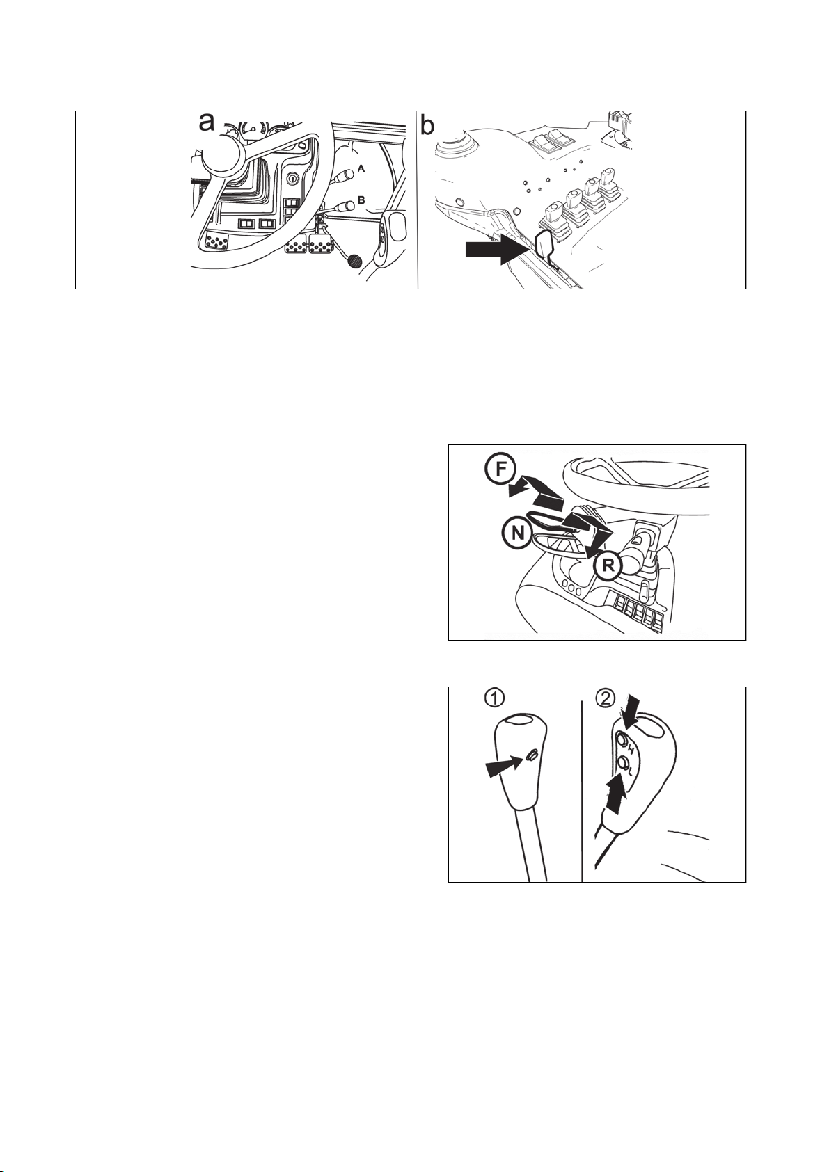
Manual throttle
ACQUAINTANCE WITH THE TRACTOR
4545
FHD14N078
A - maximum supply
B - idle run
(a) for tractors with engine with mechanical control of revolutions
(b) for tractors with engines with electronical control of revolutions
Reversing lever
F - front driving; lever in the front
N - neutral
R - back driving; lever at the back
Gear shifting lever
- main gear shifting lever
1. button for disengaging clutch on the head of gear
shifting
2. buttons of shifting individual gears of multiplier
X212a
FH12N037
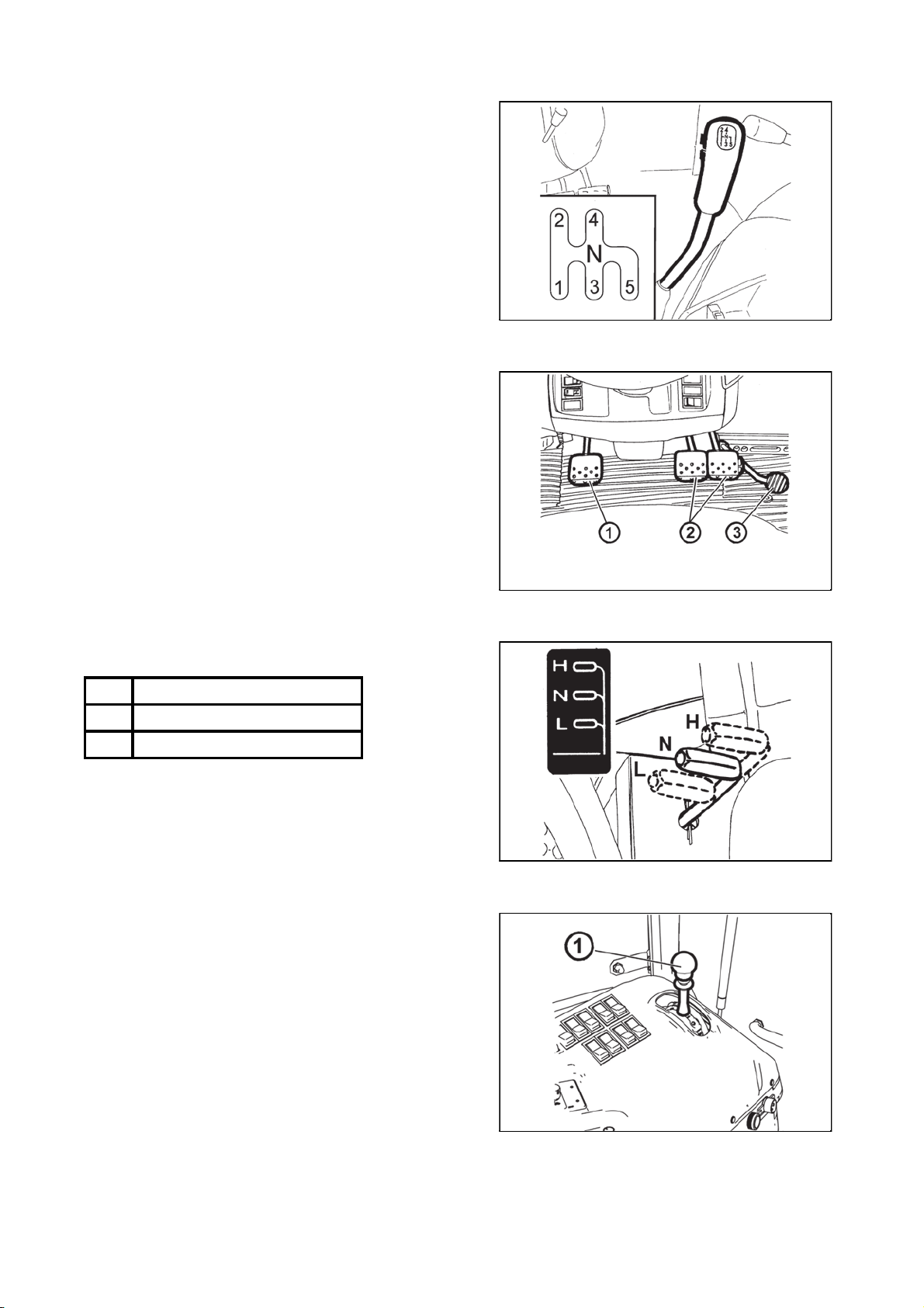
Gear shifting scheme
ACQUAINTANCE WITH THE TRACTOR
4646
Reversing speeds can be shifted only by means of
reversing lever. The scheme is placed on the head of gear
shifting lever.
Pedals and levers
1 - travel clutch pedal
2 - foot brake pedals joint by a catch
3 - throttle pedal
FH12N038
Road and reduced speeds shifting lever
The lever is placed on the right side of driver´s seat.
H - Road speeds
N - Neutral
L - Reduced speeds
PTO revolutions preselection lever
The lever (1) is placed on the right side of driver's seat.
For more information see the chapter on Drive of
agricultural machines.
FHD14N083
F72
FHD14N026

Manual brake lever and coupling for semi-trailer control leve
r
ACQUAINTANCE WITH THE TRACTOR
4747
1 - manual brake lever
a - unbraked
b - braked
2 - coupling for semi-trailer lever
a - transporting position
b - bearing hooks folded up; tow hook with carrier can be
started
Battery disconnector
Disconnect the battery immediately by battery
disconnector which is placed on the right side of the
tractor with long-term standstill, repairs or accident.
a - battery connected
b - battery disconnected
F74
Fuel tank
A plastic tank of 240 litres volume is mounted as
a standard for all types of tractors.
Do not step on the fuel tank!
Fuel tank drain plug
Plug for draining dirt and fuel off the fuel tank is in its
bottom.
FH12N022
F_02_22
H800

Aggregation openin
g
ACQUAINTANCE WITH THE TRACTOR
4848
Aggregation opening serves for cabelling or Bowden
control of aggregated tools placement.
Pull to protrude the part of sealing of rear window in
upward direction. Put the aggregated tool control through
the originated hole.
Insert cabelling or Bowden controls to the holes of
passage of aggregation opening. Return the sealing of the
rear window to its original position by exercising pressure.
F11N091

Before a drive with the new tractor get to know how to shift gears and try individual positions
p
.
p
DRIVING OPERATION
49
49
of the shifting lever when the engine is stopped.
During normal operation and before you set up, make sure that the technical condition ensures safe
operation of the tractor.
Before you start
Before you start the engine, make sure that:
1. the tractor is properly braked.
2. the main gear shifting lever of gears in neutral
osition
3. Reversing lever is in neutral position
4. PTO switches are off
If clutch pedal is not depressed the tractor cannot be
started - start protection switch is not switched
FHD14N038
If you do not succeed in starting the engine
Return the key to '0' position. Wait 30 second and repeat
the start.
Never help the stopping engine by a starter.
You are being exposed to the danger of starter
damage.
Non-permitted starting
It is forbidden to start the tractor by shortcircuiting the starter clamps. Start only from the
driver´s seat. It is necessary to disconnect minus pole
of accumulator and all the shifting levers including
PTO shaft shifting lever to be shifted in neutral
osition with any manipulation or repair of the starter.
The starter´s clams are covered with a cap.
F11N012
F11N013

Starting the engine of the tracto
r
DRIVING OPERATION
50
50
As a standard, the tractors are equipped by glow plugs in
the heads of rollers.
When starting the engine, it is necessary to sit
on the driver's seat.
1. Insert the key to the switchbox ('0' position).
2. Depress the clutch pedal.
3. Shift the main gear shifting lever to neutral position.
4. Shift the reversing lever to neutral position.
5. Make sure that all PTO switches on the right column of
the cabin are switched off.
6. Turn the key to 'I' position. A yellow control will light up
on the dashboard signalising the proper igniting function.
7. Wait for the ignition control to turn off (the time is
dependent on the temperature of the coolant).
If the ignition control merely blinks instead of
lighting up, there is a disorder in the ignition system
(see ch.: Ignition system disorder signalization). The
signalised fault must be resolved in an expert service
garage.
8. Turn the key to the 'II' position (start).
9. After starting the engine, release the key immediately.
Do not start for more than 15 sec.
FHD14N039
FH12N052
Ignition system disorders signalization
Ignition system disorders are signalized by blinking of ignition control.
- If ignition control blinks at standstill once per second, ignition in emergency system occurs just like at low
temperatures regardless of the temperature of coolant.
- If the ignition control blinks at standstill twice per second, the ignition is put off operation (does not work).
- If the ignition control blinks permanently during the run of engine, there is a disorder of ignition control and
ignition has not been completed. The disorder must be forthwith removed, because there is the danger of
battery depletion.
*Coolant heater
Coolant heater is mounted on the engine block.
The heater has the output of 1000 W with voltage of 220
V of electric alternate current.
F11N016

Starting the engine with the use of coolant heate
r
.
DRIVING OPERATION
51
51
F91
Heating the coolant makes starting the engine easier with low temperatures. Inlet electric installation and its
protection against dangerous touch must be done in accordance with valid regulations.
1. Insert the plug to the heater first.
2. Then connect the heater to the electric network of the voltage of 220 V.
With regard for the lower engine wear when starting at low temperatures, the use of heater is recommended
by the manufacturer. The duration of heating is dependent on the surrounding temperature (1 - 2 hours
before scheduled start should suffice).
After completing the heating, first disconnect the device from the electric network and only
then pull the plug out of the heater!
The danger of injury by electric current! It is necessary to ensure instruction of the tractor´s operator
and regular revision of the heater of coolant including inlet cable in the sense of valid standards of
the state in which the tractor is operated at least before every winter season.
Immediately after start
After start, set the revolutions for 800 - 1000
revolutions per minute, allow the engine to run for
a time period of approximately 2 minutes.
In this time, do the control of greasing, recharging,
hydrostatic steering (the controls must turn off) and other
functions ensuring proper run of engine. The time of
engine operation without load must be kept, in particular in
winter season
FH11N092

Engine heatin
g
DRIVING OPERATION
52
52
FH11N091
Do further heating of the engine during the drive. The heating of the engine by lengthy idle run
or sharp increase in revolutions is harmful to the engine. If the temperature of coolant has not
reached 45°C, do not exceed the engine revolutions over 2000 rpm.
Gear shifting
The tractors are equipped with a five-gear synchronized
gearbox, three-gear torque multiplier, reversing and twogear reduction.
Five-gear gearbox is shifted by main shifting lever with
buttons for disengaging the travel clutch (1) and for
shifting the individual gears of multiplier (2).
Reversing lever
The selection of the direction of travel drive is done by
reversing lever (forward, backward).
F - driving forward
N - neutral
R - driving backward
The lever also serves for starting the tractor without the
depressed clutch pedal.
FH12N037
X212a

Reversing lever position signalizatio
n
t
DRIVING OPERATION
53
53
The individual positions of reversing lever are signalized
by a sign (1) in the top right corner of the display.
driving forward
Neutral
driving backward
Shifting road and reduced speeds
H - Road speeds
N - Neutral
L - Reduced speeds
Shifting the gears of the main gearbox with reduced
speeds is the same as with road speeds.
FHD14N040
Road and reduced speeds shifting lever can be
shifted only with a tractor at standstill.
Road and reducing speeds lever position signalization
The individual positions of road and reduced speeds lever
are signalized by a sign (1) in the left bottom corner of the
display.
road speeds
neutral position
reduced speeds
Driver´s seat - safety switch
The driver´s seat is equipped with a safety switch which
signalizes the system of driver abandoning the driver´s
seat.
If the tractor is started, there is nobody on the driver´s sea
and reversing lever under the steering wheel is shifted to
F or R position, N position is shifted automatically and
tractor does not start.
If this situation occurs, it is necessary to sit on the driver´s
seat, to return the reversing lever under the steering wheel
to N position and then to select the direction of drive again
(F or R).
F72
FHD14N041
FH12N069

The principles of appropriate use of tractors
DRIVING OPERATION
54
54
The listed principles for tractor´s operation serve for facilitating the operation and guarantee
corresponding service life of travel clutch!
The description of the system of travel clutches
The tractor is equipped with two individual travel clutches, one for travelling forward and one for travelling
backward.
The selection of the driving direction and also the choice of a specific travel clutch is done by shifting the
reversing lever under the steering wheel from neutral position to the position forward or backward.
The way of controlling the travel clutch by
1 - Reversing lever
2 - Clutch control button on the head of reversing lever
3 - Clutch pedal
The differences in ways of controlling the travel clutch by
1 - Reversing lever
This way of control has automatic start function.
When shifting the reversing lever to neutral position, there is release of travel clutch.
When shifting the reversing lever to the forward or backward position, there is a switch of travel clutch and
subsequent smooth dead start of the tractor in the direction defined by reversing lever.
The speed of switch of travel clutch and the smoothness of dead start is controlled by a controlling
unit on the basis of information saved in calibration and the operators cannot influence it.
Automatic dead start function is sparing to travel clutches than the control of travel clutches
by clutch pedal, therefore use the ways of controlling travel clutch with the function of automatic
dead start for the regular operation of tractor with dead start, gear shifting or the change of the
driving direction.
2 - Clutch control button on the head of gear shifting lever
This way of control has the function of automatic switch of travel clutch.
When pressing the button of clutch control on the head of gear shifting lever there is release of travel clutch.
When releasing the red button of control clutch on the head of gear shifting lever, there is a switch of travel
clutch.
The rate of travel clutch switch is controlled by electronic control unit on the basis of information saved with
calibration and the operator cannot influence it.
3 - Clutch pedal
When depressing the clutch pedal, there is release of travel clutch.
When releasing the clutch pedal, there is a switch of travel clutch.
The speed of travel clutch switch is dependent on the speed of releasing the clutch pedal.
The clutch pedal does not enable the function of automatic dead start and operators influence the speed and
smoothness of dead start.
Use the clutch pedal only for stopping the tractor in regular operation.
For the need of delicate inching, for example when connecting tools or when manipulating
with the tractor in crammed spaces, when even the reduced gear speeds are not slow enough, use
the clutch pedal for short time.
It is forbidden to control the speed of tractor by partial depression of the clutch pedal with
engine revolutions higher than 1200 revolutions per minute. Do not use the clutch pedal as a foot
rest. There is a danger of limiting service life or failure of travel clutches.

Interrupted sound signal
.
DRIVING OPERATION
55
55
If the speed of tractor is control by partial depression
of the clutch pedal with engine revolutions higher
than 1 200 rpm, there is an interrupted sound signal
and gearbox failure control is still lit. If this situation
occurs, fully depress the clutch pedal immediately to
stop or release the clutch pedal to the upper position
and wait until the sound signal goes silent and the
control of gearbox failure. Lower the engine
revolutions under 1 200 revolutions per minute and
then continue working with the tractor. If you do not
do it, 8 seconds later the interrupted acoustic signal
changes to uninterrupted signal.
FH12N047
Dead start of the tractor
If at dead start, engine revolutions are higher than 1400 rpm L gear of multiplier is automatically shifted, not
depending on the switch of multiplier pre-selection on dashboard being on or off.
If the multiplier pre-selection switch on the dashboard is on at dead start, L gear of multiplier is shifted
automatically independent on the number of engine revolutions at dead start (i.e. when the engine
revolutions are lower than 1400 rpm).
A very fast dead start can cause overloading of driving gear, increased fuel consumption,
st
excessive wear of tyres and damage to load. Use dead start on the 1
gear only when driving with
heavy trailer to the slope and in difficult terrain.
Dead start of tractor in regular operation - automatic dead start function
- Use the control of travel clutch by reversing lever under the steering wheel for dead start of the tractor.
- Select the slowliest L gear of torque multiplier for dead start of the tractor.
Note: When starting or stopping the engine of the tractor, the fastest gear H is always automatically shifted.
- If the road and reducing speeds shifting lever is shifted in the group of road speeds, shift the lowest gear
speed for tractor dead start with respect for operational conditions.
- Use the lowest possible engine revolutions for tractor´s dead start, such that there is no turn off. After the
switch of travel clutch, increase the engine revolutions according to your needs.
Dead start by means of automatic dead start function
Automatic dead start function is in the shift of reversing lever with engaged applicable gear followed by dead
start without using the clutch pedal or clutch control buttons.
1. Start the engine.
2. Shift appropriate gear for starting the engine.
3. Release the manual brake, if you are standing on a slope, brake the tractor by foot brake.
4. When shifting the reversing lever form neutral to the requested direction of tractor drive (forward or
backward), the tractor starts.
5. When you increase the engine revolutions simultaneously, release the foot brake.
When depressing the clutch pedal, the automatic dead start function is put off from operation.
Dead start of tractor in regular operation - clutch pedal
In regular operation use the clutch pedal only for stopping the tractor. For the need of delicate
inching, e.g. when connecting the tools or when manipulating with tractor in crammed spaces, if
even the reduced gears are not slow enough, use the clutch pedal only for short time.
It is forbidden to control the speed of tractor by partial depression of clutch pedal with engine
revolutions higher than 1200 rpm. Do not use the clutch pedal as a foot rest.
There is a risk of limited service life or failures of travel clutches

Dead start - using the clutch pedal
DRIVING OPERATION
56
56
1. Start the engine.
2. Depress the clutch pedal.
3. Select road and reduced speeds.
4. Shift an applicable gear for starting the tractor.
5. Shift the reversing lever to the direction requested (forward or backward).
6. Slightly increase the engine revolutions.
7. Prepare the manual brake for unbraking.
8. Release the clutch pedal only to the point of travel engagement and with simultaneous increase of
revolutions continue in a continuous release of the clutch pedal.
9. Fully unbrake the manual brake.
10. Start smoothly and slowly.
Use this way of dead start when you need to inch carefully, for example when connecting tools
etc.
Change the direction of drive
Change the direction of drive by means of reversing lever
Change the direction of drive by means of reversing lever is done with travel speed lower than
10km/h. When you attempt to change the direction of drive in speed higher than 10 km/h, acoustic
signal starts (uninterrupted tone) and the tractor engages neutral. The signal switches off after the
shift of reversing lever back to N position, when depressing the clutch pedal or pressing the button
of switching clutch on the head of gear shifting lever. It is also necessary to lower the travel speed of
tractor under 10km/h, shift the reversing lever to neutral position and to repeat the shifting of
requested direction.
Keeping the following instructions when changing the direction of the drive, contributes to
prolonging service life of travel clutches.
· For changing the direction of the drive of tractor use reversing lever under the steering wheel without using
the clutch pedal.
· For changing the direction of the drive of tractor, select the slowliest gear L with torque multiplier.
· For changing the direction of the drive of tractor, select lower gear with regard for the subsequent dead
start and tractor load.
Changing the direction of drive by means of reversing lever is done at tractor travel speed
lower than 10km/h. When you try to change the direction of drive at the speed of more than 10 km/h,
an acoustic signal starts (uninterrupted tone), the signal switches off after the shift of the lever back
to N position, when depressing the clutch pedal or pressing the button for switching off the clutch on
the head of the gear shifting lever.
1. Lower the travel speed of tractor under 10km/h by means of brake pedal.
2. Shift the reversing lever to the requested direction of tractor drive.
3. The tractor stops automatically and travels in the requested direction.
4. Continue in smooth dead start of the tractor with simultaneous incresae of engine revolutions.
Should the tractor speed drop below 10km/h, tractor shift neutral and it is necessary to lower
the travel speed of tractor under 10km/h, shift the reversing lever to neutral position and to repeat
the shifting to the required direction.
When depressing the clutch pedal, the automatic function is put off operation. If the above
mentioned is done subsequently after the attempt to change the direction of drive above 10 km/h, it
is necessary to lower the travelling speed of tractor below this speed. In opposite case, after the
release of clutch pedal the neutral remains shifted.
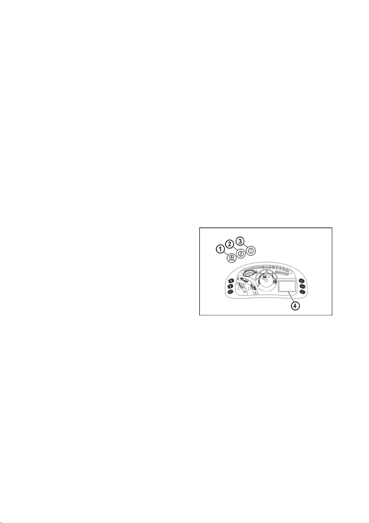
Change the direction of drive - using the clutch pedal
DRIVING OPERATION
57
57
1. Depress the clutch pedal and stop the tractor by foot brake.
2. Shift the reversing lever to the requested direction of tractor drive.
3. Release the clutch pedal only to the point of travel engagement and with simultaneous increase of engine
revolutions continue in smooth release of the clutch pedal.
4. Start smoothly and slowly.
Gear shifting
- For shifting the gear speeds while travelling use the travel clutch control by a red button of clutch control on
the head of gear shifting lever.
- When shifting gears, press and hold the red button of clutch control on the head of gear shifting lever,
release the gas pedal, throw out the gear, shift an applicable gear speed, release the red button and then
increase the engine revolutions.
- If operation conditions permit, use the function of multiplier preselection.
Gear shifting - Using the clutch pedal
Depress the clutch pedal (clutch disengaged). At the same time release the pedal of foot throttle and shift the
applicable gear speed. Release the clutch pedal smoothly (clutch is being engaged) and at the same time
increase the engine revolutions.
Gear shifting - using the clutch control button on the head of gear shifting lever
Press the clutch control button on the head of gear shifting lever. At the same time release foot throttle pedal
and shift the applicable gear speed. Release the button of clutch control (clutch is being engaged) and at the
same time increase the engine revolutions.
Note: Clutch pedal is always preselected to the use of button of clutch control on the head of gear shifting
lever.
Signalization of travel clutches and gear box system failures
The failures in systems of travel clutches and gear box are
signalized by red controls on the dashboard and a failure
code on the display.
1 - Signal lamp of full pushing filter - more information in
article Signal lamp of full pushing filter.
2 - Gear box oil overheating control. If it lights up, interrupt
your work and allow the tractor to run on idle run, until the
oil filling of gearbox cools off and the control switches off.
After the control switches off, you can continue working
with the tractor without restrictions.
3 - Gearbox failure control. It lights up with serious failure
of the system.
4 - Failure code and its description is displayed on the
display.
FH12N059
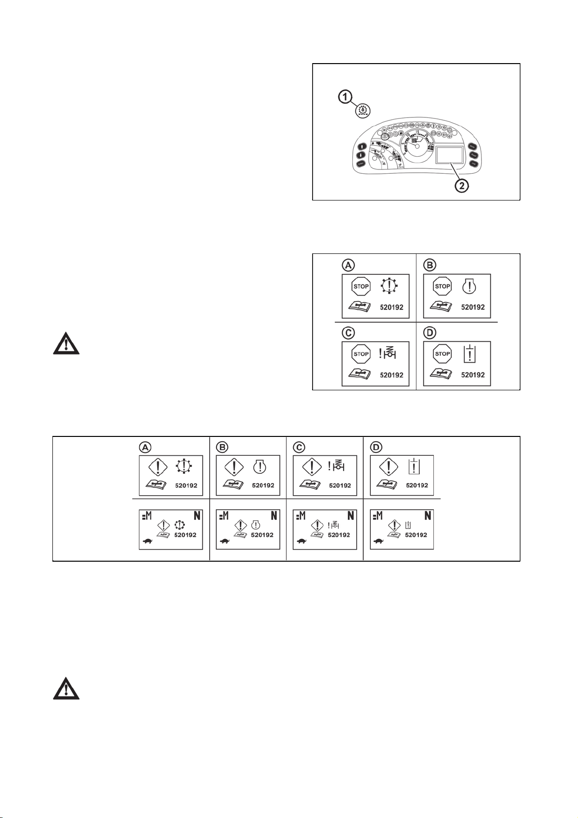
Signal lamp of full pushing filte
r
DRIVING OPERATION
58
58
Signal lamp of full pushing filter (1)
z flashing when engine is running indicates oil
temperature lower than 20°C.More information in
chapter HYDRAULIC DEVICE.
z glow when engine is running indicates full pushing
filter of gearbox distributor or full pushing filter of
hydraulics pump; the following defect code is
shown on the display:
520257 when the pushing filter of gearbox
distributor is full
520266 when the pushing filter of hydraulics pump
is full
Should this be the case, replace the pushing fiter
element according to the defect code.
Major failures signalization
A failure in the category of major failure is signalized by
a non-stop acoustic signal and the display of a number of
failure on the display.
(A) major system failure of travel clutches and reversing
(B) major engine failure
(C) major failure in front drive axle suspension
(D) major failure in hydraulic system
If this situation occurs, put the tractor at standoff and contact a garage forthwith
FHD14N043
Signalization of less major failure
FHD14N044
A failure in the category less major failure is signalized on the display by displaying the number of the failure
for a time period of approximately 5 seconds (1).
Then the display of failure is minimized to the main array (2).
All the functions of the tractor remain active; it can happen that some of the functions will not be full-fledged.
(A) less major failure of the system of travel clutches and reversing
(B) less major engine failure
(C) less major failure of front drive axle suspension
(D) less major failure in hydraulic system
If this situation occurs, finish work and contact a garage.
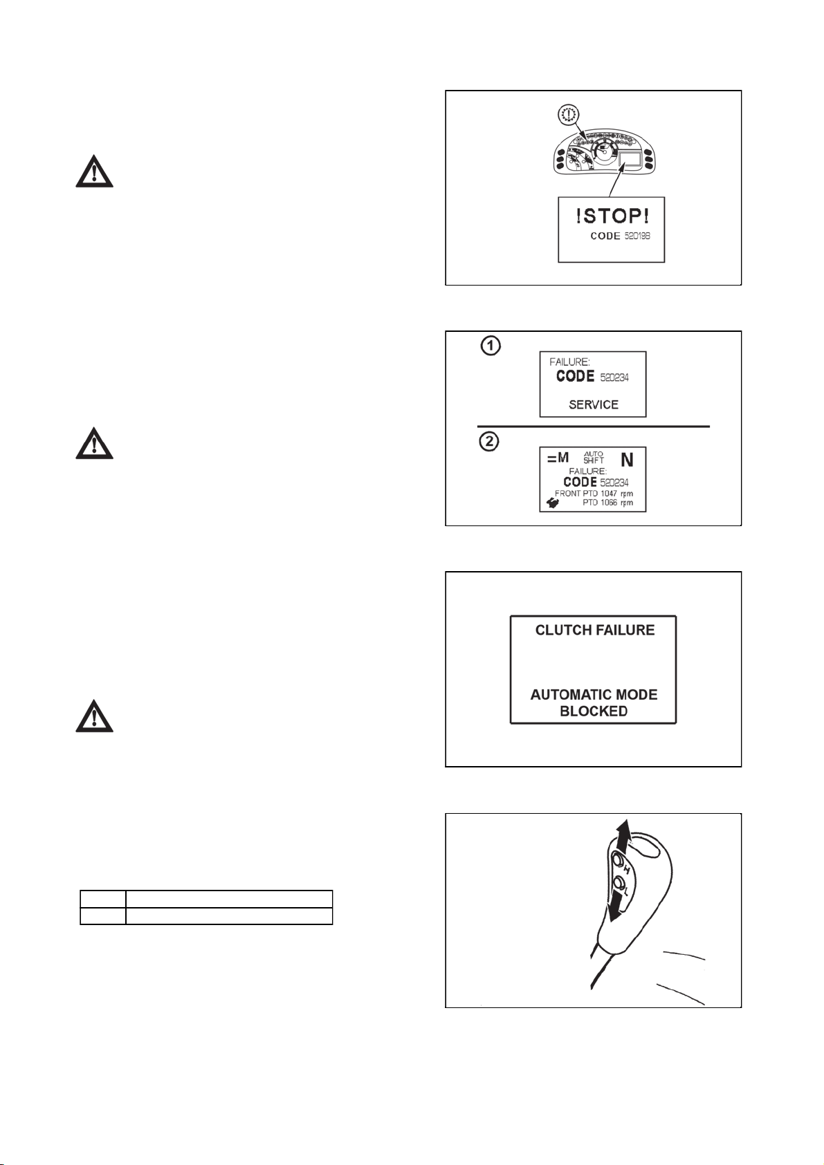
Serious failures of travel clutches and reversing levers syste
m
DRIVING OPERATION
59
59
A failure of serious failure category is signalized by a red
control gearbox failure, there is an uninterrupted acoustic
signal and there is a sign STOP displayed on a display
together with a number of failure.
If this situation occurs, put the tractor aside
and contact the service forthwith.
Less serious failures of travel clutches and reversing system
A failure of a category less serious is signalized on
a display by displaying a number of failure for a time
period of approximately 5 seconds (1). Then the display of
failure minimizes to the main field (2). All the function of
the tractor remain active, it can happen, that some of the
functions will not be complete.
If this situation occurs, finish your work and
contact service.
FH12N060
Blocking the automatic dead start function
With some failures of travel clutches system, the function
of automatic dead start is blocked. This situation is
signalized by an inscription displayed on a display. In this
case reversing lever under the steering wheel serves only
for the selection of direction of drive, the button for clutch
control on gear shifting lever does not work. For dead start
of tractor and gear shifting, it is possible to use only clutch
pedal.
If this situation occurs, finish your work and
contact service.
Three-gear torque multiplier
Three-gear multiplier is a standard equipment of all types
of tractors. Shifting individual gears of three-gear multiplier
is controlled by two buttons on the head of main gear
shifting lever.
H - Increasing travel speed
L - Decreasing travel speed
FHD14N045
FH12N073
It is done without travel clutch pedal depressed (under
load).
FH12N058
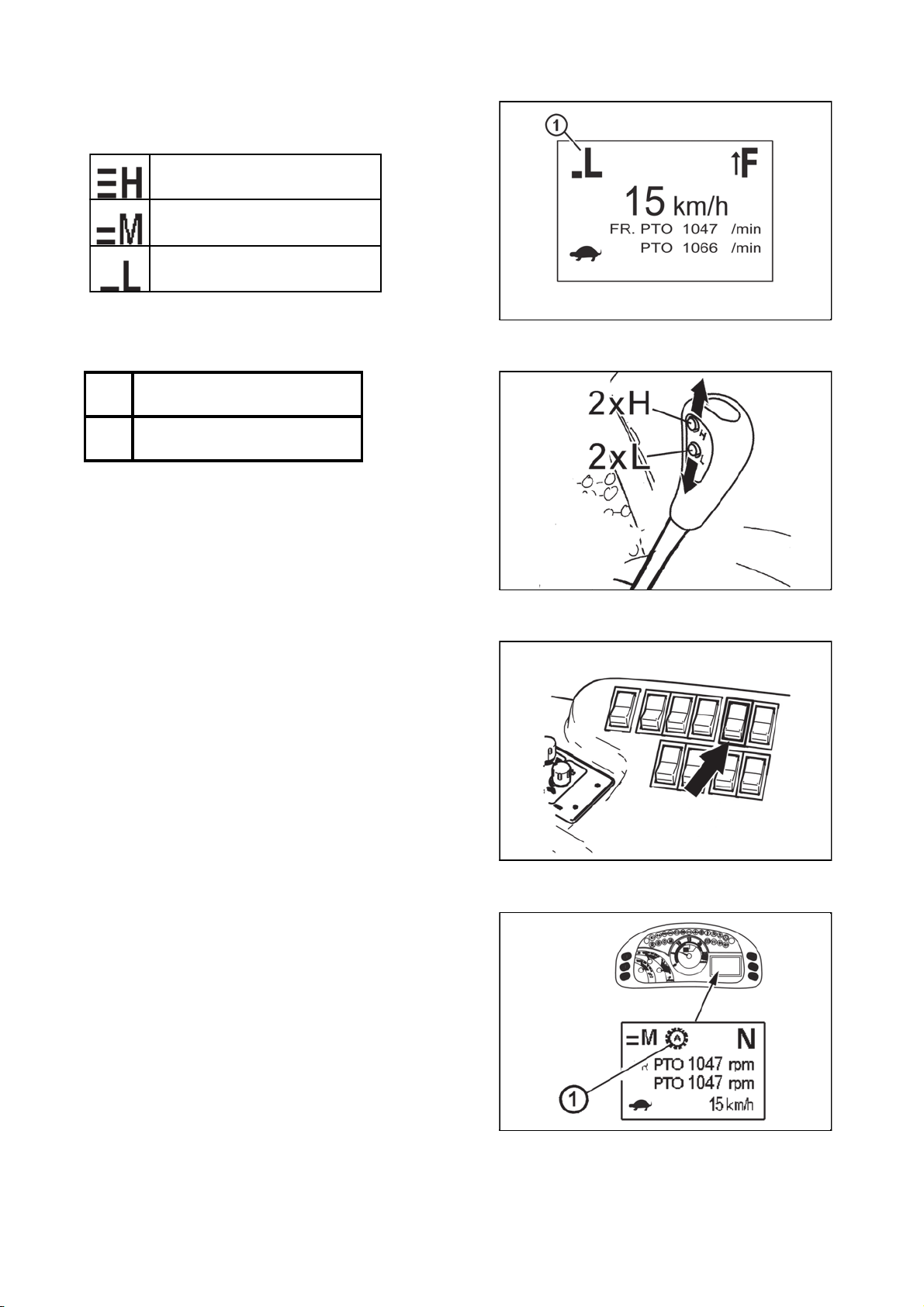
Signalization of multiplier functio
n
DRIVING OPERATION
60
60
Individual engaged gears of multiplier are signalized by
a sign (1) in the left upper corner of the display.
The highest gear (the fastest)
Middle gear
Lowest gear (the slowest)
Increasing, decreasing the travel speed by two gears
2xH Increases the travel speed by
two gears
2xL Decreases the travel speed by
two gears
FHD14N046
Multiplier preselection switch
Multiplier pre-selection switch is located on the control
panel on the right rear mudguard. Engaging the switch is
signalized by a lit symbol on the switch.
If the preselection switch is offthe gears of multiplier can
be engaged by buttons on the gear shifting lever
If the preselection switch is on (b) the gears of multiplier
are shifted automatically depending on engine revolutions
according to pre-saved values.
Multiplier pre-selection signalization
The switch of multiplier reselection switch is signalized by
a sign (1) on the display of dashboard.
FH12N054
FHD14N052
FHD14N047

Automatic multiplier shiftin
g
DRIVING OPERATION
61
61
The system of automatic multiplier shifting is switched by multiplier pre-selection switch on the dashboard. If
the multiplier pre-selection switch is on (control on the switch is lit), the gears of multiplier are shifted
automatically depending on the engine revolutions according to preset values (engine revolutions). The
system of automatic multiplier shifting is not dependent on the engaged speed gear. With engaged multiplier
pre-selection switch, it is possible to turn the engine off and start and the saved values (engine revolutions)
do not change. The values for automatic multiplier shifting are read always when the pre-selection switch is
off, with tractor drive with engine revolutions higher than 700 rpm, with travel speed higher than 2 km/h.
When meeting the previous conditions, the system will remember
a - Engine revolutions with last use of L button on gear shifting lever for automatic shifting of multiplier gears
for lowering the travel speed
b - Engine revolutions with last used of H button on gear shifting lever for automatic engagement of gears of
multiplier for increasing the travel speed
The difference between the engine revolutions for a and b must be greater than 250 rpm
Example of use:
We are driving with a tractor with multiplier pre-selection off with multiplier shifted to M gear, with engine
revolutions of 1,600 rpm we press L button on the gear shifting lever, by this we shift the torque multiplier to
L gear, now we increase the engine revolutions to 1,900 rpm and we press H button on the gear shifting
lever, by this we shift the torque multiplier back to M gear. We continue driving with the tractor. Now we turn
on the multiplier pre-selection switch on the dashboard. From this time, the automatic multiplier gear shifting
system shifts gears of torque multiplier without any intervention of the driver in the following way:
a - With the drop of engine revolutions under 1,600 rpm automatically shifts the multiplier to lower gear
(lowering travel speed)
b - When increasing the engine revolutions above 1,900 rpm, the multiplier automatically shifts to a higher
gear (increasing the travel speed)
The values 1,600 and 1,900 engine revolutions necessary for automatic multiplier shifting used
in this example are purely informative, in practice the number of revolutions is set by the driver
according to the specific use of tractor.
With multiplier pre-selection on, it is possible to shift the multiplier gears also manually on a gear shifting
lever, but only within the range of set values (engine revolutions); i.e. in the example presented in the range
of revolutions from 1,600 to 1,900 rpm, when reaching the saved revolutions for automatic shift of multiplier
gear the multiplier is automatically shifted without driver´s intervention. In this case (multiplier pre-selection
switch on), manual shifting of multiplier by buttons on gear shifting lever does not influence the values
(engine revolutions) that are saved in the system of automatic multiplier shifting. After turning the multiplier
pre-selection on the dashboard off (the control on the switch is not lit) it is possible to shift the torque
multiplier gears only manually by buttons on gear shifting lever.
Beware!
With tractor travel, when the pre-selection multiplier switch on the dashboard is off, the system of automatic
multiplier selection keeps on reading the values (engine revolutions) with every use of H or L buttons use on
gear shifting lever. After switching the multiplier pre-selection switch, the system of automatic multiplier
shifting uses the last read value (engine revolutions) i.e. values read with last usage of H and L buttons on
the gear shifting lever with multiplier pre-selection off.
Recommendation
fore switching the switch of multiplier on the da
Be
H and L buttons (once by H button and once by L button) on gear shifting lever with requested engine
revolutions. The values (engine revolutions) will be saved and after subsequent engagement of the multiplier
pre-selection switch on dashboard, the system of automatic multiplier shifting will automatically shift multiplier
gears according to these engine revolutions
With multiplier pre-selection switch on, in case of release of travel clutch, for example with gear shifting,
stopping and subsequent dead start of tractor or while using reversing, the system of automatic shifting of
multiplier sets an applicable multiplier gear with subsequent switch of travel clutch.
shboard, do the manual shift of multiplier gear when using
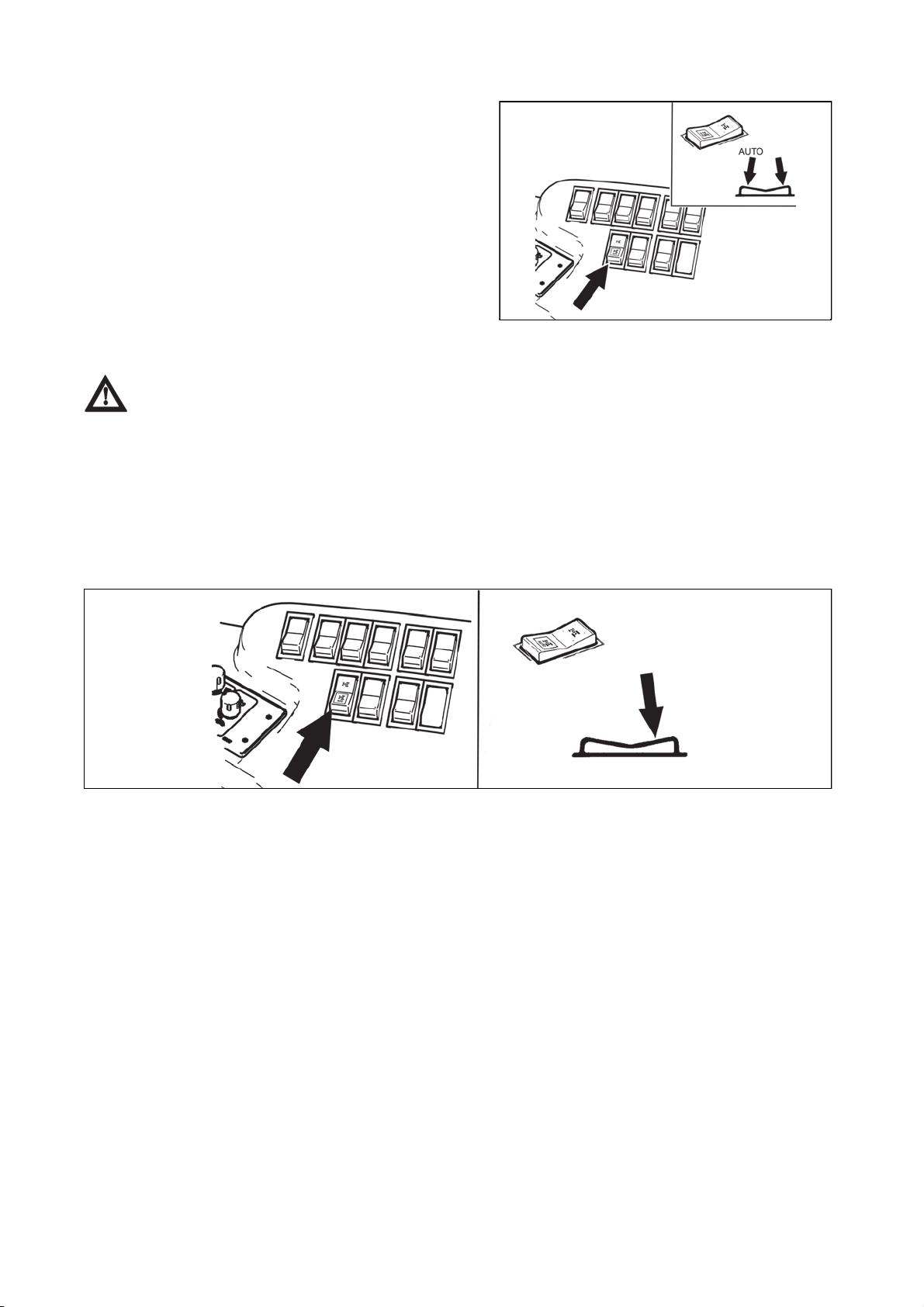
Front drive axle control
DRIVING OPERATION
62
62
Front drive axle control button is placed on the panel on
the right rear mudguard.
By pressing the upper part of the button, the function
manual mode is engaged - front drive axle control.
By pressing the lower part of the button (auto symbol) the
function automatic mode - front drive axle control is
engaged.
With the tractor at stand-off (tractor braked, engine
stopped, the key of switchbox disengaged) front drive axle
drive is off.
After restart of the engine, front drive axle returns to the
mode it was before turning the engine off.
FHD14N031
Driving with engaged front axle drive
Use front drive axle when rear wheels slip to increase the tractor´s traction. It is not
recommended to drive with engaged front axle drive on the roads or hard surfaces (driving with
engaged front axle drive causes increased wear of front tyres).
Permanent engagement of front drive axle is admitted if there is an agricultural machine or tools mounted to
the tractor from the front. This condition is listed in instructions manual of an applicable machine. The
-1
maximum permitted speed of these sets is 15 km.h
.
Manual Front drive axle control
FHD14N032
Engagement of front drive axle in manual mode is done by pressing a button which returns to its initial
position after release. The disengagement of front drive axle is done by repeated pressing of the button. The
engagement of front drive axle is signalized by a lit symbol on the switch and a symbol on the display of the
dashboard.
Automatic disconnection of front drive axle
When exceeding travel speed of 20 km/h, the drive of front drive axle is automatically disconnected.
Automatic disconnection of the drive is signalized by blinking of control in a switch. After switching off of the
blinking control, front drive axle is automatically disconnected.
With the drop of travel speed under 20 km/h, front drive axle can be connected by a repeated depression of
a button.
With speeds higher than 20 km/h, the drive of front drive axle can be connected by repeated depression of
a blinking button.Front axle drive is engaged permanently by a long pressing of a button (app. 3s) for the
whole period of tractor drive (without disengagement of automatics). Front axle drive remains engaged also
when overcoming travel speed of 20 km/h. By putting the tractor at standstill, front axle drive is disengaged
automatically.
The switch from manual to automatic mode can be done after the disengagement of manual mode.

Automatic front drive axle control
y p
.
DRIVING OPERATION
63
63
FHD14N033
Engagement of front drive axle in automatic mode is done by pressing a button which returns to its initial
position after release. The disengagement of front drive axle is done by repeated pressing of the button.
Engagement of front drive axle is signalized by a lit symbol on the switch and a symbol on the display of
dashboard.
Automatic mode of front drive axle control
When automatic front drive axle control is on, the drive of front axle connects automatically, if the angular
front wheels displacement is smaller than 15° and travelling speed is lower than 20 km/h,
When you exceed the angular displacement of front wheels 25° or with travelling speed higher than 20 km/h,
the drive of front axle disconnects. When the front wheels angular displacement change has lower value than
15°, the drive of front axle connects automatically.
If there is a disconnection of front axle drive for the reason of travel speed higher than 20km/h, then the drive
of front axle does not connect automatically with lower travel speed and it is necessary to connect it by
pressing a button.
The switch from automatic to manual mode can be done by pressing the button of manual mode.
Axle lock control of rear and front axle
FHD14N034
Axle lock control button is placed on the panel on the right rear mudguard. Engagement of axle locks is done
by pressing the button which returns to its initial position after release. By pressing the upper part of the
button, manual mode of axle locks control function is engaged. By pressing the lower part of the button (auto
symbol) the function automatic mode of axle locks is on. Axle locks engagement is signalized by a lit symbol
on the switch and a symbol on the display of the dashboard. It applies for mechanical and automatic mode of
axle locks.
Axle locks cannot be engaged if front drive axle drive is not engaged. When engaging both of
the brake pedals, the locks remain switched.
When achieving travel speed which is higher than 15 km/h for the time period of 5 seconds, the axle
locks switch off automatically. This condition is signalized for a time period of 5 seconds before the
axle locks are disengaged by a blinking of the button symbol. If the axle locks were disengaged due
to higher travel speed than 15 km/h, then with a lowered travel speed the axle locks are not engaged
automatically and it is necessary to turn them on by pressing a button.
Axle locks are disengaged by repeatedly pressing a button or by engaging one of the brake pedals. The
switch from manual to automatic mode can be done b
ressing the automatic mode button

Automatic axle lock control of rear and front axle
DRIVING OPERATION
64
64
FHD14N035
The engagement of axle locks of rear and front drive axle in automatic mode is done by pressing a button
which returns to its initial position after release. The disengagement of this function is done by a repeated
pressing of the button.
The engagement of the axle locks is signalized by a lit symbol on the switch and a symbol on the display of
the dashboard.
Automatic mode of axle locks control
Automatic mode of axle locks control lies in disengagement of axle locks if any of the following situations
occur:
1. the angular displacement of front wheels is greater than 15°, if the angular displacement of front wheels
changes to smaller than 15°, axle locks turn on automatically
2. arms of the rear three-point hitch are heaved in a position, in which the PTO shaft clutch is automatically
disconnected (for more see DRIVE OF AGRICULTURAL MACHINES chapter), when lowering the arms of
the rear three-point hitch, the axle locks get engaged automatically
3. travel speed is higher than 15 km/h, with lowered travel speed the axle locks are not engaged
automatically and it is necessary to turn them on by pressing a button
The switch from automatic to manual mode can be done by pressing the manual mode button.
Disengagement of axle locks is to be done by pressing the button auto again or by depressing a brake pedal.
Suspension front drive axle
FHD14N055
Tractors can be equipped with a suspension front drive axle upon request.
Suspension drive axle control buttons (1) and (2) are located on the panel in the area of the right rear
mudguard.
Button (1) serves for setting the suspension mode of front drive axle.
Button (2) serves for height adjustment of the front part of the tractor.
If travelling speed of the tractor is higher than 13 km/h, front drive axle transfers automatically
to automatic mode where the axle is automatically kept in approximately half of the suspension
heave.

Front drive axle suspension mode settin
g
DRIVING OPERATION
65
65
Button (1) serves for front drive axle suspension mode setting.
FHD14N069a
(a) - after pressing the upper part of the button, there is a lock of front drive axle suspension, the front part of
the tractor is lowered to the lowest position. Suspension does not work with the axle and the axle acts as if
there were no suspension. The button is locked in (a) position. Front drive axle suspension lock mode can be
disengaged by switching the button (1) to (b) position.
Use this mode always when working with a front loader.
If a tractor is at stand-off with a button (1) in position (a), with next engine starting the
suspension of front drive axle is locked.
( b ) - middle position of the button, the so-called manual mode. Height adjustment of front drive axle works
in this position by the button (2). Suspension works by the axle.
( c ) - after pressing the lower part of the button, front drive axle goes to automatic mode where the axle is
automatically kept approximately in half of the suspension heave. This mode is signalized by a lit symbol on
the button ( 1 ). Suspension works with the axle. Automatic mode can be disengaged by switching the button
to ( b ) position.
The blinking of the symbol on the button signalizes a failure in the circuit of front drive axle
suspension. The code of failure is displayed on the dashboard display.
Height adjustment of the front part of the tractor
Button (2) serves for height adjustment of the front part of
the tractor. Button (1) must be in the manual mode
position.
FHD14N056

(a) - by holding the upper part of the bottom for a longer
DRIVING OPERATION
66
66
period of time, the front part of the tractor lifts upward after
a certain delay, it is lifting for the time of button holding to
the end position of the suspension.
(b) - by holding the lower part of the button, after a certain
time, the front part of the tractor goes down. It is going
down for the time of holding the button to the end position
of the suspension.
FHD14N057
Diesel particle filter
The exhaust system of a tractor is equipped with
a diesel particle filter which serves for cleaning exhaust
fumes. Solid particles (carbon particles) are collected and
burned in diesel particle filter which originate by burning
diesel.
The activity of diesel particle filter is signalized by a pair of
controls (green and red) on the dashboard. Diesel particle
filter system failures with engine running are signalized by
a lit red control on the dashboard and then with an
acoustic signal.
A short-term turning on of the red control
without a subsequent acoustic signal does not
signalize a failure.
The conditions suitable for diesel particle filter
regeneration are signalized by a lit green control on the
dashboard with engine running. Clogging of diesel particle
filter automatically regenerates the exhaust gases
temperature with higher engine load.
FHD14N058
FH12N056
FH12N074
When operating tractors with engines equipped
with diesel particle filter, avoid long-term operation or
low engine load.

Diesel particle filter - system failures signalizatio
n
DRIVING OPERATION
67
67
Failures in diesel particle system failure are
signalized by a red control lighting up on the dashboard
with engine running and subsequently by an acoustic
signal.
If the failure is not removed, it is signalized with any
following starting of the engine
The code of failure us displayed on a display (1) of the
displaying unit which is accessible after removing the right
cover of the steering console.
The failures are displayed on display (1) in a form of E:
double-figured code of failure
For example: E:36, number 36 representing the code of
failure
If failure is not signalized, operation data of diesel particle
filter system are displayed on the display.
The acoustic signal can be turned off by the button (2). If
the failure has not been removed, the acoustic signal is
active with repeated staring of the engine and can be
turned off again by the button (2).
If the key is in switchbox in 'I' position and the engine is
not started, approximately ten minutes later the diesel
particle filter system starts signalizing a failure. Switch the
key to '0' position and start the engine. The code of failure
on the display E:32 or E:33.
FH12N075
Diesel particle filter failure codes
Failure
Operator´s activity
code E:
11, 12, 21,
22, 23, 31,
34, 35, 37,
38, 41, 42,
51, 52, 61,
62
The tractor can be
worked without any
limitations, after
terminating your work,
contact authorized
service and report the
code of failure.
32, 33, Switch the key to '0'
position and start the
engine.
36 Regenerate diesel
particle filter.

Diesel particle filter regeneration
DRIVING OPERATION
68
68
During the operation of a tractor, diesel particle
filter is clogged by solid particles originating in engine run
when burning fuel. Clogged diesel particle filter
automatically regenerates the temperature of exhaust
fumes with higher load of the engine.
When operating the tractor with low load of the engine ,
e.g. with long-term operation on idle run, there is a partial
clogging of diesel particle filter. This condition is signalized
with the engine run by a lit red control of diesel particle
filter, and followingly also by acoustic signal and on the
display of displaying unit of diesel particle filter by failure
code
E:36
If this situation occurs, increase the load of engine and
continue working until red control of diesel particle filter
switches off and acoustic signal does not stop.
By increasing the engine load, the temperature of exhaust
fumes increases and the solid particles which clog diesel
particle filter burn.
The conditions suitable for diesel particle filter
regeneration are signalized by a lit green control on the
dashboard.
Depending on the temperature of exhaust fumes and the
degree of diesel particle filter clogging, regeneration can
take up to thirty minutes.
FH12N076
When regeneration is achieved, notification
information signalization goes out (error 36). If this
signalization does not go out, repeat this procedure. If
it still does not go out, you need to address an
authorized service.
Increased load of engine shall be work with
a tractor at higher engine revolutions(1 800 RPM) with
connected tools, power intake via PTO shaft or outer
hydraulic circuit.
Manual brake - signalization
If the tractor is not braked by a manual brake, a warning is
displayed on a display (a letter P in a circle) and at the
same time there is a sound signal.
This situation occurs in two cases
a - a tractor unbraked by a manual brake with engine
running and a driver leaves its seat
b - a tractor unbraked by a manual brake standing with
engine off and the key is shifted in '0' position.
Brake the tractor with a manual brake.
FH12N039

Driving up the slope
p
.
DRIVING OPERATION
69
69
Shift from higher to lower gear in time when
driving up the slope not to have a drop in engine
revolutions under 800 revolutions per minute, do not
allow a drive leading to the engine stop due to
overload.
Driving down the slope
Driving down the slope without engaged gear
speed is forbidden. If you travel from a longer slope,
shift the lower gear speed the steeper the slope is.
Shift the lower gear speed before the slope, if
ossible
Note: The gear speed with which you easily overcome an
ascent, you will also successfully manage descent.
F11N020
Foot brakes
They are disc, wet, hydraulically controlled, doublepedalled with automatic pressure equalizer.
When driving on the road, both pedals must be
connected by valve. Use disconnected pedals for
braking right or left wheel only when working in
terrain or on the field.
Note: When going down a steep slope with a trailer or
articulated trailer equipped with air or hydraulic brakes, it
is necessary to brake by a foot brake from the beginning
of descend.
When braking with one brake pedal trailer´s
brakes are not active!
Air brakes of trailers and articulated trailers
Air brakes of trailers (articulated trailers) control and
control of tractor brakes is done so that braking effect of
both vehicles is synchronized.
Working pressure is set by pressure regulator to 740 ± 20
kPa. When the pressure drops below 550 - 40 kPa bypass valves, puts auxiliary devices out of operation
(differential lock, engagement of front drive axle).
F11N021
FHD14N086
F11N022

Warning signalization of air pressured drop
p
DRIVING OPERATION
70
70
Air pressure drop below 450 kPa is signalized by alit red
control bulb placed on a dashboard.
Tractor with braked trailer or articulated trailer
with pressured drop in air pressure system under 450
kPa must not continue in transport if there is not
increase in air pressure.
One-hose and two-hose brakes
1. clutch head of one-hose brakes
2. clutch heads of two-hose brakes
Clutch heads after disconnection or without
a connected trailer, articulated trailer must be closed
by a valve.
F11N023
One-hose brakes
Valve is marked with a black colour.
Operating pressure is adjusted with the control valve at
600 ± 20 kPa.
When connecting the trailer (articulated trailer)
with a maximum allowed weight approved for the type
of tractor at stake is a maximum allowed speed of the
set of 30 km per hour! Maximum allowed speed of the
set is defined by maximum allowed speed of the
slower vehicle of the set.
Two-hose brakes
Operating pressure is adjusted with the control valve at
740 ± 20 kPa. Capacity of air tank is 20 l.
The valve of the left head is labelled in yellow (braking
branch), the valve of the right head is labelled in red (filling
branch).
When connecting the trailer (articulated trailer)
with a maximum permitted speed approved for the
type of tractor, the maximum permitted speed of set is
40 km per hour!
Maximum permitted speed of set is given by maximum
ermitted speed of the slower vehicle of the set.
FHD14N061
FHD14N062
FHD14N063

Hydraulic brakes of trailers
DRIVING OPERATION
71
71
FHD14N064
Connect hydraulic brakes of trailer or articulated trailer to the quick couplings marked by an arrow.
Control of hydraulic brakes of trailers (articulated trailers) and control of tractor brakes is done so that the
braking effect of both vehicles is synchronized. Working pressure is derived by oil supplied by non-switched
on/switched off gear pump of hydraulics. Brake valve of the trailer is done by the pressure of brake fluid from
main braking rollers depending on the force effecting on the brake pedal. The pressure on clutch head must
be 12 - 15 MPa with maximum depression of brake pedal. Brake valve of trailer prefers the function of brakes
to the function of hydraulics. If there are shocks when foot brake pedals are depressed in the pipeline of
hydraulic circuit, it is necessary to bleed the hose from the brake valve to the quick coupling.
When driving with connected trailer or articulated trailer, the pedals of foot brake must be
connected and secured by a valve! When braking with one brake pedal, hydraulic brakes of the trailer
are not active.
Connecting and disconnecting quick couplings of trailer hydraulic brakes
When connecting and disconnecting quick couplings, take increased care with regard for
remaining oil which remains in the socket or in the plug of quick coupling. For ecological reasons, it
is necessary to remove this remaining oil after every disconnection of quick couplings with any
textile material.
Stopping the tractor - manual brake
Stop the tractor slowly under standard conditions. Shortly
before stopping:
1. Depress the clutch pedal.
2. Shift the main gear shifting lever to neutral position.
3. With every stopping, secure the tractor against
spontaneous dead start by manual brake.
F11N026

Stopping the engine
DRIVING OPERATION
72
72
After the work of tractor when the engine was fully loaded,
it is necessary to secure its cooling.
1. Before stopping the engine, lower the revolutions to 800
- 1000 revolutions per minute and allow it to run for the
time of approximately 5 minutes.
2. Shift the lever of manual throttle to STOP position.
3. The engine stops after turning the key from 'I' position
to '0' position.
Leaving the tractor
Before leaving the tractor with a safety cabin, do not forget
to remove the key from the switch box in '0' position (in
position 'I' and 'II' the key cannot be pulled out).
Tractor must be secured against spontaneous start:
1. Engine off
2. Braked by manual brake
3. Wheels based by wedges.
Engaging a speed gear does not secure the
tractor from start (clutch is switched off).
Lock the cabin.
FH13N010
Warning signalization of hydrostatic steering failure
Hydrostatic steering pump failure is with oil pressure drop
under 120 kPa behind a pump signalized on a dashboard
by an applicable symbol.
Note: When starting the tractor or with low engine
revolutions, the control may blink, if it switches off after
starting or increasing the revolutions, it is not a failure.
Limiting travel speed
If the tractors are not equipped with electronic revolutions
control (engines Z 1516, Z 1616 a Z 1617) , maximum
engine revolutions are automatically lowered if there is
a danger of exceeding the travel speed of 40km/h. This
function cannot be disengaged.
If the tractors are equipped with engine with mechanical
regulation of rotation speed (engines Z 1506 and Z 1606),
it is prohibited to use rear wheels with tyre dimensions
650/65R38 and higher for these tractors.
FH12N077
F_02_68
FHD14N068
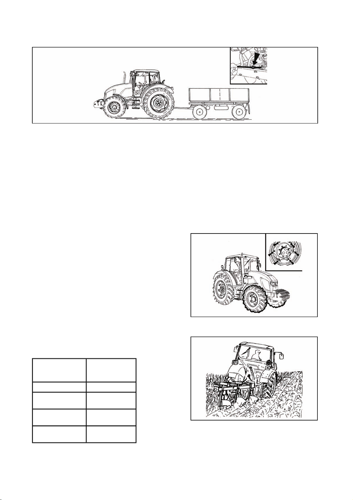
General principles of new tractor run-in in first 100 hours of operation
TRACTOR RUN-IN
7373
F11N030
During first 100 hours of operation:
z Load tractor in a normal way, avoid operation with low or maximum engine revolutions
z Avoid operation under partial loading of the engine
z Avoid excessive idle run operation
z Check oil levels in engine often (during this time increased oil consumption is normal)
z Check screw joints in particular in supporting parts of tractor
z Learned insufficiencies to be removed immediately, you will thus prevent subsequent damage or
endangered operation
z Keep the same procedure also after tractor complete overhaul
In first 10 hours of operation
z perform run-in in traffic
z tighten fastening nuts of front and rear wheels
including connectionbead / rim with prescribed
torque
From 100 hours of operation
After drive in completion you can work with tractor without
limitations.
Recommended
operation
1,400 - 2,300
rpm
revolutions
Idle run revolutions 800 ± 25 rpm
Operation oil
0.2 - 0.5 MPa
pressure
F11N031
Oil pressure with
idle run revolutions
Max. coolant
temperature
min. 0.05 MPa
106°C
E256

NOTES
7474

Before you start, make sure that the technical condition of the tractor corresponds to
p
TRANSPORTATION
7575
requirements for safe operation. When a trailer or implement is attached, check its connection and
roper fixation of the load. Never leave the tractor while it is moving to connect the trailer by
yourself. Also take care of your assistant's safety.
CBM stage quick-adjusting hitch
It is designed for attachment of double-axle trailers or
lighter single-axle semi-trailers. The guiding mouth is
height adjustable. During work with various implements it
may be necessary to adjust the height of the hitch or to
disassemble the entire hitch.
D201
Height adjustment and disassembly of the CBM stage hitch
By moving the control lever in the arrow direction to
position (1) you will release the lever and by moving it
subsequently to position (2) you will retract the locking
pins (3). Now, the stage hitch is released and you can
adjust its height or disassemble it. When you release the
lever from position (2), the locking pins (3) will extend and
the lever will automatically return to the initial position.
Automatic mouth of the CBM stage hitch
When the lever (1) is moved in the direction of the arrow
(a), the pin (2) is retracted to the upper position, which is
signalled by the extended indicator (3), see fig. (A). When
the mouth gets onto the shaft lug, the pin will automatically
slide into the lug of the connected trailer. You can lower
the hitch pin (2) manually by moving the lever (1) in the
arrow (b) direction. The insertion of the pin is signalled by
the retracted indicator (3), see fig. (B).
After the attachment of the trailer you must
always check whether the indicator (3) is retracted in
accordance with fig. (B).
Modular system of hitches for trailers and semi-trailers
Module types:
Fig. (B) - Swinging draw-bar console
Fig. (C) - Swinging draw-bar console with a fixed pin
Fig. (D) - Console with a ø 80 ball
Disassembly, fig. (A):
1 - Remove the locking screw (1).
2 - Secure the module against sinking, release and
disassemble the pins (2).
3 - Slide the module out of the console downwards.
D202
E304
Do the assembly in the reverse order.
D204
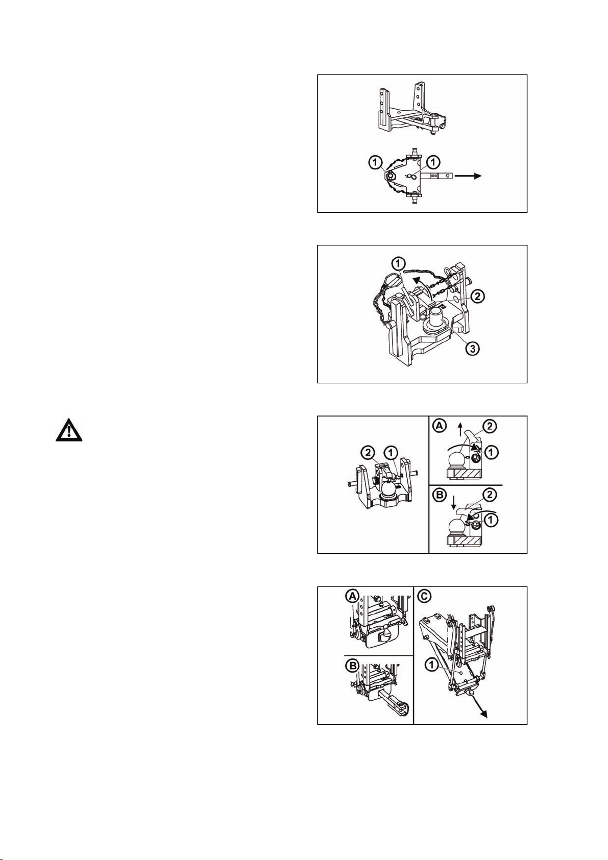
Swinging draw-bar console module
TRANSPORTATION
7676
The swinging draw-bar console module is located in the
stage hitch console.
Swinging draw-bar
Disassembly:
1 - Release and remove the pins (1).
2 - Slide the swinging draw-bar out in the arrow direction.
Do the assembly in the reverse order.
Swinging draw-bar console with a fixed pin module
Perform the assembly and disassembly of the swinging
draw-bar in accordance with the 'Swinging draw-bar'
chapter.
Connecting the shaft lug to the fixed pin (3):
1 - Release and remove the pin (1).
2 - Lift the locking wedge (2) in the arrow direction.
3 - Connect the shaft lug to the fixed pin (3):
4 - Return the locking wedge (2) to the original position
and secure it with the pin (1).
D205
Console with a ø 80 ball module
The console with a ø 80 ball is only used to
connect semi-trailers with a hitching device designed
for a ø 80 ball.
Releasing the hitch, fig. (A):
By moving the lever (1) in the arrow direction you will
remove the locking wedge (2).
Locking the hitch, fig. (B):
By moving the lever (1) in the arrow direction you will
retract the locking wedge (2).
Hitch for a single-axle CBM semi-trailer
The hitch for a single-axle semi-trailer may be equipped
with a hook (A) or with a swinging draw-bar (B).
Replacing the hook with the swinging draw-bar (C):
1 - Lower the hitch.
2 - Release and remove the pin (1).
3 - Remove the hook in the arrow direction.
Install the swinging draw-bar in the reverse order.
D206
D207
D208
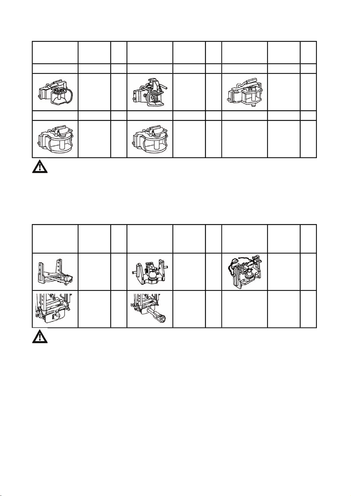
TRANSPORTATION
7777
Maximum permissible vertical static load of hitches for trailers and semi-trailers
Hitch type Permissible
vertical
static load
Hitch class C
2,000 kg
Hitch class D2 Hitch class D3
2,000 kg
The maximum weight of an aggregated braked trailer or semi-trailer must not exceed the value
specified on the data plate of the tractor and the value specified in the technical certificate of the
tractor. The maximum permissible speed of the set results from the maximum permissible speed of
the slower vehicle in the set.
Hitch of class C: max. weight of the trailer 6,000kg.
Hitch of class D2: max. weight of the trailer 14,000kg.
Hitch of class D3: max. weight of the trailer 20,000kg.
Hitch type Permissible
vertical
static load
736 kg
3,000 kg
Hitch
Hitch type Permissible
pin
Ø
31
mm
43
mm
Hitch
Hitch type Permissible
pin
(ball)
Ø
31
mm
47
mm
vertical
static load
2,000 kg
2,000 kg
vertical
static load
2,000 kg
1,200 kg
Hitch
Hitch type Permissible
pin
Ø
38
mm
50
mm
Hitch
Hitch type Permissible
pin
(ball)
Ø
80
mm
31
mm
vertical
static load
2,000 kg 28
vertical
static load
Fixed pin
2,000 kg
Hitch
pin
Ø
mm
Hitch
pin
(ball)
Ø
44.5
mm
The maximum weight of an aggregated braked trailer or semi-trailer must not exceed the value
specified on the data plate of the tractor and the value specified in the technical certificate of the
traktor. The maximum permissible speed of the set results from the maximum permissible speed of
the slower vehicle in the set.

NOTES
7878

Before attaching of an implement, driven by means of the tractor PTO shaft, check the speed
y
gag
DRIVE OF AGRICULTURAL MACHINERY
7979
compatibility of both, it means tractor PTO shaft and implement driven shaft (540 rpm or 1,000 rpm).
Different PTO speed values may cause serious damages and injuries.
Work with PTO shaft
1. When working with PTO shaft mind that all the covers are duly fixed.
2. After completing the work, always mount the cover of PTO shaft back.
repairs or cleaning of aggregated machines parts driven by PTO shaft to be done only with the
3. An
engine at halt and PTO clutch disengaged.
4. Before starting an aggregated machine driven by PTO shaft, make sure that there are no
unauthorized personnel near, there is a risk of injury.
Controlling the front and rear PTO shaft
The switches and buttons for the front and rear PTO
shafts are located on the panel on the right rear
mudguard.
1. Switch for selecting revolutions of rear PTO shaft.
2. Switch for automatic disengagement of rear PTO shaft
clutch.
3. Switch for rear PTO shaft.
4. Switch for front PTO shaft.
FHD14N009
Rear PTO shaft revolutions preselection lever
FHD14N006
The tractor may be equipped with one of two systems of rear PTO shaft revolutions preselection. The system
used in the tractor is marked on the label placed by rear PTO shaft revolutions preselection lever.
1. Standard and economical independent revolutions of rear PTO shaft - label (1)
2. Dependent and independent revolutions of rear PTO shaft - label (2)
Rear PTO shaft revolutions preselection lever (3) is located on the right side of driver's seat.
Independent rear PTO shaft revolutions - number of revolutions is dependent on the number of engine
revolutions.
Dependent rear PTO shaft revolutions - number and the direction of revolutions is dependent on the
ed gear and reversing lever position.
en

(C)
DRIVE OF AGRICULTURAL MACHINERY
8080
Standard and economical independent revolutions of rear PTO shaft
FHD14N007
The system used in the tractor is marked on the label placed by rear PTO shaft revolutions preselection
lever.
This system has only independent revolutions of rear PTO shaft.
A - Standard PTO shaft revolutions engaged
N - Neutral position (rear PTO shaft end-point can be spun freely)
B - Economical revolutions of PTO shaft engaged
With engaged standard PTO shaft revolutions (A), one can engage 540 or 1000 revolutions of rear PTO
shaft on the right side of the cab column by the revolutions selection switch.
With engaged economical PTO shaft revolutions (B), the switch of rear PTO shaft revolutions preselection on
the right column of the cab can be used to engage 540E or 1000E rear PTO shaft revolutions.
The lever is placed on the right side of driver's seat. After shifting the lever, it is necessary to lift collar in the
direction of the arrow (C).
Dependent and independent rear PTO shaft revolutions
FHD14N008
The system used in a tractor is marked on the label placed by the rear PTO shaft revolutions preselection
lever.
This system has only 540 or 1000 rear PTO shaft revolutions.
A - PTO shaft dependent revolutions engaged
N - Neutral position (rear PTO shaft end-point can be spun freely)
B - Independent PTO shaft revolutions engaged
With engaged dependent (A) or independent (B) rear PTO shaft revolutions (B), the switch of rear PTO shaft
revolutions preselection on the right column of the cab can be used to engage 540E or 1000E of rear PTO
shaft revolutions.
The lever is placed on the right side of driver's seat. For shifting the lever, it is necessary to lift collar in the
direction of the arrow
.

r
DRIVE OF AGRICULTURAL MACHINERY
8181
Facilitating connection of joint shaft of an aggregated machine to the tracto
FH12N002
For facilitating the connection of joint shaft of aggregated machine to a tractor a button (1) placed on
mudguards can be used.
With the engine running and rear PTO shaft switch off, spinning of rear PTO shaft occurs after pressing the
button (1). PTO shaft stops spinning after releasing the button.
Beware: Rear PTO shaft revolutions preselection lever must not be in (N) position or in the position of
a dependent revolution of rear PTO shaft.
When manipulating with PTO shaft by means of buttons (1), the operator must stand beyond
the space of the connected tools not to be caught or injured.
Selection switch of rear PTO clutch revolutions (P.T.O.)
FHD14N010
Shifting rear PTO shaft revolutions is done by a switch (1) The switch is equipped with a mechanical lock (2)
against unwanted switch. When switching the switch, depress the lock in downward direction.
A - 540 rpm
B - 1000 rpm
The change of PTO shaft revolutions - 540 and 1000 per minute to be done only with PTO shaft
at halt! Check that the revolutions of PTO shaft are set accordingly with regard for the connected
tools!

A
gag
A
DRIVE OF AGRICULTURAL MACHINERY
8282
Replaceable end points of rear PTO shaft
The tractor is equipped with six or twenty-one splined
replaceable end point of rear PTO shaft.
Replacement procedure:
1. Use safety ring pliers to demount a safety ring (1)
2. Remove replaceable end point by pulling in the
direction of an arrow (2)
3. Mount the end point in an opposite way, pay increased
attention to the mounting of the safety ring (1)
Replacement of the terminal shall be performed
when the engine is stopped.
Rpm of the output shaft and terminal type shall be
chosen depending on the prescribed rpm of the
coupled mechanism.
-1
Shifting 540 and 1,000 or 540E min
is possible
regardless to the number of splines of the installed
terminal.
Rear PTO switch
E357
FH14N010a
Rear PTO shaft clutch is engaged by switch of rear PTO shaft. After engagement of the switch the shaft
spins.
The engagement of the rear PTO clutch is done by a switch (1) placed on the right column of the cabin. The
switch is equipped with a mechanical lock (2) against unwanted switch. When switching the switch, depress
the lock in downward direction.
After switching the switch (1) from (A) position to (B) position rear PTO shaft clutch is engaged and the shaft
spins.
After switching the switch (1) from (B) position to (A) position rear PTO shaft clutch is engaged and the shaft
stops.
By a subsequent switch of switch (1) from (B) position to (C) position lasting at least three seconds automatic
disengagement of PTO shaft clutch is engaged. After releasing the pressure the switch (1) returns to (B)
positions.
By another depression of the switch (1) from (B) position to (C) position this function is disengaged.
- rear PTO shaft clutch disengaged
B - rear PTO shaft clutch en
utomatic disengagement of PTO shaft clutch
C -
ed
Check that the PTO shaft revolutions are set properly with regard for the connected tools!

DRIVE OF AGRICULTURAL MACHINERY
8383
Engaging rear PTO shaft - Independent revolutions
The number of PTO shaft revolutions is dependent on the
number of engine revolutions.
With engine running:
1. Select applicable operation mode PTO shaft revolutions
preselection lever.
2. Select applicable revolutions by switch of selection of
rear PTO shaft (1) revolutions.
3. Rear PTO shaft is set into operation by switching the
switch of rear PTO shaft (3).
Engagement of rear PTO shaft is signalized by the display
of the number of rear PTO shaft revolutions on the display
of the dashboard.
FHD14N012
Engagement of rear PTO shaft is signalized by the display
of the number of rear PTO shaft revolutions on the display
of the dashboard.
If the aggregated machine allows it, engage the
rear PTO shaft with minimum revolutions of 1500 rpm.
FHD14N013
FHD14N014

DRIVE OF AGRICULTURAL MACHINERY
8484
Engagement of rear PTO shaft - dependent revolutions
The number and the direction of the revolutions are
dependent on the engaged gear and the position of
reversing lever. The position of reduction lever does not
have any influence on the number rear PTO shaft
revolutions in dependent revolution mode.
With engine running:
1. Rear PTO shaft dependent revolutions are selected by
PTO shaft revolutions preselection lever.
2. Rear PTO shaft switch (3) is not functional in this mode.
3. Select applicable revolutions by rear PTO shaft
selection switch (2).
4. Engage gear by the main gear shifting lever and the
direction of drive by reversing lever. When tractor drives
off, rear PTO shaft also spins.
Automatic PTO clutch disengagement is not
functional in this mode.
FHD14N012_1
Automatic disengagement of PTO clutch
FHD14N015
The function of automatic disengagement of the PTO clutch means that with PTO shaft engaged after lifting
the arms of rear three-point hitch, the rear PTO clutch is disengaged automatically and the shaft comes to
a halt, after subsequent lowering or arms of three-point hitch, the rear PTO shaft is automatically engaged
and the shaft spins provided that the direction of drive is engaged by reversing lever and the tractor has
travelling speed of at least 0.3 km/h.
By switching the switch from (A) to (B) position, the rear PTO clutch is engaged. By pressing the switch from
(B) position to (C) position that lasts at least three seconds Automatic disengagement of PTO shaft clutch is
engaged. After releasing the pressure, the switch (1) returns to (B) position.
By another depression of switch (A) from (B) position to (C) position, this function is disengaged.
Activation of Automatic disengagement of PTO shaft clutch function is signalled by a symbol (D) displayed
on the display of dashboard.

DRIVE OF AGRICULTURAL MACHINERY
8585
Setting automatic disengagement of PTO shaft clutch - display description
FHD14N016
Display the third display on dashboard by gradual depressing of (A) button.
These values are displayed on the display:
H-LIMIT- position of arms of three-point hitch at which disengagement of rear PTO shaft clutch
ACTUAL- current position of arms of three-point hitch
L-LIMIT- position of arms of three-point hitch at which engagement of rear PTO clutch occurs
The number with individual items has only informative value.
Automatic disengagement of PTO shaft clutch - return to basic setting
Basic values set by the manufacturer are:
H-LIMIT - 55
L-LIMIT - 45
By pressing the button (B) basic values are set on dashboard with displayed display.

y
DRIVE OF AGRICULTURAL MACHINERY
8686
Setting automatic disengagement of PTO shaft clutch
FHD14N017
Setting automatic disengagement of PTO shaft clutch is done with standing tractor with started engine, with
disengaged PTO shaft clutch switch and reversing lever under the steering wheel in neutral position.
Display the third display on dashboard by gradual depression of (A) button.
Setting H-LIMIT position
1. Set the arms of three-point hitch to a position of the required disengagement of rear PTO shaft clutch.
2. Press (C) button on the dashboard. By this a new value is saved and the number by H-LIMIT item
changes and equals to ACTUAL value.
Setting L-LIMIT position
1. Set the arms of the three-point hitch to the position of required engagement of rear PTO shaft clutch.
2. Press (D) button on the dashboard. By this a new value is saved and the number with L-LIMIT item
changes and equals to ACTUAL value.
The number by H-LIMIT item must be always greater at least by 10 than the number by L-LIMIT item, or the
new value will not be saved.
Beware! When setting the position of arms of automatic disengagement of rear PTO shaft
clutch outside basic values set by manufacturer not bearing any liability for damage incurred from
this setting.
Work with automatic disengagement of PTO shaft clutch
Switch automatic disengagement of PTO shaft clutch by (A) switch with tractor at standstill with engine
running. Switching automatic disengagement of PTO shaft clutch is signalized by (B) display on the display
of the dashboard.
After switching the function with a switch (A), the rear PTO shaft is at standstill; this is signalized by blinking
of (B) symbol on the display of the dashboard.
Starting rear PTO shaft
Rear PTO shaft spins if the arms of three-point hitch are lowered lower than L-LIMIT is set and the tractor
goes at a rate faster than 0.3 km/h. When spinning the rear PTO shaft, the display of symbol (B) on the
displa
stops blinking.
FHD14N018

Stopping rear PTO shaft
DRIVE OF AGRICULTURAL MACHINERY
8787
Rear PTO shaft stops if the arms of three-point hitch are lifted higher than H-LIMIT is set. When stopping
rear PTO shaft, the display of symbol (B) starts blinking on the display.
Restarting rear PTO shaft
For subsequent spinning of rear PTO shaft it is necessary to proceed in accordance with see Starting rear
PTO shaft.
If with Stopping rear PTO shaft also stopping of tractor occurs which lasts for more than three minutes,
there is a blockage of starting rear PTO shaft. (B) symbol is not displayed on the display, control on switch
(A) is blinking and PTO shaft does spin also when meeting the conditions for Starting rear PTO shaft.
If there is a blockage of blocking the starting of rear PTO shaft, it is necessary to switch the switch to (A)
position - off. Then switch the rear PTO clutch again by switch A according to previous articles.
Front PTO shaft
Front PTO shaft is equipped with a solid six or twenty-one
splined end point and it comes only in design of 1,000
revolutions.
Tractor may be equipped with front PTO shaft with varied
direction of spinning:
a - In compliance with the direction
of engine revolutions (standard)
b - Against the direction of engine
revolutions (*on request)
Front PTO shaft control
Engagement and disengagement of front PTO shaft is
done by a switch (4) The switch is equipped with
a mechanical lock (2) against unwanted switch. When
switching the switch depress the lock in the downward
direction.
Front PTO shaft is set into activity by switch of a switch.
The engagement of front PTO shaft is signalized by
displaying the number of revolutions of front PTO shaft on
the display of dashboard.
If the aggregated machine permits, engage
front PTO shaft with min. engine revolutions of 1500
rpm.
F_02_64
FHD14N019
FHD14N020

DRIVE OF AGRICULTURAL MACHINERY
8888
Maximum transferred output
PTO shaft Transferred
output
Front
1000 per minute 90 kW
Rear
1000 per minute full engine output
540 per minute full engine output
1000E per minute 60 kW
540E per minute 60 kW
Drive of machines with greater inertia masses
(crushers, rotary harrows, reaping machines, etc.)
Cardan shaft for drive of these machines must be
equipped with the so called freewheel clutch which
ensures disconnection of torque transfer with retroaction
from the machine on the tractor.
F_02_46
troj

Hydraulic syste
m
HYDRAULIC SYSTEM
8989
The system consists of the inner and outer circuit.
The source of pressurized oil is a gear pump.
Oil is drawn from the common filling of the gearbox and
final drive housing.
Indication of low oil temperature
If the temperature of gear oil is lower than 20°C,
the signal lamp of the pushing filter of gearbox
distributor (1) is flashing.
When the temperature of gear oil is higher than 20°C,
the signal lamp (1) stops glowing.
If the signal lamp (1) is flashing, it is not
recommended to use outer circuits of hydraulics.
F_02_112a
Hydraulic pump
The hydraulic pump cannot be disengaged. When the
engine is running, the pump is in operation.
Pump type Delivered quantity
GHD0 32/12,6L 85 l/min
The pressure generated in the hydraulic system by the
hydraulic pump is limited by a relief valve to 20 MPa.
Control elements placement
Control panel is placed on the right rear mudguard.
1. Electrohydraulics control
2. External hydraulic circuit control
F_02_113a
FHD14N042

Outer hydraulic circuit
HYDRAULIC SYSTEM
9090
The outer circuit supplies pressurized oil to hydraulic
implements connected to the outer outlets of the hydraulic
system terminated with quick-couplers.
The sockets of the rear (A) as well as front (B) quickcouplers have the inner diameter of 12.5 mm and comply
with the international ISO 5675 standard.
FHD14N049
Connecting and disconnecting quick-couplers
When connecting and disconnecting the quick-couplers pay increased attention with regard to
the residual oil that remains in the socket or on the plug of the quick-coupler. For environmental
reasons after every disconnection of quick-couplers this residual oil must be removed with any
textile material.
Quick-couplings with drip collection
On request, dripping system for holding leakage oil can be
installed. Regularly check whether the tank is not full;
dispose of the oil in an environment-friendly way.
External hydraulic circuit controls
1. system activation button
2. joystick activation or front outlets switch button
3. joystick
4. applicable hydraulic circuit controls
5. system status controls
6. pivoting selectors for setting the disengagement of
applicable hydraulic circuit depending on time
7. pivoting selectors for setting the flow of oil of an
applicable hydraulic circuit
FHD14N060
FHD14N051

Controls of external hydraulic circuit descriptio
n
HYDRAULIC SYSTEM
9191
FHD14N053
Control (I) controls the quick couplers (A) and (B) section(I)
Control (II) controls quick couplers (A) and (B) section(II)
Control (III) controls quick couplers (A) and (B) section(III)
Control (IV) controls quick couplers (A) and (B) section(IV)
Quick coupler (0) is directly connected with the area of final house driving and is for return oil from external
hydraulic devices (rotation hydro engines in particular).
If the tractor is equipped with a front three-point hitch, it is controlled with a control(IV) and quick couplers (A)
and (B) section(IV) are not mounted
If the tractor is equipped with front outlets (quick couplers), these are controlled with a control (III) and quick
couplers (A) and (B) section(III) are not mounted
If the tractor is equipped with an auxiliary switchboard for front circuits, front outlets and front three-point
hitch are controlled with a joystick and rear quick couplers (A), , (B) and are mounted.
External hydraulic circuit controls activation
External hydraulic circuit control gets activated with the
engine running by a longer press of a button (1)
(approximately 3 seconds).
Control activation is signalized by a lit symbol on the
button.
Activated control can be deactivated by another press of
the button (1); symbol on the button will go off.
When turning the engine off, the control is deactivated
automatically.
FHD14N050
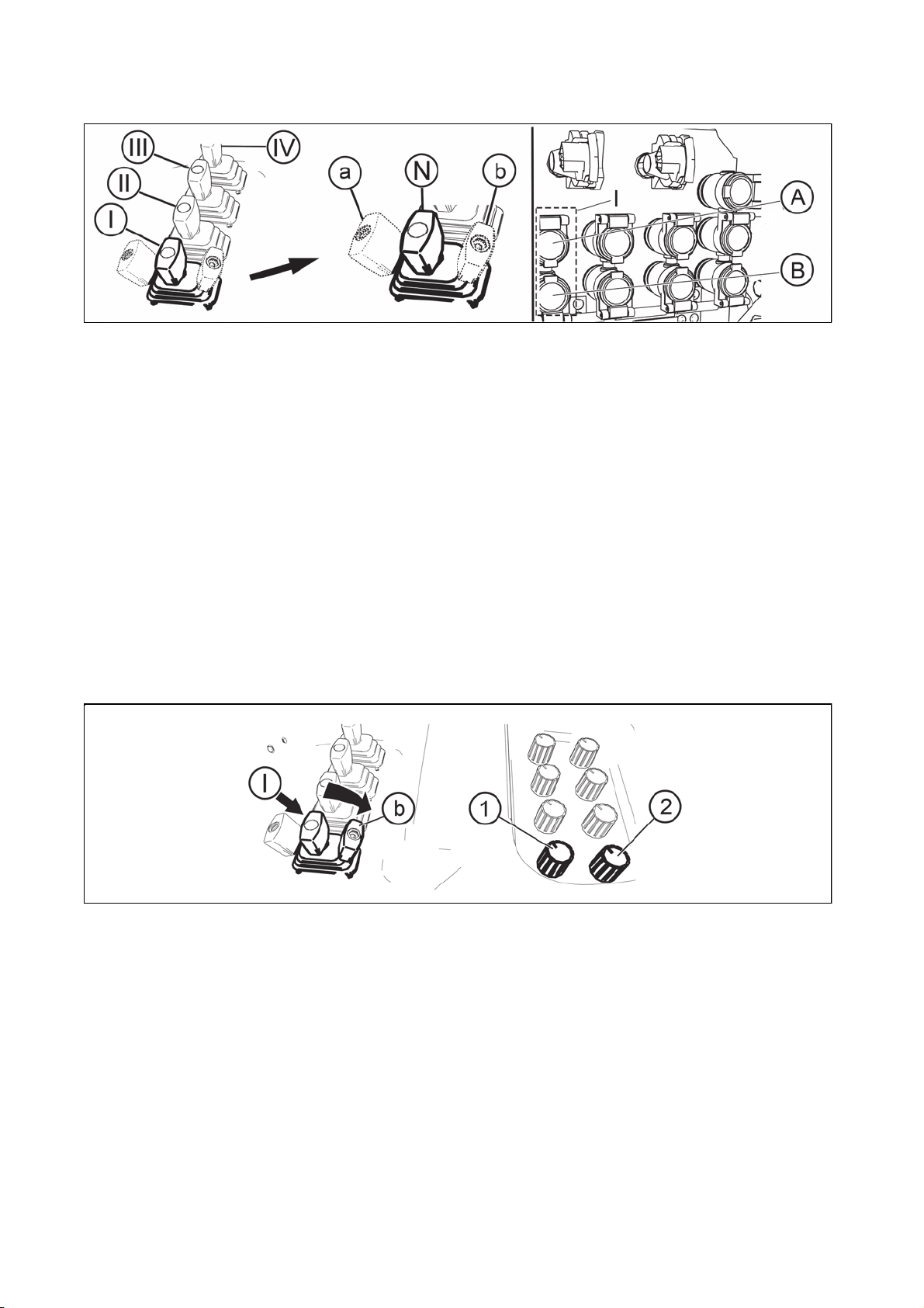
External hydraulic circuit controls functio
n
.
HYDRAULIC SYSTEM
9292
FHD14N065
(N) - Neutral position. Outlets to quick coupler (A) and (B) are closed and oil in the connected hydraulic
device is blocked. Control (I) is locked in this position.
By moving the control from position (N) to the front, there is a gradual growth in the flow of pressurized oil to
a quick coupler (A), quick coupler (B) is connected with the waste. With maximum flow, the movement of
control faces increased resistance. After overcoming the increased resistance you can move the control to
(a) position, where the control is locked.
(a) - Floating position. Both quick couplers (A) and (B) are connected with waste and oil can flow freely in
both directions. Moving the control to (a) position is signalized by a lit control .By moving the control from (N)
position in backward position, there is a gradual increase in the flow of pressurized oil to the quick coupler
(B), quick coupler (A) is connected with the waste. With maximum flow, the movement of control faces an
increased resistance. After overcoming the increased resistance, the control can be shifted to (b) position in
which the control is locked
(b) - a position where there is a stable flow of oil in a quick coupler (B) with an adjustable flow capacity of
10% to 100% of pressurized oil flow and the possibility of the pressurized oil flow time limit (0.5s to
unlimited).
Controls (II), (III) and (IV) have the same functions.
Setting oil flow through quick couplers
FHD14N054
If the control (I) is in (b) position (the position where there is stable flow of oil in the quick coupler (B)
revolving control can be used to:
(1) set a time interval, after it elapses, the flow of pressurized oil to a quick coupler (B) is closed. By control
(1), time interval can be set from 0.5s (backstop of control anticlockwise) to 1 min, at the place of backstop of
control clockwise is a stable, time unlimited flow.
(2) set flow capacity of 10 per cent (backstop control anticlockwise) to 100% (backstop control clockwise) of
pressurized oil flow.
Controls (II), (III) and (IV) have the same functions.
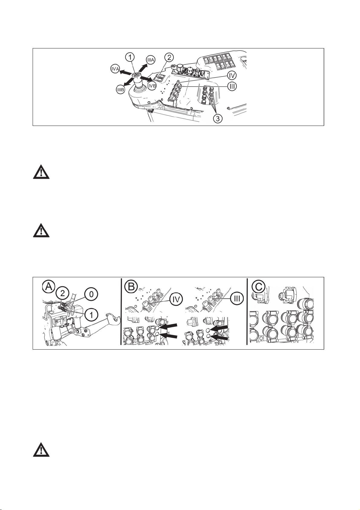
External hydraulic circuits control by means of a joystick
HYDRAULIC SYSTEM
9393
FHD14N048
External hydraulic circuits control, controlled by controls (III) and (VI) can be switched to external hydraulic
circuits control mode by means of a joystick (1). The switch is done by switching the switch (2), which is
equipped with a lock against undesired pressing.
Switch switching (2) is not signalized. Buttons on the upper part of joystick (1) are not
functional
In external hydraulic circuits control mode by means of the joystick( 1 ), the controls ( III ) and ( IV ) are not
functional, their function is taken over by the joystick ( 1 ) including floating positions and stable oil flows with
adjustable flow capacity and also setting the time limit with controls ( 3 ) in individual sections of external
hydraulic circuits.
If the tractor is equipped with an auxiliary switchboard for external hydraulic circuits, the front
outlets and front three-point hitch are controlled with the joystick (1), which cannot be used for
control of external hydraulic circuits controlled with controls (III) and (IV).
External hydraulic circuit front outlets and front three-point hitch
FHD14N071
Front outlets of external hydraulic circuit are located on a panel in the front part of the tractor(A). Quick
couplers (1) and (2) are pressurized; quick coupler (0) is directly connected with the area of final house
driving and is aimed at returning oil from external hydraulic devices.
Standard version of the tractor:
If the tractor is equipped with a front three-point hitch, it is controlled by a control (IV) and the quick couplers
(A) and (B) section(IV) on the rear panel are not mounted (for more see HITCHES chapter).
If the tractor is equipped with front outlets (quick couplers) these are controlled by the control (III) and the
quick couplers (A) and (B) section(III) on the rear panel are not mounted (B).
Tractor in the version with auxiliary switchboard for front hydraulic circuits:
External hydraulic circuit front outlets and front three-point hitch(for more see HITCHES chapter),are
controled with a joystick, on the rear panel there is a complete number of quick couplers (C).
In this case the controls (III) and (IV) cannot be switched to joystick control mode.
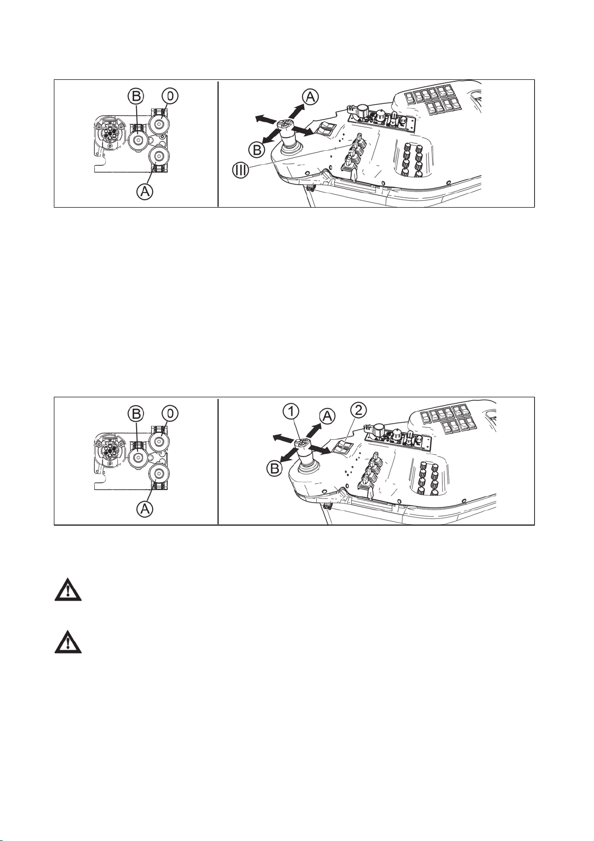
Front outlets of external hydraulic circuit - standard version of the tracto
r
HYDRAULIC SYSTEM
9494
FHD14N074
Front outlets of external circuit are located on the panel in the front part of the tractor. Quick couplers (A) and
(B) are pressurized; quick-coupler (0) is directly connected with the area of final house driving and is aimed
at returning oil from external hydraulic devices.
Front outlets of external hydraulic circuit are controlled by the control(III)
By moving the control from (N) position to the front, there is a gradual growth of pressurized oil flow to the
quick coupler (A), the quick coupler (B) is connected with waste.
By moving the control from (N) position backward, there is a gradual growth in the flow of pressurized oil to
the quick coupler (B), quick coupler (A) is connected with waste.
Floating position function, stable oil flow with adjustable flow capacity and time limit setting as well as the
possibility to switch to the mode of controlling external hydraulic circuits with the joystick is preserved.
Front outlets of external hydraulic circuit - tractor with auxiliary switchboard for front hydraulic
circuits
FHD14N075
Front outlets of external hydraulic circuit are controlled by a joystick (1), a complete number of quick couplers
is on the rear panel.
In this case the controls (III) and (IV) cannot be switched to joystick control mode.
Engagement of auxiliary switchboard for front hydraulic circuits is done by switching the switch (2), which is
equipped with a catch against undesired pressing.
Switch switching (2) is not signalized. The buttons on the upper part of the joystick (1) are not
functional.
By moving the joystick in the direction of the position (A), there is a gradual growth in flow of pressurized oil
to a quick coupler (A), a quick coupler (B) is connected with waste.
By moving the joystick in the direction to position (B), there is a gradual growth in the flow of pressurized oil
to the quick coupler (B), the quick coupler (A) is connected with waste.
Floating position and constant oil flow function is preserved in locked positions.

Connecting machines and tools to external hydraulic circuit
q
.
HYDRAULIC SYSTEM
9595
Connecting rotation hydro engine
If rotation engine is connected to the external hydraulic circuit, it is necessary to always connect the returning
branch to the quick-coupler '0'.
Connecting reversing hydro engine
Reversing rotation hydro engine needs to be connected to quick couplers of one section for its function. In
this case, however, it is necessary that securing vents are included in both of the branches which reliably
limit the pressure peaks with the machine trailing throttle. The waste from these vents is connected to the
uick-coupler '0'

NOTES
9696

Control element functions
ELECTRO-HYDRAULIC SYSTEM
9797
F_02_162
1. Lifting switch
a - Transport, lifting
b - STOP
c - Regularity of lowering (working)
d - Free position, fast sinking- automatic return of lever to (c) position by a spring
2. Blocking (in transport position)
3. Lowering speed
4. Setting the position of lifting device
5. Upper position restriction
6. Smooth setting - of manual control
- automatic control
7. LED - diagnostic
8. LED - lifting
9. LED - lowering
10. Engaging compensator (softening vibrations)
11. LED - softening vibrations engaged
Equipment 'OFF'
Electric installation deactivated with the key of the
switching box. The electronic system is off, the lifting
device is blocked.
F_02_188

ELECTRO-HYDRAULIC SYSTEM
9898
Blocking cancellation
When you switch on the electric installation with the key of
the switching box (I), the lifting device remains blocked
electronically - the lifting and lowering function is
deactivated; on the EHR-B control panel the diagnostic
LED (7) and the vibration dampening LED (11) shortly
light up - the system self-test is in progress. The lifting
LED (8) and the lowering LED (9) are off. After a short
time permanent illumination of the diagnostic LED (7)
indicates the state of EHR-B blocking.
If the diagnostic LED (7) is permanently illuminated, the
control circuits are disconnected.
The engine can only be started if the engine (1)
is in position (b).
The EHR-B electro-hydraulic system is only active when
the engine is started.
Activation of the EHR-B system is only possible when the
lubrication indicator has gone off.
The blocking can only be cancelled (system activated)
with the engine running by moving the lifting lever (1) to
position (a) - short-time switching is sufficient.
By moving the lever (1) to position (c) you will bring the
three-point hitch to the position corresponding to the
element setting, i.e. the current position of controls (4), (5),
(6).
F_02_164
F_02_163
After the activation of the system EHR-B first
for safety reasons limits the lifting speed of the
hydraulic arms. When the hydraulic arms first reach
the selected position, this safety limitation is
cancelled and then the lifting speed of the hydraulic
arms is normal.
Quick sinking
Lever (1) in position (d) - free position. You must hold the
lever in this position; after releasing the lever will return to
position (c) - the system works in accordance with the
setting of controls (3), (4), (5) and (6).
F_02_165

ELECTRO-HYDRAULIC SYSTEM
9999
Transport of implements
Shift the lifting lever (1) to position 'a' and block it with the
moving latch (2).
Blocking the lifting lever (1) by the moving latch (2) in
position (a):
A - Lever movement blocked
B - Lever movement not blocked
When the tractor with an attached implement is
stopped, the implement must be lowered onto the
ground (it must not be left in the lifted position).
Stop position
By moving the lever (1) to position (b) - STOP position you will immediately stop the movement of the three-point
hitch.
F_02_166
F_02_167
Vibration compensator (damper)
F_02_168
It is used during transport of a heavy implement attached to the rear three-point hitch.
After activation of the vibration compensator (10) the arms of the rear three-point hitch sink by approx. 4%,
which allows oscillation of the arms in the range of approx. 8% of the lift. The upward oscillation is always
limited by the position of the upper position limiter (5).
Advantages of active dampening of vibrations during transport of a heavy implement attached to the rear
three-point hitch.
1. Increased operation safety (the steering axle is not unloaded so much
2. Stabilization of the transported implement
3. Reduced dynamic stress of the hydraulic system and the rear three-point hitch
During the adjustment of the hitch for a single-axle semi-trailer the vibration compensator
must be off.
 Loading...