


ZETOR
The supplement to the instruction manual for tractors with 4-cylinder engines, type Z 11741.4C with engines TIER II
and types Z 9641, Z 10641, Z 11441, Z 12441 with engines TIER III, which is hereby presented to you, acquaints
you with operation and maintenance of your new tractor.
Despite the fact that many of you have rich experience with operation of other tractors, please read thoroughly this
manual.
You fan find here many pieces of new information get perfect knowledge how to utilise the tractor with various
works.
When following the given principles of operation and maintenance of the tractor and safe driving, your tractor will
become reliable partner for years.
We wish you thousands of contented worked off hours.
ZETOR
Brno
3

The data on technical specifications, construction, equipment, materials and appearance are valid in time of printing. The
manufacturer reserves the right of changes.
4

CONTENTS
Page Page
Tractors Z 9641, Z 10641, Z 11441, Z 11741.4C, Z 12441, ..... 6
Acquaintance with the tractor............................................... 7
Reverse switches, switches and levers.................................... 7
Switch of torque multiplier preselection (i) ............................... 8
Tiltable steering wheel.............................................................8
Control panel on the cab right column ..................................... 9
Lighter (Z 11741.4C)................................................................ 9
Lighter and 3-pin socket........................................................... 9
Driver’s seat Grammer Maximo............................................. 10
Driving .................................................................................. 11
Moving off .............................................................................. 11
Transport use....................................................................... 12
Multi-storey quick-adjustable hitch CBM................................ 12
Height adjustment and dismantling of the multi-storey hitch
CBM....................................................................................... 12
Automatic guiding device of the multi-storey hitch CBM
>31/03/2007........................................................................... 13
Automatic guiding device of the multi-storey hitch CBM
01/04/2007< ........................................................................... 13
Modular system of hitches for trailers and semi-trailers......... 14
Module of swinging tow bar bracket....................................... 14
Swinging tow bar.................................................................... 14
Module of swinging tow bar bracket with fixed pin................. 14
Module of the bracket with ball ø 80...................................... 15
Hitch CBM for single-axle trailers........................................... 15
Maximum permitted vertical static load of hitches for trailers
and semi-trailers .................................................................... 16
Drive of agricultural machines............................................ 18
Front output shaft Zuidberg.................................................... 18
Maximum transferred power .................................................. 18
Hitches.................................................................................. 19
∗Front 3-point hitch.................................................................19
Front 3-point hitch control.......................................................19
Adjustment of speed of lifting of the front 3-point hitch........... 19
Hydraulic locking of front 3-point hitch....................................20
Working and transport positions of front 3-point hitch ...........20
Working position of the front 3-point hitch..............................20
Electric installation ..............................................................21
Electric set..............................................................................21
Lead battery...........................................................................21
Battery disconnector...............................................................21
Fuse dose (17 fuses)..............................................................22
Fuse dose (21 fuses)..............................................................23
Planned technical maintenance.......................................... 24
Oils for 4-cylinder turbo-charged engines of Z 8641 to Z 12441. 24
Recommended oils for turbo-charged engines according to
ambient temperature..............................................................25
Oils for gearboxes of Z 8641 to Z 12441................................26
Oils for front output shafts Zuidberg....................................... 27
Maintenance instructions.................................................... 28
Refilling of brake fluid.............................................................28
Oil tank of hydrostatic steering...............................................28
Front output shaft................................................................... 28
Essential technical parameters ..............................................29
Technical specifications of engines of tractors Z 11741.4C,
Z 9641, Z 10641, Z 11441, Z 12441.....................................29
Forces (kN) and powers (kW) – engines TIER II....................31
Forces (kN) and powers (kW) – engines TIER III...................32
Speed of the front output shaft Zuidberg................................33
Values for tractors Z 11741.4C and Z 12441 .........................34
Index...................................................................................... 35
5

TRACTORS Z 9641, Z 10641, Z 11441, Z 11741.4C, Z 12441,
Tractors with 4-cylinder engines:
Zetor 9641 Forterra turbo.............. 66 kW
Zetor 106 41 Forterra turbo........... 74 kW
Zetor 114 41 Forterra turbo........... 81 kW
Zetor 117 41.4C Forterra turbo ..... 90 kW
Zetor 124 41 Forterra turbo........... 90 kW
F_02_10
6
ACQUAINTANCE WITH THE TRACTOR
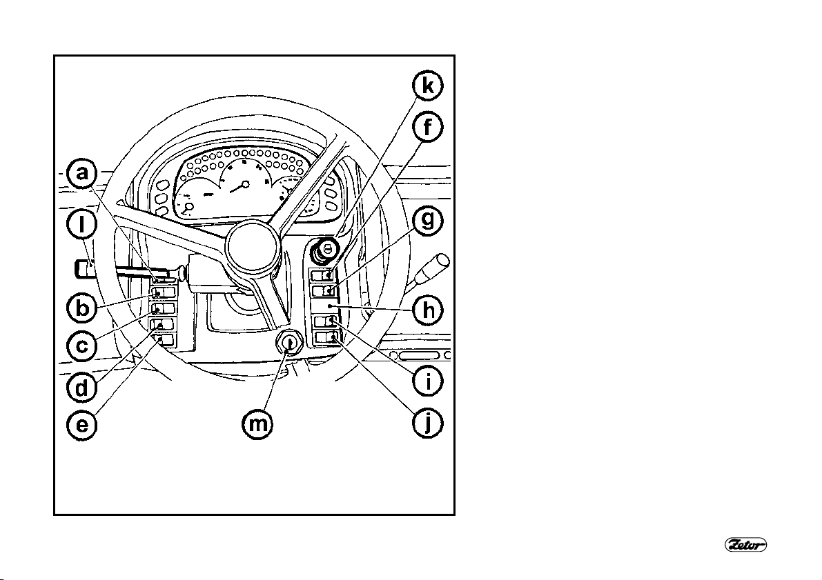
REVERSE SWITCHES, SWITCHES AND LEVERS
a - Switch of lights (off, parking, main)
b - Reverse switch of low beams in the front mask
and working lights in the cab.
c - Switch of the fog light (off/on). Function of the fog
light is indicated by an illuminated symbol on the
switch.
d - Switch of the rear working headlamp (off/on).
Function of the working headlamp is indicated by
an illuminated symbol on the switch.
e - Switch of warning flashlights.
f - Switch of the front driving axle. Switched on front
driving axle is indicated by an illuminated symbol
on the switch.
g - Switch of the beacon (off/on).
h - Free position.
i - Switch of torque multiplier preselection.
j - Pushbutton of the differential lock.
k - Engine stopping device.
l - Reverse switch of direction indicators, low and
high beams and acoustic horn and flash.
m - Ignition switch
F101
7
ACQUAINTANCE WITH THE TRACTOR
D102 F205
SWITCH OF TORQUE MULTIPLIER PRESELECTION (i)
a - Preselection switch off
b - Preselection switch on
Preselection switch on - position (b) - is
indicated by an illuminated symbol on
the switch.
In case the preselection switch is on (b),
each depression of the clutch pedal engages automatically the medium stage pf
the multiplier M – indicator with a symbol
of a turtle is lit on the dashboard (see the
chapter Driving / indication of function of
the multiplier in the ”Instruction manual“).
After release of the clutch pedal the multiplier can be controlled using the
pushbuttons on the speed change lever.
When starting the engine, the
switch must be in position off (a).
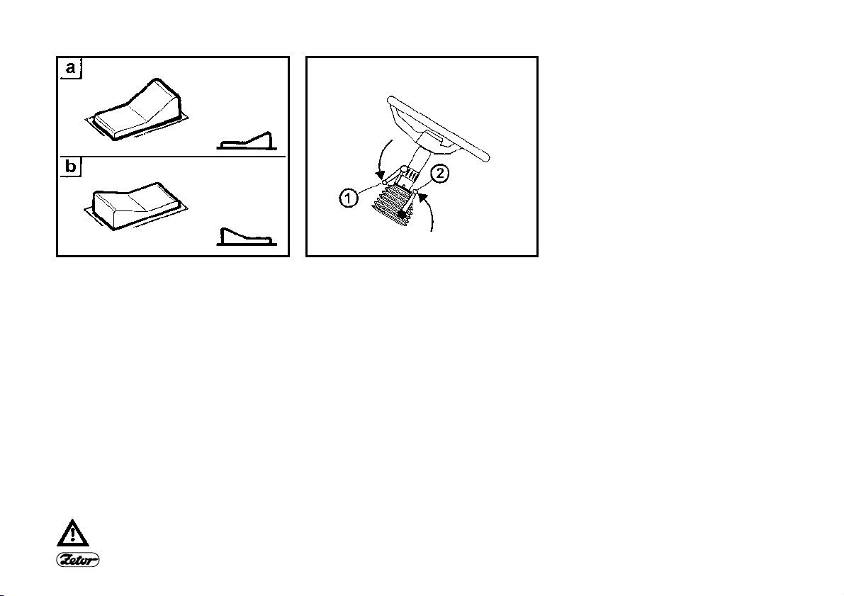
TILTABLE STEERING WHEEL
The steering wheel tilting column enables variable adjustment of the steering
wheel (height and angle adjustment).
Steering wheel height adjustment
Adjustment is carried out by extraction or
retraction of the steering wheel after
unlocking of arrestment by turning of the
lever (1) in direction of the arrow. After
adjustment lock the lever (1) by its tightening against direction of the arrow.
Steering wheel angle adjustment
Adjustment is carried out by tilting of the
steering wheel after unlocking of the arrestment by turning of the lever (2) in direction of the arrow. After adjustment
lock the lever (2) by its tightening against
direction of the arrow.
8
ACQUAINTANCE WITH THE TRACTOR
F_02_156 D103
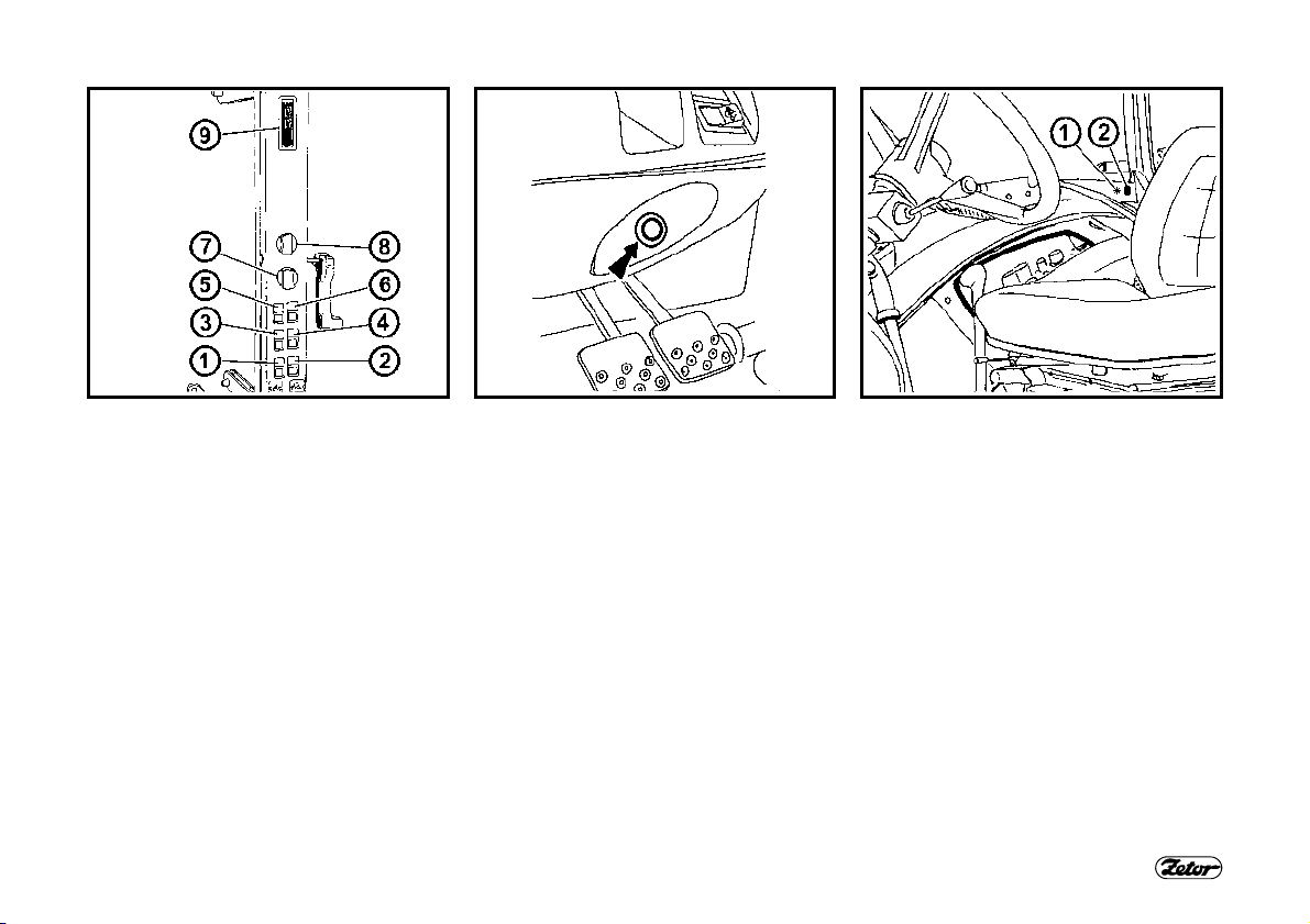
CONTROL PANEL ON THE CAB RIGHT COLUMN
1- ∗Switch of the front output shaft
2- Switch of the rear output shaft
3- Switch of the front working lights on
the cab roof
4- Switch of rear working lights on the
cab roof
5- ∗Switch of heating of the rear-view
mirrors
6- ∗Switch of heating of the rear window
7- Switch of rear wiper
8- 2-position reverse switch of the front
wiper and control of the front wind-
screen washer
9- Cab lighting
LIGHTER (Z 11741.4C)
The lighter is installed on the face of the
driving console, under the dashboard.
After its removal the socket can be used
for power supply of some additional consumers.
9
LIGHTER AND 3-PIN SOCKET
The lighter (1) and 3-pin socket (2) are
installed on the rear right mud guard
panel.
ACQUAINTANCE WITH THE TRACTOR
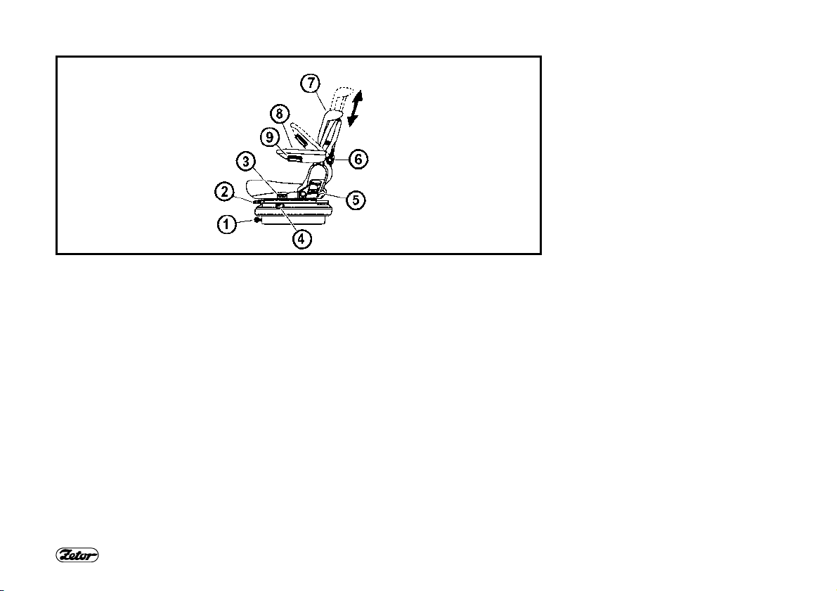
D104
DRIVER’S SEAT GRAMMER MAXIMO
1- Controller of adjustment of seat air hitch according to the driver’s weight
2- Lever of seat longitudinal adjustment (located on the seat right side)
3- Controller of the seat turning device (the seat can be turned by 20° to both sides)
4- Controller of absorption of seat vibrations (tilting of the controller forwards engages
floating position of the seat)
5- Controller of adjustment of the seat backrest
6- Controller of adjustment of the backrest shape
7- Height adjustable backrest (pulling or pus hing in direction of arrow adjusts the back-
rest within 170mm range)
8- Tiltable armrest
9- Controller of adjustment of the armrest (turning of the controller adjusts height of the
armrest)
10
MOVING OFF
1. Select road or reduced gears.
2. Depress the clutch pedal.
3. Move the main shifting lever and reversing lever to neutral position,
switch off the PTO switches on the
right column of the cab.
4. Start up the engine.
5. Adjust speed to 750-800/min-1.
6. Move the reversing lever to the desired driving direction (forward or
backward).
7. Select the desired moving off driving
gear.
8. Increase slightly the engine speed.
9. Grasp the hand brake lever.
DRIVING
F_02_36
10.Release the clutch pedal just up to
the point of drive engagement and
when increasing the engine speed,
continue in releasing of the clutch
pedal.
11.Release completely the hand brake.
12.Move off smoothly and slowly.
Very fast moving off may cause overloading of the driving mechanism, increased fuel consumption, excessive
wearing of tyres and damage to the load.
Moving off using the first gear should
only be used when driving with a heavy
trailer into slope and rough terrain.
When shifting individual gears (1-
4) or reverse (F-R), follow instructions given in this manual for
moving off and shifting. In case of
running engine and tractor in
standstill wait approximately 2
seconds after depressing the
clutch pedal and then engage the
desired gear or reverse.
When shifting in standstill, use
also the foot brake to increase
safety and prevent any unforeseen situations.
11
D201 D202
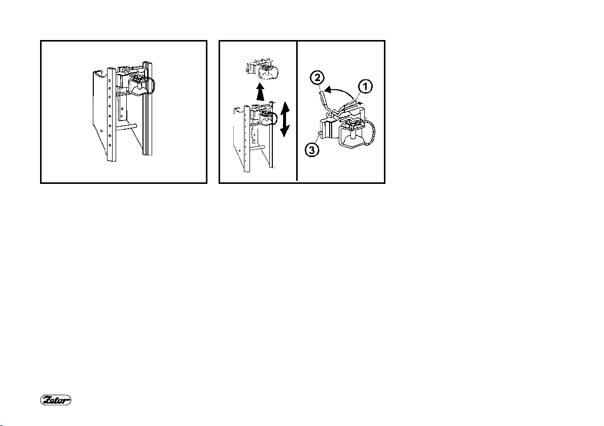
MULTI-STOREY QUICK-ADJUSTABLE HITCH CBM
It is used for connection of double-axle
and light single-axle trailers. The guiding
device is height adjustable. When working with various agricultural machines it
may be necessary to adjust height of the
hitch as desired or dismantle it.
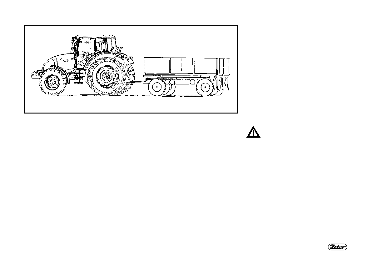
TRANSPORT USE
HEIGHT ADJUSTMENT AND
DISMANTLING OF THE MULTISTOREY HITCH CBM
Unlock the lever by its moving in direction of the arrow to position (1); then
move it to position (2) to engage the arrestment pins (3). This releases completely the multi-storey hitch that can be
adjusted or dismantled.
Release of the lever from position (2)
disengages the arrestment pins (3) and
the lever returns automatically to its initial position.
12

D203 E304
AUTOMATIC GUIDING DEVICE OF THE MULTI-STOREY HITCH CBM >31/03/2007
Moving the lever (1) in direction of the arrow engages the pin (3) in its upper position that is indicated by extracted indicator (4), see Fig. (A).
After sliding the pole eye into the guide
device the pin is inserted automatically
into the eye of the trailer being attached.
The hitch pin (3) can also insert manually
by moving the lever (2) in direction of the
arrow. Insertion of the pin is indicated by
retracted indicator (4), see Fig. (B).
After connecting the trailer, it is
always necessary to check
whether the indicator (4) is retracted as shown on Fig. (B).
TRANSPORT USE
AUTOMATIC GUIDING DEVICE OF THE MULTI-STOREY HITCH CBM 01/04/2007<
Moving the lever (1) in direction of the arrow engages the pin (2) in its upper position that is indicated by extracted indicator (3), see Fig. (A).
After sliding the pole eye into the guide
device the pin is inserted automatically
into the eye of the trailer being attached.
The hitch pin (2) can also insert manually
by moving the lever (1) in direction of the
arrow. Insertion of the pin is indicated by
retracted indicator (3), see Fig. (B).
After connecting the trailer, it is
always necessary to check
whether the indicator (3) is retracted as shown on Fig. (B).
13

D204 D205 D206
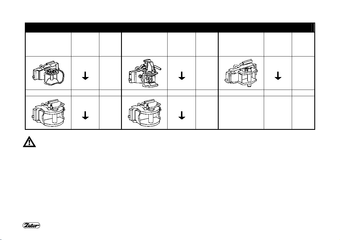
MODULAR SYSTEM OF HITCHES FOR TRAILERS AND SEMI-TRAILERS
Types of modules:
Fig. (B) – Swinging tow bar bracket
Fig. (C) - Swinging tow bar bracket with
fixed pin (piton fix)
Fig. (D) – Bracket with ball ø 80
Dismantling, Fig. (A):
1- Remove the lock screw (1).
2- Support the module, unlock and re-
move the pins (2).
3- Slide the module out of the bracket in
downward direction.
Carry our installation in reverse order.
TRANSPORT USE
MODULE OF SWINGING TOW BAR BRACKET
The module of the swinging tow bar
bracket is mounted in the multi-storey
hitch bracket.
SWINGING TOW BAR
Dismantling:
1- Unlock and dismantle the pins (1).
2- Slide out the swinging tow bar in di-
rection of the arrow.
Carry our installation in reverse order.
MODULE OF SWINGING TOW BAR BRACKET WITH FIXED PIN
Carry out installation and dismantling of
the swinging tow bar as described in
section ”Swinging tow bar“.
Attachment of the pole eye to the fixed
pin (3):
1- Unlock and dismount the pin (1).
2- Lift the locking wedge (2) in direction
of the arrow.
3- Attach the pole eye to the fixed pin
(3).
4- Reposition the locking wedge (2) to
the original position and lock it using
the pin (1).
14

D207 D208
MODULE OF THE BRACKET WITH BALL Ø 80
The bracket with ball ø 80 is used
for attaching of trailers with the
hitch device designed for balls
ø 80.
Unlocking of the hitch, see Fig. (A):
Move of the lever (1) in direction of the
arrow slides off the locking wedge (2).
Locking of the hitch, see Fig. (B):
Move of the lever (1) in direction of the
arrow slides in the locking wedge (2).
TRANSPORT USE
HITCH CBM FOR SINGLE-AXLE TRAILERS
The hitch for single-axle trailers can be
equipped with a hook (A) or swinging tow
bar (B).
Replacement of the hook of the swinging
tow bar (C):
1- Lower the hitch.
2- Unlock and remove the pin (1).
3- Remove the hook in direction of the
arrow.
Carry out installation of the swinging tow
bar in reverse order.
15
TRANSPORT USE
MAXIMUM PERMITTED VERTICAL STATIC LOAD OF HITCHES FOR TRAILERS AND SEMI-TRAILERS
Hitch type
Permitted
vertical
static
load
Hitch
pin Ø
Hitch type
Permitted
vertical
static
load
Hitch
pin Ø
Permitted
Hitch type
vertical
static
load
Hitch
pin Ø
2,000 kg
Maximum weight of the aggregated braked trailer or semi-trailer may not exceed the value indicated on the tractor serial
plate and value given in the technical passport (MOT certificate) of the vehicle. Maximum speed of the vehicle combination is given by the maximum permitted speed of the slower vehicle in the combination.
2,000 kg
31 mm
43 mm
2,000 kg
2,000 kg
16
38 mm
50 mm
2,000 kg
28 mm

TRANSPORT USE
MAXIMUM PERMITTED VERTICAL STATIC LOAD OF HITCHES FOR TRAILERS AND SEMI-TRAILERS
Hitch type
Permitted
vertical
static load
Hitch
pin
(ball)
Ø
Hitch type
Permitted
vertical
static load
Hitch
pin
(ball)
Ø
Hitch type
Permitted
vertical
static
load
Hitch pin
(ball) Ø
736 kg
Maximum weight of the aggregated braked trailer or semi-trailer may not exceed the value indicated on the tractor serial
plate and value given in the technical passport (MOT certificate) of the vehicle. Maximum speed of the vehicle combination is given by the maximum permitted speed of the slower vehicle in the combination.
3,000 kg
31
mm
47
mm
2,000 kg
1,200 kg
80
mm
17
Fixed pin
2,000 kg
44.5 mm

DRIVE OF AGRICULTURAL MACHINES
E356 E358
FRONT OUTPUT SHAFT ZUIDBERG
The front output shaft is equipped with a
fixed 21-groove terminal and speed only
1,000 min
The tractor may be equipped optionally
with a front output shaft with both directions of rotation:
a b -
-1
.
In direction of rotation of the engine (standard)
Against direction of rotation of the
engine (∗ optional)
MAXIMUM TRANSFERRED POWER
-1
Transferred
power
45 kW*
Output shaft
front (Zuidberg)
1,000 min
rear
1000 min-1engine full power
540 min-1engine full power
540E min-1engine full power
*In case of a transfer of power without
any surges, the value may be increased
to 50 kW
18

HITCHES
E461 F_02_209 E463
∗FRONT 3-POINT HITCH
It is designed to attaching of front-carried
agricultural machines and tools according to ISO 8759-2.
When transporting carried tools, it
is always necessary to lock the
hitch in the lifted position hydraulically by valves on the left side of
the tractor, above its front axle.
This hydraulic locking is recommended
even in case that there is not attached
any machine to the 3-point hitch.
FRONT 3-POINT HITCH CONTROL
The hitch is equipped with two singleacting hydraulic cylinders with supply of oil
from the additional hydraulic distributor.
Lifting and lowering is executed using the
additional distributor control lever (1):
Position 6
Position 5
position N
lifting
lowering
locking of hitch
19
ADJUSTMENT OF SPEED OF LIFTING OF THE FRONT 3-POINT HITCH
Before commencement of work with
tools attached to the front 3-point hitch it
is recommended to adjust the throttling
valve (3) so that the time necessary for
lowering of tools from the highest to the
lowest position is 1 to 1.5 sec. When
turning the valve body counterclockwise
(in direction of the arrow) the lowering
speed increases. When adjusting the
valve, the levers of the front hitch valves
shall be horizontal.

HITCHES
E461 E466
HYDRAULIC LOCKING OF FRONT 3POINT HITCH
Hydraulic locking of the front 3-point
hitch can be carried out in any position of
the hydraulic cylinders, using valves in
the front part of the tractor (2).
A
Free position
Valve levers are in horizontal position; the hitch can be controlled
from the cab
B
Locked position
Valve levers are in vertical position; the hitch is locked
The upper lever of the front 3-point hitch
hydraulic lock id fitted with arrestment.
Before moving the upper lever to another
position, unlock the lever by pulling it out
of the hydraulic lock valve body.
Carry out locking or unlocking of
the front 3-point hitch always using both levers!
20
WORKING AND TRANSPORT POSITIONS OF FRONT 3-POINT HITCH
A
Working position of the front 3point hitch
B
Transport position of the front 3point hitch
Change of position of the front 3-point
hitch pull rods:
1. Unlock and remove the pin (1) from
the hole.
2. Lift the arm from position (A) to position (B).
3. Lock the arm by insertion of the pin to
the hole (2) and lock the pin.
Insert only pins into the holes;
never check the holes by fingers!

ELECTRIC INSTALLATION
ELECTRIC SET
Nominal voltage
Grounded minus (-) pole
Battery (1)
12V / 155Ah 12V
Alternator with built-in voltage regula-
tor (2)
14V / 95A
Starter with reducer (3)
12V / 3kW
Vee belts of alternator and water
pump drive
AVX10x1385Laservice
12V
D301 D305 D302
LEAD BATTERY
The lead battery is installed under a
cover on the left side of the tractor, under
the cab footboard.
The battery is accessible after lifting off
the cab footboard.
When lifting off the cab footboard, it is necessary to have
the cab door closed.
1- Remove the screw (1)
2- Lift the footboard in direction of the
arrow.
3- Secure the lifted footboard with a
screw in the footboard hole (2).
4- Remove the safety catch (3).
5- Hold the cover at the lower edge, lift
and remove it.
BATTERY DISCONNECTOR
The battery disconnector (1) is located
on the left side of the tractor, close to the
starter.
a- Battery connected
b- Battery disconnected
When parking the tractor, disconnect the battery using its disconnector (1). This stops permanent
minimum power withdrawal of the
warning lights interrupter (approx.
10mA). In case the tractor is put
aside for a longer period, it is
necessary to recharge the battery
at least every three months due
to battery self-discharging.
21

ELECTRIC INSTALLATION
D303
FUSE DOSE (17 FUSES)
It is accessible after removal of the steering console left cover.
The fuses (1) are knife type and should
be replaced only for fuses with the same
rating. In case of repeated blowing seek
the nearest service shop.
The fuse of glowing (2) is a strip type
with rating 80A.
∗ - Optional accessories.
1) Used with installation of independent control of working lights on the
cab roof.
Location of the fuses in the
fuse dose
22
Pos. Fuse
rating
1 15A Interrupter of warning lights
2 15A Horn
3 15A Front driving axle, differential
4 15A High beams with indicator
5 15A Left side marker lights
6 15A Right side marker lights
7 15A Right low beam
8 15A Left low beam, indicator of light
9 15A Front and rear wipers, washer
10 15A Heating fan, relays “5“ and “6“
11 15A Reserve
∗12
∗13
∗14
∗15
16 1) 15A Lights in the tractor roof 1)
17 80A Glowing
D304
7,5A A/C (compressor clutch)
15A Heating of mirrors
15A Heating of rear window
15A Compressor of driver’s seat
Protected system
Stop lights
Output 30 of start breaker relay
lock, front output shaft with indi-
cators, relay “3“ of differential
lock, dashboard power supply,
service socket
Registration plate lights
Working lights with indicator
Fog light with indicator
on the tractor mask / roof
Relay “4“

ELECTRIC INSTALLATION
F306
FUSE DOSE (21 FUSES)
It is accessible after removal of the steering console left cover.
The fuses (1) are knife type and should
be replaced only for fuses with the same
rating. In case of repeated blowing seek
the nearest service shop.
The fuse of glowing (2) is a strip type
with rating 80A.
∗ - Optional accessories.
Location of the fuses in the
fuse dose
23
Pos. Fuse
Protected system
rating
1 15A Interrupter of warning lights
2 15A Horn, beacon
3 15A Front driving axle control, differential
4 15A High beams with indicator
5 15A Left side marker lights, dashboard il-
6 15A Right side marker lights, rear working
7 15A Right low beam, fog light with indica8 7,5A Left low beam, indicator of light on
9 15A Additional lights on the roof
10 3A Front output shaft Zuidberg
11 15A Front and rear wipers, washer, radio
12 20A Heating fan, radio “30“
13 15A Recirculation, lighter
∗14
∗15
∗16
∗17
18 20A 3-pin socket
∗19
∗20
D307
21 80A Glowing
7,5A A/C (compressor clutch)
15A Heating of mirrors
15A Heating of rear window
15A Compressor of driver’s seat
15A Front working lights on the roof
15A Rear working lights on the roof
Stop lights
control, dashboard power supply, rear
output shaft control, multiplier control,
EHR control
lumination, registration plate lights
light with indicator
tor
the tractor mask / roof
“15“

PLANNED TECHNICAL MAINTENANCE
OILS FOR 4-CYLINDER TURBO-CHARGED ENGINES OF Z 8641 TO Z 12441 TAB. 1
Producer Commercial name of oil Viscosity class SAE Power class API
ÖMV Truck M plus 15W/40 CF-4/SG
Truck FE plus 10W/40 CF-4
Truck FE 10W/40 CE/SG
Austrotrac 10W/30 CE
Truck LD 15W/40 CE
RME Plus 15W/40 CE/SG
Paramo Pardubice M7ADS III-Trysk 20W/40 SF/CD+
M7ADS III-Trysk Super 15W/40 SG/CE
M7ADS IV-Trysk Super Turbo 15W/40 SG/CF-4
Shell Rimula X 15W/40 SG/CF-4
Aral Multi Turboral 15W/40 CF-4/SH
Super Traktoral 10W/30 CD-CE/SF
Koramo Kolín Mogul Diesel DTT Plus 10W/40 CF-4/SG
Mogul Traktol STOU 10W/30 CE/SF
Fuchs Plantmot (bio-oil) 5W/40 CD/SG
Titan Hydramot 1040MC
Titan Truck
10W/40
15W/40
CD/SG
CG4
24

PLANNED TECHNICAL MAINTENANCE
RECOMMENDED OILS FOR TURBO-CHARGED ENGINES ACCORDING TO AMBIENT TEMPERATURE
Ambient temperature
Less than -7 °C 10W/30
+30°C to -7 °C 15W/30
More than +30 °C 20W/30
Viscosity class SAE Power class API
CD+, CE, CF-4
10W/40
CD+, CE, CF-4
15W/40
20W/30
20W/40
CD+, CE, CF-4
20W/40
20W/50
25

PLANNED TECHNICAL MAINTENANCE
OILS FOR GEARBOXES OF Z 8641 TO Z 12441 TAB. 2
Producer Commercial name of oil Viscosity class SAE Power class API
Paramo Pardubice Gyrol - UTTO 80W GL-4
Gyrol - PP80 80W GL-4
Esso Torque F luid 62 80W
Koramo Kolín Mogul Trans 80 80W GL-4
Mogul Traktol UTTO/EKO 80W
Aral EP 80 80W GL-4
Fluid HGS 80W
Super Traktoral 10W/30
ÖMV Austromatic HGN 80W GL-4
Getriebeol MP 80W - 85W GL-4
Shell Donax TT 80W
Spirax GX 80W 80W GL- 4
Fuchs Titan Hydramot 1030MC 10W/30
• - Additive oil with additive for differential, with limited slipping and wet brakes
•• - Universal oil
GL-4 •
GL-4 ••
GL-4 •
GL-4 ••
GL-4 ••
26

PLANNED TECHNICAL MAINTENANCE
OILS FOR FRONT OUTPUT SHAFTS ZUIDBERG
Producer Commercial name of oil Interval of oil replacement
BP Autran DX III
Fluid 9
Shell Donax TX
Esso ATF E 25131
Castrol Transmax S
Elf Elfmatic G2 Syn
Elfmatic G3
FINA Finamatic HP
Finamatic S6726
Mobil Mobil ATF
Texaco Texamatic 7045
Valvoline ATF Dextron II-E
Beverol Dextron II-E
(Fina)matic HP
JD Hygard JDMJ 20C
Total Fluide AT42
Fluidematic Syn
Every 450 Mh
(engine operation hours)
TAB. 3
27

MAINTENANCE INSTRUCTIONS
D401 402 F206
REFILLING OF BRAKE FLUID
The tank is accessible after removal of
the right rear bonnet side.
Keep the brake fluid level between 3/4 of
the tank capacity (max.) and 1/2 of the
tank capacity (min.).
When handling with brake fluid
pay special attention to cleanness. Check the brake fluid level
before each drive.
OIL TANK OF HYDROSTATIC STEERING
The tank is accessible after removal of
the right rear bonnet side.
Using the oil-gauge rod (A) check level
of oil in the hydrostatic steering tank;
keep the level between the marks MIN.
and MAX., see Fig. (A).
After removing the nut (1) and tank lid refill oil as necessary.
28
FRONT OUTPUT SHAFT
The oil check and refilling plug (1) is located on face of the front output shaft
box.
In case of a front output shaft with standard direction of rotation the oil check
and refilling plug is replaced for a hollow
screw of the oil cooler hose. Perform
check after removal of the hollow screw.
After removing the check plug
the oil level shall reach the
check hole lower edge.
When replacing oil, clean the strainer oil
cleaner (2). It is accessible after removal
of the lock ring and lid.

ESSENTIAL TECHNICAL PARAMETERS
TECHNICAL SPECIFICATIONS OF ENGINES OF TRACTORS Z 11741.4C, Z 9641, Z 10641, Z 11441, Z 12441
Type of tractor
Type of engine
Engine compression ignition, 4-stroke cycle, direct fuel injection, turbo-charged
Engine design in-line, vertical, water-cooled
Number of cylinders 4
Stroke volume cm3 4156
Bore x stroke mm 105 x 120
Nominal speed rpm 2200
Order of injection 1-3-4-2
Compression ratio 17
Max. override speed rpm 2460
Idle speed rpm 750 ± 25 800 ± 25 800 ± 25 800 ± 25 800 ± 25
Net power at nominal speed,
measured according to ECE R24
Specific fuel consumption at the
given power
Max. torque (Mt) Nm 525 480 525
Excess of Mt % 35 38 37 35 35
Lubrication of engine Pressure system with pump Gerotor
Max. consumption of oil after
100 Mh of engine running-in
Pressure of oil at engine nominal speed and temperature of
oil 80 °C
Minimum pressure of oil at 750
rpm and oil temperature 80 °C
Max. temperature of cooling fluid C° 106
Valve mechanism OHV
Oil cleaner Full-flow, disposable
kW
g.kW-1.h-1
g.kW-1.h-1 0.7
MPa
MPa 0.05
Z 11741.4C Z 9641 Z 10641 Z 11441 Z 12441
Z 1504 Z 1005 Z 1305 Z 1405 Z 1505
90 66 74 81 90
256 254 254 257 255
0.2 ÷ 0.5
29

ESSENTIAL TECHNICAL PARAMETERS
Technical specifications of engines of tractors Z 11741.4C, Z 9641, Z 10641, Z 11441, Z 12441
Type of tractor
Type of engine
Fuel cleaner
Type of injection pump PP4M10P1i-
Type of nozzle DOP150s526Opening pressure of injectors MPa 25-08 25-08 25-08 25-08 25-08
Angle of advanced injection ° 9+1 12 12 9+1 9+1
Valve play of cold engine
- inlet valve mm 0.25 ± 0.05
- exhaust valve mm 0.25 ± 0.05
Z 11741.4C Z 9641 Z 10641 Z 11441 Z 12441
Z 1504 Z 1005 Z 1305 Z 1405 Z 1505
single-stage with replaceable cartridge
3765
4150
PP4M10P1i-
3775
DO150s428-
4104
PP4M10P1i-
3776
DOP150s428-
4104
PP4M10P1i-
3767
DOP150s526-
4150
PP4M10P1i-
3766
DOP150s526-
4150
30

ESSENTIAL TECHNICAL PARAMETERS
FORCES (KN) AND POWERS (KW) – ENGINES TIER II Type of tractor
Z 8641
Type of engine (TIER II)
Z 1204
Power on output shaft (kW ± 2%) at engine nominal speed
and engaged 1,000 rpm of output shaft
Engine not run-in (up to 100 Mh) 48.4 53.6 60.8 66.5 73.9
Run-in engine (more than 100 Mh) 51.0 56.5 64.0 70.0 77.8
Maximum tractive force on swinging tow bar (kN)
- on concrete with tractor in standard design, ready to
drive, with max. weight of additional weights with slipping
15% and driver in the cab 31.9 34.3 37.2 38.9 43
Maximum tractive force on multi-storey hitch for trailer (kN)
- In hitch middle position, on concrete with tractor in standard design, ready to drive, with max. weight of additional weights, water in tyres and driver in the cab
Lifting force at end of lower pull rods of the 3-point hitch,
within full stroke, at max. usable pressure, with auxiliary
cylinder (kN)
Lifting force at end of lower pull rods of the front 3-point
hitch, within full stroke, at max. usable pressure (kN) 24
35.6 37.8 42.3 44.2 47.7
Z 9641
Z 1004
48.4
Z 10641
Z 1304
Z 11441
Z 1404
Z 11741.4C
Z 1504
31

ESSENTIAL TECHNICAL PARAMETERS
FORCES (KN) AND POWERS (KW) – ENGINES TIER III Type of tractor
Z 9641
Type of engine (TIER III)
Z 1005
Power on output shaft (kW ± 2%) at engine nominal speed
and engaged 1,000 rpm of output shaft
Engine not run-in (up to 100 Mh)
Run-in engine (more than 100 Mh) 56.5 64.0 70.0 77.8
Maximum tractive force on swinging tow bar (kN)
- on concrete with tractor in standard design, ready to
drive, with max. weight of additional weights with slipping
15% and driver in the cab
Maximum tractive force on multi-storey hitch for trailer (kN)
- In hitch middle position, on concrete with tractor in standard design, ready to drive, with max. weight of additional weights, water in tyres and driver in the cab
Lifting force at end of lower pull rods of the 3-point hitch,
within full stroke, at max. usable pressure, with auxiliary
cylinder (kN)
Lifting force at end of lower pull rods of the front 3-point
hitch, within full stroke, at max. usable pressure (kN)
Front 3-point hitch Zetor 24
Front 3-point hitch Zuidberg 35
53.6 60.8 66.5 73.9
34.3 37.2 38.9 43
37.8 42.3 44.2 47.7
Z 10641
Z 1305
48,4
Z 11441
Z 1405
Z 12441
Z 1505
32

ESSENTIAL TECHNICAL PARAMETERS
SPEED OF THE FRONT OUTPUT SHAFT ZUIDBERG
∗ – optional
Direction of
rotation
right-hand (a)
∗left-hand (b)
Speed of the front output shaft/engine speed Speed of the front output shaft/engine speed
1,000 / 1,920 1,146 / 2,200
1,000 / 2,000 1,100 / 2,200
E801
33

ESSENTIAL TECHNICAL PARAMETERS
VALUES FOR TRACTORS Z 11741.4C AND Z 12441
Unless given otherwise in this supplement, the values for types of tractors Z11441, given in the “Instructions Manual”, are also
applicable for types of tractors Z 11741.4C and Z 12441.
34

INDEX
A
Acquaintance with the tractor 7
Adjustment of speed of lifting of the front 3-point hitch 19
Automatic guiding device of the multi-storey hitch CBM
>31/03/2007 13
Automatic guiding device of the multi-storey hitch CBM
01/04/2007< 13
B
Battery disconnector 21
C
Control panel on the cab right column 9
D
Drive of agricultural machines 18
Driver’s seat Grammer Maximo 10
Driving 11
E
Electric installation 21
Electric set 21
Essential technical parameters 29
F
Forces (kN) and powers (kW) – engines TIER II 31
Forces (kN) and powers (kW) – engines TIER III 32
Front 3-point hitch 19
Front 3-point hitch control 19
Front output shaft 28
Front output shaft Zuidberg 18
Fuse dose (17 fuses) 22
Fuse dose (21 fuses) 23
H
Height adjustment and dismantling of the multi-storey hitch
CBM
Hitch CBM for single-axle trailers 15
Hitches 19
Hydraulic locking of front 3-point hitch 20
L
Lead battery 21
Lighter (Z 11741.4C) 9
Lighter and 3-pin socket 9
M
Maintenance instructions 28
Maximum permitted vertical static load of hitches for trailers
and semi-trailers
Maximum transferred power 18
Modular system of hitches for trailers and semi-trailers 14
Module of swinging tow bar bracket 14
Module of swinging tow bar bracket with fixed pin 14
Module of the bracket with ball ø 80 15
Moving off 11
Multi-storey quick-adjustable hitch CBM 12
O
Oil tank of hydrostatic steering 28
Oils for 4-cylinder turbo-charged engines of Z 8641 to Z 12441 24
Oils for front output shafts Zuidberg 27
Oils for gearboxes of Z 8641 to Z 12441 26
P
Planned technical maintenance 24
R
Recommended oils for turbo-charged engines according to
ambient temperature
Refilling of brake fluid 28
Reverse switches, switches and levers 7
S
Speed of the front output shaft Zuidberg 33
Swinging tow bar 14
Switch of torque multiplier preselection (i) 8
12
Technical specifications of engines of tractors Z 11741.4C,
Z 9641, Z 10641, Z 11441, Z 12441
Tiltable steering wheel 8
T
35
16
25
29

Tractors Z 9641, Z 10641, Z 11441, Z 11741.4C, Z 12441, 6
Transport use 12
V
Values for tractors Z 11741.4C and Z 12441 34
Supplement of Instruction Manual
for tractors
Z 8641 Forterra
Z 9641 Forterra
Z 10641 Forterra
Z 11441 Forterra
Z 11741.4C Forterra
Z 12441 Forterra
Issue: 2-100-2007
Publication no.: 22.22.12.432
Zetor Tractors a.s.
Department of technical documentation
Trnkova 111
632 00 Brno
INDEX
W
Working and transport positions of front 3-point hitch 20
Working position of the front 3-point hitch 20
36

 Loading...