

Zetor 8621 Forterra turbo, 9641 Forterra turbo, 10641 Forterra turbo, 11641 Forterra, 8641 Forterra turbo Operator's Manual
...

2

ZETOR
This operator’s manual will help you to become familiar with the operation and maintenance of your new tractor.
In spite of fact that many of you have reach experiences with operation of various tractors, please, read carefully all
safety rules and operating instructions in this operator ’s manual before attempting to operate the tractor.
You will find a lot of new information and receive a perfect overview how to use the tractor with highest efficiency at
various operations.
Your new Zetor tractor will be your reliable friend if observing the mentioned safety rules, tractor maintenance and
safe operation
Manufacturer of Your tractor wishes you thousands of satisfactorily worked hours.
ZETOR
Brno
3

Information about technical specifications, design, equipment, material, and external appearance is valid in the time of printing
this operator’s manual. Manufacturer reserves all rights for changes.
4

The operator’s manual contains description, operation and maintenance of
standard and optional tractor equipment.
Service checkbook isn’t a part of
operator’s manual. This is the separate
booklet that is passed to you when
purchasing new tractor.
CONTENTS
Page
Location of serial numbers ................................................................
Safety instructions for user........................................................................................ 12
Preventive daily service ............................................................................................ 15
Acquintance with tractor ............................................................................................ 23
Electronic engine governor ....................................................................................... 51
Operation .................................................................................................................. 63
Tractor running in ...................................................................................................... 83
Transportation ........................................................................................................... 91
Driving the agricultural machines ............................................................................ 101
Hydraulic system ..................................................................................................... 107
Electro-hydraulic ................................................................ ................................ ..... 121
Hitches ................................................................................................ .................... 133
Wheel tread setting ................................................................ ................................. 145
Balast weights ................................................................ ......................................... 155
Maintenance instructions ........................................................................................ 163
Adjustment ................................................................................................ .............. 189
Electrical installation ................................................................ ............................... 203
Planned technical maintenance ................................................................ .............. 219
Main technical parameters ...................................................................................... 239
.......................... 9
5

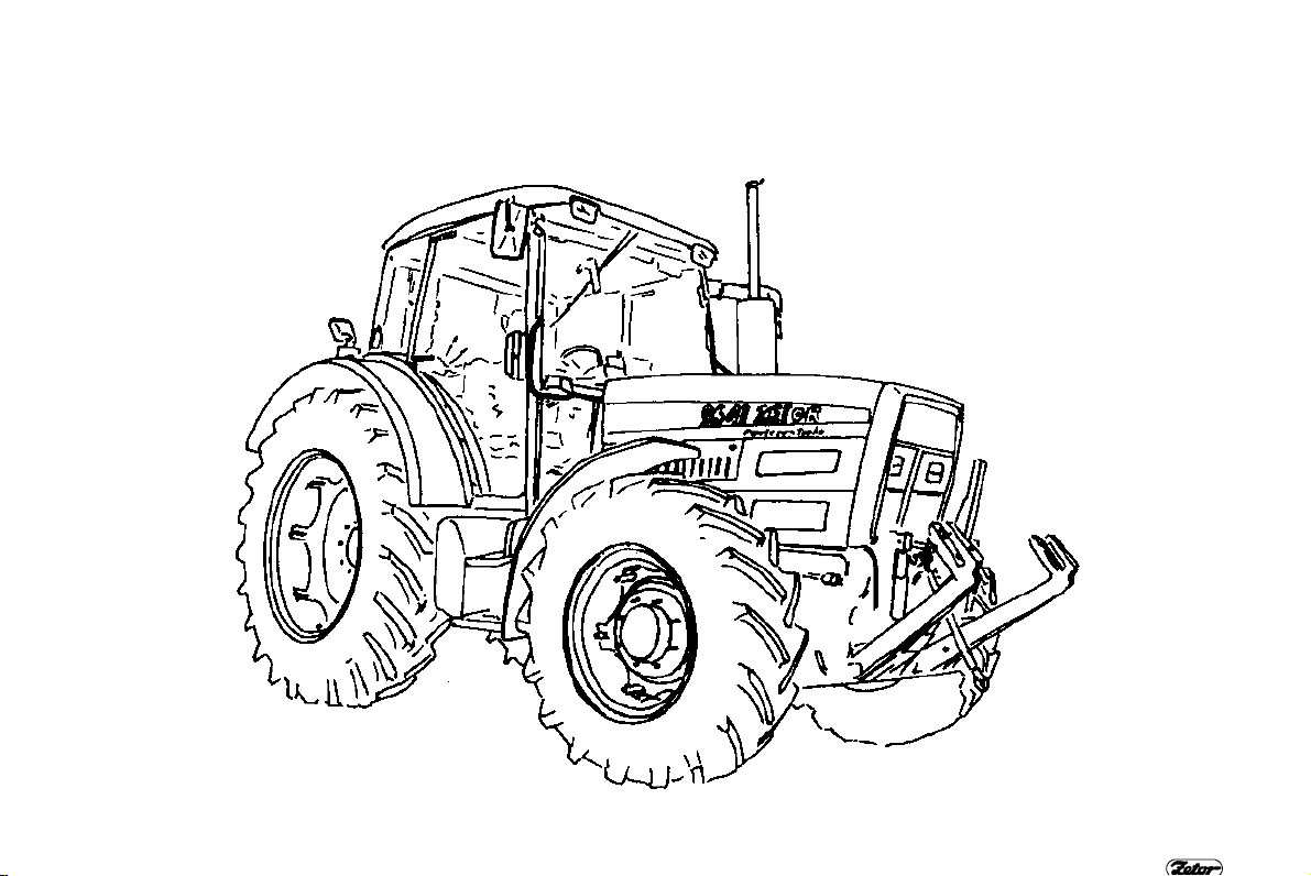
Zetor 8621 Forterra turbo - 60 kW
Zetor 9621
Forterra turbo - 67,5 kW
ZETOR 8621, 9621 FORTERRA TURBO
F 1
6
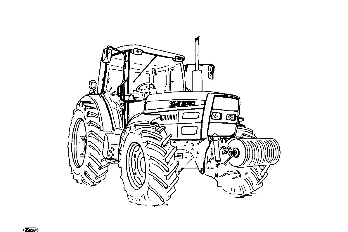
ZETOR 8641, 9641, 10641 FORTERRA TURBO
Zetor 8641 Forterra turbo - 60 kW
Zetor 9641
Zetor 10641 Forterra turbo - 76 kW
Forterra turbo - 67,5 kW
F 2
7
Zetor 11641 Forterra - 81 kW
ZETOR 11641 FORTERRA
F 3
8

LOCATION OF SERIAL NUMBERS Z 8621 - Z 10641 FORTERRA TURBO
F 4
9

LOCATION OF SERIAL NUMBERS Z 11641 FORTERRA
10
F 5
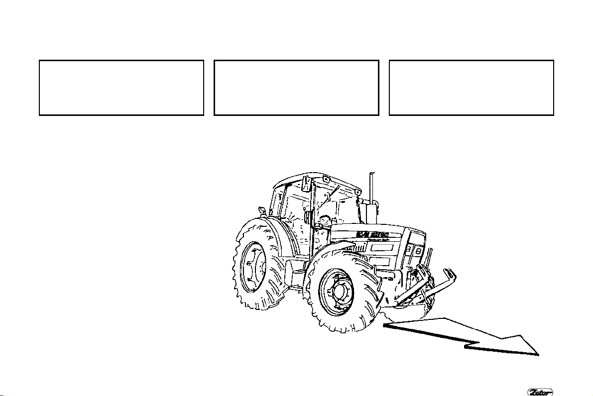
LOCATION OF SERIAL NUMBERS
Whenever you contact your authorized service dealer or the factory for order of service parts, always know the model and serial
numbers of your tractor. For your convenience, write those numbers in the frames below.
Tractor model
ZETOR 8621, 8641, 9621, 9641, 10641
ZETOR 11641
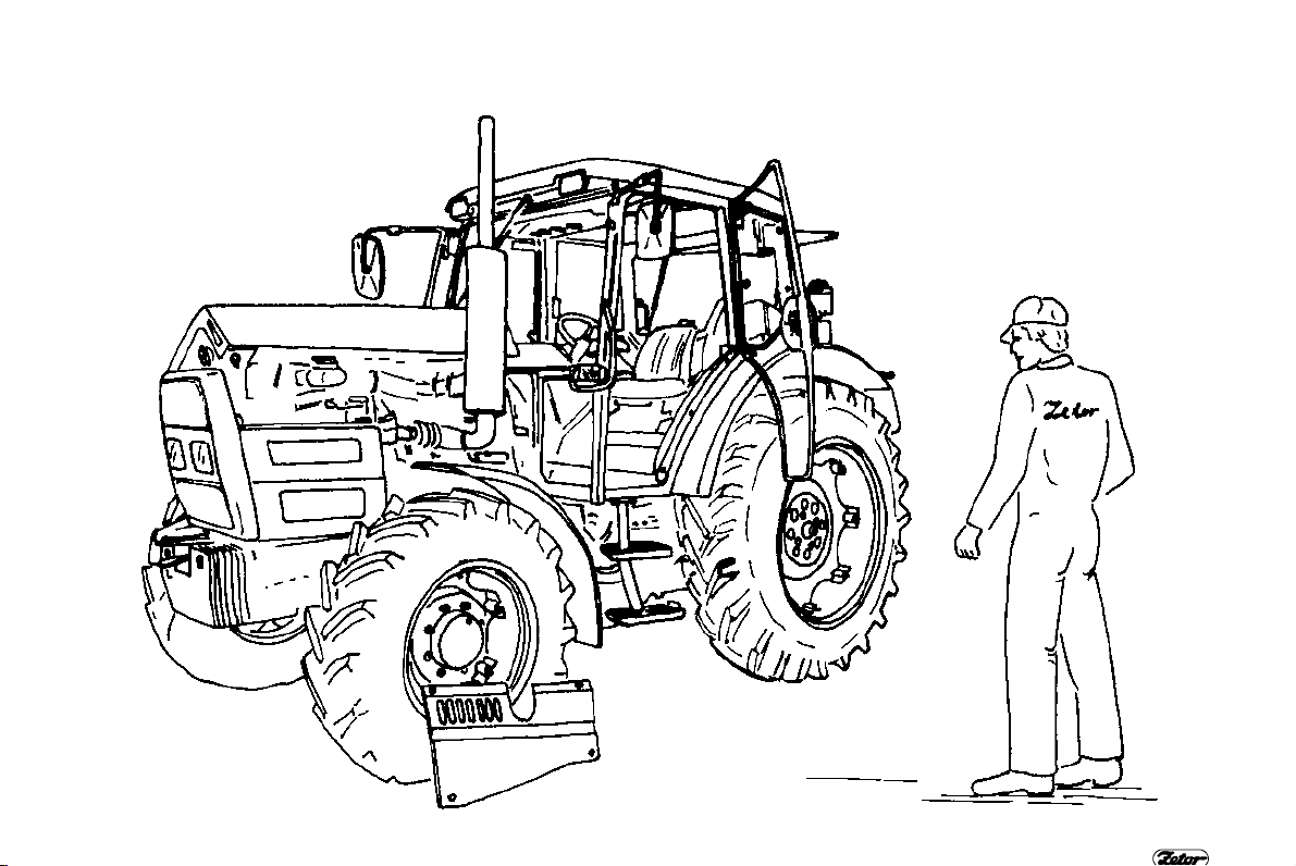
The “left“, “right“, “front“ and “back“ side
of the tractor is determined by traveling
direction.
Manufacturer reserves rights for
changes of design and option, that
improve the tractor features.
Tractor serial number Engine serial number
F 6
11

SAFETY INSTRUCTIONS FOR USERS
Keep extreme attention when
reading parts of operator’s manual
that are marked by these symbols.
You will find this symbol at all
important warnings identifying
the safety of tractor operation.
Keep these safety massages
and however regardless of the
hazard, be extremely careful!
Inform your cooperators and
other users about these messages.
This symbol marks all chapters
speaking about different operation, maintenance, adjustment
and safety rules at tractors
Z 11641Forterra.
Study carefully chapters marked
by this symbol before starting
with operating, servicing or
adjusting the tractor.
You will find this symbol whenever important informations on
operation, adjustment and repairs of starter motor.
Keep these regulations and be
extremely careful in these
cases!
This symbol marks such tractor
∗
equipment that is not assembled
as a standard (optionally
assembled equipment only).
GENERAL SAFETY REGULATIONS
1. Only a trained operator having a valid
driving license and being properly
acquainted with operating and safety
rules can operate the tractor.
2. Except of safety warnings mentioned
in this operator’s manual you must
respect all general safety and traffic
regulations of country where the tractor
works.
PROPER CLOTHING
3. Don’t wear loose clothing and free
flying long hair at operation.
4. Use suitable (prescribed) personal
protection means (working boots, gloves
etc.) at work.
STARTING ENGINE
5. Starting the engine when driving trac-
tor downhill is forbidden.
6. Starting tractor by means of towing
with another tractor or vehicle is allowed
only when the pull bar is used.
7. Tractor Z 11641 can not be
started without battery, with dis-
charged battery or without external source (see electronic governor of
injection pump).
12
7. Start the tractor from
driver’s seat only with
shifting lever in neutral
position. Life hazard when
starting by starter connec-
tor short circuit.
8. The key of the key switch must be in
position "I".
9. When preheating engine by electrical
heater, plug the heater first and connect
the cable into electricity after. After preheating disconnect the cable from
electricity first.
WARNING! Electrical shock hazard
OPERATION
11. Hoses of hydrostatic steering, brakes
and fuel system must be checked and
replaced in case of any damage indication. The damage indication is for
example: cracks on hose surface,
loosening of hose fittings (verify it by pulling of hose from fitting) and mechanical
damage of hose.
12. Brakes and steering must be permanently in perfect condition.
13. Brake pedals must be latched at
transportation with trailers and implements on the road.
14. Driving downhill without shifted gear
is forbidden!

SAFETY INSTRUCTIONS FOR USERS
15. Pay
special attention when driving on
hilly, muddy, sandy, icy and uneven terrain.
16. Don’t exceed the max. specified incli-
nation angle 120 for 4WD tractors (respectively 110 for 2WD tractors).
17. Don’t exceed the max. total weight of
trailers mentioned in the tractor serial
number plate or rear fender label.
18. Don’t use the differential lock when
driving into the turning.
19. Never get out or into the driving tractor. This is forbidden.
20. Reduce the travel speed to 20 km/h
when transporting agricultural implements hitched in the front three point
hitch.
21. The front axle load must not be lower
than 18 to 20 % of immediate total tractor weight when transporting agricultural
implements hitched in the rear three
point hitch.
TRANSPORTATION OF PERSONS,
OPERATION
22. Number of persons transported by
tractor must not exceed number mentioned in tractor technical license.
23. Persons, unauthorized to work with
attached implement, must not stand
between tractor and hitched implement
(machine).
24. Make sure neither any person nor
any obstacle allows driving before starting tractor move.
25. Max. allowed travel speed of tractor
and trailer equipped with one hose air
trailer brakes is 25 km/h.
26. Don’t exceed the max. specified
inclination angle 110 for tractors Z 8621
and Z 9621 and 120 for tractors Z 8641,
Z 9641, Z 10641, Z 11641.
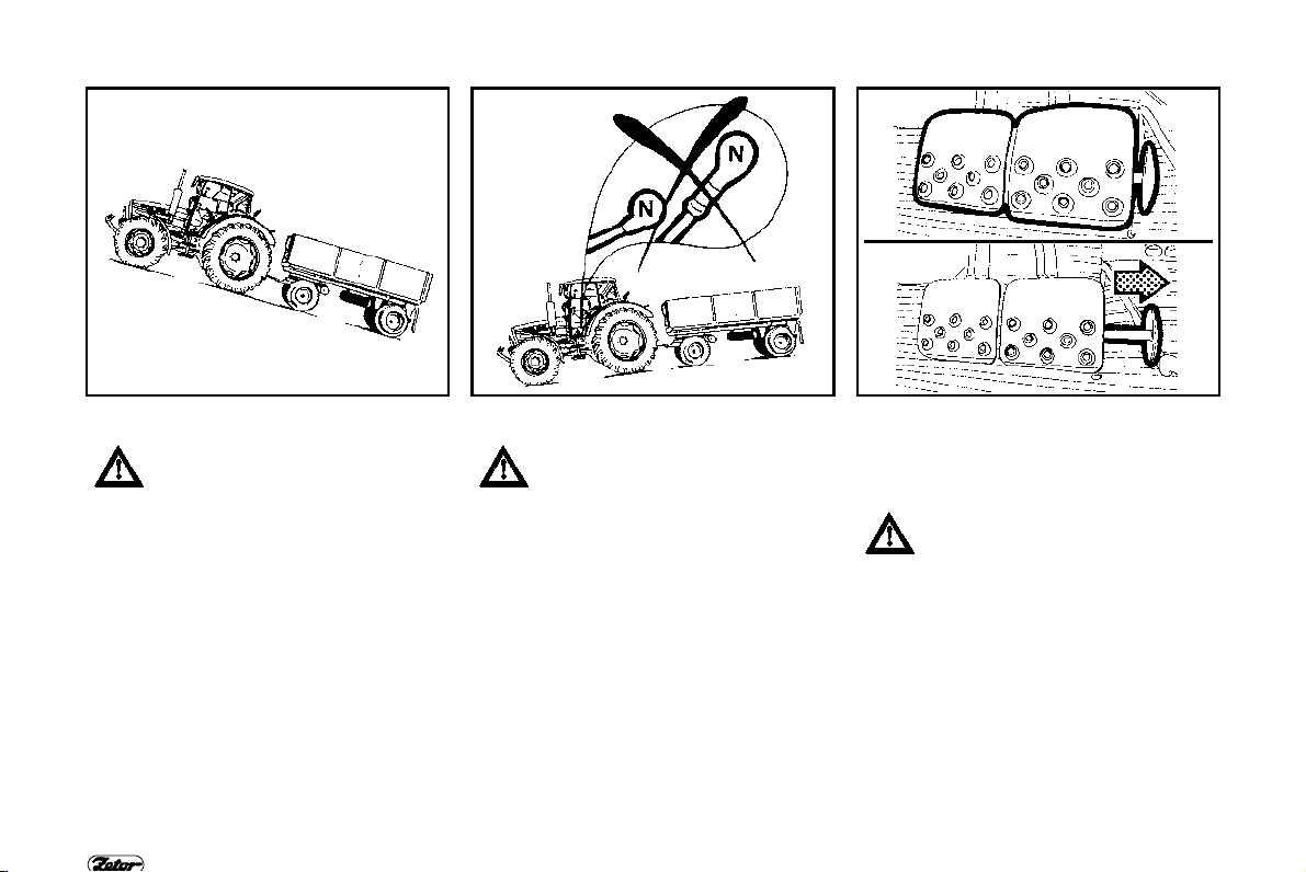
RELEASING AND PUSHING TRACTOR
27. Use a pull bar or a rope for releasing
an immobilized tractor. Never use
chains. It is life dangerous to stand near
the rope when releasing the tractor
28. Front hook assembled on front tractor
frame serves for pulling the alone tractor
only, i.e. without trailer or another implement.
29. Never use free wooden blocks,
planks or bars put between tractor and
pushed subject when pushing other vehicles (trailers, wagons etc.).
LEAVING TRACTOR
30. Do not park the tractor with attached
implement in lifted position.
31. Don’t forget to brake the tractor with
parking brake (shift the gear) remove the
key from key switch and lock the cab
before leaving tractor.
32. Shift the reverse lever into forward
position.
13
33. Brake the tractor with parking brake
before leaving tractor with running engine.
34. Usually use the left-hand side of tractor- left door when leaving tractor. Look
round if any vehicle coming, that could
jeopardize your safety when leaving and
open the door.
35. Use steps and handles when leaving
the tractor. When leaving tractor by the
right door pay attention being in space of
shifting levers and hand throttle control.
AT STOPPED ENGINE ONLY
36. All activities like refueling cleaning,
lubricating and adjusting tractor or
attached implement can be done at
stopped engine and stopped moving
tractor parts only, except of brake,
hydraulics and charging function inspection.
37. It is necessary to stop the engine
before removing bonnet side shields.
The engine can run in closed room and
house only when the perfect ventilation
works. Exhaust gases are health
dangerous.

SAFETY INSTRUCTIONS FOR USERS
FIRE PREVENTION RULES
38. Refuel
job and with stopped engine.
39. Don’t refuel the fuel tank up to the top
in summer season. Wipe the fuel
immediately when spilled.
40. Don’t refuel the tractor nearby an
open flame. Don’t smoke.
41. Don’t smoke and don’t use an open
flame when inspecting the battery
electrolyte level.
42. Keep properly the fire prevention regulations in areas with increased fire
hazard (hay-lofts, straw-stocks etc.).
43. If the tractor is equipped with a fire
extinguisher keep it ready for use.
44. Use the spark arrestor when working
in fire hazard environment.
HEALTH AND ENVIRONMENT PROTECTION
45. Tractors are not equipped with spe-
cial ventilation filters of inlet air coming
to the cab. That’s why tractors are not
intended for work with aerosols and
other substances harmful to health.
Kerosene, diesel fuel, mineral oils and
other products from crude oil used for
operation and maintenance of tractor
may cause an injury in case of direct
contact with skin and it can irritate
mocous membranes, eyes, digestive or
the tractor after finishing the
respiratory organs. Some of them might
cause the total poisoning when used.
46. Persons working with crude oil products must properly keep safety and
hygienic regulations, they must use the
suitable protectors and work in properly
ventilated areas.
WORKING WITH CRUDE OIL PRODUCTS
47. Wash properly your hands with mild
detergent and treat them with suitable
skin ointment or cream after finishing
work or before eating.
48. Remove oil drops from quick-couplers (from male and female) by textile
material after disconnecting or connecting hydraulic circuit.
PREVENTIVE DAILY SERVICE
49. Do this service every day or at least
every 10 hours.
SAFETY CAB
50. If corrosion or accident damages the
frame of safety cab it is necessary to
exchange the cab.
AIRCONDITIONING
51. In any case do not disassemble, turn
or manipulate with fittings of AC system.
This might create a sudden escape of
fluid and local freeze. This could create
a serious damage of tissue when
touching or when frozen in hands.
14
PREVENTIVE DAILY SERVICE
Do this service every day or at least every 10 hours
15
F 7

F 8 F 9 F 10
FUEL SYSTEM LEAKAGE
Inspect the fuel system for leakage including the fuel tank. Repair immediately
any leaks.
PREVENTIVE DAILY SERVICE
ENGINE OIL LEVEL
Check the engine oil and inspect the
lubrication system for leakage. Add the
oil to prescribed level.
COOLING SYSTEM
Inspect the engine cooling system for
leaks. Check the coolant level in the
expansion tank. Add the coolant to
"MAX“ level. The minimum allowed level
is on the lower mark.
16

F 11 F 12 F 13
FLUID SERVICE BRAKES
Inspect the brake and clutch circuit for
leaks and check the brake fluid level in
the brake fluid expansion reservoir.
PREVENTIVE DAILY SERVICE
AIR TRAILER BRAKES
Inspect the air brake system leak and
tractor break efficiency with trailer (see
„inspection of air brake leak“).
HYDRAULIC TRAILER BRAKES
Inspect the hydraulic brake system leak.
17

F 14 F 15 F 16
STEERING
Check oil level in the hydrostatic steering
oil tank. Retighten bolts and nuts of
steering tie-rods and arms.
PREVENTIVE DAILY SERVICE
TIRES AND WHEELS
Check the inflation air pressure of front
and rear tires. Inflate them up to the
recommended pressure according to
operating conditions. Check, eventually
retighten bolts of front and rear wheels.
Never drive tractor with loosened bolts of
wheels.
AIR CLEANER
The indicator indicates clogging of the
air cleaner, this indicator switches the
lamp on the dashboard in case of strong
clogging.
18

F 17 F 18 F 19
CAB FILTRATION
Check and eventually clean cab filters
located under the roof in front part. Filter
exchange interval depends upon dustiness of working condition. The partial
regeneration of filters can be done by
shaking-out or blowing by press air.
Filters are accessible after removing of
grills located in front of cab roof.
PREVENTIVE DAILY SERVICE
HITCHES
Check the status of hitches and attachments including the trailer.
AFTER OPERATION WITH FRONT
IMPLEMENTS
Remove the front mask to be able to
blow out impurities outside the tractor.
Clean the front part of radiators (radiators of transmission, AC condenser) by
the press air, blow it in direction from the
engine. Remove the rest of impurities
under the bonnet, otherwise their repeated suction into the cooling system
might appear.Inspect
hitch hydraulic circuit for leaks.
front three-point
19

F 20
SHORT FUNCTIONAL TEST
Check the lubrication indicator light is
“off“ after starting engine. Check the
function of charging (charging control
lamp must be off). Check the hydraulic
circuit of hydrostatic steering for leaks
and its function.
PREVENTIVE DAILY SERVICE
20

Tractor user must be properly
acquainted with recommended
operating and safety rules in
advance. It is too late to do it
within operation!
ACQUAINTANCE WITH TRACTOR
Safety cab ................................
Opening the door from outside.................................................................................. 23
Opening the door from inside .................................................................................... 23
Rear window................................................................ ................................ .............. 24
Side window .............................................................................................................. 24
∗Tiltable roof lid ......................................................................................................... 24
Opening for implementation purposes ......................................................................25
Windshield washer ................................ ................................ .................................... 25
Washer tank.............................................................................................................. 25
Washer control.......................................................................................................... 25
∗Passengerřs seat................................................................................................ ..... 26
Space for driverřs needs and toolbox................................ ................................ ........ 26
Rearview mirrors ................................................................ ................................ ....... 26
Seat adjustment for driverřs weight ................................ ........................................... 27
Longitudinal seat adjustment .................................................................................... 27
Vertical seat adjustment ................................ ................................ ............................ 27
Driverřs seat ∗ Grammer ................................................................ ........................... 28
Seat adjustment for driverřs weight ................................ ........................................... 28
Longitudinal seat adjustment .................................................................................... 28
Driverřs seat ∗ Cobo ................................ ................................ .................................. 29
Seat adjustment for driverřs weight ................................ ........................................... 29
Longitudinal seat adjustment and backrest adjustment ................................ ............ 29
Tiltable steering wheel .............................................................................................. 30
Angle adjustment ................................................................ ................................ ...... 30
Telescopic adjustment .............................................................................................. 30
Control panel of heating, ∗airconditioning and ∗ radio .............................................. 31
Four-speed switch of heating blowers ....................................................................... 31
Control panel on right cab pillar ................................ ................................................ 31
Ventilation outlets and radio speakers ...................................................................... 32
Defrosting the front windshield ................................................................ .................. 32
∗ Ac control ............................................................................................................... 33
Cooling the cab ......................................................................................................... 33
21
................................................................ ................. 23
Page

ACQUAINTANCE WITH TRACTOR
∗ Ac operation ................................
Location of dashboard .............................................................................................. 35
Description of instruments ........................................................................................ 35
Indicator lights........................................................................................................... 35
Location of dashboard .............................................................................................. 37
Description of instruments ........................................................................................ 37
Indicator lights and push buttons ................................................................ .............. 37
Switches with levers................................................................................................ .. 38
Light switch (a).......................................................................................................... 39
Front wheel drive switch (d) ...................................................................................... 39
Hazard light switch (f) ............................................................................................... 39
Switch of grill and cab headlight (g) .......................................................................... 40
Switch of rear (front) differential lock (j) .................................................................... 40
Turn signal, headlight and horn toggle switch (i) ...................................................... 40
Key switch................................................................................................................. 41
Key in "0" position ................................................................ ..................................... 41
Key in "I" position ...................................................................................................... 41
Key in “II“ position ................................................................................................ ..... 42
Throttle control lever ................................................................................................. 43
Stopping device ................................................................ ........................................ 43
Electronic hand throttle control ................................................................................. 43
Pedals and levers ................................................................ ..................................... 44
Main gear shifting lever and reversor lever ............................................................... 44
Shifting lever of road speed and reduced speed ...................................................... 44
PTO selection control lever for shifting of pto independent and ground speed ........ 45
Parking brake lever and ∗ pick up hitch control lever................................................ 45
Hydraulic control ................................................................................................ ....... 45
Hand control of selection control valve ..................................................................... 46
Fuel tank ................................................................ ................................ ................... 46
Draining plug of fuel tank .......................................................................................... 46
Average fuel consumption in litters per operating hour ............................................. 47
Battery switch................................ ............................................................................ 47
Location of information and safety decals ................................ ................................ 48
................................................................ ........... 33
22

SAFETY CAB
Use steps and handles when
getting out and in.
SAFETY CAB
F 21 F 22 F 23
OPENING THE DOOR FROM OUTSIDE
Cab doors can be locked from outside.
OPENING THE DOOR FROM INSIDE
1.
Lever for opening from inside.
2. Lever for locking from inside.
Door is kept in the opened position with
a gas strut.
Going with opened door is not recommended. Door might be damaged.
23

F 24 F 25 F 26
REAR WINDOW
Rear window is equipped with handle
and is kept in the open position by gas
struts.
We recommend latching the window in closed position when driving on uneven terrain - danger of
window cracking. Before starting
the job with machines implemented in the rear three point hitch
be sure that the interference
between hitched implement and
opened rear window is avoided
at the maximal lifting of the rear
three point hitch. In case of
interference we recommend to
work with closed window.
SAFETY CAB
SIDE WINDOW
A plastic latch in the opened position
locks side window.
∗TILTABLE ROOF LID
Pressing the mechanism opens roof lid.
Tiltable lid is kept with gas struts in the
opened position.
Tractor height is increased when
opened lid. That’s why close the
lid when passing through low
profiles.
24

F 27 F 28 F 29
OPENING FOR IMPLEMENTATION
PURPOSES
The bottom window is rigid and is
equipped with opening for connection of
controls with attached implements.
SAFETY CAB
WINDSHIELD WASHER
The washer nozzle is adjustable by
needle of max. diameter 0,8 mm.
WASHER TANK
Washer tank is accessible after tilting
the hood or after removing the front
mask.
WASHER CONTROL
The windshield washer sprays after
pressing the switch of front double
speed wiper. This switch is located on
the right cab pillar. Maximal time of uninterrupted spraying is 20 s.
25
F 30 F 31 F 32
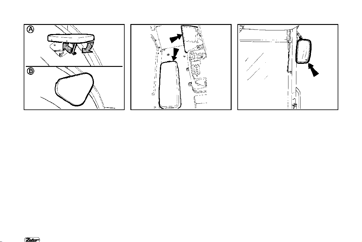
∗PASSENGER’S SEAT
Passengerřs seat is tiltable.
Unlock the seat strut and tilt the
A -
seat.
B - Seat is locked in its tilted position on
fender.
SAFETY CAB
SPACE FOR DRIVER’S NEEDS AND
TOOLBOX
The space is located on the left-hand
side nearby driverřs seat. Toolbox is
located behind the driverřs seat in the
rear part of cab.
REARVIEW MIRRORS
Adjust rearview mirrors before driving or
starting the job to be able to see the
road or the field.
26
F 33 F 34 F 35
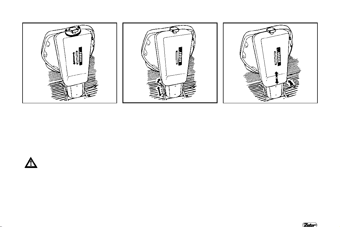
SEAT ADJUSTMENT FOR DRIVER’S
WEIGHT
The suspension of seat is adjustable for
driverřs weight from 50 up to 120 kg.
Turning of square knob does adjustment. Weight indicator is located in the
slot of rear seat cover. Spring stroke is
120 mm.
Do not adjust the seat on the go.
Danger of accident.
DRIVER’S SEAT MARS
LONGITUDINAL SEAT ADJUSTMENT
The seat can be longitudinally adjusted
within range „ 75 mm (11 positions).
VERTICAL SEAT ADJUSTMENT
The right hand side lever does vertical
seat adjustment within range „ 30 mm
( 3 positions).
27

F 36 F 37 F 38
DRIVER’S SEAT ∗ GRAMMER
Tractor can be equipped with the seat
Grammer as an option.
DRIVER’S SEAT - GRAMMER
SEAT ADJUSTMENT FOR DRIVER’S
WEIGHT
Adjust the seat by a plastic knob located
on the front part of seat support.
LONGITUDINAL SEAT ADJUSTMENT
Adjust the longitudinal position of seat by
a lever located on the left hand side of
the seat.
28

F 39 F 40 F 41
DRIVER’S SEAT ∗ COBO
Tractor can be equipped with the seat
Cobo as an option.
DRIVER’S SEAT - COBO
SEAT ADJUSTMENT FOR DRIVER’S
WEIGHT
Adjust the seat by rotating the lever after
its tilting into working position.
LONGITUDINAL SEAT ADJUSTMENT
AND BACKREST ADJUSTMENT
Adjust the seat by lever on the right
hand side of seat.
Adjust the backrest by rotating a plastic
knob located on the right, rear side of
seat.
29
F 42 F 43 F 44
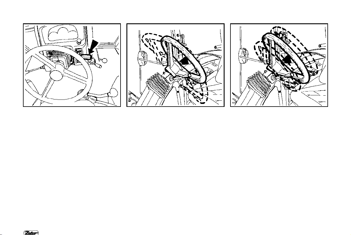
TILTABLE STEERING WHEEL
Tiltable steering column enables variable
angle and height adjustment of the
steering wheel. Both functions are operated by one lever.
CONTROLS
ANGLE ADJUSTMENT
Angle adjustment enables 10 positions
with step 4 in range: -16 up u to +24
down.
TELESCOPIC ADJUSTMENT
Steering wheel is adjustable within range
0 - 80 mm in any angle position.
30
F 45 F 46 F 47
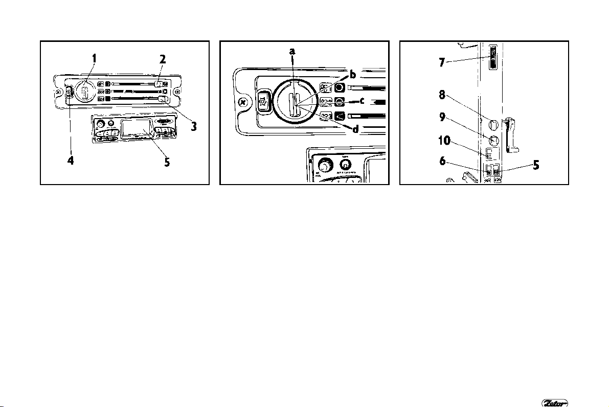
CONTROL PANEL OF HEATING, ∗AIRCONDITIONING AND ∗ RADIO
1.
Four-speed switch of heating blowers
2. Shut off heater and AC recycling
control
3. Heater valve control lever
- right - heating “on“
- left - heating “off“
4. ∗ switch of air-conditioning
5. ∗ Radio can be assembled into the
space under the heating panel
CONTROLS
FOUR-SPEED SWITCH OF HEATING
BLOWERS
a - vertical position - blower is “off“
b - first right position - blower low speed
c - second right position - blower middle
speed
d - third right position - blower high
speed
CONTROL PANEL ON RIGHT CAB
PILLAR
5. Control switch of rear PTO
6. ∗ Control switch of front PTO
7. Cab illumination
8. Two speed switch of front windshield
wiper and front washer.
9. Switch of rear window wiper.
10. ∗ Control switch of three point hitch
lifting (for lifting the implement when
turning in the field)
31

F 48 F 49
VENTILATION OUTLETS AND RADIO
SPEAKERS
Adjustable outlets of ventilation,
11.
heating and ∗AC
12. Radio speakers (only in case of
preparation assembly for ∗radio)
CONTROLS
DEFROSTING THE FRONT WINDSHIELD
For fast defrosting of front windshield the “A“ middle outlets needs to be directed to
the front windshield with 45 angle from vertical position the "B" side outlets directed
towards front corners of cab.
After front wind shield defrosting the side outlets can be directed towards door
glasses for their step by step defrosting. After defrosting the outlets should be
adjusted that way not to blow the air directly to the driver but to driver řs legs.
32

F 50 F 51 F 52
∗ AC CONTROL
The switch with symbol of flake controls
air-conditioning.
It is necessary to create overpressure in
the cab for the proper function of AC.
Thatřs why we recommend to shut all
windows, doors and cab roof cover.
CONTROLS
COOLING THE CAB
For fast cooling the inner space of cab
move the heating shut off lever (2) into
the left position (i.e. fresh air inlet is
closed). Choose the desired blower
speed by the four speed blower switch
(position 1, 2, 3). Set outlets with desired
angle to avoid direct blowing to persons
in the tractor cab (possible injury
because of intensive cooling of person řs
body).
AC OPERATION
With switched AC and permanently
closed heating shut off lever (2) in left
position (i.e. fresh air circuit closed) the
inner air is breathed out. Persons could
become tired. Thatřs why we recommend do move the lever (2) into the right
position (fresh air opened) immediately
after cooling down and reduction of the
inner temperature to desired level. The
fluent regulation of system is carried out
by partial opening of the heating valve
with heating control lever (3).
At the same time dry air from AC system
becomes moisture by this way.
33

DASHBOARD (
analogue)
34
F 53

LOCATION OF DASHBOARD
Analogue dashboard is assembled as a
standard equipment at tractors Z 8621, Z
8641, Z 9621, Z 9641, Z 10641.
DESCRIPTION OF INSTRUMENTS
A - indicator lights
B - air pressure gauge
C - tachometer with mechanical hour-
counter
D - fuel gauge
E - coolant thermometer
DASHBOARD (
INDICATOR LIGHTS
1. High beam light (blue). It lights if high
beam head lights are “ON .
2. Turn signal indicator light (green).
3. Turn signal indicator light (green) first trailer
4. Turn signal indicator light (green) second trailer
5. Indicator light of min. air pressure in
braking system (red): it lights if the
air pressure of air trailer brakes
drops under a critical margin i.e. 450
kPa.
6. Parking brake (red). It is “on“ if the
hand brake is set.
7. Charging indicator light (red). This is
“on“ after charging failure.
8. Lubrication indicator light (red). It is
“on“ if the engine oil pressure drops
below 120 to 60 kPa.
9. Air cleaner clogging indicator light is
“on“ after air cleaner clogging
(yellow).
10. Indicator light of hazard lamp
11. Indicator light of critical coolant
temperature (red) is “on“ after
exceeding temperature approx.
above 100 C (not connected).
12. Indicator light of Hi-Lo (torque
multiplier) (green 1st stage)
13. Indicator light of Hi-Lo (torque
multiplier) (green 2nd stage)
analogue)
14. Indicator light indicating critical failure in hydrostatic steering (not nocnnected)
15. Min. fuel level indicator light (orange). It lights if 1/6 to 1/10 of fuel tank
capacity stays at the fuel tank
16. PTO indicator light
17. Indicator light indicates wearing of
cardan brake.
18. Glowing indicator light (yellow)
19. Free
20. Free
35

DIGITAL DASHBOARD
36
F 54

LOCATION OF DASHBOARD
Digital dashboard is assembled as a
standard equipment on tractors Z 11641
and as an option on Z 8621 - Z 10641.
DESCRIPTION OF INSTRUMENTS
A -
indicator lights
B - air pressure gauge
C - tachometer with hour-counter
D - fuel gauge
E - coolant thermometer
F - display
DIGITAL DASHBOARD
INDICATOR LIGHTS AND PUSH
BUTTONS
Location of indicator lights on digital
dashboard is equal to analogue dashboard.
21. Indicator light of immediate travel
speed
22. Indicator light of PTO 1000 RPM
23. Indicator light of PTO 540 RPM
24. Symbol of immediate travel speed km/h
25. Symbol of RPM
26. symbol of voltage - V
27. Symbol of km
28. Symbol of battery
29. Symbol of traveled distance
30. Reset button for resetting the (day)
displayed data.
31. Button of battery voltage. Voltage is
displayed (with accuracy 0,1 V) and
simultaneously the indicator lights No
26 and 28 are “ON“.
32. Button of traveled distance (within
the day or from the time of last
resetting). No of kilometers is
displayed and simultaneously the
indicator lights No 27 and 29 are
“ON“.
33. Button of immediate travel speed in
v km.h-1, the speed is displayed and
simultaneously the indicator light No
21 and 24 is “ON“.
34. Button of PTO 1000 RPM. Speed
with accuracy 10 RPM is displayed
and simultaneously the indicator
lights No 22 and 25 are “ON“.
35. Button of PTO 540 RPM is displayed
and simultaneously the indicator
lights No 23 and 25 are “ON“.
37

CONTROLS
SWITCHES WITH LEVERS
Light switch
a b - Switch of front grill light and roof
light (low beam)
c - Fog light switch (ON - OFF). Functi-
on of fog light is indicated by illuminated symbol.
d - Working light switch (ON - OFF).
Function of working light is indica ted
by illuminated symbol.
e - Warning light switch
f - Front wheel drive control switch. En-
gaged front wheel drive axle is in-
dicated by switch symbol - ON .
g - plugged
h - plugged
i - plugged
j - differential lock (locks) button
k - stopping device - at tractors Z 8621
- 10641)
l - Toggle switch - turn signal, horn,
lights, high and low beam headlight
switch, acoustic horn.
38
F 55

F 56 F 57 F 58
LIGHT SWITCH (
a - Lights are “OFF“
b - Clearance lights and tail lights ,
license plate light and illumination of
instruments are “ON“
c - All electrical appliances are nocn-
nected as in “b“ position. Moreover
low and high beam lamps are ON
according to the position of toggle
switch.
a)
CONTROLS
FRONT WHEEL DRIVE SWITCH (d)
Use the front driving axle for
increasing the pulling force when
rear wheels slippage.
a - front driving axle disengaged
b - front driving axle engaged
Front driving axle is engaged at stopped
tractor (braked tractor, stopped engine).
Front driving axle is engaged in the
basic position (indicator lamp “ON ) and
the switch disengages the axle.
HAZARD LIGHT SWITCH (f)
a - Hazard lights are “off“.
b - Hazard lights are “on
Flashing of indicator light on the
dashboard indicates function of hazard
lights.
39

F 59 F 60 F 61
SWITCH OF GRILL AND CAB HEADLIGHT (
a - cab roof headlights are “OFF
b - cab roof headlights are “ON
The switch controls the headlights in the
mask grill or in the tractor cab roof.
Use the cab roof headlights only if the
front grill headlights are covered by
attached implement hitched in the front
three point hitch. Symbol on the switch
indicates that cab roof headlights are
“ON . High beam can light in the grill
mask only.
g)
CONTROLS
SWITCH OF REAR (FRONT) DIFFERENTIAL LOCK (j)
a - differential lock disengaged
b - differential lock engaged
Diff lock is engaged by pressing the diff
lock push button that is returned into the
previous position after loosing.
Symbol on the switch indicates that the
diff lock is engaged.
Differential lock is automatically
disengaged after pressing brake pedals.
At tractors equipped with front driving
axle with pin lock, this is engaged
simultaneously with the rear diff lock.
TURN SIGNAL, HEADLIGHT AND
HORN TOGGLE SWITCH (i)
a - Turn signal - right.
b - Turn signal - left.
c - Acoustic horn press the toggle
switch in axis direction
d - High beam light
40

F 62 F 63 F 64
KEY SWITCH
Key switch is located on the front part of
steering wheel support under the
dashboard.
KEY SWITCH
KEY IN "0" POSITION
All electrical appliances controlled by the
key switch are disconnected. The key
can be removed.
KEY IN "I" POSITION
All electrical appliances controlled by the
key switch are connected except of
starter motor. The key is located in this
position when running the engine.
41

F 65
KEY IN “II“ POSITION
Starter motor is connected in this position. All electrical appliances controlled
by the key switch are connected except
of wipers, washer, blower of cab and AC.
The key is turned automatically to “I“
position after starting.
KEY SWITCH
42
THROTTLE CONTROL LEVER
A -
Max. throttle
B - Stop
Only at tractors Z 8621 - Z 10641.
CONTROLS
F 67 F 68 F 69
STOPPING DEVICE
Pull the stopping device upwards and
keep it in pulled position, the engine will
be immediately stopped.
Only at tractors Z 8621 - Z 10641.
ELECTRONIC HAND THROTTLE
CONTROL
The system electronically controls speed of engine and controls
fuel delivery (see chapter
Electronic governor). Engine is stopped
by turning the key into “0“ position at this
system.
43

F 70 F 71 F 72
PEDALS AND LEVERS
Travel clutch pedal
1.
2. Foot operated service brake pedals
connected by latch
3. Foot throttle pedal
CONTROLS
MAIN GEAR SHIFTING LEVER AND
REVERSOR LEVER
1. Main shifting lever with push buttons
for three-stage Hi-Lo (torque multiplier)
2. Reversor lever
SHIFTING LEVER OF ROAD SPEED
AND REDUCED SPEED
The lever is located on the right hand
side at driverřs seat.
H - road speeds
N - neutral
L - reduced speeds
44

F 73 F 74 F 75
PTO SELECTION CONTROL LEVER
FOR SHIFTING OF PTO INDEPENDENT AND GROUND SPEED
Lever is located on the right hand side at
driverřs seat.
PTO -
N - Neutral position
PTO
synchro - PTO ground speed is
Independent PTO speed is
shifted
shifted (RPM depends upon
tractor travel speed)
CONTROLS
PARKING BRAKE LEVER AND ∗ PICK
UP HITCH CONTROL LEVER
1. Parking brake lever
a - disbraked
b - braked
2. Pick up hitch control lever
a - transport position
b - pick up hitch is unlocked (lowered)
HYDRAULIC CONTROL
a - mechanical hydraulic control
b - Electro-hydraulic
Description of hydraulic control is mentioned in chapter hydraulic equipment.
45

F 76 F 77 F 78
HAND CONTROL OF SELECTION
CONTROL VALVE
At tractors equipped with ∗hydraulic
control of pick up hitch, lowering the pick
up hitch is controlled by SCV control
lever (a) (usually the right hand side
SCV lever or by operatorřs choice).
ACQUAINTANCE WITH TRACTOR
FUEL TANK
Plastic fuel tank with capacity 180 liters
is assembled as a standard.
Do not step on the fuel tank!
DRAINING PLUG OF FUEL TANK
The opening for draining impurities and
fuel is located in the bottom part of fuel
tank.
46

F 79 F 80
AVERAGE FUEL CONSUMPTION IN
LITTERS PER OPERATING HOUR
Tractor type
Z 8621, 8641 17,99 14,39 10,07
Z 9621, 9641 20,07 16,06 11,24
Z 10641 21,86 17,49 12,24
Z 11641 28,30 22,64 15,84
Engine load
100% 80% 50%
ACQUAINTANCE WITH TRACTOR
BATTERY SWITCH
Battery switch is located on the left hand
side underneath the front part of cab.
47

ACQUAINTANCE WITH TRACTOR
LOCATION OF INFORMATION AND
SAFETY DECALS
2. Warning decal - hand
3. Decal 4-speed transmission
5. warning of operating space
48
6. coefficient of absorption 0,86
F 81

7. warning of starter motor
8. ECE label
9. EPA label
ACQUAINTANCE WITH TRACTOR
49

NOTE
50

ELECTRONIC ENGINE GOVERNOR
Schema of electronic engine control system
Push button - MAX ................................................................................................ .... 53
Push button - MIN ..................................................................................................... 53
Push button - MEM....................................................................................................53
Indicator lamp H/O ....................................................................................................54
Function of electronic governor ................................................................................. 54
Setting the temporary memory .................................................................................. 54
Resetting and deleting the temporary memory ......................................................... 55
Setting the permanent memory ................................................................................. 55
Permanent memory recall - H/O lamp is off .............................................................. 56
Permanent memory recall - H/O lamp is on .............................................................. 57
Memory reset - return to pedal control ...................................................................... 57
1. Setting the entry and exit speed at tillage and enter to memory ........................... 58
2. Setting the operating speed and enter to temporary memory ............................... 58
3. Tillage with operating speed temporarily memorised ............................................ 58
4. Reset of temporary memory and recall of entry and exit speed memory .............. 59
5. Reset of permanent memory, setting the operating speed and its temporary
memorising................................................................................................................ 59
6. Tillage with operating speed temporarily memorised ............................................ 59
1. Setting the PTO speed ................................ ................................ .......................... 60
2. Setting the constant travel speed .......................................................................... 60
3. PTO speed engagement and setting the PTO speed for 540 or 1000 RPM ......... 60
4. Temporary memorising the PTO speed ................................................................ 61
5. Manoeuvring with tractor and reset of temporary memory .................................... 61
............................................................. 52
Page
All tractors Z 11641 are equipped
with electronic engine governor.
51

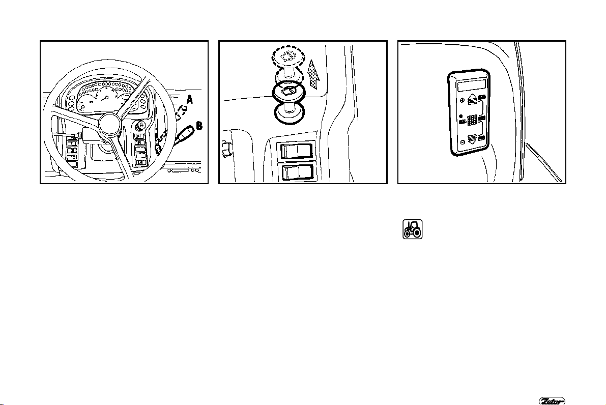
ELECTRONIC ENGINE GOVERNOR
SCHEMA OF ELECTRONIC ENGINE
CONTROL SYSTEM
System consists of the following main
components and of wiring harness.
Electronic control unit ( E.C.U.)
A B - Hand throttle control ’ the control
has three keypads and LED.
C - Potentiometer ’ mechanically linked
with foot throttle pedal
D - Engine speed sensor
E - Governor ’ control actuator
52
RPM
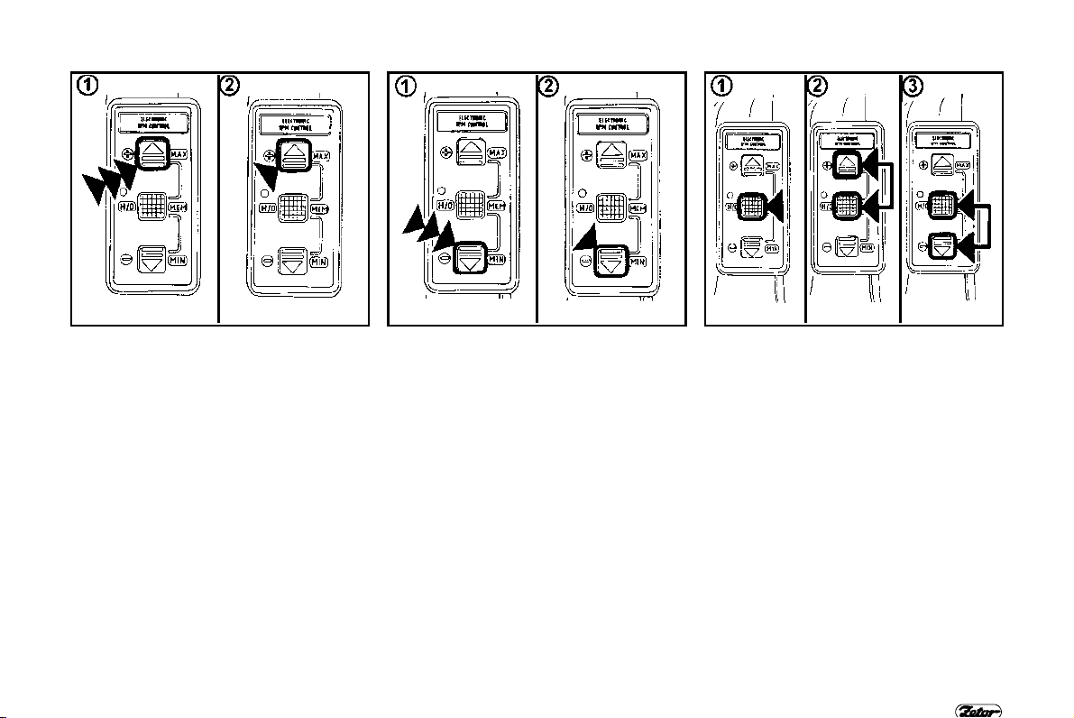
ELECTRONIC ENGINE GOVERNOR
RPM1 RPM2 RPM3
PUSH BUTTON - MAX
Push button (keypad) - max serves for
increasing the engine speed. Engine
speed can be increased by keypad max. by two ways.
1.
Pulse pressing the keypad causes
gradual change of engine speed.
2. Permanent pressing the keypad
causes the immediate increase of
engine speed. Engine speed is increased up to time when you release
the keypad.
This keypad controls the memory if
combined with keypad MEM.
PUSH BUTTON - MIN
Push button (keypad) - MIN serves for
decreasing the engine speed. Control of
keypad MIN is equal to control of keypad
MAX for increasing the engine speed (1,
2).
This keypad controls the memory if
combined with keypad MEM.
PUSH BUTTON - MEM
Push button (keypad) - MEM serves for
entering, recalling and resetting the
engine speed in memory of system. This
keypad is used either separately (1) or in
connection with keypads MIN or MAX
(2, 3).
53

RPM4 RPM5 RPM6
INDICATOR LAMP
Indicator lamp H/O indicates switching
on or off the function of keypad MEM.
Indicator lamp indicates entering, recalling and resetting the engine speed in
memory of system and moreover it indicates limiting the range of engine
speed increase or decrease.
H/O
ELECTRONIC ENGINE GOVERNOR
FUNCTION OF ELECTRONIC GOVERNOR
1. Setting the temporary memory
2. Resetting and deleting the temporary
memory
3. Setting the permanent memory
4. Permanent memory recall - H/O lamp
is off
5. Permanent memory recall - H/O lamp
is on
6. Memory reset - return to pedal control
Engine speed, determined for memorizing to memory system, can be set
either by throttle control or by foot
throttle control (throttle pedal). Enter,
recall and reset of memory is possible
on the keyboard of hand throttle control.
SETTING THE TEMPORARY MEMORY
1. Indicator lamp H/O must be off.
2. Set the desired engine speed by
hand (keypad MIN or MAX) or foot
throttle control, for example 1600
RPM.
3. Press the keypad MEM; indicator
lamp H/O turns on.
4. Set engine speed 1600 RPM is
memorized.
Since this setting, it is not necessary to
set the engine speed anymore. You can
loose the foot throttle pedal. Engine
speed is maintained in the constant level
(for example 1600 RPM) temporarily
memorized, independently upon tractor
load.
54

RPM7 RPM8 RPM9
With such way set constant value (for
example 1600 RPM) it is possible to set
the engine speed by means of hand or
foot throttle control and the entered
memory will not be lost.
a -
You can increase or decrease the
engine speed by hand throttle control. Increase or decrease the engine
speed by interrupted pressing of
keypad MIN or MAX.
b - You can only increase the engine
speed by foot throttle control. After
loosing the foot throttle pedal the
engine speed drops again to the
value entered in temporary memory
(for example 1600 RPM).
ELECTRONIC ENGINE GOVERNOR
RESETTING AND DELETING THE
TEMPORARY MEMORY
1. Indicator lamp H/O is on.
2. Press the keypad MEM.
3. Indicator lamp H/O turns off. Temporary memory is off. It is not possible
to recall it again. In this time the set
value (for example 1600 RPM) is definitively deleted. The same will happen after switching off the key in the
key switch.
SETTING THE PERMANENT MEMORY
1. Indicator lamp H/O must be off.
2. Set the desired engine speed by
hand (keypads MIN or MAX) or foot
throttle control.
3. Press both keypads MEM and MIN
or MAX depending if you want to
enter into memory minimal or
maximal engine speed.
4. Indicator lamp H/O is on. Since this
setting the engine speed is entered
into the permanent memory.
55

RPM10 RPM11 RPM12
In case the minimal engine speed is
1.
being entered it is not possible to
enter the value higher than 1500
RPM. If you will try it the system will
automatically enter 1500 RPM.
2. In case the maximal engine speed is
being entered it is not possible to
enter the value smaller than 1500
RPM. If you will try it the system will
automatically enter 1500 RPM.
ELECTRONIC ENGINE GOVERNOR
Two values can be entered into
permanent memory i.e. chosen minimal
and maximal engine speed. These
values will be memorized in the
permanent memory even after stopping
the engine and removing the key from
the key switch.
If you will enter the new minimal and
maximal engine speed into the
permanent memory the previously
entered values will be deleted and
replaced by new ones i.e. new values
set by you.
PERMANENT MEMORY RECALL - H/O
LAMP IS OFF
1. Indicator lamp H/O is off.
2. Press the keypad MIN or MAX
(depending if you want to recall
maximal or minimal speed entered in
memory) and keep it pressed (longer
time than 0,5 sec.).
3. Indicator lamp H/O turns on. Memory
is recalled. Engine will maintain the
recalled constant speed.
Engine speed can be set after this action
by:
56

RPM13 RPM14 RPM15
a -
by hand throttle control i.e. by
interrupted pressing the keypads
MIN or MAX. After loosening the
keypads, the engine speed will be
changed to engine speed recalled
from the permanent memory.
b - by foot throttle control (by throttle
pedal) and the engine speed can be
increased only. After loosening the
keypads, the engine speed will be
changed to engine speed recalled
from the permanent memory.
ELECTRONIC ENGINE GOVERNOR
PERMANENT MEMORY RECALL - H/O
LAMP IS ON
1. Indicator lamp H/O is on. Indicator
lamp is on in that case if you have
already recalled minimal or maximal
speed from the permanent memory.
Or if the set speed is entered in the
temporary memory.
2. Press the keypad MIN or MAX depending on which speed you want to
switch the memory of system and
keep it pressed (longer time than 0,5
sec.).
Attention! In case the indicator lamp
H/O indicated the function of temporary
memory (set speed was entered in the
temporary memory) this engine speed
will be definitively deleted after recall of
values from permanent memory.
57
MEMORY RESET - RETURN TO PEDAL CONTROL
1. Indicator lamp H/O is on. Tractor
works with engine speed entered in
temporary or permanent memory.
2. Press the keypad MEM.
3. Indicator lamp H/O turns off. Temporary or permanent memory is
switched off. Set engine speed in
temporary memory is deleted, set
engine speeds in permanent memory
are kept.
Now engine speed can be set by foot
throttle pedal or hand throttle control
without any restriction (by interrupted
pressing of keypad MIN or MAX).

. SETTING THE ENTRY AND EXIT
1
SPEED AT TILLAGE AND ENTER TO
MEMORY
1. Indicator lamp H/O is off.
2. Set the entry and exit travel speed of
tractor by the keypad MIN or MAX
(for example 1600 RPM)
3. Press both keypads MAX and MEM.
(the speed is entered into permanent
memory).
4. Indicator lamp H/O is on.
ELECTRONIC ENGINE GOVERNOR
2. SETTING THE OPERATING SPEED
AND ENTER TO TEMPORARY MEMORY
1. Turn off the indicator lamp H/O by
keypad MEM.
2. Set the operating engine speed by
foot throttle control (foot throttle
pedal)
3. Press the keypad MEM. Indicator
lamp H/O turns on. The speed is
entered in permanent memory.
RPM16
3. TILLAGE WITH OPERATING SPEED
TEMPORARILY MEMORISED
Since you entered the operating engine
speed into the temporary memory no
correction of speed is necessary.
System automatically maintains the
constant level of operating engine speed
entered in the temporary memory
independently upon tractor load.
58
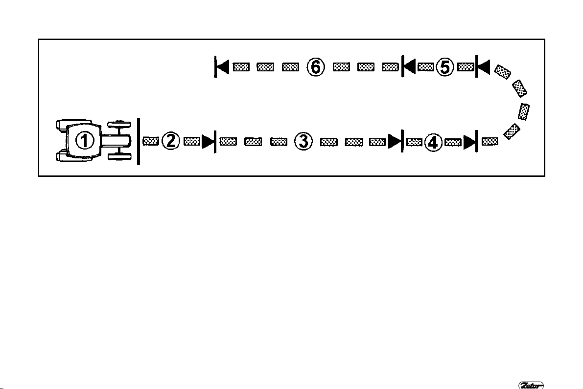
4. RESET OF TEMPORARY MEMORY
AND RECALL OF ENTRY AND EXIT
SPEED MEMORY
1.
Increase engine speed by foot
throttle control to avoid sudden dropping of speed.
2. Press the keypad MEM. Indicator
lamp H/O turns off. Temporary memory is switched off and entered
value is definitively lost.
3. Press and keep (longer than 0,5
sec.) the keypad MAX. You will recall
the value entered in permanent memory by this way. Now the engine
works in regime of entry and exit
speed.
ELECTRONIC ENGINE GOVERNOR
5. RESET OF PERMANENT MEMORY,
SETTING THE OPERATING SPEED
AND ITS TEMPORARY MEMORISING
1. Press the keypad MEM. Indicator
lamp H/O turns off. Permanent memory is switched off.
2. Again set the operating engine speed
by foot throttle control (foot throttle
pedal).
3. Press the keypad MEM. Indicator
lamp H/O turns on. The speed is now
entered into temporary memory.
RPM16
6. TILLAGE WITH OPERATING SPEED
TEMPORARILY MEMORISED
Activities that are mentioned in point 6
are equal to point 3.
59

. SETTING THE PTO SPEED
1
Choose the PTO speed 540 or 1000
RPM by the end of rear PTO shaft.
ELECTRONIC ENGINE GOVERNOR
2. SETTING THE CONSTANT TRAVEL
SPEED
1. Set the engine speed by keypad MIN
or MAX corresponding to desired
travel speed.
2. Indicator lamp H/O stays off.
RPM17
3. PTO SPEED ENGAGEMENT AND
SETTING THE PTO SPEED FOR 540
OR 1000 RPM
1. Engage the independent speed of
PTO shaft.
2. Set the engine speed by foot throttle
control (foot throttle pedal) corresponding to desired speed of PTO
shaft in range 540 or 1000 RPM.
60

4. TEMPORARY MEMORISING THE
PTO SPEED
1.
Press the keypad MAX. Indicator
lamp H/O turns on.
Since this the set engine speed corresponding the PTO speed 540 or 1000
RPM is entered in the temporary memory. System will automatically maintain
the constant speed of PTO independently upon load of tractor.
ELECTRONIC ENGINE GOVERNOR
RPM17
5. MANOEUVRING WITH TRACTOR
AND RESET OF TEMPORARY
MEMORY
1. Disengage the PTO shaft when
manoeuvring the tractor with implement.
2. Press the keypad MEM. Indicator
lamp H/O turns off.
Since this the temporary memory is
switched off and values entered in temporary memory are definitively lost. The
engine works with speed corresponding
to travel speed set by keypads MIN or
MAX.
61

NOTE
62

Be familiar with shifting
pattern and test all positions of shifting lever at
stopped engine before driving the new tractor.
Be sure that the technical
status of tractor corresponds to the safety traffic
condition before driving.
OPERATION
Page
Before starting
Starting the engine equipped with glow plugs ........................................................... 65
Starting the engine equipped with electronic thermostart ......................................... 66
If engine doesnřt start................................................................................................ 67
Forbidden starts ........................................................................................................ 67
∗ Coolant heater........................................................................................................ 68
Starting the engine with coolant heater ..................................................................... 68
Immediately after starting ................................ ................................ .......................... 69
Preheating the engine ................................................................ ............................... 69
Gear shifting.............................................................................................................. 70
Reversor lever........................................................................................................... 70
Shifting the road and reduced speeds ................................ ................................ ...... 70
Shifting from lower to higher gear speed ..................................................................71
Shifting from higher to lower gear ............................................................................. 71
Three stage hi-lo (torque multiplier) .......................................................................... 71
Indication of hi-lo function ......................................................................................... 72
Hi-lo shiftinng ................................................................ ............................................ 72
Acceleratig the tractor ............................................................................................... 73
Driving uphill.............................................................................................................. 74
Driving downhill ................................................................ ......................................... 74
Service brakes ................................................................ .......................................... 74
Front drum brakes ..................................................................................................... 75
∗ Front cardan brake ................................................................ ................................. 75
Air trailer brakes ........................................................................................................ 75
Warning device of air pressure drop ......................................................................... 76
∗Single and double hose air brakes .......................................................................... 76
Air tanks ................................................................................................ .................... 76
Single hose air trailer brakes..................................................................................... 77
Double hose air trailer brakes ................................................................ ................... 77
Hydraulic trailer brakes ............................................................................................. 78
Control of front driving axle ................................................................ ....................... 79
Driving with engaged front driving axle ................................ ..................................... 79
................................................................ ........................................... 65
63

OPERATION
Page
Free space round cardan shaft
Stopping the tractor - parking brake.......................................................................... 80
Stopping the engine .................................................................................................. 80
Leaving the tractor .................................................................................................... 80
................................................................ ................. 79
64
BEFORE STARTING
Before starting the engine be
sure that
1.
the tractor is braked by
parking brake.
2. main shifting lever and reversor lever is in neutral position.
If the shifting lever is in a different then neutral position tractor can not be started - safety interlock switch is not actuated.
OPERATION
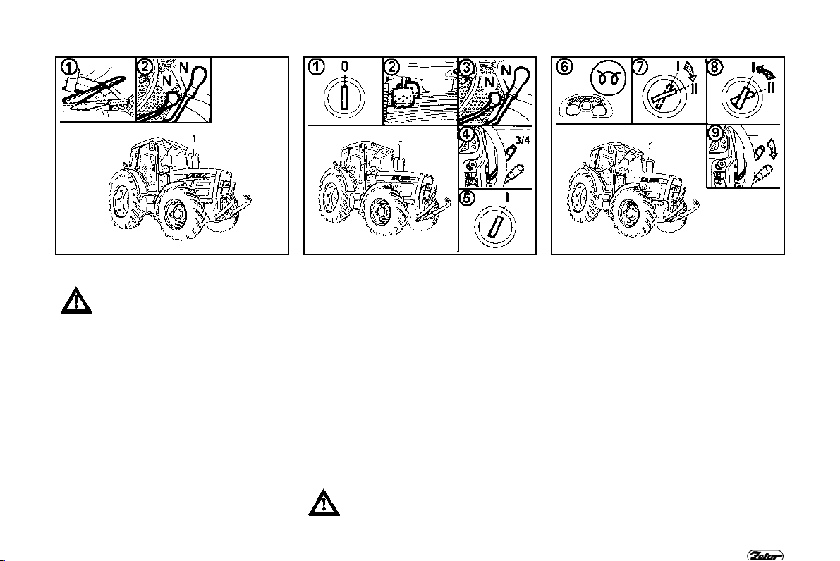
F 82 F 83 F 84
STARTING THE ENGINE EQUIPPED
WITH GLOW PLUGS
Tractors Z 8621 - 10641 are equipped
with glow plugs as a standard.
1. Insert the key into the key switch
("0" position).
2. Depress the clutch pedal.
3. Move the main shifting lever and
reversor lever into neutral.
4. Set the increased throttle control
(approx. 3/4 maximal delivery).
5. Turn the key into "I" position. Yellow
indication lamp on the dashboard is
“ON“. The indication lamp indicates
correct function of glowing.
In case the indication lamp is
flashing the glowing system
failed. In spite of this, the engine
can be started but without function of
65
glow plugs. Let repair the indicated
failure in a specialized workshop.
6. Wait until the indication lamp is off.
7. Turn the key into "II" position (start).
8. Release the key immediately after
starting the engine. Do not start longer then 15 sec.
9. After starting the engine, reduce
gradually the fuel delivery. Avoid
running the engine at high speed.
Note: According to the personal
experiences of driver it is possible to
start sooner then glow indicating lamp is
off. Proceed similarly when starting the
hot engine.

F 85 F 86 F 87
STARTING THE ENGINE EQUIPPED
WITH ELECTRONIC THERMOSTART
Tractors Z 11641 are equipped
with electronic
standard.
Thermostart enables starting the engine
at lower temperatures. Time of glowing
and the process of fuel ignition in suction
manifold is controlled automatically.
Note: Before proper starting we recommend to prime the fuel system by several strokes of fuel delivery pump.
thermostart as a
OPERATION
1. Insert the key into the key switch
("0" position).
2. Depress the clutch pedal.
3. Move the main shifting lever and
reversor lever into neutral.
4. Turn the key through "I" position into
"II" position and (start) crank the
engine only (when “hot starts„ this
point can be eliminated).
5. Turn the key into "I" position. Yellow
indication lamp on the dashboard is
“ON“. The indicator lamp indicates
correct function of thermostart
glowing (when higher ambient temperatures the thermostart function is
not initiated).
6. Wait until the indication lamp is off.
7. Turn the key into "II" position (start).
8. Release the key immediately after
starting the engine. Do not start
longer time then 10 sec.
9. After starting the engine, avoid running the engine at high speed.
66

F 88 F 89
IF ENGINE DOESN’T START
Wait 30 seconds. Turn the key into position "0" and repeat starting.
Never help to the stopping
engine by starter motor. You will
avoid damage of starter motor.
Never start longer than 10 sec. at
tractors Z 11641. Start needs to
be repeated.
OPERATION
FORBIDDEN STARTS
It is forbidden to start the
tractor by short circuit of
starter motor connectors.
Start from the driver’s seat
only.
Disconnect the ground battery
pole, shift all levers into neutral
position, including PTO engagement, when any manipulation
with starter or repairing it. A
cover protects starter motor connectors.
67

F 90 F 91
∗ COOLANT HEATER
Coolant heater is assembled into engine
block as an option. At tractors Z 8621 Z 10641output of heater is 1000 W with
voltage 220 V of alternating electrical
current.
At tractors Z 11641 output of
heater is 500 W with voltage 220
V of alternating electrical current
OPERATION
STARTING THE ENGINE WITH COOLANT HEATER
Heater enables starting the engine at low ambient temperature by preheating the
coolant. The electrical installation and its protection against electrical shock hazard
must be done according to the proper regulations
Plug the heater first.
1.
2. Plug the cable with heater into 220 V electricity after.
With regard to reduction of engine wear when starting at low temperatures, producer
recommends to use heater. The time of preheating depends upon the ambient
temperature (1 to 2 hours are sufficient before supposed starting).
After heating, unplug the electricity first and the heater after.
ELECTRICAL SHOCK HAZARD!
68

F 92 F 93
IMMEDIATELY AFTER STARTING
After starting set the engine
speed to 800 up to 1000 RPM
and let the engine idle for 3
minutes without load.
In this time check for proper lubrication,
charging (indicator lights must be “off“)
and other functions assuring the correct
engine operation. Time of engine idle
without load must be kept especially in
winter season.
OPERATION
PREHEATING THE ENGINE
Continue with farther preheating the engine already while driving. Warming
up the engine by long idle run or fast increase of speed is dangerous for the
engine.
Do not exceed engine speed above 2 000 RPM until the coolant temperature
reaches 45°C.
69

F 94 F 95 F 96
GEAR SHIFTING
Tractors are equipped with four speed
synchronized gearbox, three stage
power shift - Hireversor, and two stage reduction gear.
Four-speed gearbox is shifted by the
main shifting lever with grip push buttons
intended for Hi-Lo control (1). Forward
and reverse speed is shifted by reversor
lever (2).
The fourth speed can not be
shifted when shifted reverse
speed (it is blocked).
Lo (torque multiplier)
OPERATION
REVERSOR LEVER
You select the tractor direction by
reversor shifting lever (forward, reverse).
Forward speed (24 speeds)
F -
Neutral
A -
reverse speed (18 speeds)
R There are 18 reverse gears available at
reversible gearbox, the reverse speeds
are approximately so fast as forward
speeds. Thatřs why take this well into
consideration and choose the suitable
reverse speed for the given character of
the operation.
Shift the reversor with depressed
clutch pedal and with stopped
tractor.
Shift the reverse lever into position R
SHIFTING THE ROAD AND REDUCED
SPEEDS
Road speeds
H -
neutral
N -
Reduced speeds
L Gear shifting of reduced speeds is the
same as shifting of road speeds.
Shifting lever of road - reduced
speeds can be shifted at stopped
tractor only.
70

F 97 F 98 F 99
SHIFTING FROM LOWER TO HIGHER
GEAR SPEED
Depress the clutch pedal (clutch
disengaged). In the same time loosen
the throttle pedal and shift the proper
higher gear speed. Fluently release the
clutch pedal (the clutch starts engaging)
and simultaneously increase engine
speed.
OPERATION
SHIFTING FROM HIGHER TO LOWER
GEAR
Depress the clutch pedal and shift the
shifting lever through neutral position to
lower gear speed.
Note: So-called double clutching can be
used for increasing the life of
synchronizers when shifting from higher
to lower gears.
THREE STAGE HI-LO (TORQUE MULTIPLIER)
Three stage Hiequipment of all tractor types.
The particular stage of Hi-Lo is shifted
by means of two push buttons located
on the shifting lever grip.
Shifting is done without depressing the
travel clutch (power shift).
The shifting alone is automatic even
under the load of tractor.
gear ratio 1,00 (Hi)
H
gear ratio 1,16 (middle)
M
gear ratio 1,34 (
L
Lo is a standard
Lo)
71

OPERATION
F 100 F 101
INDICATION OF HI-LO FUNCTION
The particular shifted stages of Hi-
Lo
(H,M,L) are indicated by indicator lamps
with symbols of turtles.
Lamps with symbols are off
H
One lamp with turtle symbol is on
M
Two lamps with turtle symbol are
L
on
Note: The stage is automatically
shifted when starting or stopping the
tractor.
HI-LO SHIFTINNG
Travel speed increased
H
Travel speed decreased
L
72
F 102
Travel speed increased by two
2xH
stages
Travel speed decreased by two
2xL
stages
Note: Description of push buttons right,
left“ is taken in forward direction of
tractor travel.

ACCELERATIG THE TRACTOR
1.
Select road or reduced gear.
2. Depress the clutch pedal.
3. Shift the main shifting lever and
reversor lever into neutral.
4. Start the engine.
5. Set the engine speed to 750 up to
800 RPM.
6. Shift the reversor lever into the
desired direction of tractor movement
(forward or reverse).
7. Shift the proper gear speed suitable
for starting the movement
8. Slightly increase the engine speed.
9. Prepare the parking brake for re-
leasing.
10. Release the clutch pedal up to point
where the tractor starts to move and
simultaneously with engine speed
OPERATION
F 103
increasing, continue with smooth
releasing the clutch.
11. Fully release the parking brake.
12. Accelerate smoothly and slowly.
Fast acceleration can cause the
overload of transmission, increased fuel
consumption, excessive tire wear and
damage of the transported load.
Use the 1st gear only for accelerating
when driving with heavy trailer uphill and
in heavy terrain.
73
DRIVING UPHILL
Shift from higher to lower speed
in time when going uphill, to
avoid dropping the engine speed
below 800 RPM and stopping the
engine by overloading.
OPERATION
F 104 F 105 F 106
DRIVING DOWNHILL
Driving downhill without the shifted gear is forbidden. If driving
down the long hill, shift so low
gear the sharper one the hill is. If
possible shift the lower gear
before driving downhill.
Remember: The gear you use reliably
for driving uphill is safely suitable for
driving downhill.
SERVICE BRAKES
Service brakes are of disc wet type,
hydraulically actuated with double pedal,
and automatic pressure compensator.
Both brake pedals must be
latched together when driving on
the road.
Use unlatched pedals only for
braking right or left wheel
separately when working in
terrain and fields.
74

F 107 F 108 F 109
FRONT DRUM BRAKES
Front drum brakes are assembled on
tractors with front non-driven axle
Z
8621, Z 9621 as an option.
Front brake is not in function
when braking with one pedal
only.
OPERATION
∗ FRONT CARDAN BRAKE
Front cardan brake is assembled on
tractors with front driving axle as an
option.
Front cardan brake is assembled as a
standard on 4WD tractors with transmission for 40 km/h.
Moreover there is a cardan brake
amplifier as standard equipment
at tractors Z 11641.
Front cardan brake is not in
function when braking with one
pedal only.
AIR TRAILER BRAKES
The control of air trailer brake is
synchronized with tractor brake control
including the brake effect.
Operating pressure is set by a pressure
valve (regulator) adjusted to 740 20
kPa. If the pressure drops under 550
40 kPa the priority valve disconnects
pneumatic circuits of secondary appliances: differential lock control, front
wheel drive control, three point hitch
pneumatic control, Hi-Lo (torque multiplier), PTO control.
75

F 110 F 111 F 111a
WARNING DEVICE OF AIR PRESSURE DROP
Dropping of air pressure under critical
margin 450 kPa is indicated by red
indicator lamp located on the dashboard.
Tractor with a braked trailer can
not continue in driving when air
pressure drops under the critical
margin and until the pressure is
increased
OPERATION
∗SINGLE AND DOUBLE HOSE AIR
BRAKES
Coupling of single hose air brake
I -
system.
II - Couplings of double hose air brake
system.
Couplings must be covered by a
cap if the trailer is not hitched.
AIR TANKS
Tractors are equipped with an air tank of
capacity 12 l as a standard. The air tank
is located on the right side of tractor in
front of the rear axle.
When the tractor is equipped with air
trailer brakes an extra air tank of capacity 12 l is assembled on the left hand
side of tractor in front of the rear axle as
a standard.
Both air tanks are assembled on
tractors Z 11641 as a standard
76
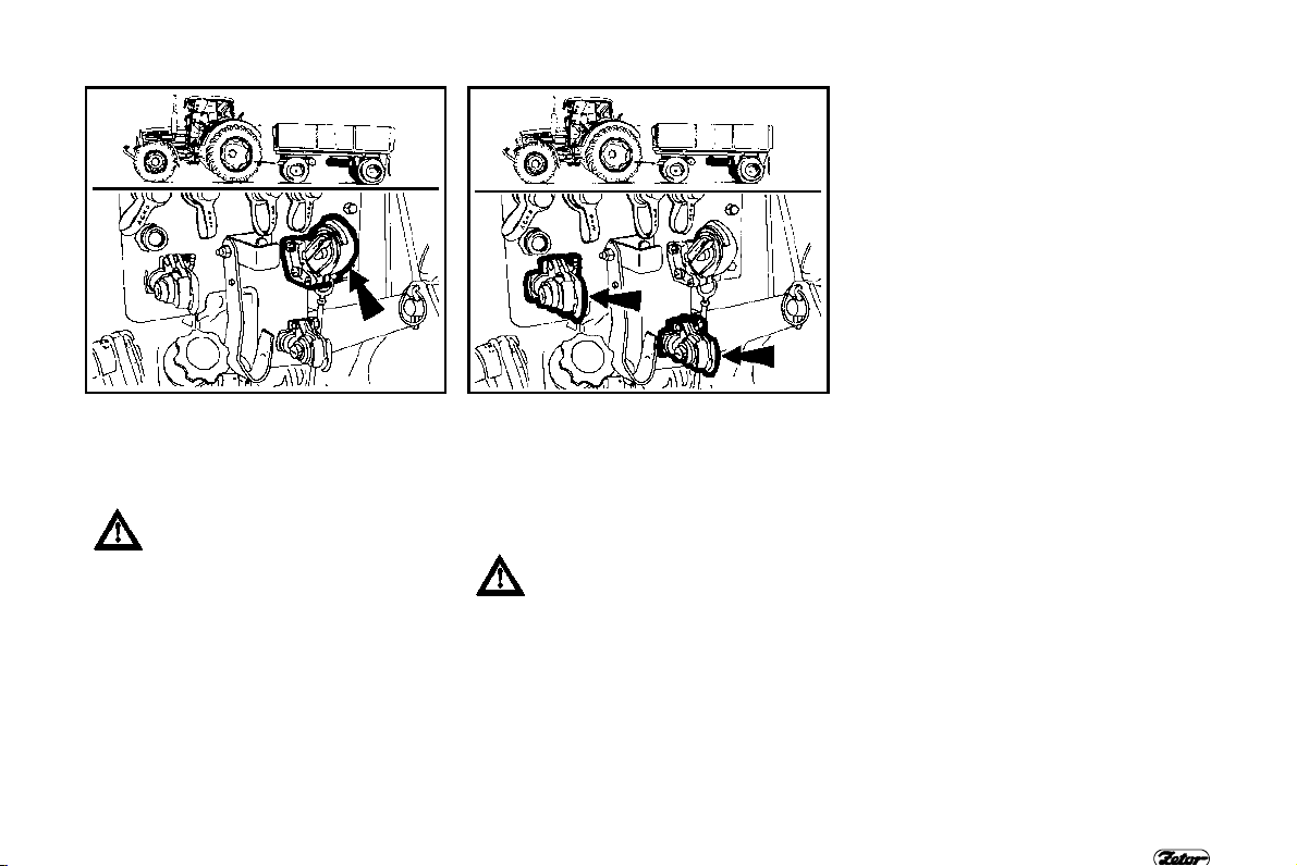
F 112 F 113
SINGLE HOSE AIR TRAILER BRAKES
Operating pressure is set by a pressure
valve (regulator) adjusted to 600 20
kPa. Capacity of both air tanks is 24
The allowed speed of tractor
equipped with single hose air
trailer brakes and with hitched
trailer is max. 25 km/h.
l.
OPERATION
DOUBLE HOSE AIR TRAILER
BRAKES
Operating pressure is set to 740 20
kPa Capacity of air tanks is 24 l. Left
coupling cover is yellow, right coupling
cover is red.
The allowed speed of tractor
equipped with double hose air
trailer brakes and with hitched
trailer is max. 40 km/h .
77

OPERATION
F 114
HYDRAULIC TRAILER BRAKES
Hydraulic trailer brake control is synchronized with braking the tractor including the
braking effect. Operating pressure is activated by pressure of oil from hydraulic
pump (1). The hydraulic valve (2) is introduced in the circuit of hydraulic pump. The
hydraulic pump is of gear type (pump can not be disengaged).
The hydraulic trailer brake valve is controlled by the brake fluid pressure activated in
master brake cylinder depending upon the force on brake pedal. The pressure in
brake coupling (4) must be 12 - 15 MPa at maximal press on the brake pedal. Trailer
brake valve prioritizes the function of brake to control of hydraulic. Do not forget to
bleed the trailer brake valve (2) by vent screw (3) when bleeding the service brakes.
In case there are hydraulic shocks in hydraulic circuit if applied service brake pedals
it is necessary to bleed the hose (5) coming from brake valve (2) to quick-coupler
(4).
78
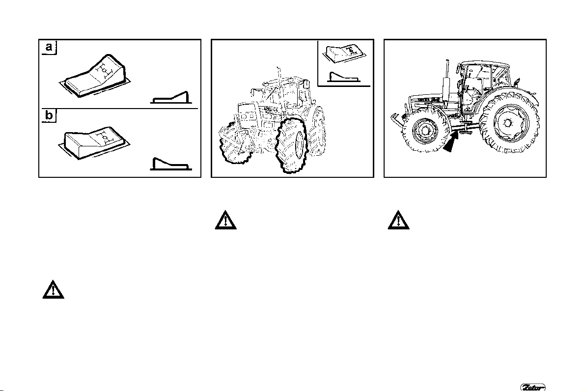
F 116 F 117 F 117a
CONTROL OF FRONT DRIVING AXLE
Front driving axle is engaged in basic
position (indicator lamp is “ON„). It is
disengaged by a switch on the
dashboard.
a -
Front axle is disengaged
b - Front axle is engaged
Front driving axle is engaged at stopped
tractor (stopped tractor, stopped engine).
At tractors with pin diff. lock of
front driving axle the differential
lock must not be locked when
driving on the road! Danger of
accident when turning!
OPERATION
DRIVING WITH ENGAGED FRONT
DRIVING AXLE
Use the front driving axle when
slipping the rear wheels and for
increasing the traction force.
Driving with engaged front diving
axle on the road and hard
surface causes an excessive
wear of front tires.
Permanent engagement of front driving
axle is possible if a front agriculture
machine or implement is attached to the
tractor. This is specified in operatorřs
manual of a particular machine.
Maximal allowed speed of tractor with
such attachment is 15 km/h.
FREE SPACE ROUND CARDAN
SHAFT
Ensure the free space minimally
10 mm round cardan shaft when
assembling aggregates or attaching implements. This space
must be round the whole length
of cardan shaft within any its
inclinations.
If this rule is not fixed, danger of
tractor damage or machine accident is possible!
79

F 118 F 119 A 120
STOPPING THE TRACTOR - PARKING
BRAKE
At normal conditions stop the tractor
gently and slowly.
Shortly before stopping:
Depress the clutch pedal
1.
2. Move the main shifting lever into
neutral
3. At each tractor stopping set the
parking brake and so protect the
tractor against accidental movement.
Indicator lamp located on the dash
indicates parking brake setting.
OPERATION
STOPPING THE ENGINE
Engine must be cooled after work with
fully loaded tractor.
1. First reduce the engine speed to 800
- 1000 RPM before stopping the
engine and let it run without load
approximately for 5 minutes.
2. Move the throttle control lever into
STOP position.
3. Pull up the stopping device and keep
it in pulled position up to stopping the
engine.
At tractors Z 11641 with electronic governor the engine is stopped by turning the key in key
switch into “0“ position.
LEAVING THE TRACTOR
Key can be turned from "I" position into
"0" position at stopped tractor only
indicator lamp of charging must be ON.
Tractor must be properly assured
against accidental moving when on the
hill: braked, with engine “off “, reverse
gear shifted and with low gear shifted by
main shifting lever Wheels must be
locked by blocks.
Remove the key from the key
switch and lock the cab at cab
tractors before leaving.
80

NOTE
81

NOTE
82

TRACTOR RUNNING IN
Page
General rules for running in the new tractor within first 100 hours
First 10 hours ................................................................................................ ............ 84
After 10 hours............................................................................................................ 85
After 10 hours............................................................................................................ 85
After 50 hours............................................................................................................ 85
After 70 hours............................................................................................................ 86
After 70 hours............................................................................................................ 86
After 70 hours............................................................................................................ 86
After 100 hours................................ .......................................................................... 87
After 100 hours................................ .......................................................................... 87
............................ 84
83

GENERAL RULES FOR RUNNING IN
THE NEW TRACTOR WITHIN FIRST
100 HOURS
Within the first 100 operating hours:
load the engine normally
-
- avoid the partial engine load at
operation
- avoid the long operation at low idle
- frequently inspect the engine oil level
(the increased oil consumption is
normal in this time)
- check the hardware connections
especially connections of highly
stressed parts of the tractor
- immediately remove all found
problems. You will avoid subsequent
damage eventually even traffic hazard
TRACTOR RUNNING IN
F 121 F 122
- use a similar process also after
general repair of engine.
84
FIRST 10 HOURS
- run in the tractor at transport
operating
- tighten front and rear wheel nuts by
prescribed torque

TRACTOR RUNNING IN
F 123 F 124 F 125
AFTER 10 HOURS
We recommend to drain or suck off the
preheated oil from transmission and to
filter it by means of filtration device with
filtration capability 20 ’ m.
Transmission is equipped with 5 draining
openings (1x clutch housing, 1x gearbox,
3x differential housing).
AFTER 10 HOURS
Remove and clean the magnetic
element (1) and strainer element of
transmission oil suction cleaner (2).
Wash both elements in petrol and
reassemble after dripping. If necessary
add the oil up to the upper mark of
dipstick (3). Now you can use the
complete hydraulic system of tractor
without restrictions.
85
AFTER 50 HOURS
At tractors Z 11641 drain the hot
running in oil from engine and
exchange the full-flow engine oil
filter. Fill in the engine with new oil to the
prescribed level - upper mark of oil
dipstick (inspects after engine cranking
and oil level stabilizing). It is necessary
to let the engine run few minutes before
refilling the oil.

TRACTOR RUNNING IN
F 126 F 127 F 128
AFTER 70 HOURS
At tractors Z 8621 - 10641drain the hot
oil from engine and exchange the fullflow engine oil filter. Fill in the engine
with new oil to the prescribed level
(upper mark of oil dipstick - inspect it
after cranking the engine and stabilizing
the oil level). It is necessary to let the
engine run few minutes before refilling
the oil.
AFTER 70 HOURS
Check the
cold engine, by prescribed torque in
prescribed sequence of screws).
torque of cylinder head (at the
Do checking, adjustment, head retigh-
tening and adjustment of valve
clearance in an authorized service.
86
AFTER 70 HOURS
Remove and clean:
- magnetic element of transmission
suction filter (1)
- strainer element of transmission oil
suction cleaner (2)
Exchange:
- paper element of full-flow fine cleaner
(3)
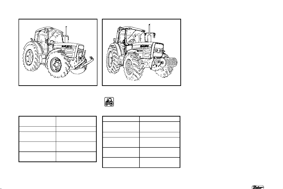
F 129 F 130
AFTER 100 HOURS
After running in you can work with the
tractor without any restrictions.
The operating regime at tractors Z 8621
- Z
10641:
recommended
operating speed 1400 - 2300 RPM
low idle speed 700 - 650 RPM
operating oil
pressure
oil pressure at
low idle speed min. 0,05 MPa
coolant
temperature
0,2 - 0,5 MPa
80 - 95“C
TRACTOR RUNNING IN
AFTER 100 HOURS
After running in you can work
with the tractor without any
restrictions. The operating regi-
me at tractors Z 11641:
maximal speed 2350 RPM
recommended
operating speed 1400 - 2450 RPM
low idle speed 700 „ 10 RPM
operating oil
pressure
oil pressure at
low idle speed
coolant
temperature
0,35 MPa
min. 0,05 MPa
80 - 100“C
87

NOTE
88

NOTE
89

NOTE
90

Before driving be sure that the
tractor technical status corresponds to the safe traffic
requirements. Verify hitching the
trailer and fixing the transported
load if attached trailer or agricultural implement. Never leave
the tractor being in move for
attaching the trailer yourself.
Keep also safety of your assistant
TRANSPORTATION
Strana
Front hook
Trailer hitch ................................................................ ............................................... 92
Mechanical mouth of trailer hitch ................................................................ .............. 92
Automatic mouth of trailer hitch................................................................................. 93
Swinging drawbar...................................................................................................... 93
Pick up hitch combined with drawbar ........................................................................ 94
Exchange of hook for drawbar .................................................................................. 94
Drawbar of combined pick up hitch ........................................................................... 94
Mechanical unlock of carrier hooks ........................................................................... 95
Hydraulic unlock of carrier hooks .............................................................................. 95
Drawbar..................................................................................................................... 96
Trailer implementation................................................................ ............................... 96
................................................................ ................................................. 92
91

F 132 F 133 F 134
FRONT HOOK
Front hook is used only for pulling the
tractor that is without any attached trailer
or implements.
Use the pull bar or rope when
releasing the tractor. Never use
chains!
Hazard of dead injury when the
chain is interrupted!
At tractors Z 11641 the front
hook is a part of ballast weight
support.
Note: When assembled front ballast
weight, the pin of front canister weight
can be used for emergency releasing the
tractor.
TRANSPORTATION
TRAILER HITCH
Trailer hitch is used for attaching the
four-wheel trailers or light two-wheel
trailers. The trailer hitch is height adjustable in 3 positions by 100 mm. When
working with different agricultural machines it is often necessary to adjust, tilt, or
eventually remove the hitch with support.
MECHANICAL MOUTH OF TRAILER
HITCH
Hitch pin diameter is 30 mm. Maximal
vertical static load is 10 kN.
92
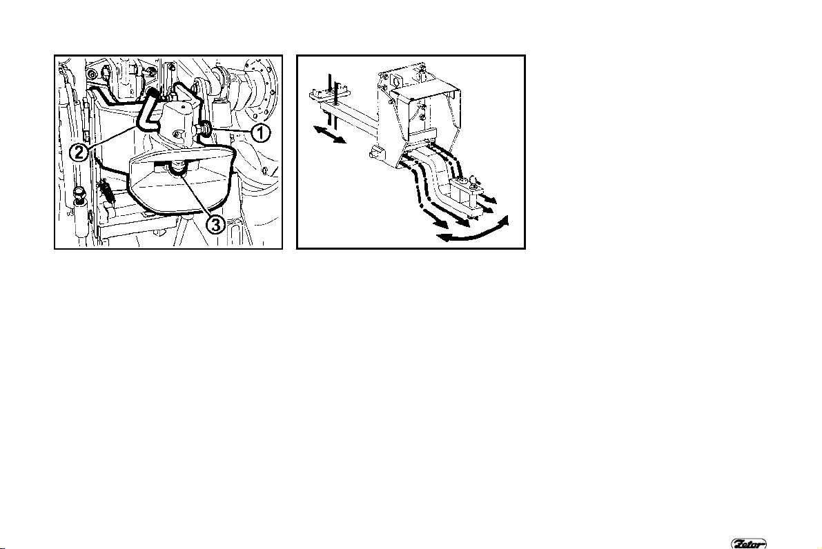
F 135 F 136
AUTOMATIC MOUTH OF TRAILER
HITCH
For attaching the trailer do the following pull out the latch (1) and simultaneously
raise the main hitch pin (3) into its upper
position by means of lever (2). Pin
automatically slides into trailer yoke eye
after coupling the mouth and yoke. Be
sure the latch is back in position after
coupling trailer.
Maximal allowed vertical static load is 10
kN.
TRANSPORTATION
SWINGING DRAWBAR
Swinging
side in 5 positions by 80 mm. Drawbar is
fixed by the clevis in desired position.
The drawbar can be longitudinally set in
two positions - measured from the end of
PTO shaft (350 or 400 mm).
Cross bar above the drawbar enables an
operation with implements requiring the
floating position of swinging drawbar
(with disassembled clevis)
Maximal vertical static load of drawbar
clevis is 12 kN.
drawbar can be set side to
93
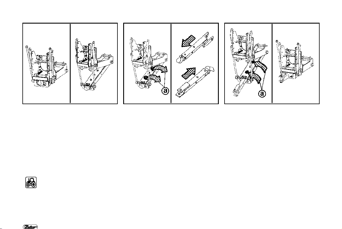
F 138 F 139 F 140
PICK UP HITCH COMBINED WITH
DRAWBAR
Pick up hitch is intended for coupling the
two-wheel trailers with yoke corresponding to ISO 5692 (the internal yoke
eye diameter is 50 mm and eye height is
30 mm). Pick up hitch hook is hydraulically raised and lowered by means of
length adjustable telescopic links.
The allowed vertical static load of hitch is
24 kN at tractors Z 8621 - 10641.
The allowed vertical static load of
hitch is 30 kN at tractors
11641.
Z
Pick up hitch is capable for pulling the
maximal traction force.
TRANSPORTATION
EXCHANGE OF HOOK FOR DRAWBAR
The hitch is also equipped with drawbar
that is in the opposite side of hitch hook.
Drawbar can have three working
positions. Change of hitch hook for
drawbar is carried out by lowering the
hitch hook carrier into position suitable
for removing pins (a). Afterwards the
hitch hook is removed from the carrier
and inserted into such position that the
swinging drawbar clevis is in front of
carrier.
DRAWBAR OF COMBINED PICK UP
HITCH
Maximal vertical static load is 12 kN.
Drawbar is capable for pulling the
maximal traction force of tractor.
94
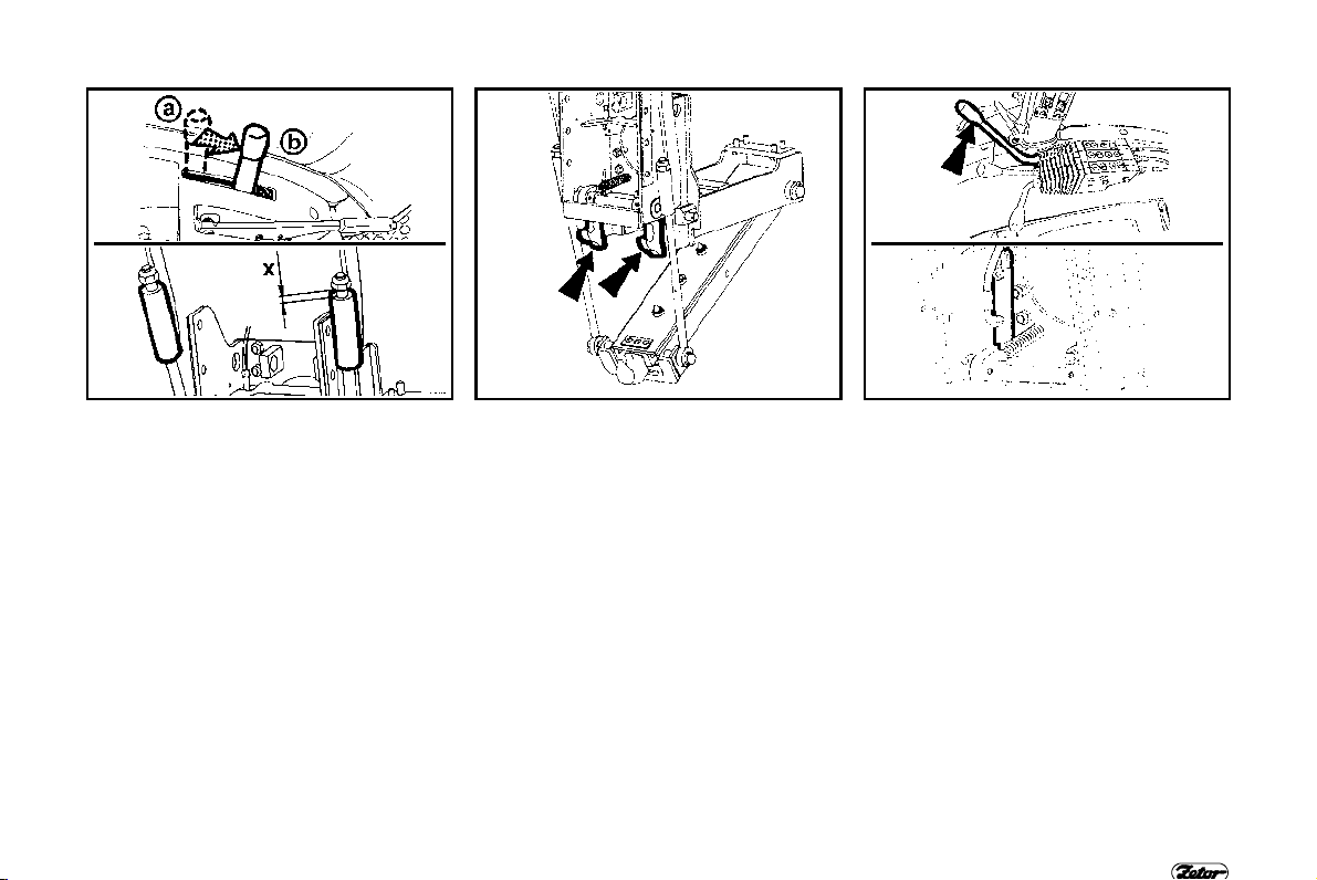
F 141 F 142 F 143
MECHANICAL UNLOCK OF CARRIER
HOOKS
Carrier hooks are unlocked by lever
located on the left hand side of driver’s
seat.
a -
transport position
b - hook of hitch is unlocked (lowered)
1. Lift hydraulic arms into the upper
position (with position control)
2. Move the pick up hitch control lever
into position (b) and keep it.
3. Lower hydraulic arms into low
position “ release the lever of pick up
hitch control within lowering operation “ it comes back into its
previous position.
4. Attach or disattach the trailer.
5. Lift hydraulic arms into upper posi-
tion.
TRANSPORTATION
6. Hooks snap under pins; afterwards
lower hydraulic arms a little.
7. Telescopic links must not be
stretched! Keep the minimal play
(x)!
95
HYDRAULIC UNLOCK OF CARRIER
HOOKS
At tractors equipped with ∗ hydraulic
control of pick up hitch the pick up hitch
lowering is controlled by selective control
valve lever (usually right SCV lever or
according to operator’s choice).
1. Lift hydraulic arms into the upper
position (with position control).
2. Apply pressure oil into quick-coupler
where the hydraulic cylinder is
connected. Carrier hooks are
unlocked by this way and
subsequently return the lever into its
neutral position.
3. Lower rear three point hitch into its
low position.

F 143a F 144 F 145
4. Apply the back-pressure into hydraulic cylinder within lowering operation. Carrier hooks come back into
their operating position by this way.
Than return the lever into neutral
position.
5. Attach or disattach the trailer.
6. Lift hydraulic arms into upper position.
7. Hooks snap under pins;
8. Lower hydraulic arms a little.
9. Telescopic links must not be
stretched! Keep the minimal play
(x)!
TRANSPORTATION
DRAWBAR
Drawbar is height adjustable by the
hydraulic lifting system within its hole
lifting range. Only agricultural implements loading permanently the drawbar
downwards can be attached to the
drawbar. Maximal vertical static load is 8
kN.
Disassemble the trailer hitch with
support when working with the
drawbar.
TRAILER IMPLEMENTATION
Tractor must be implemented only with
suitable tractor trailer because tractor
service brakes and air brakes of trailer
must match together.
Static rear axle load must not exceed the
max. allowed axle load of tractor when
implemented with two wheel trailer.
96

TRANSPORTATION
Type
Allowed vertical
static load
10 kN 12 kN
12 kN 5 kN
24 kN
30 kN
Type
Maximal weight of implemented braked trailer must not
exceed value mentioned in warning tractor label and
value mentioned in a technical license of vehicle.
Maximal speed of implemented tractor is given by
max. allowed speed of slower vehicle.
Allowed vertical
static load
97

TRANSPORTATION
Allowed load of pick up hitch at tractors Z 8621, Z 8641, Z 9621, Z 9641, Z 10641, Z 11641. Values are valid for tractor with front
ballast weight according to the table, without ballast weight of rear wheels, at max. allowed load of rear axle
F
Speed
(km/h)
8
20
30
Tire
(kN)
16,9-34
18,4-34
16,9-38
16,9-34
18,4-34
16,9-38
18,4-38
18,4-38 28
18,4-38 30
16,9-34
18,4-34
16,9-38
16,9-34
18,4-34
16,9-38
18,4-38
18,4-38 24
Tractor Type Tractor equipment
Ballast weights (pcs) = total weight of ballast weights - kg
Weight in front of frame (1+2) = 90 kg
Under-frame weight (1+3) = 120 kg
without ballast weight of rear wheels
Under-frame weight (1+3) = 120 kg
Weight in front of frame (1+7) = 240 kg
without ballast weight of rear wheels
Under-frame weight (2) = 96 kg
Front weight (weight support + 14) = 619 kg
without ballast weight of rear wheels
Front three point hitch + weight (16) = 456 kg
without ballast weight of rear wheels
Weight in front of frame (1+2) = 90 kg
Under-frame weight (1+3) = 120 kg
without ballast weight of rear wheels
Under-frame weight (1+3) = 120 kg
Weight in front of frame (1+7) = 240 kg
without ballast weight of rear wheels
Under-frame weight (2) = 96 kg
Front weight (weight support + 14) = 619 kg
without ballast weight of rear wheels
18
27
10
18
Z 8621
Z 9621
Z 8641
Z 9641
Z 10641
Z 11641
Z 11641
Z 8621
Z 9621
Z 8641
Z 9641
Z 10641
Z 11641
Front PTO
98

TRANSPORTATION
Speed
(km/h)
F (kN)
20
30
40
Tire
18,4-38 25
16,9-34
18,4-34
16,9-38
16,9-34
18,4-34
16,9-38
18,4-38
18,4-38 24
18,4-38 25
- Allowed load of pick up hitch
F
(kN)
-
18
Tractor Type Tractor equipment
Z 11641
Z 8621
Z 9621
Z 8641
Z 9641
Z 10641
Z 11641
Z 11641
Ballast weights (pcs) = total weight of Ballast weights - kg
Front three point hitch + weight (16) = 456 kg
Front PTO
without ballast weight of rear wheels
Weight in front of frame (1+2) = 90 kg
Under-frame weight (1+3) = 120 kg
without ballast weight of rear wheels
Under-frame weight (1+3) = 120 kg
Weight in front of frame (1+7) = 240 kg
without ballast weight of rear wheels
Under-frame weight (2) = 96 kg
Front weight (weight support + 14) = 619 kg
without ballast weight of rear wheels
Front three point hitch + weight (16) = 456 kg
Front PTO
without ballast weight of rear wheels
99

NOTE
100
 Loading...