


ZETOR
This Operator’s Manual for the Zetor Forterra tractors, which we are presenting to you will help you to become
familiar with the operation and maintenance of your new tractor.
Although many of you have rich experience with the operation of other tractors, please, read the information
contained in this Operator’s Manual very carefully.
In the Manual you will find a lot of new information and get a perfect overview of how to use the tractor with
maximum efficiency during various kinds of work.
If you observe the rules of tractor operation and maintenance and driving safety, your new tractor will become your
reliable and long-term friend.
The manufacturer of the tractor wishes you thousands of hours of satisfactory work.
ZETOR
Brno
3

The technical specifications and information about the design, equipment, material and appearance are valid at the time of print.
The manufacturer reserves the right to implement changes.
4

The Operator’s Manual deals with the
description, operation and maintenance
of the standard version and accessories
that the tractor may be optionally
equipped with.
The service cheque book for tractors is
not part of the Operator’s Manual, but
forms a separate booklet that is handed
over to you at the purchase of your new
tractor.
CONTENTS
Page
Location of serial numbers ......................................................................................... 7
Safety instructions for users........................................................................................9
Preventive daily maintenance ................................................................................... 13
Acquaintance with the tractor ................................................................................... 19
Driving operation ....................................................................................................... 47
Running in the tractor ............................................................................................... 65
Transportation ........................................................................................................... 69
Drive of agricultural machines .................................................................................. 75
Hydraulic system ......................................................................................................81
Electro-hydraulic system ........................................................................................... 89
Hitches ...................................................................................................................... 99
Wheel track change ................................................................................................ 107
Ballast weights ........................................................................................................ 113
Electric installation ..................................................................................................121
Tractor maintenance ...............................................................................................131
Maintenance instructions......................................................................................... 145
Adjustment ............................................................................................................. 167
Main technical parameters ..................................................................................... 177
Index ......................................................................................................................191
5
Zetor Forterra 95........................... 66 kW
Zetor Forterra 105......................... 74 kW
Zetor Forterra 115 ......................... 81 kW
Zetor Forterra 125......................... 90 kW
ZETOR FORTERRA TRACTORS
6
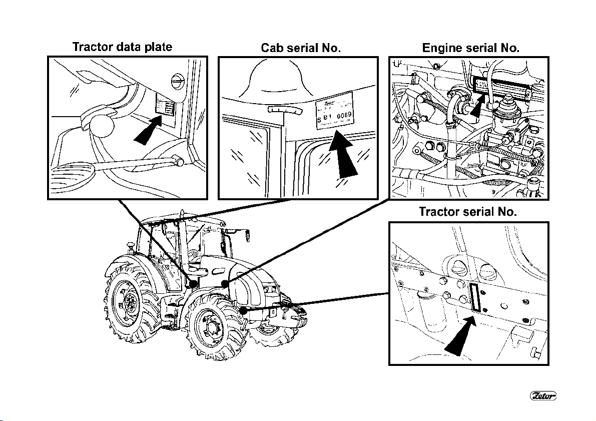
LOCATION OF SERIAL NUMBERS
XH154
7
LOCATION OF SERIAL NUMBERS
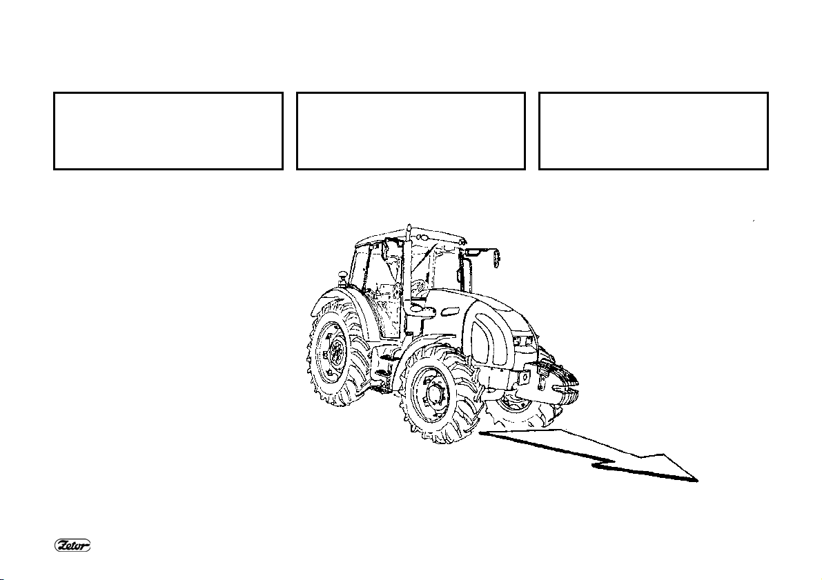
When ordering spare parts and within all written and oral communication always specify the data of your tractor that should be
written in the frames below.
Tractor type
Zetor Forterra 95
Zetor Forterra 105
Zetor Forterra 115
Zetor Forterra 125
The “right”, “left”, “front” and “back”
indications refer to the driving direction of
the tractor.
The manufacturer reserves the right to
implement changes of the design and
options during the production to improve
the features of the tractor.
Tractor serial number
8
Engine serial number
XF-02-101
SAFETY INSTRUCTIONS FOR USERS
Please, pay increased attention to the
parts of the Operator’s Manual that are
marked with this symbol.
This symbol accompanies all
important warnings that concern
operation safety.
Observe these instructions
and be extremely careful in
these cases!
Inform your colleagues and
other users about these
warnings.
Carefully study the chapters
marked with this symbol before
starting to perform operation,
repairs and adjustments of your
tractor.
This symbol identifies all
important information concerning
operation, adjustment and
repairs of the starter motor.
Observe these instructions
and be extremely careful in
these cases!
This symbol marks parts of the
Operator’s Manual concerning
environment protection. Or
possibly sections describing
handling of dangerous waste.
This symbol refers to optional
∗
tractor accessories installed by
the manufacturer on the
customer’s request.
Accessories that are not
installed by the manufacturer in
the standard way or * optionally
on the customer’s request (in the
production plant) cannot be
subject to a claim.
GENERAL SAFETY REGULATIONS
1. The tractor may only be operated by
a trained person that has a valid driving
licence and has been thoroughly
acquainted with the operation and safety
rules.
2. Besides the safety instructions
mentioned in the Operator’s Manual you
are obliged to respect generally valid
safety and traffic rules of the country
where the tractor is used.
PROPER CLOTHING
3. Do not wear loose clothing and free
flying long hair.
4. During all work use suitable
(prescribed) means of personal
protection (working boots, gloves,
goggles, etc.)
9
STARTING THE ENGINE
5. It is not permitted to start the engine
by driving down a slope.
6. The tractor may be put in motion to
start the engine with the use of another
tractor or another vehicle with the use of
a towing bar only.
7. Only start the engine from the driver’s
seat with the clutch pedal fully
depressed.
Life hazard when starting by
means of short-circuiting the
starter terminals!
8. The key in the switch box must be in
the “I” position.
9. When heating the engine with the *
electric heater first plug the power supply
cord to the heater and only then to the
electric mains. After the end of heating
first disconnect the heater from the
electric mains.
Caution! Electric shock hazard!

SAFETY INSTRUCTIONS FOR USERS
DRIVING OPERATION
10. Hoses of the hydrostatic steering,
brakes and fuel system must be checked
and replaced immediately if any signs of
damage are found. These are some
examples of hose damage signs: cracks on the hose surface, releasing of
pre-tensioning of hose connection (which
can be verified by easy removal of the
hose from the connection) and
mechanical damage of the hose. Hoses
with indicated service life must be
replaced immediately after the expiration
of the service period.
11. If the tractor uses bio-fuel, the fuel
system must be equipped with REP
hoses (the fuel system is equipped with
REP 6 hoses by the manufacturer).
12. The brakes and steering must be in
the perfect condition all the time.
13. During driving on roads with trailers
and tools the brake pedals must be
connected with a latch.
14. Driving downhill without an engaged
gear is forbidden.
15. Pay special attention when driving on
a slope and muddy, sandy, icy or uneven
ground.
16. Observe the maximum prescribed
slope gradient of 12°.
17. Respect the total permissible weight
of the tractor and trailer specified on the
data plate of the tractor or on the rear
wheel mud-guard.
18. Do not use the differential lock when
driving into a bend.
19. It is forbidden to get into and out of a
moving tractor.
20. When driving with machines attached
to the rear hitches the load of the steered
axle must not drop below 18 % of the
current weight of the set.
21. When driving the tractor with
agricultural machines attached to the
front three-point hitch, reduce the driving
speed to 20 km/h.
22. During aggregation of Zetor Forterra
tractors with machines and implements
with high tensile resistance when the
engine speed drops and the engine
tends to stall, the 1R, 2R reduced gears
must not be used for the work with these
machines (risk of shaft twist-off). .
TRANSPORTATION OF PERSONS,
OPERATION
23. The number of persons transported
by the tractor must not exceed the
number specified in the technical
certificate of the tractor.
24. Persons that are not authorized to
work with the attached implement must
not stand between the tractor and the
hitched machine (implement).
25. Before putting the tractor in motion
10
make sure there is no person or obstacle
in the driving direction.
26. Observe the prescribed slope
gradient, which has the value of 12° for
the Zetor Forterra 95, 105, 115, 125
tractors.
RECOVERY, PUSHING
27. To recover a tractor that has sunk in
mud use a tow bar or rope attached to
the front hook.
Never use chains! Rupture of
the chain represents a danger
of death!
28. During recovery it is dangerous to
stand near the towing rope.
29. It is prohibited to use the tractor axles
(individual wheels) as a winch for
releasing a sunken tractor.
30. The front hook should be only use to
recover the entire tractor, i.e. without any
trailer or another attached implement.
31. Never recover the tractor with
reduced gears engaged.
32. When pushing other vehicles
(trailers, implements, etc.) with the
tractor never insert free wooden blocks
or bars between the tractor and the
pushed vehicle.
LEAVING THE TRACTOR
33. Do not park the tractor with an
attached implement in the lifted position.

SAFETY INSTRUCTIONS FOR USERS
34. Before leaving the tractor do not
forget to brake the tractor with the
parking brake (by engaging a gear).
Remove the key from the switch box and
lock the cab.
35. In the case of a tractor equipped with
reversing shift the reversing lever to the
forward position.
36. Before leaving the tractor with the
engine running brake the tractor with the
parking brake.
37. To get out of the tractor normally use
the left side of the tractor. Look around
to see whether a vehicle is coming that
could endanger your safety during
getting off and only then open the door.
38. When leaving the tractor use the
steps and handles. Pay increased
attention in the area of the shifting lever
and the manual throttle lever as well as
the upper step.
WITH STOPPED ENGINE ONLY
39. All work connected with refuelling,
cleaning, lubricating and adjusting the
tractor or attached implements may only
be performed with the engine and
moving parts of the tractor stopped
except functional checks of the brakes,
hydraulic system and charging.
40. Before removing the side plates of
the hood it is always necessary to stop
the engine. The tractor engine can only
run in a closed building or room if
sufficient ventilation is ensured. Exhaust
gases are harmful for health.
FIRE PREVENTION PRINCIPLES
41. Refuel the tractor best after the end
of work and with the engine stopped.
42. Do not refill fuel up to the top of the
fuel tank in summer. Wipe spilt fuel
immediately.
43. Do not refuel the tractor near open
flame and do not smoke.
44. Do not smoke and do not use open
flame when inspecting the battery
electrolyte level.
45. Make sure that fire safety instructions
are strictly observed in environments with
an increased danger of fire (hay-lofts,
straw-stacks, etc.).
46. The tractors are not equipped with a
fire extinguisher from the production
plant.
HEALTH AND ENVIRONMENT
PROTECTION
47. The tractors are not equipped with
special filters of air aspirated to the cab.
Therefore, they are not designed for
work with aerosols and other harmful
substances.
48. Coolant, brake liquid, kerosene,
diesel fuel, mineral oil and other oil
products that are used for the operation
11
and maintenance of the tractor may
cause various skin disorders in case of
direct contact with your skin and can
irritate mucous membranes, eyes, the
digestive system and upper respiratory
ways. Some of them may even cause
systemic poisoning when swallowed.
49. Persons that handle oil products are
obliged to strictly observe safety and
hygienic regulations, use suitable means
of protection and work in well-ventilated
rooms.
WORKING WITH OIL
PRODUCTS
50. After the end of work or before a
meal you should wash yourself with a
mild agent and treat your hands with a
suitable ointment or cream.
51. When connecting and disconnection
quick-couplers of the hydraulic circuits
use any piece of cloth to remove residual
oil remaining in the socket or on the plug
of the quick-coupler.

SAFETY INSTRUCTIONS FOR USERS
WASTE DISPOSAL
52. When disposing of the tractor or its
parts (incl. operation liquids) after the
end of their service life you must observe
relevant provisions of valid acts and
implementation directives of these acts
of the country where the tractor is used.
The last seller of the tractor is obliged in
accordance with the Waste Act to inform
the consumer - during the sale of the
tractor - about the way of collection of
some used parts of the tractor. This is
the case of oil and other operation
liquids, batteries and tyres. These used
products must be received from the
consumer without any obligation of the
consumer to pay for this service.
PREVENTIVE DAILY MAINTENANCE
53. Perform this maintenance daily or
after every 8 - 10 hours of operation at
the latest.
SAFETY CAB
54. If the protective frame of the safety
cab is damaged by corrosion, an
accident or otherwise, the safety cab
must be replaced.
AIR-CONDITIONING
55. Disassembling, turning or otherwise
handling the screw union of the airconditioning system is not allowed in any
case. Sudden leak of the coolant may
occur, causing quick local cooling.
Contact or freezing of components in
hands may cause serious damage of
some tissues.
56. The air-conditioning system is
equipped with quick-couplers that make
it possible to separate the cab from the
tractor body if necessary without any
coolant leak. Entrust interventions into
the air-conditioning system to a
specialized repair shop.
ELECTRIC INSTALLATION
57. No additional interventions
into the electric installation
(connection of other electric
appliances) are permissible due
to its possible overloading!
58. The values of the electric installation
are:
Nominal voltage 12 V =
Grounded minus
pole
Using starting trucks or auxiliary power
supplies with a different voltage or
polarity may cause serious failures of the
tractor.
( - ) pole
12
59. When handling the battery you must
pay increased attention and avoid shortcircuits. In tractors equipped with a
battery disconnector switch the
disconnector off when handling the
battery.
60. Zetor Forterra tractors must not be
operated with a disconnected battery as
this may lead to a serious failure of the
tractor.
PREVENTIVE DAILY MAINTENANCE
Perform this maintenance daily or after every 8 - 10 hours of operation at the latest.
13
XF_02_148
PREVENTIVE DAILY MAINTENANCE
F_02_192 XF_02_193 F_02_3a1
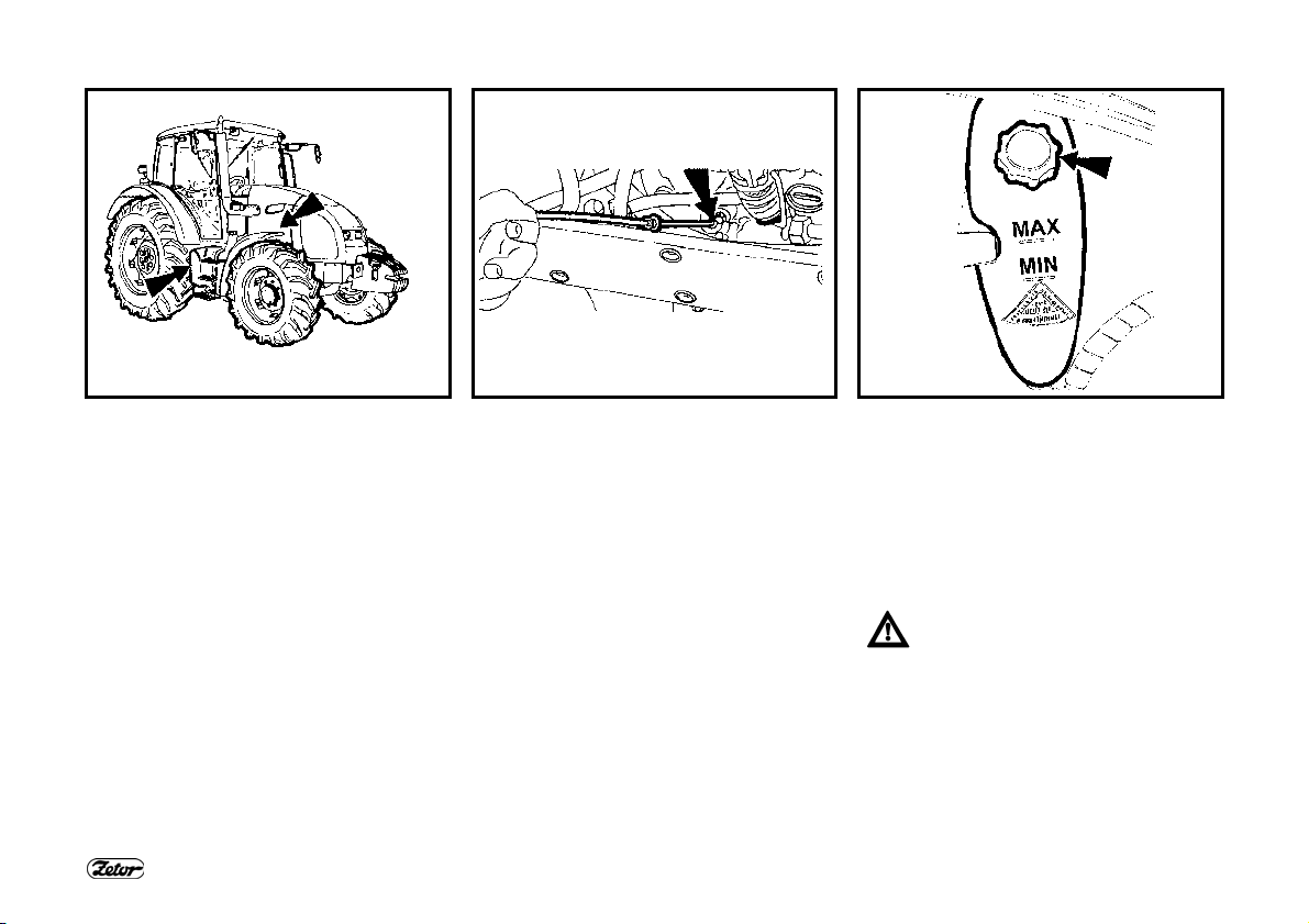
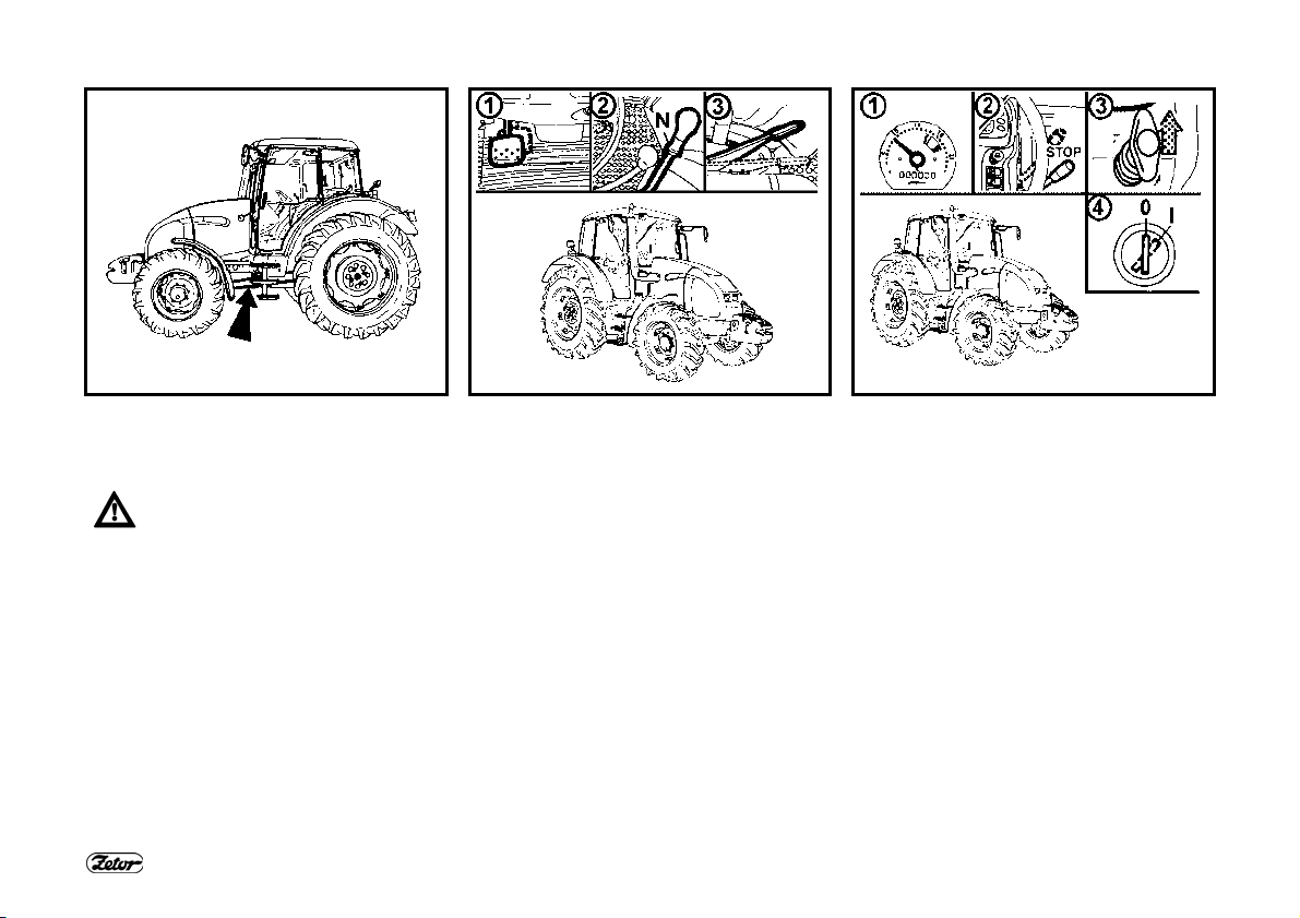
FUEL SYSTEM LEAKS
Check the fuel system for leaks,
including the fuel tank. Repair any leaks
immediately. The hole for draining dirt
from the fuel tank is found in its bottom.
ENGINE OIL LEVEL
After unscrewing and removing the oil
dip-stick check the oil quantity in the
engine and then check the connection of
the engine lubrication system for leaks.
Maintain the oil level between the dipstick marks.
14
COOLING SYSTEM
Check the connections of the engine
cooling system for leaks and the coolant
quantity in the expansion tank.
Replenish the missing quantity up to the
upper mark indicated MAX. The
minimum acceptable cooling liquid level
is indicated by the MIN mark.
Only release the overpressure
plug when the coolant has cooled
down! There is a danger of
scalding!
PREVENTIVE DAILY MAINTENANCE
F_02_4 F_02_56 F13
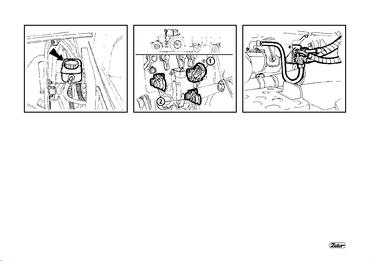
LIQUID BRAKES
Check the liquid brakes for leaks as well
as the liquid control of the clutch and the
braking liquid level in the expansion tank.
Maintain the brake liquid level in the
range of 3/4 of the tank content (max.
level) and 1/2 of the tank content
(minimum level).
TRAILER AIR BRAKES
Check the air system of the brakes for
leaks and the efficiency of the tractor
brakes with a trailer (see the
Maintenance instructions chapter; the
Checking the air systems for leaks
section of this Operator’s Manual).
TRAILER HYDRAULIC BRAKES
Check the hydraulic brakes of the trailer
for leaks.
15
PREVENTIVE DAILY MAINTENANCE
D402 F_02_6a F_02_9
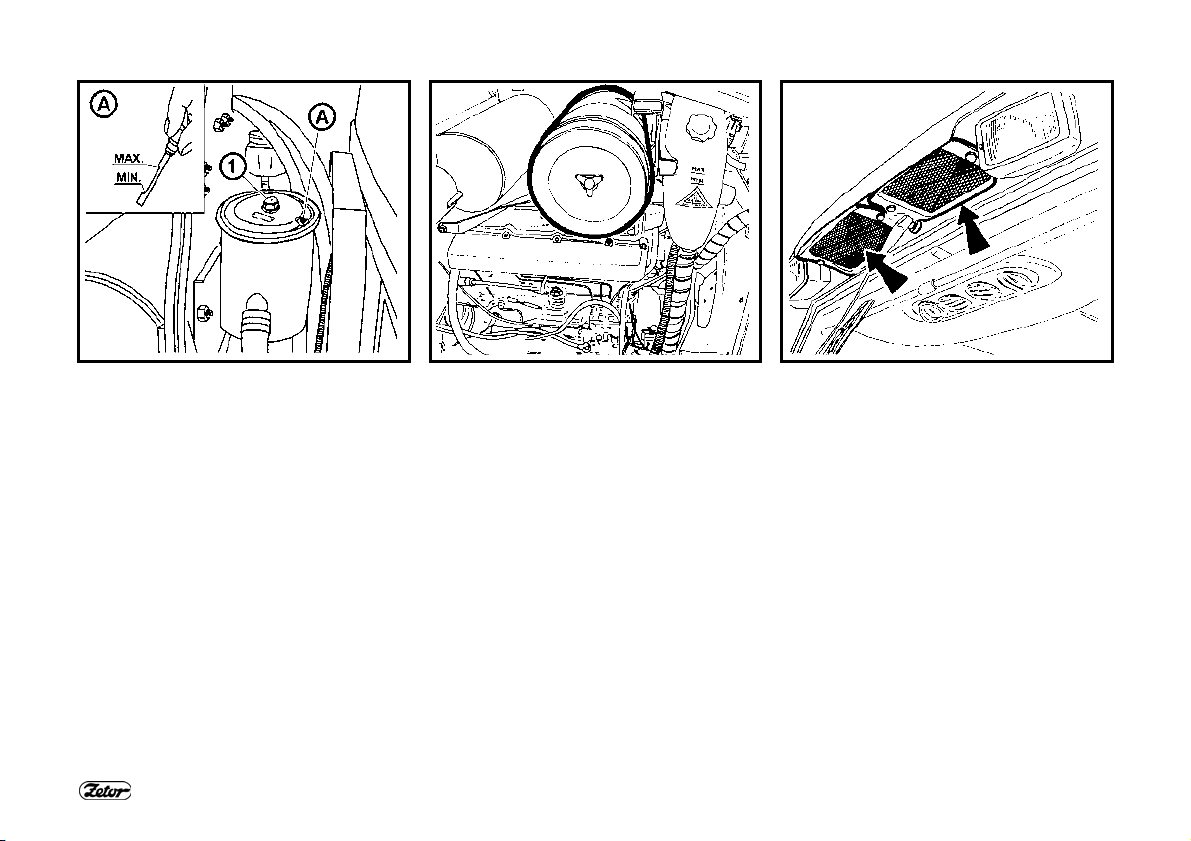
HYDROSTATIC STEERING
- Check the oil level in the hydrostatic
steering tank.
- Check the tightening of screws and
nuts of the steering rods and levers.
- Check the condition of all the hoses of
the hydraulic steering circuit for
damage and for oil leaks.
AIR CLEANER
If the air cleaner is heavily clogged with
dirt, this condition is indicated by a
sensor that lights up an indicator on the
dashboard.
16
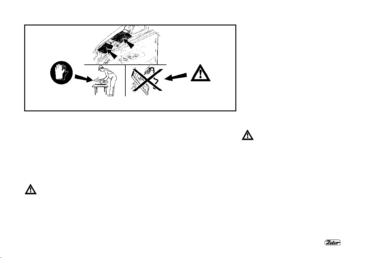
CAB FILTRATION
Check and if necessary clean the cab
ventilation air filters installed in the front
overhang of the roof.
The filter exchange interval depends on
the dustiness of the working
environment.
Partial regeneration can be performed by
beating out or blowing with compressed
air.
Do the cleaning or replacement of the
filter elements after removing the
covering grills in the roof overhang.
PREVENTIVE DAILY MAINTENANCE
F18 F_02_100 F_02_7
HITCHES
Check the condition of the hitching and
attachment systems of the tractor and
trailer.
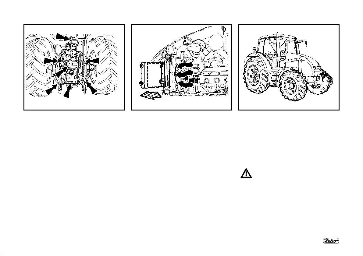
AFTER WIRK WITH FRONT
IMPLEMENTS AND IN CASE OF
COOLER CLOGGING
After work with front implements:
− Check the connections of the external
hydraulic circuit of the control of the
front three-point hitch for leaks
Clogging of the coolers:
− Remove the side plate of the hood.
− Release and slide the cooler to the left
side of the tractor.
− Clean the front walls of the engine
(gearbox, air-conditioning condenser)
cooler with compressed air (blow air in
the direction from the engine).
− Remove residual dirt from the space
under the hood so that it should not be
suctioned again.
17
TYRES AND WHEELS
Check the air pressure in the front and
rear tyres. Depending on the character
of work adjust the pressure to the
recommended value. Check and if
necessary retighten the bolts of the front
and rear wheels (the rim / disc and disc /
wheel shaft connection).
Never drive with loose wheel
bolts!
PREVENTIVE DAILY MAINTENANCE
F_02_102a
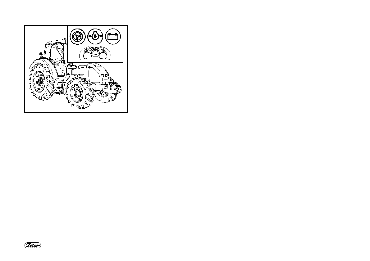
SHORT FUNCTIONAL TEST
After starting the engine check whether
the hydrostatic steering failure, engine
lubrication and charging indicators have
gone off.
Verify the function of the hydraulic
steering circuits and check them for
leaks.
18

The tractor user is obliged to get
acquainted with the recommended procedures and instructions for safe operation of the
tractor in advance. It is too late to
do so during operation!
ACQUAINTANCE WITH THE TRACTOR
Safety cab ................................................................................................................. 21
Door opening from the outside .................................................................................. 21
Door opening from the inside .................................................................................... 21
Rear window..............................................................................................................22
Side window .............................................................................................................. 22
∗Tilting lid .................................................................................................................. 22
Washer nozzle ..........................................................................................................23
Washer tank.............................................................................................................. 23
Washer control .......................................................................................................... 23
Passenger’s seat....................................................................................................... 24
Storage compartment and tool box ...........................................................................24
Rearview mirrors ....................................................................................................... 24
MARS SVRATKA driver’s seat.................................................................................. 25
Adjusting the seat for the driver’s weight................................................................... 25
Longitudinal adjustment of the seat........................................................................... 25
Vertical adjustment of the seat .................................................................................. 25
GRAMMER MAXIMO driver’s seat............................................................................ 26
GRAMMER S driver’s seat........................................................................................ 26
*Air filter with active carbon....................................................................................... 27
Control panel of heating, *air-conditioning, *radio .....................................................28
Heating valve control (A)........................................................................................... 28
Fan control (B) ..........................................................................................................28
*Air-conditioning switch (C) ....................................................................................... 28
Control of air circulation in the cab (D)......................................................................... 29
Proper function of the heating and air-conditioning system ........................................... 29
Fast heating of the cab space .....................................................................................29
Quick cooling of the cab space ............................................................................ 30
Heating or air-conditioning operation during work of the tractor ................................ 30
Immediately after cooling down the cab .................................................................... 30
Heating and air-conditioning outlets (A) (∗radio speakers)........................................ 31
Front windshield (B) defrosting.................................................................................. 31
Analog dashboard ..................................................................................................... 33
19
Page

ACQUAINTANCE WITH THE TRACTOR
Page
∗Digital dashboard .................................................................................................... 35
Selectors, switches and levers.................................................................................. 36
Light switch (A) ......................................................................................................... 37
Switch of the front driving axle (F)............................................................................. 37
Warning light switch (E) ............................................................................................ 37
Selector of the grill and cab headlights (B)................................................................ 38
Front, rear differential lock button (J) ........................................................................ 38
Selector of turn signal, low and high beam lights and horn (L).................................. 38
Switching box............................................................................................................ 39
Key in “0” position ..................................................................................................... 39
Key in “I” position ...................................................................................................... 39
Key in “II” position ..................................................................................................... 40
Lighter and three-pin socket...................................................................................... 40
Manual throttle lever ................................................................................................. 40
Engine stopping control............................................................................................. 41
Torque multiplier preselection switch (i).................................................................... 41
Pedals and levers ..................................................................................................... 42
Main shifting lever and reversing lever...................................................................... 42
Shifting lever of road and reduced gears .................................................................. 42
Shifting lever of dependent and independent PTO rpm ............................................ 43
Levers of the parking brake and hitch for a single-axle trailer ................................... 43
Hydraulic control panel.............................................................................................. 43
Control of the auxiliary hydraulic distributor (external hydraulic circuit) .......................... 44
Control panel on the right cab pillar........................................................................... 44
Battery disconnector ................................................................................................. 44
Fuel tank ................................................................................................................... 45
Drain plug of the fuel tank ......................................................................................... 45
20
ACQUAINTANCE WITH THE TRACTOR
F_02_8 F_02_11 F23
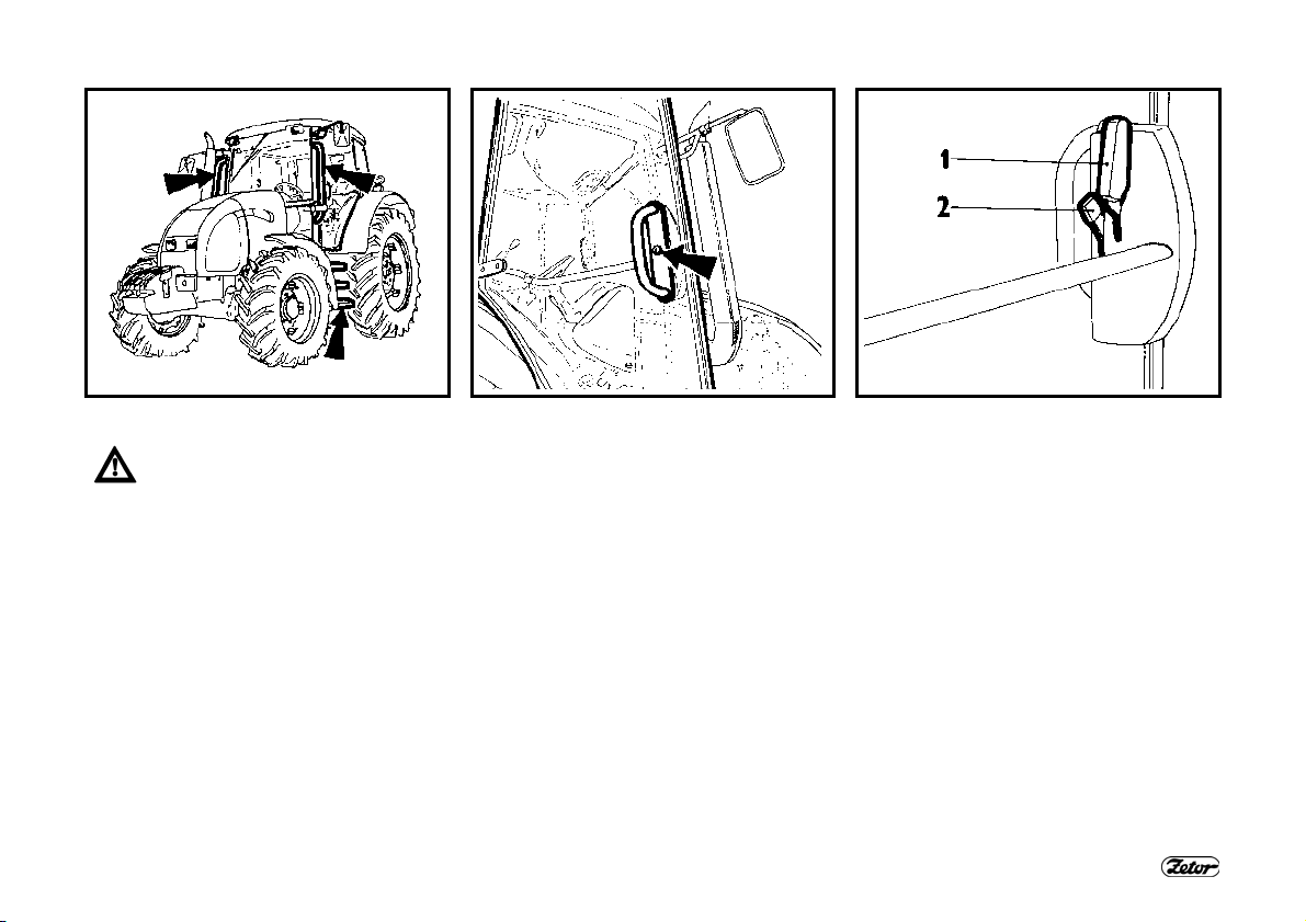
SAFETY CAB
Normally use the left side of the
tractor to enter and leave the cab.
When entering and leaving the
cab use the three-stage steps
and handles.
Pay increased attention in the
area of the shifting lever and the
manual throttle lever.
The safety cabin is equipped with tinted
glass as standard.
DOOR OPENING FROM THE OUTSIDE
The cab doors can be locked from the
outside.
DOOR OPENING FROM THE INSIDE
1. Lever for door opening from the inside
2. Lever for lock opening from the inside
The door is held in the fully open position
by a gas strut.
Driving with an open door is not recommended as the door may get damaged.
21
ACQUAINTANCE WITH THE TRACTOR
F24 F25 F_02_14
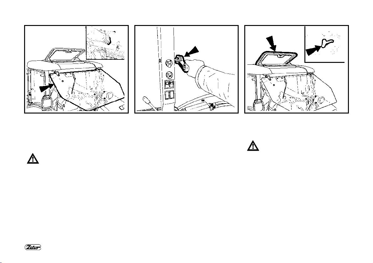
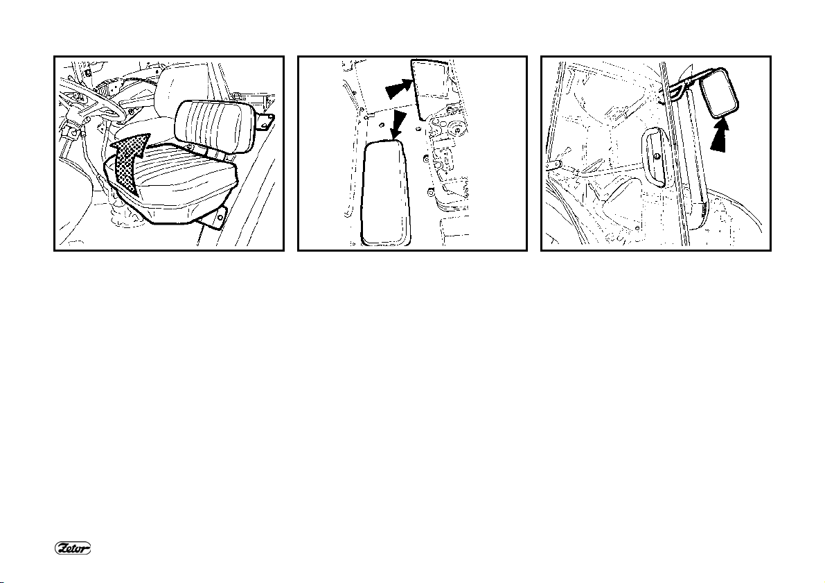
REAR WINDOW
The rear window is equipped with a handle and in the open position it is held by
gas struts. The rear window may be *
heated.
We recommend you to latch the
window in the closed position
when driving on an uneven
ground - danger of cracking of the window. Before you start work with implements attached to the rear three-point
hitch make sure there is no danger of
collision between the attached implement
in the position of maximum lift of the
three-point hitch and the open rear window. In case of interference we recommend you to work with the window
closed.
SIDE WINDOW
The window is secured in the partly open
position with a plastic latch.
∗TILTING LID
It can be opened by partial turning of the
locking lever and half-opening.
By opening the tilting lid you will
increase the total height of the
tractor. Therefore, always close
the lid when passing through or
parking in places with a lowered
profile.
22

ACQUAINTANCE WITH THE TRACTOR
F28 F_02_152a F_02_137
WASHER NOZZLE
The nozzle is adjustable with a needle
with the max. thickness of 0.8 mm.
WASHER TANK
The washer tank is located on the outer
rear wall of the cab.
WASHER CONTROL
The windshield washer is activated by
pressing of the selector of the front twospeed wiper located on the right pillar of
the cab. The maximum period of uninterrupted operation of the washer pump is
20 s.
23
ACQUAINTANCE WITH THE TRACTOR
F_02_13 F31 F_02_12
PASSENGER’S SEAT
Passenger’s seat is tilting and is situated
on the left cab fender.
Note: To facilitate access to the driver's
seat you can tilt the passenger’s seat
upwards.
STORAGE COMPARTMENT AND
TOOL BOX
The storage compartment is located at
the left side of the driver’s seat.
The toolbox is positioned in the rear part
of the cab behind the driver’s seat.
REARVIEW MIRRORS
Before driving or starting work adjust the
rearview mirrors to be able to see the entire road or the working field.
The rearview mirrors may be * heated.
24
ACQUAINTANCE WITH THE TRACTOR
F33 F34 F35
MARS SVRATKA DRIVER’S SEAT
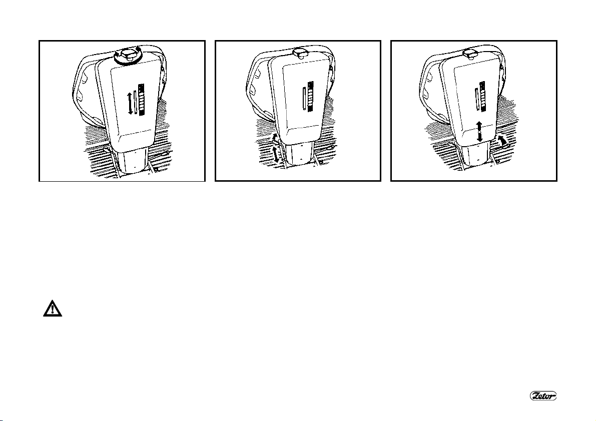
ADJUSTING THE SEAT FOR THE
DRIVER’S WEIGHT
The seat suspension is adjustable for the
driver’s weight from 50 to 120 kg. The
adjustment is performed by turning a
square handle. The weight adjustment
indicator is located in the recess of the
rear seat cover. The spring stroke is 120
mm.
Do not adjust the seat when driv-
ing. Danger of accident!
LONGITUDINAL ADJUSTMENT OF
THE SEAT
You can adjust the seat longitudinally
with the left lever in the range of ± 75
mm (11 positions).
25
VERTICAL ADJUSTMENT OF THE
SEAT
The seat is adjusted vertically with the
lever at the right-hand side in the range
of ± 30 mm (3 positions).
ACQUAINTANCE WITH THE TRACTOR
D104 F205
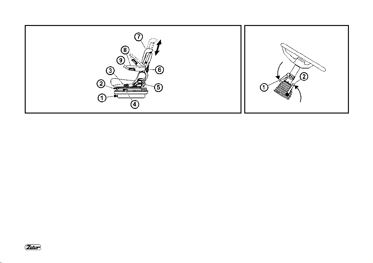
GRAMMER MAXIMO DRIVER’S SEAT
1- Seat suspension adjustment control by the driver’s weight (adjustment by turning,
direction in accordance with the pictogram on the seat bellows).
2- Longitudinal adjustment lever of the seat (located at the right side of the seat)
3- Seat turning control (the seat can be turned by 20° to both the sides)
4- Seat vibration absorption control (by flipping the control to the front you will select
the floating position of the seat)
5- Backrest angle adjustment control
6- Backrest shape adjustment control
7- Height-adjustable backrest (by pulling or pushing in the arrow direction you can
adjust it in the range of 170 mm)
8- Tilting armrest
9- Armrest adjustment control (by turning the control you can adjust the height of the
armrest)
GRAMMER S DRIVER’S SEAT
It only uses positions 1, 2 and 5.
26
ADJUSTABLE STEERING WHEEL
The tilting steering column allows variable angle and height adjustment of the
steering wheel.
Steering wheel height adjustment
The adjustment is done by extending or
retracting the steering wheel after releasing the lock by turning the lever (1) in the
arrow direction. After setting the steering
wheel lock the lever (1) by tightening
against the arrow direction.
Steering wheel angle adjustment
The adjustment is done by tilting the
steering wheel after releasing the lock by
turning the lever (2) in the arrow direction. After setting the steering wheel lock
the lever (2) by tightening against the arrow direction.
ACQUAINTANCE WITH THE TRACTOR
E730a
*AIR FILTER WITH ACTIVE CARBON
Filters with active carbon are installed instead of the standard dust filter and they are
replaced in the same way as the normal filters. The filter must be inserted with the
white side towards the grill. You will find the installation instructions in the “Maintenance instructions” chapter.
The filter is only used during spraying of pesticides; then it must be replaced with a
paper filter again as flying dust would clog the carbon filter in a very short time.
During its use the recirculation control must be in the position of “air suctioned from
the outside”
The fan control must be in the “maximum” position.
• WARNING: The filter does not provide complete protection from toxic substances
• When handling the filter wear protective gloves
• Do not clean or blow the filter with compressed air.
DANGER: Replace the active carbon filter every 200 hours or 36 months (the
production date is printed on the filter). If you feel the smell of pesticides in the
cab, replace the filter immediately and have the cab sealing checked. Used filters must be disposed of in specialized collection centres.
27
When pesticides are sprayed and
a heating filter with active carbon
is used, the recirculation control
must be in the “air suctioned from
the outside” position and the fan
control in the “maximum” position
to create overpressure in the cab.
ACQUAINTANCE WITH THE TRACTOR
F_02_15 F_02_16 F_02_17a
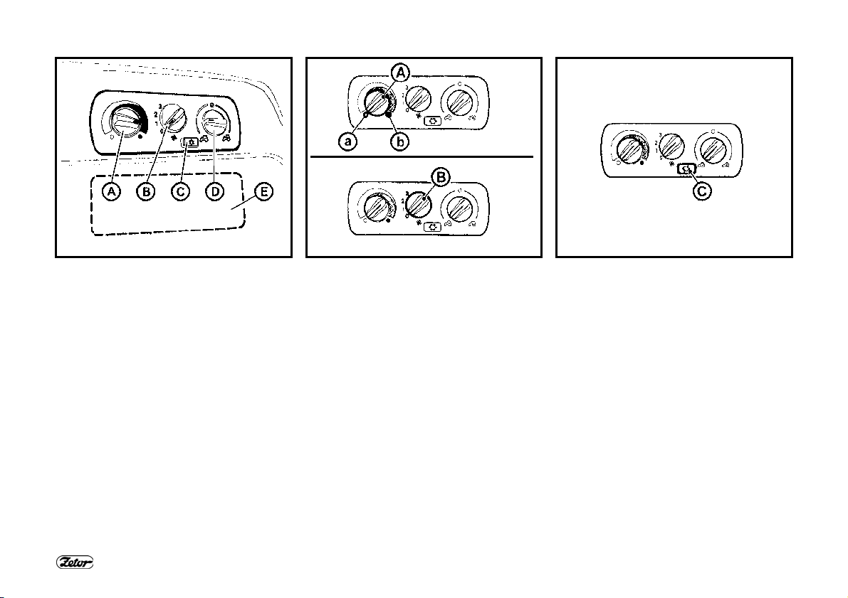
CONTROL PANEL OF HEATING, *AIRCONDITIONING, *RADIO
A - Heating valve control
B - Fan control
C - Air-conditioning switch
D - Control of air circulation in the cab
E - Space for additional radio installation
HEATING VALVE CONTROL (A)
a - Heating valve closed
b - Heating valve open
FAN CONTROL (B)
0 - Fan off
1 - Slow fan speed
2 - Medium fan speed
3 - Maximum fan speed
28
*AIR-CONDITIONING SWITCH (C)
The air-conditioning system is switched
on and off with the switch with the snowflake symbol (C).
By pressing the switch you will put the
air-conditioning system in operation (the
snowflake symbol is lit).
You can switch off the air-conditioning
system by pressing the switch again (the
snowflake symbol is off).
ACQUAINTANCE WITH THE TRACTOR
F_02_17b F_02_52 F_02_18a
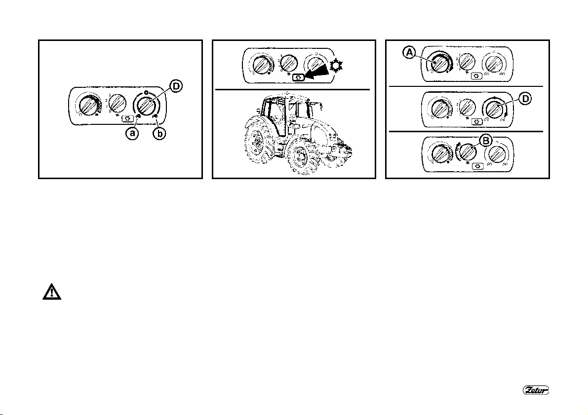
CONTROL OF AIR CIRCULATION IN
THE CAB (D)
a - Surrounding (external) air is suctioned
to the cab via filters - air suctioning
from the cab is closed.
b - Air is suctioned from the inside of the
cab and blown into the cab again (air
recirculation fast quick adjustment of
temperature in the cab).
In this position the air inlet from
the outside of the cabin is completely closed and in the cabin
there is no overpressure that prevents penetration of unfiltered air
to the cabin!
Do not use this position of the
control during working operation
of the tractor!
PROPER FUNCTION OF THE HEATING
AND AIR-CONDITIONING SYSTEM
To ensure proper functioning of the heating or air-conditioning system it is necessary to create overpressure in the cab.
Therefore, we recommend you to close
all the windows, doors and tilting lid of
the cabin.
FAST HEATING OF THE CAB SPACE
Proceed as follows:
1 - Turn the heating valve control (A) to
the right position (heating valve fully
open).
2 - Set the control of air circulation in the
cab (D) to the internal circulation position.
3 - Use the fan control (B) to select the
corresponding fan speed (position 1,
2, 3)
4 - Set the outlets to the required angle to
avoid direct blowing of air to the persons in the cab.
5 - After heating of the cab space set the
control of air circulation in the cab (D)
to the position of suctioning external
air - see fig. F_02_17b, position (a).
29
ACQUAINTANCE WITH THE TRACTOR
F_02_18 F_02_19 F_02_20
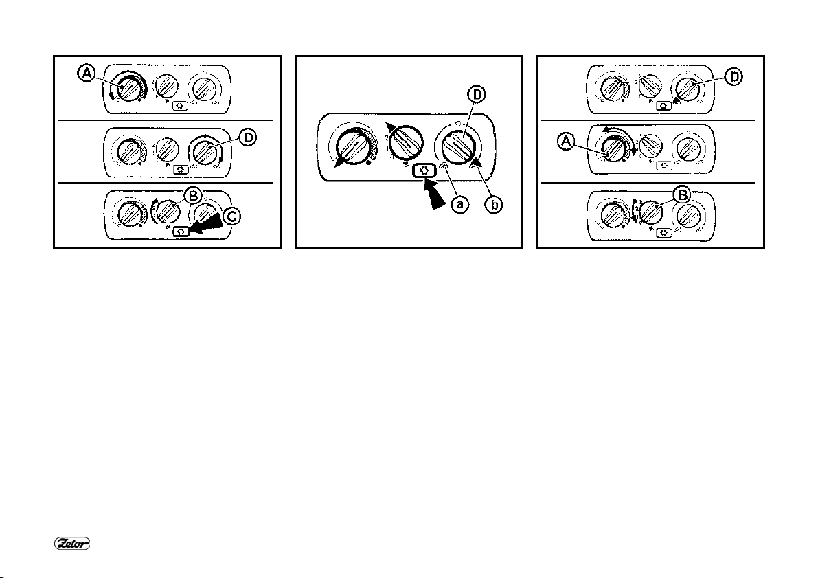
QUICK COOLING OF THE CAB
SPACE
Proceed as follows:
6 - Turn the heating valve control (A) to
the left position.
7 - Set the control of air circulation in the
cab (D) to the position of suctioning
external air.
8 - Use the fan control (B) to select the
corresponding fan speed (position 1,
2, 3)
9 - Use the switch (C) to switch on the air-
conditioning system.
10 - Set the outlets to the required angle
to avoid blowing of air directly to the
persons in the cabin (possible occurrence of an illness due to intensive
cooling of body parts).
HEATING OR AIR-CONDITIONING
OPERATION DURING WORK OF THE
TRACTOR
When internal air circulation is on, the
fresh air inlet is closed and the air in the
cab space may be breathed up by the
operators. This situation may cause the
feeling of tiredness and further due to
overpressure loss in the cab dust may
penetrate to the cab.
Note: During work set the switch (D) in
accordance with individual requirements
to a temperature in a position between
(a) and (b) so that the fan can suction air
from the outside via filters.
IMMEDIATELY AFTER COOLING
DOWN THE CAB
Immediately after cooling of the cab and
reduction of the internal temperature to
the required value we recommend you
to:
− Perform smooth regulation of air temperature with the air-conditioning on by
partially opening the heating valve (A).
At this setting the air entering the cabin
from the outlets is not dried so intensively.
− You can also smoothly regulate the air
temperature with the air-conditioning
on by reducing the fan output by
switching the control (B) to position 1
or 2.
30
ACQUAINTANCE WITH THE TRACTOR
F_02_151
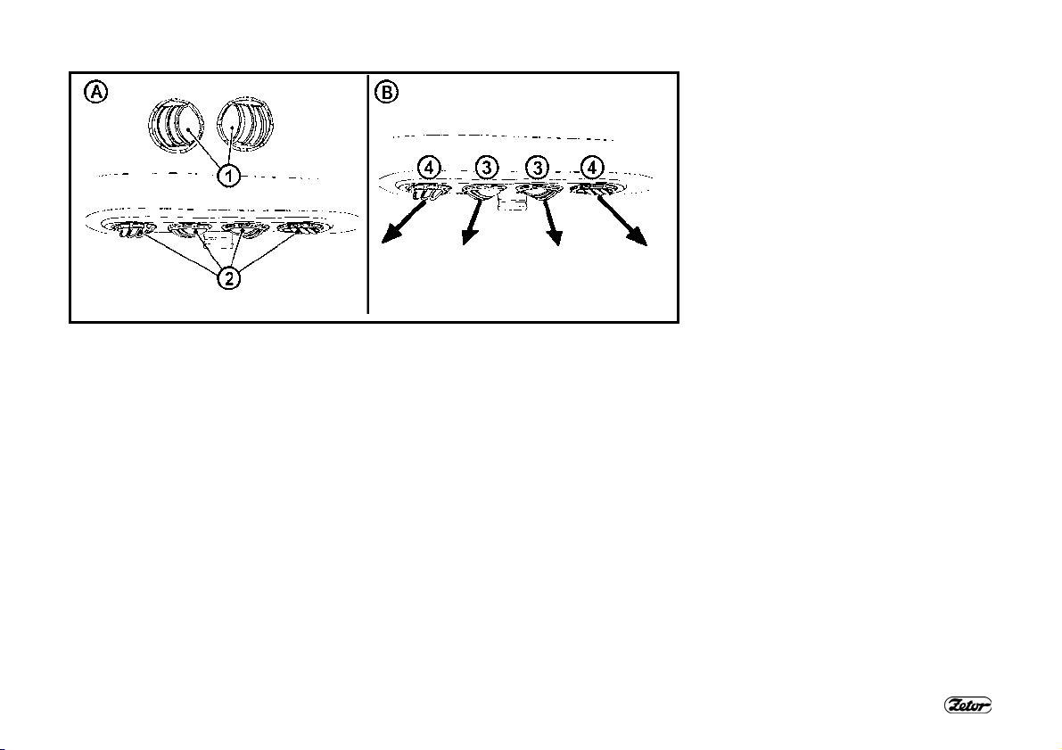
HEATING AND AIR-CONDITIONING OUTLETS (A) (∗RADIO SPEAKERS)
Adjustable outlets of heating (2) and *air-conditioning (1)
Radio speakers are only installed in case of preparation for the *radio installation.
FRONT WINDSHIELD (B) DEFROSTING
To ensure quick defrosting of the front windshield direct the central heating outlets (3)
under the angle of approx. 45° towards the windshield. Direct the side outlets (4) under the angle of approx. 45° to the cab corners.
After defrosting of the front windshield direct the side outlets to the side glasses of the
doors as necessary and gradually defrost them. After defrosting direct the outlets in
such a way that the air should not be blown directly to the driver, but down to the
driver’s legs.
31

ACQUAINTANCE WITH THE TRACTOR
B21a
32

ACQUAINTANCE WITH THE TRACTOR
ANALOG DASHBOARD
The analog dashboard is installed as
standard equipment.
DESCRIPTION OF INSTRUMENTS
A - Indicators
B - Air pressure meter
C - Engine revolution meter with a
counter of operation hours
D - Fuel gauge
E - Coolant thermometer
INDICATORS
11 - High beam lights (blue). Lights up
when high beam headlights are on.
12 - Tractor turn signal indicator (green)
st
13 - 1
trailer turn signal indicator (green)
nd
14 - 2
trailer turn signal indicator (green)
15 - Indicator of minimum air pressure in
the brake system (red). Lights up if
the air pressure for the air brakes of
the trailer drops below the critical
limit, i.e. 450 kPa.
16 - Parking brake (red). Lights up when
the parking brake lever is engaged.
17 - Charging (red). During engine opera-
tion it lights up in case of a charging
failure. If the engine is at standstill, it
must be lit
18 - Lubrication (red). During engine op-
eration it lights up if the engine oil
pressure drops below 120 to 60 kPa.
If the engine is at standstill, it must be
lit
19 - Air cleaner clogging (yellow). It lights
up if the air filter is clogged.
20 - Indicator of warning lights (red)
21 - The indicator of a critical temperature
of the coolant (red) lights up when the
temperature of approx. 100°C is
achieved (not connected).
22 - Multiplier on indicator (green - 1
stage)
23 - Multiplier on indicator (green - 2
st
nd
stage)
33
24 - Indicator of a failure in the hydro-
static steering system (red). During
engine operation it lights up in case
of a hydrostatic steering failure. If the
engine is at standstill, it must be lit
25 - Fuel (orange) Lights up when the
remaining quantity of fuel in the tank
amounts to 1/6 - 1/10 of the tank vol-
ume.
26 - PTO on indicator
27 - The indicator informs about wear of
plates of the cardan brake of the front
driving axle (red)
28 - Engine glowing (yellow) Indicates ac-
tivation of the engine start facilitation
device.
29 - Reserve
30 - Warning indicator (red) It lights up if
the air pressure drops below the criti-
cal limit, i.e. 450 kPa or when the
parking brake lever is engaged.

ACQUAINTANCE WITH THE TRACTOR
F54b
34

ACQUAINTANCE WITH THE TRACTOR
∗DIGITAL DASHBOARD
The digital dashboard is installed as optional equipment on the customer’s request.
DESCRIPTION OF INSTRUMENTS
F - Indicators
G - Air pressure meter
H - Engine revolution meter
I - Fuel gauge
J - Coolant thermometer
K - Display
INDICATORS AND BUTTONS
The arrangement of indicators on the
digital dashboard is the same as on the
analog dashboard.
After pressing of the selected button the
corresponding symbol and value will appear on the display.
31 - Button of the operation hour counter.
The value will appear on the display.
32 - Battery voltage button: The voltage
value is displayed on the display
(with the resolution of 0.1 V).
33 - Button of the number of covered
kilometres (per day or since the last
reset). The number of kilometres is
shown on the display. The value can
be reset with long pressing of the
button.
34 - Button of the current travelling speed
in km/h, which is shown on the display.
35 - 1000 rpm PTO button. The rpm
value with the resolution of 10 rpm is
shown on the display.
36 - 540 rpm PTO button. The rpm value
with the resolution of 10 rpm is
shown on the display.
35

ACQUAINTANCE WITH THE TRACTOR
SELECTORS, SWITCHES AND
LEVERS
a - Light switch (off, parking, main head-
lights)
b - Selector of low beam lights in the
tractor grill and working lights on the
tractor cab.
c - Fog light switch (off - on). The func-
tion of the fog light is indicated by
the illuminated symbol on the switch.
d - Working headlight switch (off - on).
The function of the working headlight
is indicated by the illuminated sym-
bol on the switch.
e - Warning light switch
f - Switch of the front driving axle. En-
gaged front driving axle is indicated
by the illuminated symbol on the
switch.
g - Beacon switch (off - on).
h - Free position
i - Torque multiplier preselection switch
j - Differential lock button
k - Stopping the engine run (stopping de-
vice)
l - Selector of turn signal, low and high
beam lights and the acoustic and
light warning signal
m - Switching box
XF101
36

ACQUAINTANCE WITH THE TRACTOR
F56 F57 F58
LIGHT SWITCH (A)
a - Lights “OFF”
b - Sidelights and tail lights, registration
sign and instrument lighting “ON”
c - All the electric appliances are ON as
in position “b” In addition, low or high
beam lights are “ON” (depending on
the position of the selector of the
turn signal, lights and horn)
SWITCH OF THE FRONT DRIVING
AXLE (F)
Use the front driving axle in case
the rear wheels slip to increase
the traction of the tractor.
a - Front driving axle “OFF”
b - Front driving axle “ON”
When the tractor is stopped (the tractor
is braked, engine stopped, key of the
switching box off), the front driving axle is
“ON”.
The front driving axle is on in the basic
position (indicator lit) and it can be deactivated with the switch (indicator off).
WARNING LIGHT SWITCH (E)
a - Warning lights “OFF”
b - Warning lights “ON”
The function of the warning lights is signalled by intermittent flashing of the indicator on the dashboard.
37

ACQUAINTANCE WITH THE TRACTOR
F59 F60 F_02_181
SELECTOR OF THE GRILL AND CAB
HEADLIGHTS (B)
a - Lights in the roof “OFF”
b - Lights in the roof “ON”
This selector controls the lights in the grill
or roof of the tractor cab. Only use the
lights in the cab roof if an implement is
attached to the front three-point hitch that
covers the headlights in the grill.
Switched on lights in the cabin roof are
indicated by the illuminated symbol on
the switch.
High beam lights are only available in the
tractor grill.
FRONT, REAR DIFFERENTIAL LOCK
BUTTON (J)
a - Differential lock engaged
b - Differential lock disengaged
The differential lock is engaged by pressing of the button, which returns to the
original position after being released.
The engagement of the differential lock is
indicated by the illuminated symbol on
the switch.
The differential lock is automatically disengaged on pressing of the brake pedals.
In tractors equipped with the front driving
axle with controlled differential lock the
front differential lock is activated together
with the rear differential lock.
SELECTOR OF TURN SIGNAL, LOW
AND HIGH BEAM LIGHTS AND HORN
(L)
a - Acoustic horn - push the selector in
the axial direction
b - Low beam lights
c - Right turn signal
d - Left turn signal
e - Light warning signal
f - High beam lights
38

ACQUAINTANCE WITH THE TRACTOR
E140 S43 S44
SWITCHING BOX
The switching box is located on the
dashboard, see arrow.
KEY IN “0” POSITION
The voltage of all appliances controlled
via the key is disconnected. The key can
be removed.
KEY IN “I” POSITION
Voltage is connected to all appliances
except the starter motor. The key is in
this position during engine operation.
39

ACQUAINTANCE WITH THE TRACTOR
S45 F_02_53n E144
KEY IN “II” POSITION
In this position the starter motor and all
the electric appliances are connected
except wipers, washers, cab fan and airconditioning. After starting the key automatically returns to the “I” position.
LIGHTER AND THREE-PIN SOCKET
The lighter (1) and three-pin socket are
located on the panel of the right rear
fender.
MANUAL THROTTLE LEVER
A - Maximum delivery
B - Idle run
40

ACQUAINTANCE WITH THE TRACTOR
E145b D102
ENGINE STOPPING CONTROL
By pulling the control upwards you will
stop the engine run immediately and by
turning it in the pulled position you will
lock its position.
When the engine run has stopped, return
the control to the original position.
If the control remains pulled up,
the engine cannot be started.
TORQUE MULTIPLIER
PRESELECTION SWITCH (I)
a - Preselection switch “OFF”
b - Preselection switch “ON”
Position (b) - preselection switch “ON” is
indicated by the illuminated symbol on
the switch.
If the preselection switch (b) is “ON”, on
each pressing of the clutch pedal the
medium stage of the multiplier M is
automatically engaged - on the
dashboard one indicator with the tortoise
symbol is lit (see chapter Driving Operation / Indication of the multiplier function
of the “Operator’s Manual”)
After releasing of the clutch pedal the
multiplier can be controlled with the buttons on the shifting lever.
41
During engine starting the switch
must be in the “OFF” position (a).

ACQUAINTANCE WITH THE TRACTOR
F_02_83 F_02_21 F72
PEDALS AND LEVERS
37 - Travel clutch pedal
38 - Foot brake pedals connected with a
latch
39 - Foot throttle pedal
MAIN SHIFTING LEVER AND
REVERSING LEVER
40 - Main shifting lever with three-stage
multiplier control buttons
41 - Reversing lever
SHIFTING LEVER OF ROAD AND
REDUCED GEARS
The lever is located at the left side of the
driver’s seat.
- Road gears
H -
Neutral
N -
- Reduced gears
L -
42
ACQUAINTANCE WITH THE TRACTOR
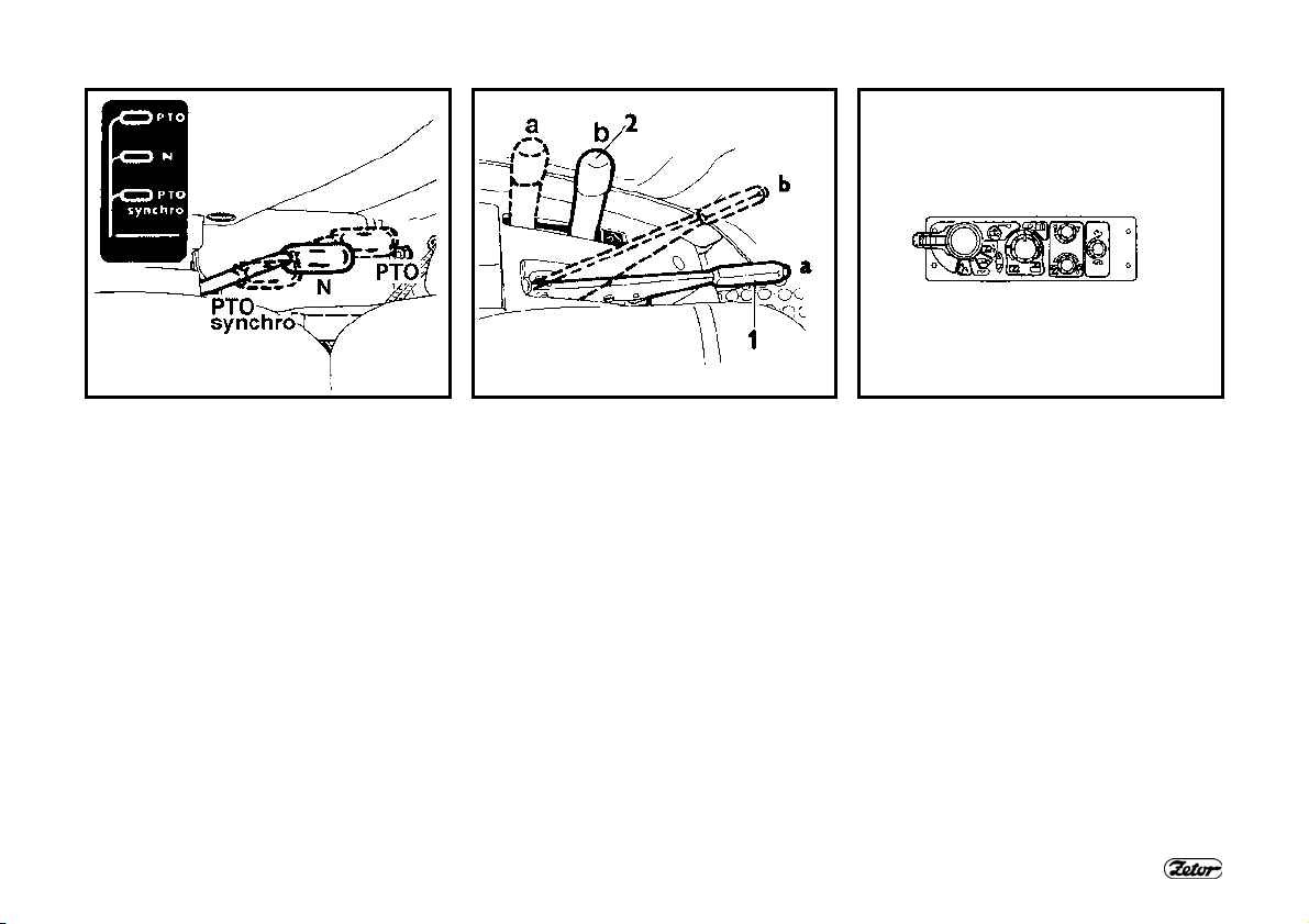
F73 F74 XF_02_213
SHIFTING LEVER OF DEPENDENT
AND INDEPENDENT PTO RPM
The lever is located at the right side of
the driver’s seat.
PTO -
N -
PTO
synchro -
Independent rpm of the
PTO engaged
Neutral position
Use this position to facilitate
the connection of the articulated shaft of an agricultural
machine.
The end piece of the rear
PTO can be rotated freely.
Dependent rpm of the PTO
engaged (the rpm value depends on the travelling
speed of the tractor)
LEVERS OF THE PARKING BRAKE
AND HITCH FOR A SINGLE-AXLE
TRAILER
42 - Parking brake lever
a - Unbraked
b - Braked
43 - Hitch control lever for a single-axle
trailer
a - Transport position
b - Carrying hooks tilted off, the pull-
ing hook with the carrier can be
lowered
HYDRAULIC CONTROL PANEL
It is located in the area of the right
fender.
Bosch electro-hydraulic system
You will find a detailed description of the
control and functions in the “Hydraulic
system” and “Electro-hydraulic system”
chapters of this Operator’s Manual.
43
ACQUAINTANCE WITH THE TRACTOR
XF_02_51 XF_02_156 F_02_175a
CONTROL OF THE AUXILIARY
HYDRAULIC DISTRIBUTOR
(EXTERNAL HYDRAULIC CIRCUIT)
It is located on the upper part of the right
fender.
You will find a detailed description of the
control and functions of the integrated
hydraulic distributor (external hydraulic
circuit) in the "Hydraulic system" chapter
of this Operator's Manual.
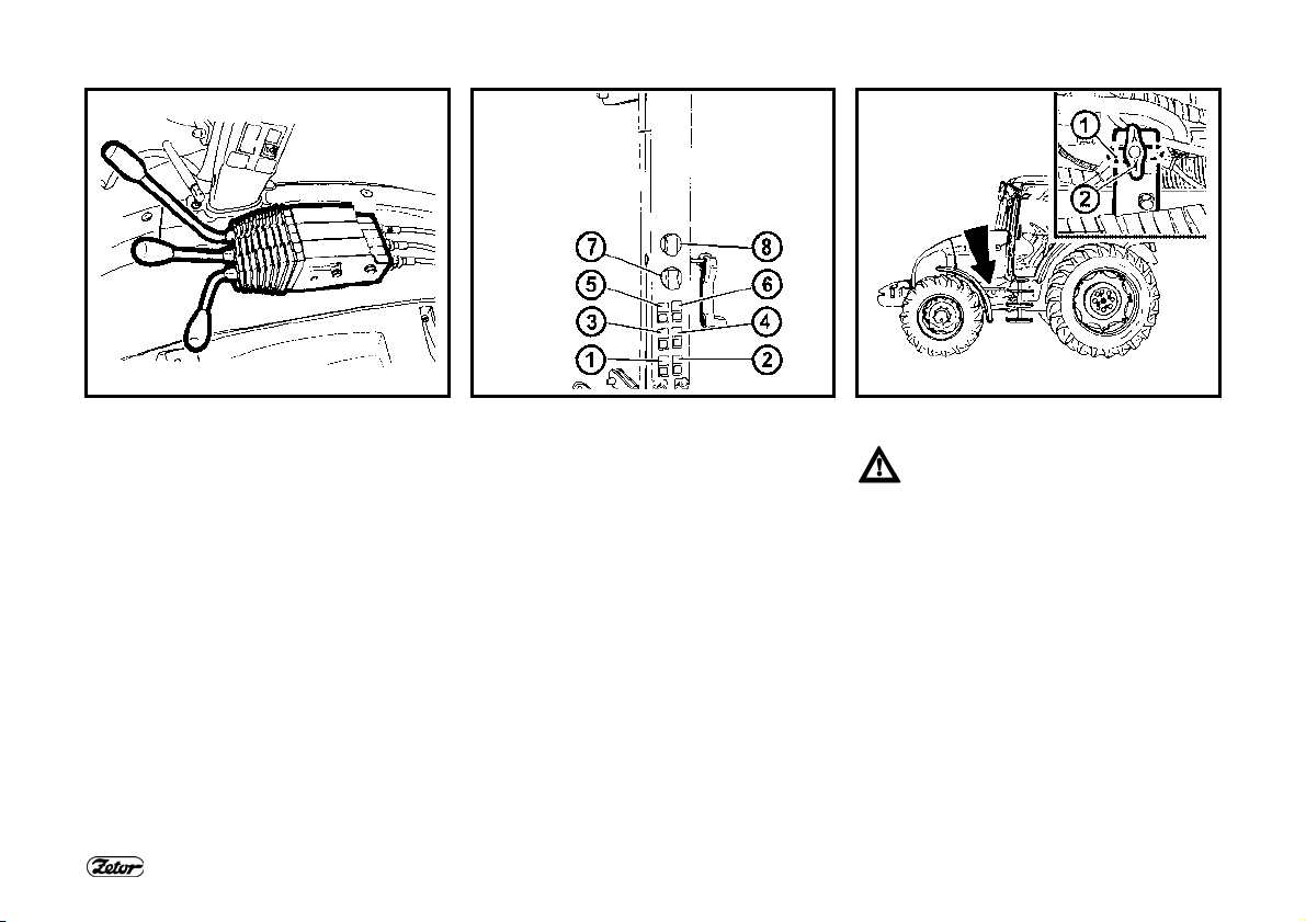
CONTROL PANEL ON THE RIGHT
CAB PILLAR
1 - ∗Front PTO switch
2 - Rear PTO switch
3 - Switch of the front working lights on
the cab roof
4 - Switch of the rear working lights on
the cab roof
5 - ∗Switch of rearview mirror heating
6 - ∗ Switch of rear window heating
7 - Rear wiper switch
8 - Two-position selector of the front
wiper and control of the front washer
44
BATTERY DISCONNECTOR
In case of long periods of inactivity, repairs, failures or an accident
immediately disconnect the battery with the battery disconnector,
which is found at the left side of
the tractor.
1 - Battery disconnected
2 - Battery connected

ACQUAINTANCE WITH THE TRACTOR
F_02_22
FUEL TANK
All the tractor types are equipped with a
plastic fuel tank with the volume of 180 l
as standard.
Do not step on the fuel tank!
DRAIN PLUG OF THE FUEL TANK
The hole for draining dirt and fuel from
the fuel tank is found in its bottom.
45
H800

NOTES
46

Before driving the new tractor first
get acquainted with the gear shifting pattern and test individual positions of the shifting lever at the
engine standstill.
Also check whether the technical
condition corresponds to traffic
safety requirements.
DRIVING OPERATION
Page
Before you start......................................................................................................... 49
If the engine will not start........................................................................................... 49
Prohibited starting methods....................................................................................... 49
Starting the tractor engine......................................................................................... 50
Indication of errors of the glowing system ................................................................. 50
∗Coolant heater......................................................................................................... 51
Starting the engine with the use of the coolant heater............................................... 51
Immediately after starting.......................................................................................... 52
Engine preheating ..................................................................................................... 52
Gear shifting.............................................................................................................. 53
Reversing lever .........................................................................................................53
Shifting of road and reduced gear speeds................................................................. 53
Shifting from lower to higher gear speed................................................................... 54
Shifting from higher to lower gear speed................................................................... 54
Three-stage torque multiplier .................................................................................... 54
Indication of the multiplier function ............................................................................ 55
Shifting the stages of the torque multiplier ................................................................ 55
Increasing, reducing the travelling speed by two gears............................................. 55
Setting in motion ....................................................................................................... 56
Driving uphill.............................................................................................................. 57
Driving downhill ......................................................................................................... 57
Foot brakes ............................................................................................................... 57
Front Cardan brake
Air brakes of trailers and semi-trailers....................................................................... 58
Warning indication of an air pressure drop................................................................ 58
Single-hose and double-hose brakes ........................................................................ 59
Single-hose brakes.................................................................................................... 59
Double-hose brakes .................................................................................................. 59
Hydraulic brakes of trailers........................................................................................ 60
Connecting and disconnecting quick-couplers of hydraulic brakes of the trailer........ 60
Front driving axle control........................................................................................... 61
Driving with the front driving axle engaged................................................................ 61
................................................................................................... 58
47

DRIVING OPERATION
Page
Ensuring free space for the Cardan shaft of the front driving axle ............................ 62
Stopping the tractor - parking brake.......................................................................... 62
Stopping the engine .................................................................................................. 62
Leaving the tractor .................................................................................................... 63
Warning indication of a hydrostatic steering error ..................................................... 63
48

BEFORE YOU START
Before you start the engine,
make sure:
1. that the tractor is properly
braked
2. that the main gear shifting lever
and the reversing lever is in
the neutral position
3. that the PTO switches on the
right cab pillar are off.
If the clutch pedal is not pressed,
the engine cannot be started - the
starting interlock switch is not actuated.
DRIVING OPERATION
F_02_28 F_02_31 F_02_32
IF THE ENGINE WILL NOT START
Return the key to position “0”. Wait for 30
seconds and repeat the start.
Never support the stopping engine with the starter motor. There
is a danger of damaging the
starter motor.
PROHIBITED STARTING METHODS
It is forbidden to start the engine
by short-circuiting the starter
motor terminals. Only start the
tractor from the driver’s seat!
During any handling or repair of
the started motor the minus pole of
the battery must be disconnected
and all the shifting levers, incl.
PTO must be moved to the neutral
position. The starter motor contacts are covered with a cap.
49

F_02_29 F_02_30 F_02_176
STARTING THE TRACTOR ENGINE
The tractors are equipped with glowing
plugs in the cylinder heads as standard.
1. Insert the key into the switching box
(position “0”).
2. Depress the clutch pedal.
3. Move the main shifting lever and the
reversing lever to the neutral position.
4. Adjust the throttle for increased fuel delivery (approx. 3/4 of the maximum
quantity).
5. Turn the key to position “I”. The yellow
indicator signalling proper function of
glowing will light up on the dashboard.
DRIVING OPERATION
6. Wait until the glowing indicator goes off
(the time depends on the temperature
of the cooling liquid).
If the glowing indicator only
flashes instead of lighting, an error has occurred in the glowing
system (chapter Indication of errors of the glowing system). Have
the reported error repaired in a
specialized repair shop.
7. Turn the key to position “II” (start).
8. Release the key immediately after starting the engine. Do not start the engine
for more than 15 s.
9. After starting the engine gradually reduce the fuel delivery. Thus, you will
prevent unnecessary operation of the
engine at high engine speed.
50
INDICATION OF ERRORS OF THE
GLOWING SYSTEM
An error of the glowing system is indicated by flashing of the glowing indicator.
- If at engine standstill the glowing indicator flashes once a second, the glowing
will occur in the emergency mode as at
low temperatures regardless of the
coolant temperature.
- If at engine standstill the glowing indicator flashes twice a second, the glowing
is off (out of operation).
- If the glowing indicator flashes permanently during engine operation, the
glowing controller is faulty and the
glowing has not been finished. This
failure must be removed immediately
as the battery might get discharged.

DRIVING OPERATION
XF_02_185a F91
∗COOLANT HEATER
The coolant heater is installed on the engine block.
The output of the heater is 1000 W at the
220 VAC supply voltage.
STARTING THE ENGINE WITH THE USE OF THE COOLANT HEATER
Heating the coolant facilitates engine starting at low ambient temperatures. The electric installation of the power supply and its protection against electric shock must
comply with valid regulations.
1. First, insert the connector to the heater.
2. Then, connect the heater to electric mains with the voltage of 220 V.
With regard to reduced wear of the engine during starting at low temperatures, the
use of the heater is recommended by the manufacturer. The heating time depends on
the ambient temperature (1 - 2 hours before the planned start should be sufficient).
After the end of heating first disconnect the device from the electric mains and
only then remove the connector from the heater!
Electric shock hazard!
It is necessary to ensure instructing of the tractor operator and regular
inspections of the coolant heater, incl. the power supply cable in the
sense of valid standards of the state where the tractor is operated, at
least before every winter.
51

DRIVING OPERATION
F_02_33a F_02_35
IMMEDIATELY AFTER STARTING
After starting set the engine
speed to 800 - 1000 rpm and let
the engine run without loading for
approx. 2 minutes.
During this time check the lubrication,
charging, hydrostatic steering (the indicators must go off) and other functions ensuring proper operation of the engine.
The period of running the engine without
loading must be observed, especially in
winter.
ENGINE PREHEATING
Continue preheating the engine while driving. Preheating the engine by
means of a long idle run or abrupt increasing of the engine speed is harmful
for the engine.
Until the coolant temperature reaches 45°C, do not exceed the engine speed
of 2000 rpm.
52

F_02_34 F_02_43 F96
GEAR SHIFTING
The tractors are equipped with a fourspeed synchronized gearbox, threestage torque multipliers and two-speed
reduction.
The four-speed gearbox is controlled
with the main shifting lever with control
buttons of the torque multiplier (1). The
forward and reverse motion of the tractor
is selected with the reversing lever (2).
The gearbox does not make it
possible to use the fourth speed
for the reverse motion.
DRIVING OPERATION
REVERSING LEVER
The reversing lever is used to select the
driving direction of the tractor (forward,
reverse).
Forward drive
F -
Neutral
N -
Reverse drive
R -
The reversing gearbox offers 18 reverse
speeds that are approximately as fast as
the forward speeds. Therefore, consider
well and select a suitable reverse speed
for the particular character of work.
Shift the reversing lever with the
clutch pedal depressed and the
tractor standing. To drive in the
reversing direction move the reversing lever to the R position.
SHIFTING OF ROAD AND REDUCED
GEAR SPEEDS
- Road gears
H -
Neutral
N -
- Reduced gears
L -
Shifting of gears of the main gearbox at
reduced gear speeds is the same as in
the case of road speeds
The shifting lever of road and reduced speeds can only be shifted
with the tractor at standstill.
53

F_02_44 F_02_45 F99
SHIFTING FROM LOWER TO HIGHER
GEAR SPEED
Depress the clutch pedal (clutch disengaged). At the same time release the
foot throttle pedal and shift the required
higher gear. Smoothly release the clutch
pedal (the clutch starts engaging) and at
the same time increase the engine
speed.
DRIVING OPERATION
SHIFTING FROM HIGHER TO LOWER
GEAR SPEED
Depress the clutch pedal and move the
shifting lever via the neutral position to
the lower gear.
Note: To extend the life of the syn-
chromesh you can shift the gear from
higher to lower speed using the “double
clutch depressing”.
THREE-STAGE TORQUE MULTIPLIER
The three-stage multiplier is standard
equipment of all tractor types.
Shifting of individual stages of the threestage multiplier is controlled with two buttons on the main shifting lever head.
It is performed without depressing of the
travelling clutch pedal (under load).
The entire shifting is automatic even
when the tractor is loaded.
1.00 ratio (high stage)
H -
1.16 ratio (medium stage)
M -
1.34 ratio (low stage)
L -
54
F100 F101 F102
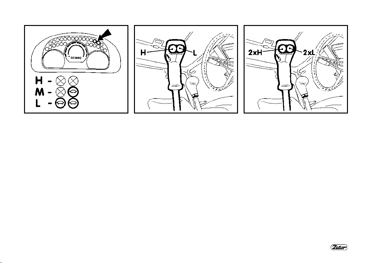
INDICATION OF THE MULTIPLIER
FUNCTION
Individual engaged stages of the multiplier (H,M,L) are signalled by indicators
on the dashboard with the tortoise symbol.
Symbols OFF
H -
One indicator with the tortoise
M -
symbol is lit.
Two indicators with the tortoise
L -
symbol are lit.
Note: On starting or stopping of the tractor engine the H stage is always engaged
automatically.
DRIVING OPERATION
SHIFTING THE STAGES OF THE
TORQUE MULTIPLIER
Increasing the travelling speed
H -
Reducing the travelling speed
L -
INCREASING, REDUCING THE
TRAVELLING SPEED BY TWO GEARS
Increases the travelling speed by
2xH
two gears
Reduces the travelling speed by
2xL
two gears
55

SETTING IN MOTION
1. Select road or reduced gears.
2. Depress the clutch pedal.
3. Shift the main shifting lever and the
reverse lever to the neutral position
and switch off the PTO switches on
the right cab pillar.
4. Start the engine
5. Set the engine speed to 800 rpm.
6. Shift the reversing lever to the requested driving direction of the tractor (forward or reverse).
7. Select the suitable gear for putting the
tractor in motion.
8. Slightly increase the engine speed.
9. Get the parking brake ready for releasing.
DRIVING OPERATION
F_02_36
10. Release the clutch pedal until the
travel engagement point and while simultaneously increasing the engine
speed continue releasing the clutch
pedal smoothly.
11. Release the parking brake completely.
12. Start moving smoothly and slowly.
Very fast acceleration may cause overloading of the power train, increased fuel
consumption, excessive wear of tyres
and damage of the transported load.
Only use the 1
motion when driving with a heavy trailer
uphill and in rough terrain.
st
gear to put the tractor in
56
When shifting individual gear
speed (1-4) or reversing (F-R)
observe the instructions for putting the tractor in motion and gear
shifting in this manual. When the
tractor has been started and is
still standing, depress the clutch
pedal and wait for approx. 2 seconds. Only then shift the required
gear speed or select the reverse
direction.
To increase safety and to avoid
unexpected situations use the
foot brake during the shifting as
well.

F_02_37 F_02_38 F106
DRIVING UPHILL
When driving uphill, shift from the
higher to the lower speed in time
to avoid the engine speed dropping below 800 rpm and avoid
such driving that would lead to
stopping of the engine due to
overloading.
DRIVING OPERATION
DRIVING DOWNHILL
Driving downhill without an engaged gear is prohibited. When
driving down a longer slope, shift
the lower gear, the steeper the
slope is. If possible, shift the
lower gear before the slope already.
Note: The gear that allows you to get
uphill reliably is also suitable for getting
down the hill safely.
FOOT BRAKES
The foot brakes are of the disc, wet, hydraulically controlled, double-pedal type
with an automatic pressure compensator.
During driving on a road both the
pedals must be connected with a
latch. Only use unlatched pedals
for braking the right or left wheel
separately during terrain work
and in the field.
Note: When driving down a steep slope
with a trailer or semi-trailer equipped with
air or hydraulic brakes you must use the
foot brake from the beginning of the
slope already.
During braking with one brake
pedal the trailer brakes are not
in operation!
57
FRONT CARDAN BRAKE
If only one brake pedal is used,
the Cardan brake is not activated.
DRIVING OPERATION
F108 F_02_39 F_02_55
AIR BRAKES OF TRAILERS AND
SEMI-TRAILERS
The control of the air brakes of trailers
(semi-trailers) and the control of the tractor brakes is designed in such a way that
the braking effect of both the vehicles is
synchronized.
The working pressure is set by the pressure controller to 740 ± 20 kPa. If the
pressure drops below 550 - 40 kPa, the
relief valve puts the secondary devices
(differential lock, engagement of the front
driving axle, etc.) out of operation.
WARNING INDICATION OF AN AIR
PRESSURE DROP
A pressure drop below 450 kPa is signalled by lighting up of the red indicator
located on the dashboard.
In case of a pressure drop below
450 kPa in the air pressure system a tractor with a braked trailer
or semi-trailer must not continue
travelling until the air pressure increases again.
58

F_02_56 F_02_57 F_02_58
SINGLE-HOSE AND DOUBLE-HOSE
BRAKES
1. Coupling of single-hose brakes
2. Couplings of double-hose brakes
After disconnection or without a
connected trailer (semi-trailer) the
couplings must be closed with a
cap.
DRIVING OPERATION
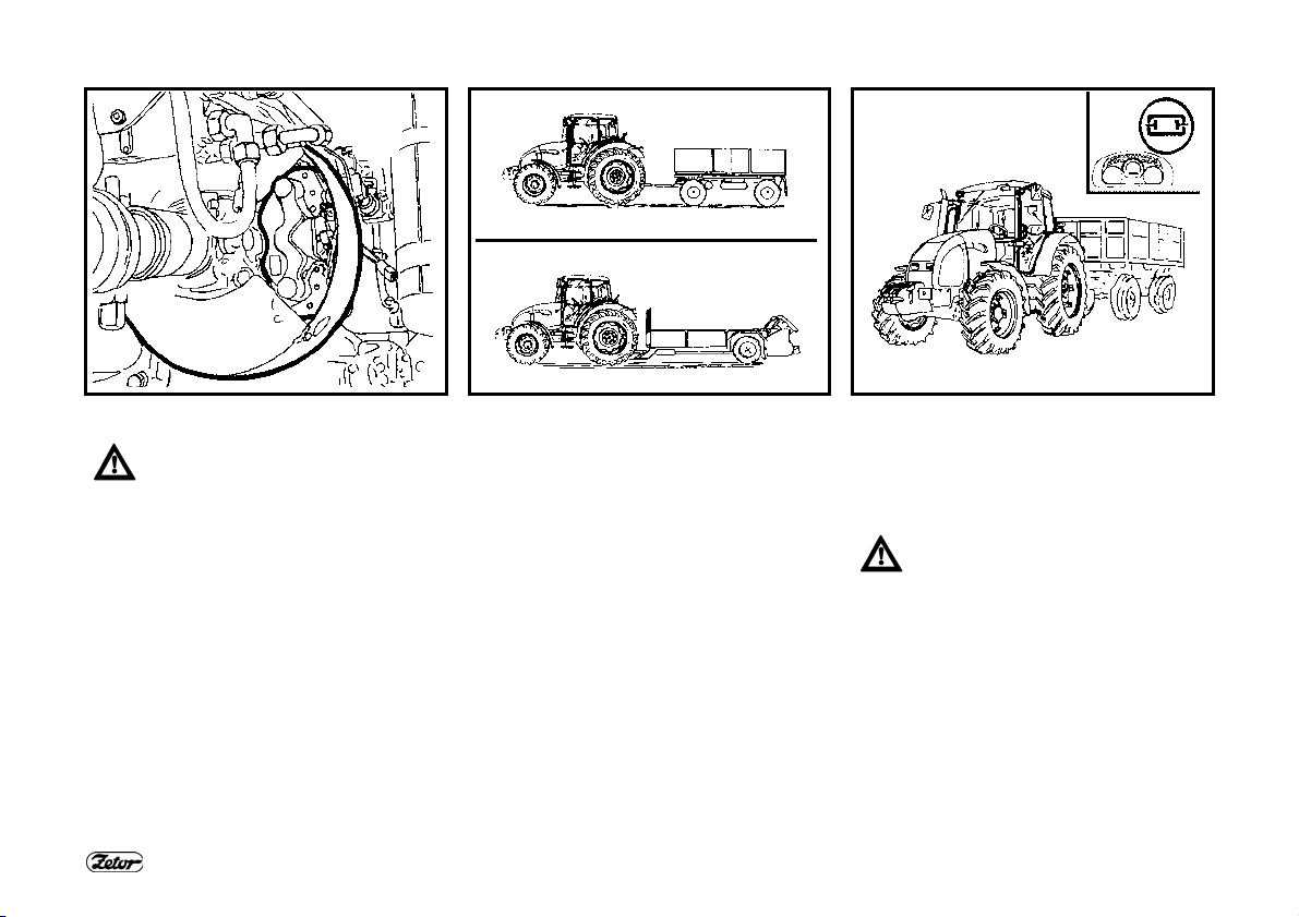
SINGLE-HOSE BRAKES
The cap is marked black.
After connection of a trailer
(semi-trailer) with the maximum
permissible speed approved for
the particular tractor type the
maximum allowed speed of the
set is 30 km/h.
The maximum permissible speed
of the set results from the maximum permissible speed of the
slower vehicle in the set.
DOUBLE-HOSE BRAKES
The cap of the left coupling is marked
yellow (braking branch) and the cap of
the right coupling is marked red (filling
branch).
After connection of a trailer
(semi-trailer) with the maximum
permissible speed approved for
the particular tractor type the
maximum allowed speed of the
set is 40 km/h.
The maximum permissible speed
of the set results from the maximum permissible speed of the
slower vehicle in the set.
59

DRIVING OPERATION
E230a
HYDRAULIC BRAKES OF TRAILERS
Connect the hydraulic brakes of a trailer or semi-trailer to the quick-coupler marked
with an arrow.
The control of the hydraulic brakes of trailers (semi-trailers) and the control of the
tractor brakes is designed in such a way that the braking effect of both the vehicles is
synchronized. The working pressure is applied by oil delivered by a permanent gear
pump of the hydraulic system.
The brake valve of the trailer is controlled by the pressure of the brake liquid from the
main brake cylinders depending on the force applied onto the brake pedal. At the
maximum depression of the brake pedal the pressure at the coupling must amount to
12 - 15 MPa. The brake valve makes sure that the brake function overrides the hydraulic function.
If during depression of the foot brake pedals shocks occur in the hydraulic circuit, it is
necessary to bleed the hose leading from the brake valve to the quick-coupling.
During driving with a hitched trailer or semi-trailer the pedals of the foot brake
must be connected and secured with a latch.
During braking with one brake pedal the hydraulic brakes of the trailer
are not in operation.
CONNECTING AND DISCONNECTING
QUICK-COUPLERS OF HYDRAULIC
BRAKES OF THE TRAILER
When connecting and disconnecting the quick-couplers pay
increased attention with regard to
the residual oil that remains in the
socket or on the plug of the
quick-coupler.
For environmental reasons after
every disconnection of quickcouplers this residual oil must be
removed with any textile material.
60

F116 H223
FRONT DRIVING AXLE CONTROL
The front driving axle is “ON” in basic
position (the indicator lights up). It can be
disengaged with the corresponding
switch on the dashboard.
a - Front driving axle “ON”
b - Front driving axle “OFF”
When the tractor is stopped (the tractor
is braked, engine stopped, key of the
switching box off), the front driving axle is
“ON”.
DRIVING OPERATION
DRIVING WITH THE FRONT DRIVING AXLE ENGAGED
Use the front driving axle in case the rear wheels slip to increase the traction
of the tractor.
On a road and hard surface driving with the front driving axle engaged is acceptable up to the maximum speed of 15 km/h (driving with the front axle engaged causes increased wear of the front tyres).
Permanent engagement of the front driving axle is permissible if an agricultural machine or implement is attached to the front of the tractor. This condition is mentioned
in the operator’s manual of the corresponding machine.
The maximum allowable speed of these sets is 15 km/h.
61
F_02_40 F_02_60 XF_02_186
ENSURING FREE SPACE FOR THE
CARDAN SHAFT OF THE FRONT
DRIVING AXLE
When installing auxiliary units or
connecting implements make
sure that around the Cardan shaft
of the front driving axle there is at
least 10mm free space all along
its length at any oscillation of the
axle.
If this principle is not observed,
there is a danger of damaging
the tractor and machine.
DRIVING OPERATION
STOPPING THE TRACTOR - PARKING
BRAKE
Under normal conditions stop the tractor
slowly. Shortly before stopping:
1. Depress the clutch pedal.
2. Shift the main gear shifting lever to the
neutral position.
3. After every stopping secure the tractor
against accidental movement with the
parking brake. Activation of the parking brake is signalled by illumination of
the corresponding indicator on the
dashboard.
STOPPING THE ENGINE
After work of the tractor when the engine
was fully loaded, the engine must be left
to cool down.
1. Before stopping the engine reduce the
engine speed to 800 - 1000 rpm and
let the engine run without loading for
approx. 5 minutes.
2. Move the manual throttle lever to the
STOP position.
3. Pull up the control of the engine stopping device and hold it in the extended position until the engine operation stops.
4. After stopping the engine you can turn
the key from position “I” to position
“0”.
62

F_02_67 F_02_68
LEAVING THE TRACTOR
You can turn the key from the “I” to the
“0” position only with the engine at
standstill - the charging indicator must be
lit.
If the tractor is standing on a slope, it
must be secured against spontaneous
movement: braked with the parking
brake, engine stopped, the reversing
lever shifted depending on the tractor inclination on the slope either in the forward or reverse position, the main shifting lever engaged in a low gear position
and the wheels secured with wedges.
Before leaving a tractor with the
safety cab remove the key from
the switching box and lock the
cab.
DRIVING OPERATION
Note: When the engine is stopped, the
front driving axle is automatically engaged.
WARNING INDICATION OF A
HYDROSTATIC STEERING ERROR
An error of the hydrostatic steering pump
is signalled in case of a pressure drop
below 120 kPa downstream of the pump
on the dashboard by the corresponding
symbol.
Note: During starting of the engine or at
low engine speed the indicator may flash
slightly; if after starting or increase of the
engine speed the indicator goes off, it is
not an error.
63

NOTES
64

RUNNING IN THE TRACTOR
General principles for running in the new tractor in the course of the
first 100 hours of operation........................................................................................ 66
During the first 10 hours............................................................................................ 66
From 100 hours on.................................................................................................... 67
Page
65

RUNNING IN THE TRACTOR
F_02_48 F_02_49
GENERAL PRINCIPLES FOR RUNNING IN THE NEW TRACTOR IN THE
COURSE OF THE FIRST 100 HOURS OF OPERATION
During the first 100 operation hours:
- Load the engine normally
- Avoid operation under partial loading of the engine
- Avoid excessive idle run
- Frequently check the oil level in the engine (increased oil consumption is normal in
this period).
- Check screw connections mainly of the supporting parts of the tractor.
- Immediately remove all established shortcomings; thus, you will prevent
subsequent damage and possible impairment of operation safety.
- Proceed in the same way after a general overhaul of the tractor as well.
66
DURING THE FIRST 10 HOURS
- Run in the tractor in the transport
regime.
- Tighten the fitting nuts of the front and
rear wheels, including the bead / rim
connections at the prescribed torque.

E256
FROM 100 HOURS ON
After running-in you can work with the
tractor without any restrictions.
Recommended
operation speed
Idle speed 800 ± 25 rpm
Operation oil
pressure
Oil pressure at the
idle speed
Max. coolant
temperature
1400 - 2300 rpm
0.2 - 0.5 MPa
min. 0.05 MPa
106°C
RUNNING IN THE TRACTOR
67

NOTES
68

Before you start, make sure that
the technical condition of the tractor corresponds to requirements
for safe operation. When a trailer
or implement is attached, check
its connection and proper fixation
of the load. Never leave the tractor while it is moving to connect
the trailer by yourself. Also take
care of your assistant’s safety.
TRANSPORTATION
Page
CBM stage quick-adjusting hitch ............................................................................... 70
Height adjustment and disassembly of the CBM stage hitch..................................... 70
Automatic mouth of the CBM stage hitch .................................................................. 70
Modular system of hitches for trailers and semi-trailers ............................................71
Swinging draw-bar console module........................................................................... 71
Swinging draw-bar..................................................................................................... 71
Swinging draw-bar console with a fixed pin module .................................................. 71
Console with a ø 80 ball module ...............................................................................72
Hitch for a single-axle CBM semi-trailer .................................................................... 72
Maximum permissible vertical static load of hitches for trailers and semi-trailers...... 73
69

D201 D202 E304
CBM STAGE QUICK-ADJUSTING
HITCH
It is designed for attachment of doubleaxle trailers or lighter single-axle semitrailers. The guiding mouth is height adjustable. During work with various implements it may be necessary to adjust
the height of the hitch or to disassemble
the entire hitch.
TRANSPORTATION
HEIGHT ADJUSTMENT AND
DISASSEMBLY OF THE CBM STAGE
HITCH
By moving the control lever in the arrow
direction to position (1) you will release
the lever and by moving it subsequently
to position (2) you will retract the locking
pins (3). Now, the stage hitch is released
and you can adjust its height or disassemble it.
When you release the lever from position
(2), the locking pins (3) will extend and
the lever will automatically return to the
initial position.
AUTOMATIC MOUTH OF THE CBM
STAGE HITCH
When the lever (1) is moved in the direction of the arrow (a), the pin (2) is retracted to the upper position, which is
signalled by the extended indicator (3),
see fig. (A).
When the mouth gets onto the shaft lug,
the pin will automatically slide into the lug
of the connected trailer. You can lower
the hitch pin (2) manually by moving the
lever (1) in the arrow (b) direction. The
insertion of the pin is signalled by the retracted indicator (3), see fig. (B).
After the attachment of the trailer
you must always check whether
the indicator (3) is retracted in
accordance with fig. (B).
70

D204 D205 D206
MODULAR SYSTEM OF HITCHES FOR
TRAILERS AND SEMI-TRAILERS
Module types:
Fig. (B) - Swinging draw-bar console
Fig. (C) - Swinging draw-bar console with
a fixed pin
Fig. (D) - Console with a ø 80 ball
Disassembly, fig. (A):
1- Remove the locking screw (1).
2- Secure the module against sinking,
release and disassemble the pins (2).
3- Slide the module out of the console
downwards.
Do the assembly in the reverse order.
TRANSPORTATION
SWINGING DRAW-BAR CONSOLE
MODULE
The swinging draw-bar console module
is located in the stage hitch console.
SWINGING DRAW-BAR
Disassembly:
1- Release and remove the pins (1).
2- Slide the swinging draw-bar out in the
arrow direction.
Do the assembly in the reverse order.
71
SWINGING DRAW-BAR CONSOLE
WITH A FIXED PIN MODULE
Perform the assembly and disassembly
of the swinging draw-bar in accordance
with the “Swinging draw-bar” chapter.
Connecting the shaft lug to the fixed pin
(3):
1- Release and remove the pin (1).
2- Lift the locking wedge (2) in the arrow
direction.
3- Connect the shaft lug to the fixed pin
(3):
4- Return the locking wedge (2) to the
original position and secure it with the
pin (1).

TRANSPORTATION
D207 D208
CONSOLE WITH A Ø 80 BALL
MODULE
The console with a ø 80 ball is
only used to connect semi-trailers
with a hitching device designed
for a ø 80 ball.
Releasing the hitch, fig. (A):
By moving the lever (1) in the arrow direction you will remove the locking
wedge (2).
Locking the hitch, fig. (B):
By moving the lever (1) in the arrow direction you will retract the locking wedge
(2).
HITCH FOR A SINGLE-AXLE CBM
SEMI-TRAILER
The hitch for a single-axle semi-trailer
may be equipped with a hook (A) or with
a swinging draw-bar (B).
Replacing the hook with the swinging
draw-bar (C):
1- Lower the hitch.
2- Release and remove the pin (1).
3- Remove the hook in the arrow direc-
tion.
Install the swinging draw-bar in the reverse order.
72

TRANSPORTATION
MAXIMUM PERMISSIBLE VERTICAL STATIC LOAD OF HITCHES FOR TRAILERS AND SEMI-TRAILERS
Hitch type Permis-
sible ver-
tical
static
load
Hitch class C
2,000 kg
Hitch
pin Ø
31 mm
Hitch type Permis-
sible ver-
tical
static
load
2,000 kg
Hitch class D2 Hitch class D3
2,000 kg
43 mm
2,000 kg
The maximum weight of an aggregated braked trailer or semi-trailer must not exceed the value specified on the data plate
of the tractor and the value specified in the technical certificate of the tractor. The maximum permissible speed of the set
results from the maximum permissible speed of the slower vehicle in the set.
Hitch of class C: max. weight of the trailer 6,000kg.
Hitch of class D2: max. weight of the trailer 14,000kg.
Hitch of class D3: max. weight of the trailer 20,000kg.
Hitch
pin Ø
38 mm
50 mm
Hitch type Permis-
sible ver-
tical
static
load
2,000 kg
Hitch
pin Ø
28 mm
73

TRANSPORTATION
MAXIMUM PERMISSIBLE VERTICAL STATIC LOAD OF HITCHES FOR TRAILERS AND SEMI-TRAILERS
Hitch pin
(ball) Ø
80 mm
31 mm
Hitch type
Permissible
vertical
static load
2,000 kg
Hitch type Permissible
vertical
static load
736 kg
Hitch pin
(ball) Ø
31 mm
3,000 kg
47 mm
1,200 kg
Hitch type
Permissible
vertical
static load
Fixed pin
2,000 kg
Hitch pin
(ball) Ø
44.5 mm
The maximum weight of an aggregated braked trailer or semi-trailer must not exceed the value specified on the data plate
of the tractor and the value specified in the technical certificate of the traktor. The maximum permissible speed of the set
results from the maximum permissible speed of the slower vehicle in the set.
74

Before connecting a machine
driven by a PTO of the tractor
check whether the speed of the
PTO of the machine corresponds
to the speed of the tractor PTO
(540 rpm or 1000 rpm). Different
speeds may lead to serious
damages and injuries.
DRIVE OF AGRICULTURAL MACHINES
Working with PTO ..................................................................................................... 76
Control of the front and rear PTO.............................................................................. 77
Rear PTO - selection of dependent and independent speed (rpm) ........................... 77
Changing the independent speed value of the rear PTO .......................................... 78
PTO end pieces ........................................................................................................ 78
Front PTO - Zuidberg ................................................................................................ 78
Drive of machines with larger inertial masses ........................................................... 79
Page
75

DRIVE OF AGRICULTURAL MACHINES
F146
WORKING WITH PTO
1. When working with the PTO make sure that all the covers are properly
attached.
2. After the end of the work always reassemble the PTO guard.
3. Always connect and disconnect the articulated shaft of the attached
machine to and from the tractor with the lever of dependent and
independent rpm of the PTO shifted to the N - Neutral position.
4. Any repairs or cleaning of parts of attached machines driven by the PTO
may only be carried out with the engine stopped, PTO clutch disengaged
and the lever of the dependent and independent PTO rpm shifted to the N Neutral position.
76

DRIVE OF AGRICULTURAL MACHINES
F_02_179 F73
CONTROL OF THE FRONT AND REAR PTO
The clutches of the PTO’s are switched on (at the min. engine speed of 1500 rpm)
and off electro-hydraulically.
The switching is performed with the use of switches located on the right cab pillar.
The switches are equipped with mechanical locks (1) against accidental activation.
When using a switch, press the lock downwards.
The switch controls the
P -
electromagnetic valve of the front
PTO
The switch controls the valve of
Z -
the rear PTO
By pressing both the switches you will activate both the PTO’s (front and rear).
Activation of the PTO’s is indicated by the illuminated symbol on the switch.
77
REAR PTO - SELECTION OF
DEPENDENT AND INDEPENDENT
SPEED (RPM)
PTO -
N -
PTO
synchro -
Independent rpm of the
PTO engaged
Neutral position
Use this position to facilitate
the connection of the
articulated shaft of an
agricultural machine.
The end piece of the rear
PTO can be rotated freely.
Dependent rpm of the PTO
engaged (the rpm value
depends on the travelling
speed of the tractor)
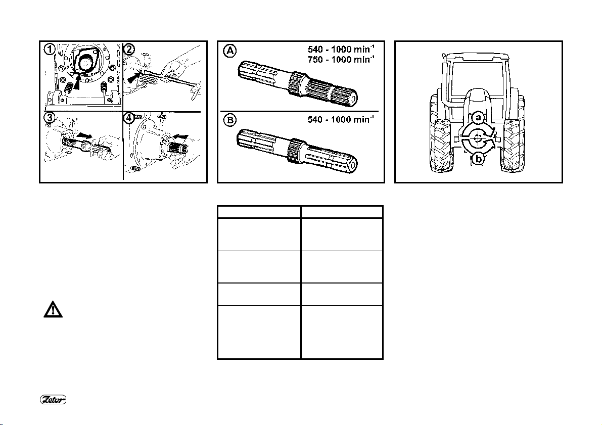
DRIVE OF AGRICULTURAL MACHINES
F149 F150 F_02_64
CHANGING THE INDEPENDENT
SPEED VALUE OF THE REAR PTO
The speed setting of the PTO is
performed by turning of the Ø 35 mm
end piece of the PTO.
1. Disassemble the PTO guard.
2. Release the shim.
3. Remove and turn the end piece.
4. Insert the end piece with the opposite
end first and secure the shim.
Check whether you have set the
proper speed with regard to the
attached implement.
You can only change the 540 and
1000 rpm PTO speed (or 750
and 1000 rpm) with the PTO
stopped.
PTO END PIECES
Speed (rpm) End piece
540 and 1000 rpm
standard (A)
540 - 1000
standard (B).
∗750 and 1000
option (A)
∗1000
option
540 - 6 splines
1000 - 21 splines
standard
540 - 6 splines
1000 - 6 splines
750 - 6 splines
1000 - 21 splines
It is not possible
to change the rpm
value - the end
piece is not
replaceable
78
option
FRONT PTO - ZUIDBERG
The front PTO is equipped with a fixed
six- or twenty-one-spline end piece and it
only has the speed of 1000 rpm.
The tractor may be optionally equipped
with the front PTO with a different turning
direction:
in accordance with the turning
a -
direction of the engine (standard)
against the turning direction of
b -
the engine (* option)

DRIVE OF AGRICULTURAL MACHINES
F_02_46
MAXIMUM TRANSMITTED POWER
PTO Transmitted
power
Front (Zuidberg)
1000 rpm 45 kW*
Rear
1000 rpm full engine power
540 rpm full engine power
540E rpm full engine power
* In case of power transmission without
impacts the value of the maximum
transmitted power can be increased to
50 kW
DRIVE OF MACHINES WITH LARGER
INERTIAL MASSES
(CRUSHERS, HARROWS, MOWING
MACHINES, ETC.)
The Cardan shaft of the drive of these
machines must be equipped with a "freewheel" device that will ensure
disconnection of the torque transmission
in case of return transmission from the
machine to the tractor
79

NOTES
80

HYDRAULIC SYSTEM
Hydraulic system....................................................................................................... 82
Hydraulic pump .........................................................................................................82
Location of control elements - EHR - B - Bosch electro-hydraulic system................. 82
Outer hydraulic circuit................................................................................................ 83
Connecting and disconnecting quick-couplers ..........................................................83
Oil quantity drawn from the outer hydraulic outlets.................................................... 84
Hydraulic distributor of the outer hydraulic circuit...................................................... 85
Description of the functions of individual positions of control levers of the hydraulic
distributor ..................................................................................................................86
Rear outlets of the outer hydraulic circuit .................................................................. 87
Front outlets of the outer hydraulic circuit.................................................................. 87
Connecting machines and implements to the outer hydraulic circuit ......................... 88
Page
81

F_02_112 F_02_113 F_02_53
HYDRAULIC SYSTEM
The system consists of the inner and
outer circuit.
The source of pressurized oil is a gear
pump.
Oil is drawn from the common filling of
the gearbox and final drive housing.
HYDRAULIC SYSTEM
HYDRAULIC PUMP
The hydraulic pump cannot be disengaged. When the engine is running, the
pump is in operation.
Pump type Delivered quantity
2. UD 25.02 V 69 l/min
The pressure generated in the hydraulic
system by the hydraulic pump is limited
by a relief valve to 20 MPa.
82
LOCATION OF CONTROL ELEMENTS
- EHR - B - BOSCH ELECTROHYDRAULIC SYSTEM
The control panel (1) is located on the
right fender.
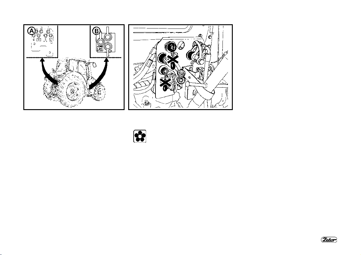
F_02_124
OUTER HYDRAULIC CIRCUIT
The outer circuit supplies pressurized oil
to hydraulic implements connected to the
outer outlets of the hydraulic system terminated with quick-couplers.
The sockets of the rear (A) as well as
front (B) quick-couplers have the inner
diameter of 12.5 mm and comply with the
international ISO 5675 standard.
HYDRAULIC SYSTEM
CONNECTING AND DISCONNECTING
QUICK-COUPLERS
When connecting and disconnecting the quick-couplers pay
increased attention with regard
to the residual oil that remains in
the socket or on the plug of the
quick-coupler.
For environmental reasons after
every disconnection of quickcouplers this residual oil must be
removed with any textile material.
83

HYDRAULIC SYSTEM
F_02_210
OIL QUANTITY DRAWN FROM THE
OUTER HYDRAULIC OUTLETS
For the maximum possible quantities of
drawn oil see the following table.
In case of higher consumption
the transmission oil level may
drop in such a way that the
transmission and hydraulic
pumps may aspirate air and there
is a danger of damaging the
pumps, mainly the transmission
pump, as well as the torque multiplier or the PTO clutch.
Type of work: On level ground
Max. oil consumption: 12 litres
Gearbox filling: Upper edge of the dip-
stick tab (B)
Type of work: On a slope
Max. oil consumption: 12 litres
Gearbox filling: Lower mark on the
cylindrical part of the dipstick (C),
transmission oil filling increased by 7
litres
Type of work: On level ground
Max. oil consumption: 27 litres
Gearbox filling: Upper mark on the
cylindrical part of the dipstick (D),
transmission oil filling increased by 15
litres, maximum permissible oil quantity in the gearbox
Type of work: On a slope
Max. oil consumption: 20 litres
Gearbox filling: Upper mark on the
cylindrical part of the dipstick (D),
transmission oil filling increased by 15
litres, maximum permissible oil quantity in the gearbox
Type of work: On level ground
Max. oil consumption: 8 litres
Gearbox filling: Lower edge of the
dipstick tab (A); minimum permissible
oil quantity in the gearbox
84

HYDRAULIC SYSTEM
XF173
HYDRAULIC DISTRIBUTOR OF THE OUTER HYDRAULIC CIRCUIT
A three-section or two-section distributor with four-position sections may be installed
in the tractor. The control levers of the sections are installed in the cab on the fender
of the right rear wheel. The first (right) section of the distributor is equipped with locking in pressure positions with hydraulic securing. In the case of the two-section and
three-section distributor it is the section controlling quick-couplers “1” and “2”. Outlet
“4” of the two-section distributor and “4” and “6” of the three-section one is additionally equipped with a check valve - used for the connection of a working branch of the
machine with an increased requirement for leakproofness - minimum lowering of the
implement e.g. during transport.
85

HYDRAULIC SYSTEM
F_02_96
DESCRIPTION OF THE FUNCTIONS OF INDIVIDUAL POSITIONS OF CONTROL LEVERS OF THE HYDRAULIC
DISTRIBUTOR
Lever position Function
1 Rear (upper) posi-
tion
2 Central position
3 Front (lower) posi-
tion
4 Front limit position
Note: The lever automatically returns from positions (1) and (3) to the neutral. Not applicable to the section with the kick-out func-
tion.
Always connect a single-acting cylinder to quick couplers
“2”, “4” ofthe two-section auxiliary distributor and
“2”, “4”, “6” of the three-section auxiliary distributor.
Always connect a double-acting cylinder to quick-couplers of one section.
Pressurized oil flows to quick-couplers: “2“, "4", "6"
Quick-couplers connected to the return line: “1“, “3“, “5“
Neutral
Pressurized oil flows to quick-couplers: "1", "3", "5"
Quick-couplers connected to the return line: “2“, “4“, “6“
With an increased force you can shift the control levers from position (3) further to the
front to position (4), i.e. floating (free) position, where the levers are locked. Both the
quick-couplers of each section are connected to the return line in this position.
86

F163b F168
REAR OUTLETS OF THE OUTER
HYDRAULIC CIRCUIT
In the tractor version that is not equipped
with the front outlets or the front threepoint hitch and that is equipped with
a - a three-section distributor the rear out-
lets are terminated with pressure
quick-couplers "1" to "6".
b - a two-section distributor the rear out-
lets are terminated with pressure
quick-couplers "1" to "4".
The third quick-coupler marked “0” is directly connected to the final drive housing and is designed for return oil from external hydraulic implements (e.g. from rotational hydraulic motors, etc.).
HYDRAULIC SYSTEM
FRONT OUTLETS OF THE OUTER
HYDRAULIC CIRCUIT
They are installed on a panel in the right
front part of the tractor. Their installation
is bound to a three-section distributor.
They are designed for the control of frontally attached adapters. The marking of
the outlets and their use is the same as
in the case of the rear outer outlets.
87

HYDRAULIC SYSTEM
CONNECTING MACHINES AND IMPLEMENTS TO THE OUTER HYDRAULIC
CIRCUIT
Connecting machines and implements consisting of more parts
During work with agricultural machines that consist of more parts (combinators, skids,
harrows) and that have side frames hat are hinged to the central frame and during
transport are folded to the vertical position by separate hydraulic cylinders controlled
by the outer hydraulic circuit of the tractor, the folding of the side frames must always
be controlled by the upward (backward) movement of the auxiliary distributor lever.
The “lifting” branches of the cylinders must be connected to quick-couplers “2”, “4” or
“6”.
Connecting a rotational hydraulic motor
If a rotational hydraulic motor is connected to an outer outlet of the hydraulic system,
its return branch must always be connected to quick-coupler “0”. In case of connection of the filling (pressure) branch to quick-coupler 1 or 2 the hydraulic motor is protected by the kick-out function against overloading. This function interrupts the operation of the hydraulic motor at the pressure value in the filling branch of 17.5 - 1.6
MPa.
Connecting a reversing hydraulic motor
A reversing rotary hydraulic motor must be connected to quick-couplers “1” and “2”
for functional reasons. However, relief valves must be inserted in both the branches
in this case as they can reliably limit the pressure peaks during the stopping of the
machine. The oil return lines from these valves are connected to quick-coupler "0".
88

ELECTRO-HYDRAULIC SYSTEM
Control element functions.......................................................................................... 90
Equipment “OFF” ......................................................................................................90
Blocking cancellation................................................................................................. 91
Quick sinking............................................................................................................. 92
Transport of implements............................................................................................ 92
Stop position ............................................................................................................. 92
Vibration compensator (damper)............................................................................... 93
Limitation of the upper position of the three-point hitch............................................. 93
Lowering speed......................................................................................................... 94
Free position ............................................................................................................. 94
Work in the field ........................................................................................................95
Using the rear control................................................................................................ 96
External control buttons of the electro-hydraulic system ........................................... 96
Using the buttons ......................................................................................................96
Indication of EHR-B errors ........................................................................................97
Description of minor errors of the EHR-B electro-hydraulic system........................... 98
Page
89
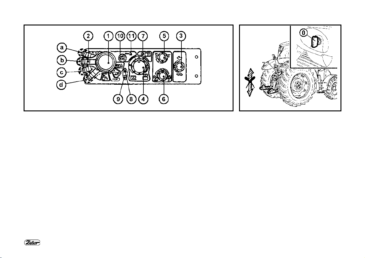
ELECTRO-HYDRAULIC SYSTEM
F_02_162 F_02_188
CONTROL ELEMENT FUNCTIONS
1. Switching of lifting
a - Transport, lifting
b - STOP
c - Adjustment, lowering (working)
d - Free position, quick sinking
- Spring-controlled automatic return of the lever to position (c)
2. Blocking (in the transport position)
3. Lowering speed
4. Setting the position of the lifting device
5. Upper position limitation
6. Stepless control setting (power → positional)
7. LED - diagnostic
8. LED - lifting
9. LED - lowering
10. Compensator switching (vibration dampening)
11. LED - vibration dampening “ON”
EQUIPMENT “OFF”
Electric installation deactivated with the
key of the switching box. The electronic
system is off, the lifting device is blocked.
90

F_02_164 F_02_163
BLOCKING CANCELLATION
When you switch on the electric installation with the key of the switching box (I),
the lifting device remains blocked electronically - the lifting and lowering function is deactivated; on the EHR-B control
panel the diagnostic LED (7) and the vibration dampening LED (11) shortly light
up - the system self-test is in progress.
The lifting LED (8) and the lowering LED
(9) are off. After a short time permanent
illumination of the diagnostic LED (7) indicates the state of EHR-B blocking.
If the diagnostic LED (7) is permanently
illuminated, the control circuits are disconnected.
ELECTRO-HYDRAULIC SYSTEM
The engine can only be started
if the engine (1) is in position
(b).
The EHR-B electro-hydraulic system is
only active when the engine is started.
Activation of the EHR-B system is only
possible when the lubrication indicator
has gone off.
The blocking can only be cancelled (system activated) with the engine running by
moving the lifting lever (1) to position (a)
- short-time switching is sufficient.
By moving the lever (1) to position (c)
you will bring the three-point hitch to the
position corresponding to the element
setting, i.e. the current position of controls (4), (5), (6).
91
After the activation of the system
EHR-B first for safety reasons
limits the lifting speed of the hydraulic arms.
When the hydraulic arms first
reach the selected position, this
safety limitation is cancelled and
then the lifting speed of the hydraulic arms is normal.

F_02_165 F_02_166 F_02_167
QUICK SINKING
Lever (1) in position (d) - free position.
You must hold the lever in this position;
after releasing the lever will return to position (c) - the system works in accordance with the setting of controls (3), (4),
(5) and (6).
ELECTRO-HYDRAULIC SYSTEM
TRANSPORT OF IMPLEMENTS
Shift the lifting lever (1) to position "a"
and block it with the moving latch (2).
Blocking the lifting lever (1) by the moving latch (2) in position (a):
A - Lever movement blocked
B - Lever movement not blocked
When the tractor with an attached
implement is stopped, the implement must be lowered onto the
ground (it must not be left in the
lifted position).
92
STOP POSITION
By moving the lever (1) to position (b) STOP position - you will immediately
stop the movement of the three-point
hitch.

ELECTRO-HYDRAULIC SYSTEM
F_02_168 F_02_169
VIBRATION COMPENSATOR (DAMPER)
It is used during transport of a heavy implement attached to the rear three-point hitch.
After activation of the vibration compensator (10) the arms of the rear three-point
hitch sink by approx. 4%, which allows oscillation of the arms in the range of approx.
8% of the lift. The upward oscillation is always limited by the position of the upper position limiter (5).
Advantages of active dampening of vibrations during transport of a heavy implement
attached to the rear three-point hitch.
1. Increased operation safety (the steering axle is not unloaded so much
2. Stabilization of the transported implement
3. Reduced dynamic stress of the hydraulic system and the rear three-point hitch
During the adjustment of the hitch for a single-axle semi-trailer the vibration
compensator must be off.
LIMITATION OF THE UPPER
POSITION OF THE THREE-POINT
HITCH
It is activated with the control (5). The
limitation can be implemented in the upper half of the three-point hitch lift.
93
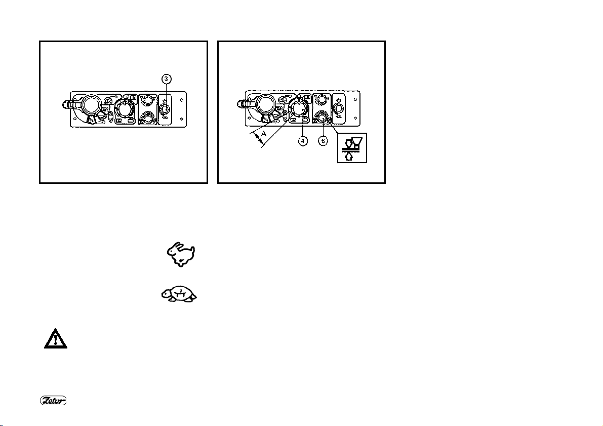
F_02_170 F_02_171
LOWERING SPEED
The lowering speed of the three-point
hitch is set with the control (3).
Symbol of the maximum
lowering speed
Symbol of the minimum
lowering speed
In the vibration dampening mode
and during the use of the rear
control buttons the lowering
speed setting is out of function.
ELECTRO-HYDRAULIC SYSTEM
FREE POSITION
For permanent work with free hydraulic
system, e.g. during work with a plough
with a support wheel the position of the
control (4) under the indication (A) and
the position of the control (6) at the positional control symbol is used.
94

WORK IN THE FIELD
Perform the steps described in the
“Blocking cancellation” section and set
the required position of the elements with
regard to the character of the planned
work. The control (4) is used to achieve
the depth of the implement. To set the
control type and their combination use
the control (6).
Power control symbol
Positional control symbol
ELECTRO-HYDRAULIC SYSTEM
F_02_172
The control activity (lifting and lowering)
can be monitored with the use of the indication diodes (8) and (9). At the dead
point shift the lever (1) to position (a) and
after reversing of the direction move it to
position (c) again. The control system will
return to the previous working position
(ploughing memory). The control (3) is
used to set the required lowering speed.
95

ELECTRO-HYDRAULIC SYSTEM
F_02_98 F_02_78 F_02_65
USING THE REAR CONTROL
The rear control is used to connect and
disconnect implements. The lifting
switching lever (1) on the EHR-B electrohydraulic control panel must be in position (b) or (c). The designation symbols
of buttons on both the tractor fenders
correspond to the movement direction of
the three-point hitch after their pressing.
The movement only lasts as long as the
button is held.
Every use of the rear control causes
blocking of the control system and the
“Blocking cancellation” must be repeated
- see page 130.
EXTERNAL CONTROL BUTTONS OF
THE ELECTRO-HYDRAULIC SYSTEM
1. Lifting
2. Lowering
The movement only lasts as long as the
buttons are held.
The external control buttons of the
electro-hydraulic system are functional without prior activation of
the system.
96
USING THE BUTTONS
When handling the three-point
hitch with the external control buttons the operator must stand out
of reach of the connected implement to avoid being caught or injured by the implement.

ELECTRO-HYDRAULIC SYSTEM
DESCRIPTION OF SIGNALS OF EHR-B ELECTRO-HYDRAULIC SYSTEM
ERRORS
Flashing combination
of the diagnostic LED
(7).
Error category Error description
F -02 -173
INDICATION OF EHR-B ERRORS
The electronic part of the electrohydraulic system continuously checks
proper functioning of the system. Possible errors are indicated by repeated
flashing combinations of the diagnostic
LED (7).
After the remedy of the error the diagnostic LED (7) goes off.
Permanent illumination of the diagnostic
LED (7) indicates the state of blocking of
the electro-hydraulic system.
Long pause
1x 1x
1x 2x
1x 3x
1x 4x
1x 5x
1x 6x
2x 2x
2x 3x
2x 4x
2x 8x
3x 1x
Have EHR-B errors repaired by a specialized work-
Short pause
No. of flashes
3x 2x
3x 4x
3x 6x
No. of flashes
Serious error
Moderately serious error
Minor error
Error with internal safety shutdown of the
electro-hydraulic system - the electrohydraulic system is out of operation - the
work with the tractor must be stopped
Error with internal safety shutdown of the
electro-hydraulic system - the electrohydraulic system is out of operation
The electro-hydraulic system works with a
limitation resulting from the error type
shop.
97
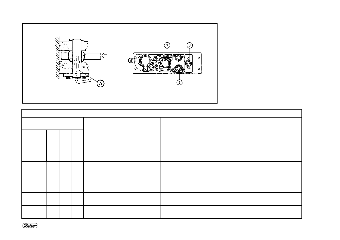
ELECTRO-HYDRAULIC SYSTEM
F_02_174
DESCRIPTION OF MINOR ERRORS OF THE EHR-B ELECTRO-HYDRAULIC SYSTEM
Flashing combination of
the diagnostic LED (7).
Error location Possible cause of the error
No. of
Long pause
3x 1x Right dynamometric pin (A) Faulty dynamometric pin
3x 2x Left dynamometric pin (A) Faulty contact or interrupted conductor of the dynamometric
flashes
No. of
flashes
Short pause
pin
Short-circuit of the dynamometric pin conductor
Possible overloading of the dynamometric pin
Faulty potentiometer of the control (3) 3x 4x Lowering speed control (3)
Faulty contact or interrupted conductor of the control
Faulty potentiometer of the switch (6) 3x 6x Control setting switch (6)
Faulty contact or interrupted conductor of the switch
98

HITCHES
Rear three-point hitch.............................................................................................. 100
Safety principles of working with the three-point hitch............................................. 100
Height adjustment of the lifting draw-bars ............................................................... 101
Fixed and free position of the lower hydraulic draw-bars ........................................ 101
Limiting draw-bars................................................................................................... 101
∗Lower draw-bars with extensible end pieces......................................................... 102
∗Lower draw-bars with CBM hooks......................................................................... 102
Securing the lower draw-bars with CBM hooks....................................................... 103
Upper draw-bar ....................................................................................................... 103
∗Front three-point hitch ........................................................................................... 104
Front three-point hitch control .................................................................................104
Adjusting the lowering rate of the front three-point hitch ......................................... 104
Hydraulic lock of the front three-point hitch ............................................................. 105
Working and transport position of the front three-point hitch................................... 105
Driving with agricultural machines attached to the front three-point hitch ............... 105
99
Page

HITCHES
REAR THREE-POINT HITCH
It is intended for attaching carried or
semi-carried agricultural machines and
implements with hitching points of ISO
category II.
Category II.
Hitch axis length 870 mm
∅ of openings of connect-
ing balls of the lower
draw-bars according to
ISO
∅ of the upper draw-bar
opening
1. Upper draw-bar
2. Left lifting draw-bar
3. Right lifting draw-bar
4. Limiting draw-bars
5. Lower draw-bars
E451
100
28 mm
25 mm
SAFETY PRINCIPLES OF WORKING
WITH THE THREE-POINT HITCH
Persons that are not authorized to
work with the attached implement
must not stand between the tractor
and the hitched machine (implement) - (A). Do not park the tractor
with an attached implement in the
lifted position (B). During a drive
without an implement the lower
draw-bars (5) must be connected
with springs and the upper drawbar (1) must be inserted into the
spring suspension! During transport
of implements the limiting drawbars (4) of the lower draw-bars
must be adjusted in such a way to
avoid unwanted lateral movement
of the implement!
G452
 Loading...