

Page 1

Adjustable Speed Drives
Page 2
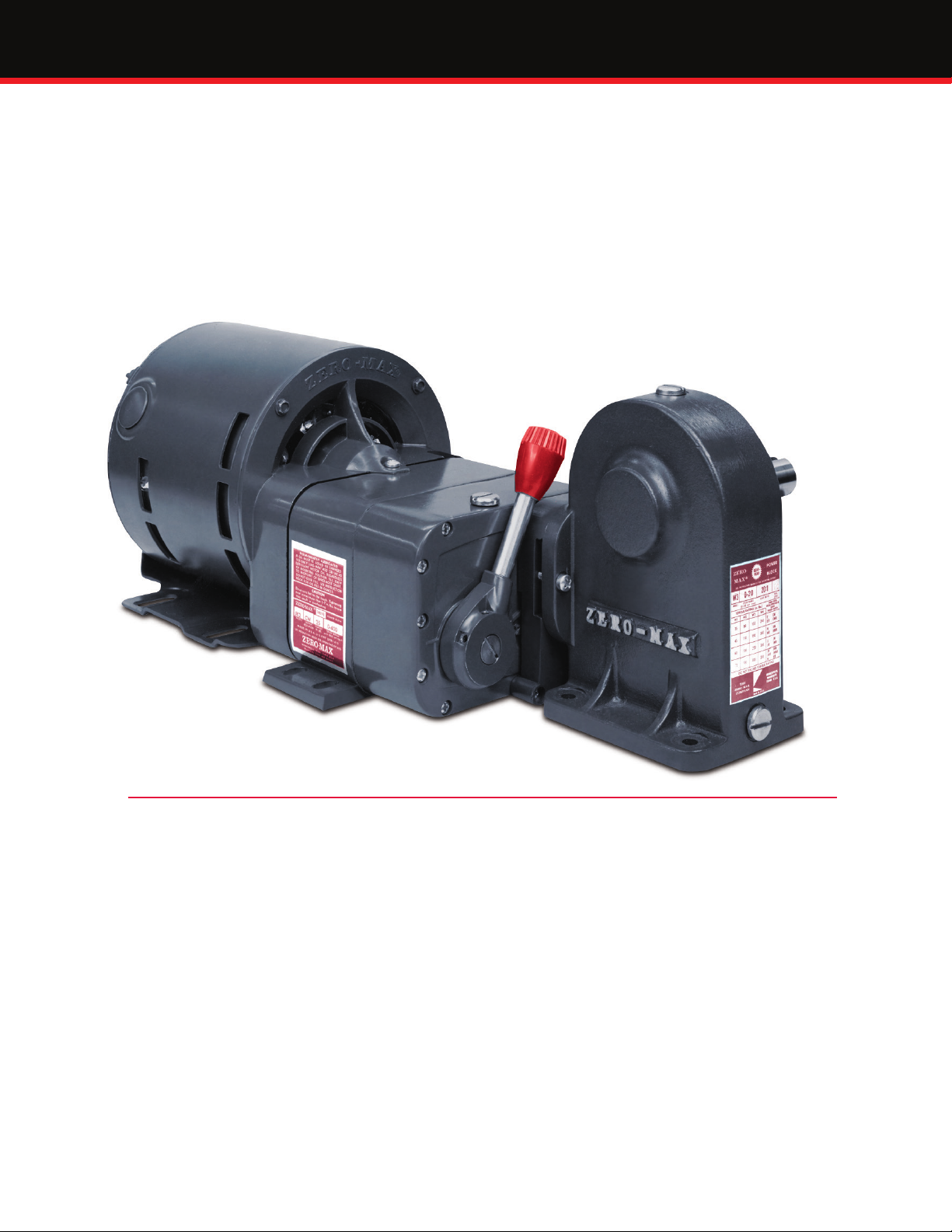
How The Zero-Max® Drive Works
A Zero-Max Drive is a mechanical adjustable speed drive.
Five sizes provide constant torque of 12 to 200 inch pounds
throughout the speed range. The speed range is innitely
variable from 0 to 1/4 of the input speed under full rated
load. This is generally stated as 0-400 RPM assuming an input
of 1800 RPM.
For lower speed/higher torque applications, some Zero-Max
Drives are available with right angle gearheads. Some
Zero-Max Drives may be purchased with standard electric
motors or they may be connected to any rotating power
source up to 2000 RPM. Speed adjustments are easily
made by moving a lever control through an arc or turning
the handwheel of a screw type control. In either case,
precise speed control settings are possible.
Over 1 million Zero-Max Drives have been put to work
in a wide variety of applications. They are available from
distributors in all major markets throughout the world.
Features ........................................... Benets
Compact ................................................ Easy to handle/compact
Simple to install ...................................... No special wiring/training
Simple operation .................................... Repeatable & easy to operate with lever or screw control
Use anywhere on machine ....................... Accepts input to 2,000 RPM. Ideal as a secondary drive
Constant torque ...................................... Delivers constant torque throughout the speed range
4:1 speed reduction ................................ Often usable without additional speed reduction
Change speed anytime ............................ Speed set-ups are made quickly and easily
Change speed frequently ......................... Permits slow or fast, small or large speed changes
Change speed continuously ..................... Ideal for dancer applications/constant speed changes
Leave at one setting ................................ No daily speed cycling
Accurate speed holding ........................... No “wear-in” period/constant speed operation
Accepts any input ................................... World’s most versatile, economical secondary drive
Goes to zero output ................................ Ideal for use as a clutch
Shaft/control/motor options ..................... Versatile
Innitely adjustable ................................. 0-400 RPM speed range with 1800 RPM input
1
Page 3

Match the Zero-Max® Drive to These Components
To achieve the exact performance characteristics
you desire, Zero-Max provides the following
matching components:
For Model E and JK Drives, a right angle gearhead and
selection of motors are available.
For models Y, QX and ZX Drives, C-Flange adapters are
available for connecting customer supplied motors to the
drive you have selected.
Unidirectional Drives
E Models
1, 2, 41 or 42
Torque Rating 12in. lbs.
Speed Range 0-400.
Normal Input 1/4-1/3 H.P.
JK Models
1, 2, 41 or 42
Torque Rating 25in. lbs.
Speed Range 0-400.
Normal Input 1/4-1/3 H.P.
Y Models
1, 2, 41, or 42
Torque Rating 60in. lbs.
Speed Range 0-400.
Normal Input 1/2 H.P.
Lever control is standard on all drives. Optional controls
include: screw control, extended screw control, extended
lever control, extended control shaft, microdial control,
plus atted and drilled control levers.
Direction of output rotation must be speci ed and is
independent of input direction. Model numbers ending
in “1” are CCW output, “2” are CW output and “3”
are reversible.
QX Models
1, 2, 41 or 42
Torque Rating 100in. lbs.
Speed Range 0-400.
Normal Input 3/4 H.P.
ZX Models
1, 2, 41 or 42
Torque Rating 200in. lbs.
Speed Range 0-400.
Normal Input 1-1/2H.P.
Reversible Drives Gearhead Motors
E Model 3
Torque Rating 12in. lbs.
Speed Range 400-0-400.
Normal Input 1/4-1/3 H.P.
JK Model 3
Torque Rating 25in.lbs.
Speed Range 400-0-400.
Normal Input 1/4-1/3 H.P.
Y Model 3
Torque Rating 60in.lbs.
Speed Range 0-400.
Normal Input 1/2 H.P.
Right angle gearheads
available for E and JK Models.
Right Angle - 4 Models
W1 4:1 W2 10:1
W3 20:1 W4 40:1
Many popular voltage, Hz,
phase and enclosures are
available for use with drive.
E Models 1, 2, 3/ JK
Models 1, 2 and 3
C-Face Adapters
MODEL CFY*
Includes coupling for
56 frame motor
.
MODEL CFQ
Includes coupling for
56 frame motor.
MODEL CFZ
Includes coupling for
56 frame motor.
All C-Face Adapters will accept 56, 143T and 145T frame motors.
*CFY adapter not compatible with Y3 reversible drive
2
Page 4
STANDARD
6 O'CLOCK
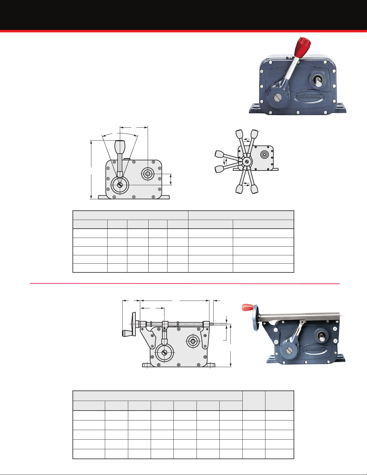
Controls for Zero-Max® Drives
Standard Lever Type Control
The lever control can be removed from its
customary 12 o’clock position and moved
to a 6 or 9 o’clock position on E and JK
Models and to any position on Y, QX and
ZX Models that will not interfere with
the casebody or shaft. Flatted and drilled,
as well as extended levers, are available
for easy attachment to any kind of remote
control, or for use on tension control
applications.
C
Standard Lever
B
9 O'CLOCK
A
D
Lever Control Dimensions Lever Torque
Drive Model A B C D (Running, no load) (Not running, full load)
E 5.25 52° 2.50 1.00 7 in. lbs. 20 in. lbs.
JK 5.25 52° 2.50 1.00 7 in. lbs. 35 in. lbs.
Y 6.75 52° 3.25 1.68 15 in. lbs. 66 in. lbs.
QX 8.25 54° 3.55 1.90 36 in. lbs. 90 in. lbs.
ZX 10.00 63° 3.06 2.40 50 in. lbs. 160 in. lbs.
Optional Screw Type Control
All Zero-Max Drives are available
A
B
C
with screw control. Screw controls
give very precise control of speed
and many kinds of remote control
attachments are easily made. They
are positive and easy to calibrate.
Kits are available for adding
screw control to drives in the eld.
The hand-wheel can be mounted
on either end of the screw.
Drive Model A B C D E F
E__SC 1.50 2.12 6.06 0.37 3.75 0.18 38 2 in. lbs.
JK__SC 1.50 2.12 6.06 0.37 3.75 0.18 38 2 in. lbs.
Y__SC 1.50 2.25 7.42 0.44 4.58 0.18 50 3 in. lbs.
QX__SC 2.12 2.87 8.81 0.37 5.87 0.25 68 4 in. lbs.
ZX__SC 2.12 6.12 12.31 0.50 7.44 0.31 91 4 in. lbs.
SCREW CONTROL DIMENSIONS
3
D
F
E
Screw Control
Number
of Screw
Turns
Screw
Torque
(inch-Lbs.)
Page 5

Controls for Zero-Max® Drives
Optional Microdial Type Control
Drive models E, JK, and Y are available with Microdial control.
The Microdial is an enhanced Screw control that will provide the
user with a numerical value that will correspond to a given speed
setting. For added exibility, these units can be ordered with the
Microdial counter on either end of the control. The Microdial
is ideal for applications that require the speed setting to be
adjusted often and need a high level of repeatability. Kits are
available for adding the Microdial control to drives in the eld.
Microdial Control*
*LH (left hand) conguration shown
Numerical
G
C
Counter
H
E
I
Drive Model A C E G H I J
E__MD-__ 1.50 6.12 3.75 1.66 1.97 0.25 2.14 0-76
JK__MD-__ 1.50 6.12 3.75 1.66 1.97 0.25 2.14 0-76
Y__MD-__ 1.50 7.42 4.58 1.66 1.97 0.34 2.14 0-100
Type MD-LH
MICRODIAL DIMENSIONS
Drive Operating Characteristics
Input Speed should not exceed 2,000
RPM. There is no minimum, but as input
speeds approach zero, slight variations
in the angular velocity of the output
may become noticeable. It is much
better to use higher input speeds and
take as much reduction as possible
from the output shaft to maximize
precise speed control. Direction of the
input does not affect direction of output
but does affect the speed range and
performance of the Zero-Max Drive. The
recommended input rotation direction
in relation to output is given below.
If output speeds are substantially in
excess of rated speeds or if the drive is
noisy or vibrating at top speed, the nonpreferred direction input is probably
being used. Try reversing the motor so
the input is in the other direction.
Output Speed is innitely adjustable
from 0 to 1/4th of the input speed.
Speeds can be maintained or repeated
with accuracy of 1% or less of
maximum speed in the upper 90% of
the range providing output load and
input speed are constant.
Zero-Max Drives
Models vary in their ability to give
absolute zero under light loads. All
models go to zero output speed under
full rated load.Output Torque ratings
listed for various models are constant
throughout the speed range and
assume an input speed of 1800 RPM.
The drives are designed for continuous
duty running at one speed, a variety
of speeds or continuous speed cycling.
Additional output torque may be
gained by lowering input speed. In
general, the torque rating of all models
may be increased 25% if the input
speed is 900 RPM or lower.
Temperature
A rise of 40° C above ambient may be
expected in the drive assuming input
speed of 1800 RPM. This temperature
will generate surface heat too hot for
continued skin contact. This does not
indicate a malfunction nor does it affect
the performance of the drive. The drives
are built to withstand high operating
temperatures but they should never
exceed 90° C.
A
J
A
J
C
G
H
E
Type MD-RH
Numerical
Counter
Range
Thrust
Model
E & JK 20 12 25
*Note: At mid-point of Input and Output Shafts
Overhung Load Pounds
Output Input
Y 40 30 75
QX 50 40 100
ZX 400 100 400
W 400 – 500
*
Pounds
Load
Control Linearity
Movement of the Zero-Max speed
control lever or rotation of the screw
control produces a change in output
speed that is non-linear. A typical
speed-control curve of a Zero-Max
Drive under full rated load is shown
in the chart below.
100
80
60
40
20
At Full Rated Load
r--
r--
And
1800 RPM Input Speed
,,,
V
/
,....
~
~
0510 15 20 25 30 35 40 45 50
-
/
I/
/
4
Page 6

How to Select a Zero-Max® Drive
1. Start By Determining The Torque Required To Start And Run Your Machine. This may be the
most important step in selecting the best drive model for your application. All Zero-Max
Drives are rated for constant torque and variable horsepower throughout the speed range.
Be sure to consider the type of machine and apply the proper service factor.
2. Determine Speed Range Required For Your Machine Processes. The Zero-Max Drive speed
range of 0-400 RPM is given assuming an input speed of 1800 RPM and full load on the
output shaft. The selection of input speed and direction of input will have an effect on the
nal output speed. Lower input speeds reduce the speed range proportionately.
Running the input in the non-preferred direction substantially increases the speed range
but may result in higher operating temperature. For best results, run the Zero-Max in the
preferred direction and match the speed range to your machine requirement. Take as much
reduction as possible, from the output shaft to the load, to provide adequate torque and to
maximize accuracy of speed control.
3. Determine Output Shaft Rotation. This is done by looking directly at the end of the output
shaft. Model numbers ending in “1” are CCW output, “2” are CW output and “3” are
reversible. Use of the Zero-Max right angle gearhead does not change the direction of
rotation of the nal output shaft.
4. Select The Proper Method Of Providing Input Speed To The Zero-Max Drive. If the Zero-Max
Drive is being used as a secondary drive unit, input is best provided by a timing belt drive.
Other common methods include shaft couplings, chain and sprocket drive, V-belt, and
at belt drives which are less desirable because of the potential for excessive overhung
loading on the shaft.
In any case, care should be taken to mount pulleys, sprockets etc. as close to the Zero-Max
Drive case as possible to minimize overhung loads on the shafts. If a Zero-Max motor is to
be used, select the standard motor from the chart on page 12.
5. Determine The Type Of Control Best Suited To Your Application. Lever control is supplied as
standard with all models of Zero-Max Drives. Other controls are available as discussed on
page 3 and 4. The lever control is best suited for applications requiring rapid and frequent
speed changes. The screw control is best suited for precise settings and speed repeating.
Series Shaft Options Available Output Torque Recommended Input HP
E 1, 2, 3, 41, 42 12 In-Lbs 1.4 Nm 1/4 HP
JK 1, 2, 3, 41, 42 25 In-Lbs 2.8 Nm 1/3 HP
Y 1, 2, 3, 41, 42 60 In-Lbs 6.8 Nm 1/2 HP
QX 1, 2, 41, 42 100 In-Lbs 11.3 Nm 3/4 HP
ZX 1, 2, 41, 42 200 In-Lbs 22.6 Nm 1 1/2 HP
5
Page 7
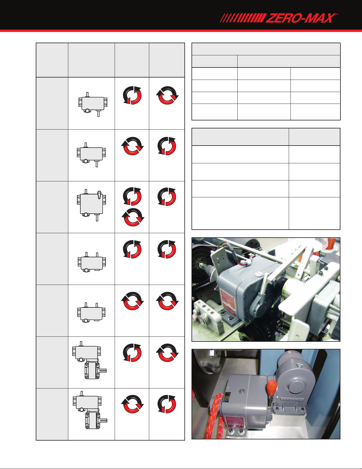
Zero-Max® Drives
Type
E1, JK1,
Y1, QX1,
ZX1
E2, JK2,
Y2, QX2,
ZX2
E3, JK3,
Y3
Note: Shaft
rotations are
always referenced
by viewing the end
of that shaft
Input
Output
Rotation
CCW CW
q ''
Output
Input
Output
Input
Output
Preferred
Input
Rotation
CW CCW
Both CCW
Service Factors
Type of Load Type of Duty
Uniform 8 to 10 hrs./day 1.0 24 hrs./day 1.5
Moderate Shock 1.5 2.0
Heavy Shock 2.0 3.0
Reversing Service 2.0 3.0
Types of Applications
General machines with ball
or roller bearings
General machines
with sleeve bearings
Conveyors and machines
with excessive sliding friction
Machines that have “high” load
spots in their cycle like printing,
punch presses and machines
with cams /crank-operation.
Running Torque
Multiplier
1.2–1.3
1.3–1.6
1.6–2.5
2.5–6.0
E41,
JK41,
Y41,
QX41,
ZX41
E42,
JK42,
Y42,
QX42,
ZX42
E1-W_ ,
JK1-W_
Input Output
c:)
Input
Output
c:)
Input
Output
Input
CCW CCW
'' ''
CW CW
CCW CW
''
CW CCW
====~~
~~~~
E2-W_ ,
JK2-W_
''
Output
6
Page 8
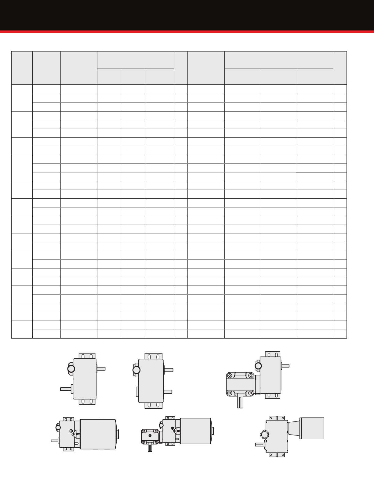
Torque and Speed Range Selection Chart
Standard Zero-Max Drives -- Order By Complete Model Number.
Torque
Rating
(In.
Lbs.)
12
25
35
60
75
90
100
155
190
200
240
300
300
Speed
Range
w/ 1800
RPM
input
0-400 A E1 E2 - 4 D E1-M3 E2-M3 - 18
400-0-400 A - - E3 5 D - - E3-M3 19
0-400 B E41 E42 - 4 - - - - -
0-400 A JK1 JK2 - 6 D JK1-M3 JK2-M3 - 20
400-0-400 A - - JK3 6 D - - JK3-M3 20
0-400 B JK41 JK42 - 6 - - - - -
0-100 C E1-W1 E2-W1 - 9 E E1-W1-M3 E2-W1-M3 - 23
100-0-100 C - - E3-W1 10 E - - E3-W1-M3 24
0-400 A Y1 Y2 - 10 F Y1-CFY Y2-CFY - 16
400-0-400 A - - Y3 15 - - - - -
0-400 B Y41 Y42 - 10 - - - - -
0-100 C JK1-W1 JK2-W1 - 11 E JK1-W1-M3 JK2-W1-M3 - 25
10-0-100 C - - JK3-W1 11 E - - JK3-W1-M3 25
0-40 C E1-W2 E2-W2 - 9 E E1-W2-M3 E2-W2-M3 - 23
40-0-40 C - - E3-W2 10 E - - E3-W2-M3 24
0-400 A QX1 QX2 - 21 F QX1-CFQ QX2-CFQ - 26
0-400 B QX41 QX42 - 21 - - - - -
0-20 C E1-W3 E2-W3 - 9 E E1-W1-M3 E2-W3-M3 - 23
20-0-20 C - - E3-W3 10 E - - E3-W3-M3 24
0-40 C JK1-W2 JK2-W2 - 11 E JK1-W2-M3 JK2-W2-M3 - 25
40-0-40 C - - JK3-W2 11 E - - JK3-W2-M3 25
0-400 A ZX1 ZX2 - 32 F ZX1-CFZ ZX2-CFZ - 37
0-400 B ZX41 ZX42 - 32 - - - - -
0-10 C E1-W4 E2-W4 - 9 E E1-W4-M3 E2-W4-M3 - 23
10-0-10 C - - E3-W4 10 E - - E3-W4-M3 24
0-20 C JK1-W3 JK2-W3 - 11 E JK1-W3-M3 JK2-W3-M3 - 25
20-0-20 C - - JK3-W3 11 E - - JK-W3-M3 25
0-10 C JK1-W4 JK2-W4 - 11 E JK1-W4-M3 JK2-W4-M3 - 25
10-0-10 C - - JK3-W4 11 E - - JK3-W4-M3 25
Shaft
Arrangement
Model Number - without
Motor Output Shaft Rotation
CCW CW Reverse CCW CW Reverse
Net
Wt.
Lbs.
Shaft
Arrangement
Model Number - with Motor or
C-Flange Adapter Output Shaft Rotation
Net
Wt.
Lbs.
Standard Shaft Arrangements
Output
Output
Input
A
D
Output
Input
B
Output
E
7
Input
C
Output
F
Output
Page 9

U
XC
A
P
XH
Zero-Max® Drives
Standard Drives Models E, JK, Y, QX and ZX Dimensions
XB
I
H
A 6.37 6.37 6.37 6.37 8.50 8.50 10.25 10.25 12.62 12.62
AG 2.84 2.84 3.98 3.98 4.70 4.70 6.81 6.81 6.75 6.75
AT 0.31 0.31 0.31 0.31 0.31 0.31 0.37 0.37 0.50 0.50
B 2.00 2.00 2.00 2.00 2.87 2.87 3.00 3.00 4.75 4.75
BA 1.22 1.22 2.34 2.34 2.28 2.28 2.41 2.41 1.50 1.50
D 2.25 2.25 2.25 2.25 3.00 3.00 3.50 3.50 4.50 4.50
FG 1.12 1.12 1.12 1.12 1.50 1.50 2.00 2.00 2.00 2.00
FU 0.375 0.375 0.375 0.375 0.500 0.500 0.625 0.625 0.875 0.875
H (slots) 0.28 dia. 0.28 dia. 0.28 dia. 0.28 dia. 0.40 dia. 0.40 dia. 0.40 dia. 0.40 dia. 0.53 dia. 0.53 dia.
I 0.25 0.25 0.25 0.25 0.22 0.22 0.10 0.10 0.0 0.0
N 1.56 --- 1.56 --- 2.00 --- 3.00 --- 3.25 ---
N* --- 1.12 --- 1.12 --- 2.00 --- 2.87 --- 3.25
O 3.50 3.50 3.50 3.50 4.50 4.50 5.50 5.50 7.00 7.00
O* 5.25 5.25 5.25 5.25 6.75 6.75 8.25 8.25 10.00 10.00
P 5.00 5.00 5.00 5.00 6.50 6.50 8.00 8.00 10.00 10.00
U 0.375 --- 0.375 --- 0.625 --- 0.750 --- 1.00 ---
U* --- 0.375 --- 0.375 --- 0.625 --- 0.750 --- 1.00
XA 1.25 1.25 1.25 1.25 1.53 1.53 2.00 2.00 2.50 2.50
XB 2.50 2.50 2.50 2.50 3.50 3.50 4.00 4.00 5.00 5.00
XC 0.00 0.00 0.00 0.00 0.25 0.25 0.45 0.45 1.94 1.94
XD 1.25 1.25 1.25 1.25 1.31 1.31 1.60 1.60 2.09 2.09
XE 0.56 0.56 0.56 0.56 0.75 0.75 0.91 0.91 1.00 1.00
XF 0.72 0.72 1.84 1.84 1.78 1.78 1.89 1.89 1.00 1.00
XG 0.50 0.50 0.50 0.50 0.50 0.50 0.50 0.50 0.50 0.50
XH 0.69 0.69 0.69 0.69 1.00 1.00 1.13 1.13 1.31 1.31
ZE 5.50 5.50 5.50 5.50 7.50 7.50 9.25 9.25 11.25 11.25
ZF 1.00 1.00 1.00 1.00 1.87 1.87 2.00 2.00 3.75 3.75
FG
E1&2 E 41&42 JK1&2 JK 41&42 Y1&2 Y 41&42 QX1&2 QX 41&42 ZX1&2 ZX 41&42
U*FU
N*
XG
ZF
BA
AG
N
~~~=~
ZE
XA
J_
-.
1r
AT
O
!
O*
D
XD
8
Page 10

XB
P
AG
P
C
Drives Dimensions
Reverse Drives Models E3, JK3 and Y3 Dimensions
REVERSE
LEVER
D
XD
A
A B D
E3 6.37 2.00 2.25
JK3 6.37 2.00 2.25
Y3 8.50 2.87 3.00
O*
O
AT
H
slots
N O O* P U AG AT BA FG FU XA XB NC XD XE XF XG ZE ZF
0.28
1.56 3.50 4.50 5.00 0.375 3.23 0.31 1.59 1.12 0.375 1.25 2.50 1.00 1.25 0.56 0.50 1.00 5.50 1.00
dia.
0.28
1.68 3.50 4.50 5.00 0.375 4.37 0.31 2.71 1.12 0.375 1.25 2.50 2.12 1.25 0.56 0.50 1.00 5.50 1.00
dia.
0.40
2.00 4.53 5.53 6.60 0.625 5.83 0.31 3.39 1.50 0.500 1.53 3.50 2.89 1.31 0.75 0.50 1.50 7.50 1.87
dia.
Motorized Drives Models E and JK Dimensions
XB
XA
XFXE
BA
E3 and JK3
ONLY
ZF
FG
FU
ZE
U
XA
XG
H
N NC B
U
O'
XD
XC
D
AO
AB
ZE
AG
A
A D H (slots) H" (slots)* P U AE AO AT BA XA XB XC XD XE XF XH ZE ZF
E1 & E2 6.37 2.25 0.28 dia. 0.34 dia. 5.62 0.375 3.18 2.75 0.31 1.22 1.25 5.00 3.50 4.50 0.56 1.00 2.75 5.50 1.00
E3 6.37 2.25 0.28 dia. 0.34 dia. 5.62 0.375 3.18 2.75 0.31 1.59 1.25 5.00 3.50 4.50 0.56 1.00 2.75 5.50 1.00
JK1 & JK2 6.37 2.25 0.28 dia. 0.34 dia. 5.62 0.375 3.18 2.75 0.31 2.34 1.25 5.00 3.50 4.50 0.56 1.00 2.75 5.50 1.00
JK3 6.37 2.25 0.28 dia. 0.34 dia. 5.62 0.375 3.18 2.75 0.31 2.71 1.25 5.00 3.50 4.50 0.56 1.00 2.75 5.50 1.00
*Motor slots are centered 4.25 apart.
Z.M.
Motor
M3
M9 DP 1/3 230 60 1 12.95 13.35 14.09 14.47 4.37 5.81
M42L** DP 1/3 230/460 60 3 15.07 15.48 16.20 16.57 4.42 5.81
M5 TEFC 1/4 115 60 1 14.06 14.38 15.18 15.53 4.37 6.39
M45 TEFC 1/4 230/460 60 3 14.06 14.38 15.18 15.53 4.37 6.39
**M42L (long) has replaced M42 motor. Contact factory with questions.
Other motors are available, please contact the factory with your requirements.
Used
With ENCL
DP 1/3 115 60 1 12.95 13.35 14.09 14.47 4.37 5.81
E
or
JK
Horse
Power Voltage Hz Phase
XF
XE
AT'
BA
ZF
H
XG
C DIMENSION
w/ E1
& E2 w/ E3
XH
w/ JK1
& JK2 w/ JK3
H"
XG O’
9
Page 11

XD
XE
XF
*
C
N
XA
XB
XC
AG
XG
XF
*
AG
XH
XB
XA
N
C
XG
A A
D
D
XG
XF
*
AG
XH
XB
XA
N
C
A
D
Drives Dimensions
Drives with C-Flange Adapters Models Y, QX and ZX Dimensions
D
N
XA
,_
XB
XC
AG
1=
Model Y
A
XDXG
XF
XE
I
--~~
------~~~~~-0
*
C
1
Model QX Model ZX
D
J_
q::t:::::::::t:~
XG
-
XD
N
---.----
XA
XB
XC
AG
.._____________o
A
XE
-
XF
I
~l
-- -
~,
J
A
D
*
*
XG
XF
N
l
XA
XB
AG
..____J
XH
j -
C
i=::::::==i
C
A C D N AG XA XB XC XD XE XF XG
Y 9.31 10.37 3.50 2.00 8.37 2.28 4.15 6.22 3.25 6.50 7.00 0.50
QX 10.37 13.97 3.50 3.00 11.10 2.39 4.41 8.37 1.63 7.12 8.63 0.63
ZX 12.12 14.12 4.50 3.25 10.88 1.50 5.25 - - - 10.62 0.62
*Accepts 56, 143T and 145T frame, C-face motor.
Note: CFY adapter not compatible with Y3 reversible drive
CFY CFQ CFZ
10
Page 12

Drives Dimensions
Standard Drives with Right Angle
Gearhead Dimensions
E1& E2 E3 JK1 & JK2 JK3
Right Angle Gearheads (W)
A 7.68 7.68 7.68 7.68
C' 8.53 8.90 9.65 10.02
D 3.81 3.81 3.81 3.81
H (slots) 0.28 dia. 0.28 dia. 0.28 dia. 0.28 dia.
==
H" (slots)* 0.34 dia. 0.34 dia. 0.34 dia. 0.34 dia.
1--------------f---------------------'
*Motor slots are centered 4.25 apart
========
H' 0.26 dia. 0.26 dia. 0.26 dia. 0.26 dia.
N 2.00 2.00 2.00 2.00
O 5.84 5.84 5.84 5.84
P 5.62 5.62 5.62 5.62
U 0.750 0.750 0.750 0.750
AB 3.18 3.18 3.18 3.18
AG 6.37 6.37 6.37 6.37
AO 2.75 2.75 2.75 2.75
AT 0.35 0.35 0.35 0.35
AT' 0.31 0.31 0.31 0.31
XA 0.06 0.06 0.06 0.06
XB 5.00 5.00 5.00 5.00
XC 2.38 2.38 2.38 2.38
XD 0.43 0.43 0.43 0.43
XE 1.43 1.43 1.43 1.43
XF 2.87 2.87 2.87 2.87
XH 2.43 2.84 3.59 3.93
XI 1.00 1.00 1.00 1.00
XK 2.75 2.75 2.75 2.75
XL 2.43 2.43 2.43 2.43
XN - 4.50 - 4.50
ZE 5.50 5.50 5.50 5.50
==
E and JK Drives with Right Angle Gearheads
(W) Dimensions with Motor
C
C'
XL
1-
.-------+--
~~
l
O
j
~
AT
FX XD
-1
XE
E3 AND
JK3 ONLY
XN
~~~
XI
P
XB
ZE
AG
A
H
XC
XG
XK
U
N
H'
XH
AO
AB
AT'
XA
O'
H"
D
SHAFT AND KEYWAY DETAILS
Model Output Input
E & JK Flat 1/16" deep x 1-1/8" Flat 1/16" deep x 3/4"
Y Keyway 3/16" x 1-5/8" Flat 1/16" deep x 1"
QX Keyway 3/16" x 2-1/2" Keyway 3/16" x 1-1/2"
ZX Keyway 1/4" x 2-1/8" Keyway 3/16" x 1-1/4"
W Keyway 3/16" x 1-1/4" Hollow Shaft
Specications are subject to change. When dimensions are
critical, detailed drawings should be obtained from the factory.
Motor* w/E1
&
M9 15.95 16.33 17.06 17.45 4.37 5.81
M3
M42L** 18.05 18.43 19.18 19.56 4.42 5.81
M5 16.75 17.25 18.00 18.38 4.37 6.39
M45 16.75 17.25 18.00 18.38 4.37 6.39
*See page 12 for motor data.
**M42L (long) has replaced M42 motor. Contact factory with questions.
11
MOTORS*
Right Angle Gearheads (W)
C XG O’
&
E2 w/E3 w/JK1 & JK2 w/JK3
Page 13

Ordering Model Code
□
Model
E
Y
Output
Torque
12 in-lbs
25 in-lbs
60 in-lbs
100 in-lbs
200 in-lbs
Code
JK
QX
ZX
□ □ □
Code
* Reversing drives are available in sizes
E, JK, and Y only.
1
2
3*
41
42
Example:
Con guration
Output
Rotation
Counter
Clockwise
Clockwise
Both CCW
and CW
Counter
Clockwise
Clockwise
Shaft
Con guration
Input
Output
Input
Output
Control Options
Code Output Torque
Omit
SC
MD-LH
MD-RH
Note: Microdial controls not
available on QX and ZX
models as standard.
·------------------------------------
1
I
Standard
Control Lever
Screw Control
Microdial
(Left Hand
Installation)
Microdial
(Right Hand
Installation)
Integrated Electric Motor
(Available for E and JK drives only)
Right Angle Gear Reducer
(Available for E and JK drives only)
Code
Omit
W1
W2
W3
W4
Gear Ratio
□
I
·--
None
4 : 1
10 : 1
20 : 1
40 : 1
• Required output torque is 20 in-lbs.
• Output shaft rotation is clockwise.
• Input and output shaft arrangement
to be on same side of housing.
• Screw control option is desired.
• Gear reduction is not required.
• Integrated motor is not required
Model Code is JK42SC
C-Face Adapters
Part Number Description
CFY*
CFQ Designed to mount a 56C frame motors to a QX drive
CFZ Designed to mount a 56C frame motors to a ZX drive
Note: All kits include the shaft coupling.
*CFY adapter not compatible with Y3 reversible drive
Designed to mount a 56C frame motors to a Y drive
Code HP Voltage Phase Enclosure
Omit
M3
M9
M42L
M5
M45
1/3 115 1 Drip Proof
1/3 230 1 Drip Proof
1/3 230/460 3 Drip Proof
1/4 115 1
1/4 230/460 3
MODEL CFQ MODEL CFZMODEL CFY
None
Totally Enclosed
Fan Cooled (TEFC)
Totally Enclosed
Fan Cooled (TEFC)
12
Page 14
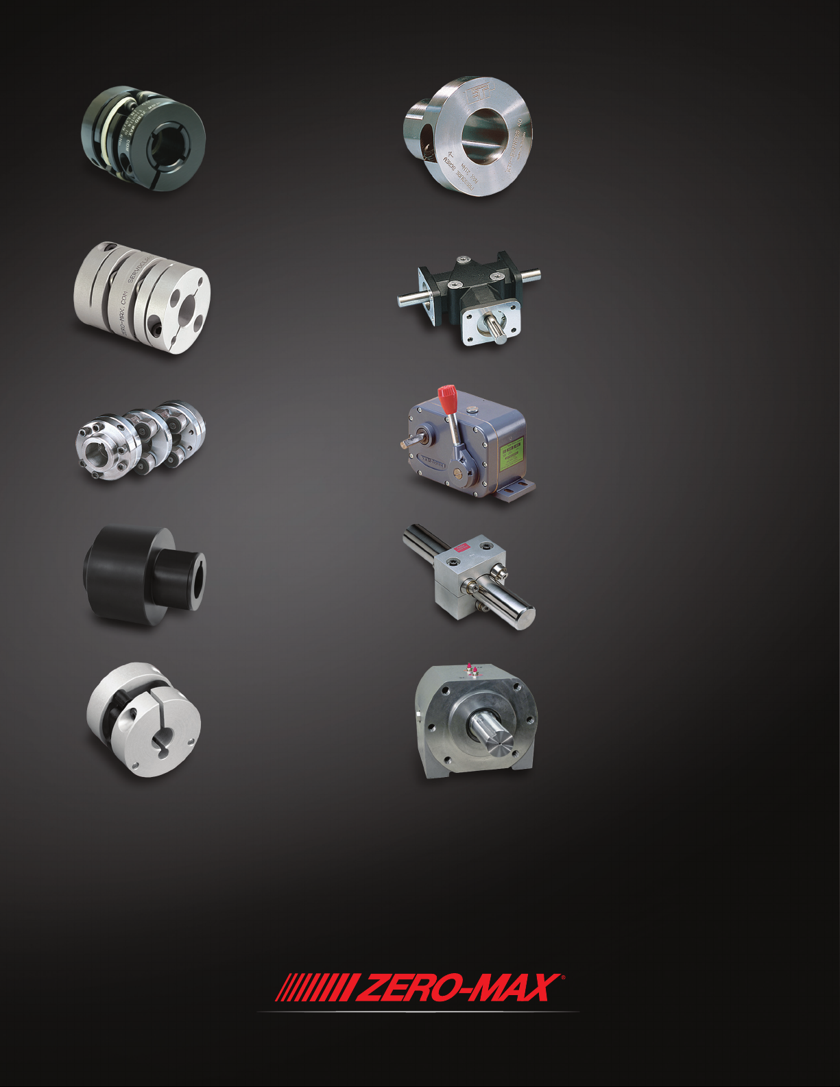
PRECISE. RELIABLE. ROBUST. AVAILABLE.
CD® Couplings
High-performance couplings that
outperform and outlast bellows
and steel disc designs. The unique
design of the composite disc
enables the CD Couplings to
withstand punishing applications
and deliver high precision
performance. Fully Customizable.
ServoClass® Couplings
Designed for demanding
servomotor applications. Zero
backlash, high torsional stiffness,
high speed design. Features
exible metal discs for high
misalignment capacity and keyless
clamp-type mounting hubs.
Schmidt Offset Couplings
Designed to handle high amounts
(up to 17") of parallel shaft offset
with constant angular velocity.
Standard models with torque
capacities up to 459,000 in-lbs
and extensive custom capabilities.
Keyless Shaft Locking Devices
ETP® keyless connections and
Posi-Lok® keyless bushings provide
quick, easy and accurate assembly
of mounted shaft components. Both
inch and metric bore sizes are
available from stock.
Crown Gear Drives
Available in 5-sizes, 3 congurations,
and with 1:1 and 2:1 ratios. High
quality AGMA class 10 spiral bevel
gears. Stainless steel shafts and either
black anodized or IP65-Rated nickelplated aluminum housing.
Adjustable Speed Drives
Easy to install and maintenance free.
Zero-Max
variable speeds from 0 rpm to 1/4
of input rpm. 5 models with torque
ranges from 12 in-lbs to 200 in-lbs.
®
Drives offer innitely
Overload Safety Couplings
Torque Tender® Couplings provide
reliable overload protection in any
mechanical power transmission
system. Full selection of styles and
sizes with set-point torque ranges
from 3 to 3,000 in-lbs.
Control-Flex® Couplings
Zero backlash couplings designed
for encoder and instrumentation
type applications. Features high
misalignment capacity, constant
velocity, and an electrically
Roh’Lix® Linear Actuators
Simple conversion of rotary motion into
precise linear motion. Available in ve
models and multiple congurations.
Roh’Lix actuators have thrust ratings
from 5 to 200 lbs. All models feature
built-in overload protection.
OHLA® Overhung Load Adaptors
Designed to protect hydraulic motors
and pumps from radial/axial loads and
to provide additional seal protection.
11 models available for mounts from
SAE A to SAE F. Fully customizable.
isolated hub design.
Warranty. Zero-Max, Inc. the manufacturer, warrants that for a period of 12 months from date of shipment it will repair, or at its option, replace any new apparatus which proves defective in material or workmanship, or
which does not conform to applicable drawings and specications approved by the manufacturer. All repairs and replacements shall be F.O.B. factory. All claims must be made in writing to the manufacturer.
and under no circumstances shall manufacturer be liable for (a) damages in shipment; (b) failures or damages due to misuse, abuse, improper installation or abnormal conditions of temperature, dirt, water or corrosives; (c)
failures due to operation, intentional or otherwise, above rated capacities, and (d) non-authorized expenses for removal, inspection, transportation, repair or rework. Nor shall manufacturer ever be liable for consequential
and incidental damages, or in any amount greater than the purchase price of the apparatus.
or change shall create any liability on the part of Zero-Max, Inc. in respect to its products in the hands of customers or products on order not incorporating such changes even though delivered after any such change.
warranty is in LIEU OF ALL OTHER WARRANTIES, EXPRESS OR IMPLIED, INCLUDING (BUT NOT LIMITED TO) ANY IMPLIED WARRANTIES OF MERCHANTABILITY OR FITNESS FOR A PARTICULAR PURPOSE. THE TERMS OF THIS
WARRANTY CONSTITUTE ALL BUYER’S OR USER’S SOLE AND EXCLUSIVE REMEDY, AND ARE IN LIEU OF ANY RIGHT TO RECOVER FOR NEGLIGENCE, BREACH OF WARRANTY, STRICT TORT LIABILITY OR UPON ANY OTHER THEORY.
Any legal proceedings arising out of the sale or use of this apparatus must be commenced within 18 months of the date of purchase.
recommendations.
Zero-Max®, CD®, ETP®, ServoClass®, Torq-Tender®, Control-Flex®, Posi-Lok®, Roh’Lix® , Crown® , Schmidt® and OHLA® are registered trademarks of Zero-Max, Inc. In U.S.A.
•
Zero Max, Inc. reserves the right to discontinue models or to change specications at any time without notice. No discontinuance
•
CAUTION: Rotating equipment must be guarded. Also refer to OSHA specications and
•
©Zero-Max, Inc., All Rights Reserved
In no event
•
This
•
Printed in U.S.A., Rev2.01W
 Loading...