

Page 1
www.zephyronline.com
Installation Guide
Tempest, Tidal I, Tidal II
Recirculating Kit
ZRC-7000C
ZRC-7036C
ZRC-7042C
ZRC-7048C
JAN21.0201 © Zephyr Ventilation LLC.
READ AND SAVE THESE INSTRUCTIONS
Page 2
MODELS: ZRC-7000C, ZRC-7036C, ZRC-7042C, ZRC-7048C
PARTS SUPPLIED
1 - Air diverter box
2 - Carbon lter cartidges (3 - ZRC-7048C)
2 - Carbon lter adapters (3 - ZRC-7048C)
1 - Hardware package
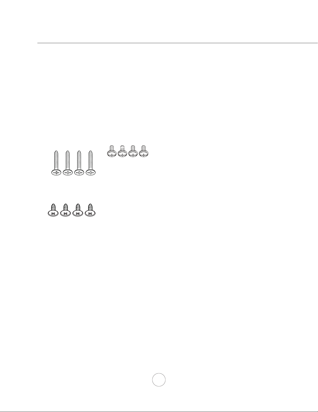
HARDWARE PACKAGE CONTENTS
www.zephyronline.com
List of Materials
#6 x 1” (4)
3/16 x 3/8” (4)
(6) for 42” & 48”
M4 x 8 (4)
PARTS NOT SUPPLIED
- Ducting, conduit and all installation tools
- Cable connector (if required by local codes)
REPLACEMENT PARTS
DESCRIPTION PART #
Replacement Parts
Charcoal Filter (each) Z0F-C002
To order parts, visit us online at http://store.zephyronline.com or call us at 1.888.880.8368
2
Page 3

TOP
27-1/4” or 33-1/4” or 39-3/16” or 45-3/16”
11-13/16”
42” & 48”
Models only
1-3/8”
2-9/16”
1-3/16”
7/8”
7-1/2”
2-9/16”
C/L
FRONT
29-15/16” or 35-15/16” or 41-15/16” or 47-15/16”
SIDE
12”
Installation – Specications
4”
3
Page 4

Mounting the air diverter box
FOR USE WITH AK7000CS, AK7300AS, AK7400AS,
AK7500CS, AK7036CS, AK7336AS, AK7436AS
AK7536CS, AK7042CS, AK7542CS, AK7048CS,
AK7448AS, and AK7548CS ONLY
FOR USE WITH SINGLE INTERNAL BLOWER ONLY
NOT COMPATIBLE WITH DUAL INTERNAL BLOWER
1. Position the air diverter box under cabinet. Mark the (4
for 30 & 36” models, 6 for 42” & 48” models) key-holes for
the #6 x 1” screws and electrical knock out opening with a
pencil. Remove air diverter box and install the (4 or 6) #6
x 1” screws. Do not tighten screws all the way. Drill out the
electrical knock-out opening.
Note: Reinforce cabinet with 1” x 2” wood strips if additional
strengthening is required or if cabinets are framed.
2. Lift air diverter box and align the holes on top of the air
diverter box with the screws recently installed. Slide the air
diverter box towards the wall to temporarily lock in place.
Hand tighten the (4 or 6) screws. (Fig. A)
3. Lift range hood and align the key-holes on top of the hood
with the screws protruding from the bottom of the air diverter
box. Slide hood towards wall to temporarily lock in place.
Hand tighten the (4) screws. (Fig. A)
Note: Electrical wiring will pass through the cabinet bottom,
air diverter box and connect to the hood wiring. See Tempest
I instruction manual for more details.
4. Further secure the hood to the air diverter box by fastening
M4 x 8 screws and 3/16 x 3/8” screws to each of the (8)
Installation – Mounting the Diverter Box
holes on the bottom of the air diverter box. You can gain
access to the screw holes from within the hood. The holes on
top of the Tempest I will align with the holes on the bottom of
the air diverter box. (Fig. B)
www.zephyronline.com
(4) M4 x 8 screws go here
(4) 3/16 x 3/8” screws go here
Fig. B
Fig. A
4
Page 5

Mounting the Bracket and Bae Filter
1. Insert the charcoal lter bracket into back side of bae
lter (side without handles). The (2) tabs on the bottom
of the bracket should be inserted into the bae lter
rst. Push the bracket towards the bae lter to lock
bracket in place. There is a clip on top of the bracket
that will secure it to the bae lter. (Fig. C) Repeat this
step for each bracket.
clip
tab
tab
Fig. C
Mounting the Bracket and Charcoal Filter
1. First insert the tab cut out on the charcoal lter onto
either side of the tab insert on the bracket, then clip the
self locking tabs onto the bracket.
2. Insert the charcoal lter into the bracket. Tab cut-out
side of the charcoal lter should be installed rst then
push down on the lter to lock in place. (Fig. D)
Installation – Charcoal Filters and Brackets
Fig. D
5
 Loading...