

Page 1
WWW.ZEPHYRONLINE.COM
Cypress
AK7836CS, AK7842CS, AK7848CS, AK7854CS
EN Use, Care, and Installation Guide
FR Guide d’utilisation, d’entretien et d’installation
FEB22.0101
INTENDED FOR OUTDOOR COVERED PATIO OR LANAI AREA
Page 2

ZEPHYRONLINE.COM
Safety Information ............................................................................ 4-6
Types of Safety Warnings ................................................................... 4
General Safety ..................................................................................4-5
Operation ........................................................................................... 6
Electrical Requirements ...................................................................... 6
List of Materials ................................................................................... 7
Installation Instructions .....................................................................8-15
Ducting Calculation Sheet .................................................................. 8
Mounting Height, Clearance, & Ducting ............................................. 9
Ducting Options .................................................................................10
Hood Specifications ............................................................................ 11
Electrical Supply .................................................................................12
Cable Lock .........................................................................................12
Mounting the Hood .............................................................................13
Horizontal Ducting Conversion ........................................................ 14-15
Features & Controls ............................................................................ 16
Rotary Controls ..................................................................................16
Maintenance .................................................................................... 17-18
Hood & Filter Cleaning ........................................................................ 17
LumiLight LED ....................................................................................18
Wiring Diagram .................................................................................. 19
Troubleshooting................................................................................20-21
List of Parts & Accessories .................................................................. 22
Limited Warranty ...............................................................................23
Product Registration ........................................................................... 24
Contents
Page
Cypress Use, Care, and Installation Guide
3
Page 3
PRO
Safety Information
READ AND SAVE THESE INSTRUCTIONS
Your safety and the safety of others are very important.
We have provided many important safety messages in this
manual for your appliance. Always read and obey all safety
messages.
This is the Safety Alert Symbol. This symbol alerts you to
potential hazards that can cause severe bodily injury or death.
All safety messages will follow the Safety Alert Symbol and either
the words “DANGER” “WARNING” or “CAUTION”
DANGER
Danger means that failure to heed this safety statement may
result in severe injury or death.
WARNING
CYPRESS
WALL
WARNING
WARNING - TO REDUCE THE RISK OF FIRE, ELECTRIC SHOCK,
OR INJURY TO PERSONS, OBSERVE THE FOLLOWING:
a) Use this unit only in the manner intended by the
manufacturer. If you have questions, contact the manufacturer.
b) Before servicing or cleaning unit, switch power o at service
panel and lock the service disconnecting means to prevent
power from being switched on accidentally. When the service
disconnecting means cannot be locked, securely fasten a
prominent warning device, such as a tag, to the service panel.
CAUTION
For General Ventilating Use Only. Do Not Use To Exhaust
Hazardous Or Explosive Materials And Vapors. Take care
when using cleaning agents or detergents. Suitable for use in
household cooking area.
Warning means that failure to heed this safety statement
may result in extensive product damage, serious personal
injury, or death.
CAUTION
Caution means that failure to heed this safety statement
may result in minor or moderate personal injury, property or
equipment damage.
General Safety
WARNING
To reduce the risk of fire or electric shock, do not use this fan
with any solid-state control device.
WARNING
WARNING - TO REDUCE THE RISK OF A RANGE TOP GREASE
FIRE:
a) Never leave surface units unattended at high settings.
Boilovers cause smoking and greasy spillovers that may ignite.
Heat oils slowly on low or medium settings.
b) Always turn hood ON when cooking at high heat or
when flambeing food. (i.e. Crepes Suzette, Cherries Jubilee,
Peppercorn Beef Flambe’).
c) Clean ventilating fans frequently. Grease should not be
allowed to accumulate on fan or filter.
d) Use proper pan size. Always use cookware appropriate for
the size of the surface element.
4
Cypress Use, Care, and Installation Guide
Page 4
ZEPHYRONLINE.COM
Safety Information
READ AND SAVE THESE INSTRUCTIONS
WARNING
WARNING - TO REDUCE THE RISK OF INJURY TO PERSONS
IN THE EVENT OF A RANGE TOP GREASE FIRE, OBSERVE THE
FOLLOWING:
a) SMOTHER FLAMES with a close-fitting lid, cookie sheet, or
metal tray, then turn o the burner. BE CAREFUL TO PREVENT
BURNS. If the flames do not go out immediately, EVACUATE AND
CALL THE FIRE DEPARTMENT.
b) NEVER PICK UP A FLAMING PAN – You may be burned.
c) DO NOT USE WATER, including wet dishcloths or towels – a
violent steam explosion will result.
d) Use an extinguisher ONLY if:
1) You know you have a Class ABC extinguisher, and you
already know how to operate it.
2) The fire is small and contained in the area where it
started.
3) The fire department is being called.
4) You can fight the fire with your back to an exit
Based on “Kitchen Firesafety Tips” published by NFPA.
WARNING
WARNING - TO REDUCE THE RISK OF FIRE, ELECTRIC SHOCK,
OR INJURY TO PERSONS, OBSERVE THE FOLLOWING:
a) Installation work and electrical wiring must be done by
qualified person(s) in accordance with all applicable codes and
standards, including fire-rated construction.
b) Sucient air is needed for proper combustion and
exhausting of gases through the flue (chimney) of fuel burning
equipment to prevent back drafting. Follow the heating
equipment manufacturer’s guideline and safety standards such
as those published by the National Fire Protection Association
(NFPA), and the American Society for Heating, Refrigeration
and Air Conditioning Engineers (ASHRAE), and the local code
authorities.
c) When cutting or drilling into wall or ceiling, do not damage
electrical wiring and other hidden utilities.
d) Ducted fans must always be vented to the outdoors.
e) If this unit is to be installed over a tub or shower, it must be
marked as appropriate for the application and be connected
to a GFCI (Ground Fault Circuit Interrupter) - protected branch
circuit.
WARNING
WARNING
TO REDUCE THE RISK OF FIRE, USE ONLY METAL DUCTWORK.
CAUTION
To reduce risk of fire and to properly exhaust air outside, do
not vent exhaust air into spaces within walls, ceilings, attics,
crawl spaces, or garages.
WARNING
Prop. 65 Warning for California Residents: This product may
contain chemicals known to the State of California to cause
cancer, birth defects, or other reproductive harm.
Cypress Use, Care, and Installation Guide
5
Page 5

PRO
Safety Information
CYPRESS
READ AND SAVE THESE INSTRUCTIONS
Operation
► Always leave safety grilles and filters in place. Without these components, operating blowers could catch onto hair, fingers and
loose clothing.
► The manufacturer declines all responsibility in the event of failure to observe the instructions given here for installation,
maintenance and suitable use of the product. The manufacturer further declines all responsibility for injury due to negligence and
the warranty of the unit automatically expires due to improper maintenance.
NOTE: Please check www.zephyronline.com for revisions before doing any custom work.
Electrical Requirements
Important:
► Observe all governing codes and ordinances.
► It is the customer’s responsibility to be aware of these below:
► To contact a qualified electrical installer.
► To assure that the electrical installation is adequate and in conformance with National Electrical Code, ANSI/NFPA 70 latest
edition* or CSA standards C22.1-94, Canadian Electrical Code, Part 1 and C22.2 No.0-M91 - latest edition** and all local codes
and ordinances.
► If codes permit and a separate ground wire is used, it is recommended that a qualified electrician determine that the ground path
is adequate.
► Do not ground to a gas pipe.
► Check with a qualified electrician if you are not sure the range hood is properly grounded.
► Do not have a fuse in the neutral or ground circuit.
► This appliance requires a 120V 60Hz electrical supply and connected to an individual properly grounded branch circuit protected
by a 15 or 20 ampere circuit breaker or time delay fuse. Wiring must be 2 wire with ground. Please also refer to Electrical Diagram
on product.
► A cable locking connector (not supplied) might also be required by local codes. Check with local requirements, purchase and
install appropriate connector if necessary.
* National Fire Protection Association Batterymarch Park, Quincy, Massachusetts 02269
** CSA International 8501 East Pleasant Valley Road, Cleveland, Ohio 44131-5575
WALL
► Intended for outdoor covered patio or lanai area.
► Suitable for use in damp locations when installed in a GFCI protected branch circuit.
6
Cypress Use, Care, and Installation Guide
Page 6
ZEPHYRONLINE.COM
List of Materials
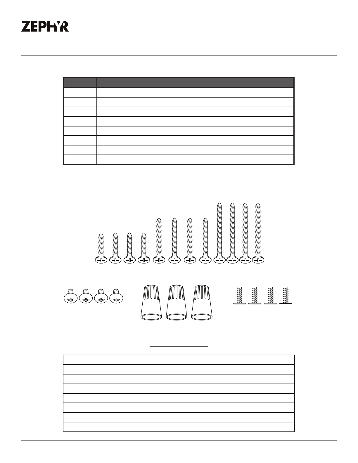
Parts Supplied
Quantity Part
1 Hood
2 Pro bae filters (36" & 42" models)
3 Pro bae filters (48" & 54" models)
2 LumiLight LED (36" & 42" models)
4 LumiLight LED (48" & 54" models)
3 10" round starting collar
2 Top cover plate (for horizontal ducting)
1 Hardware package
M6 x 2” (4)
M6 x 1-1/2” (4)
M6 x 1” (4)
M4 x 8 (4) Wire Caps (3)
Parts Not Supplied
Ducting, conduit and all installation tools
Cable locking connector (if required by local codes)
12" duct cover accessory (36" models) (AK0736BS)
12" duct cover accessory (42" models) (AK0742BS)
12" duct cover accessory (48" models) (AK0748BS)
12" duct cover accessory (52" models) (AK0754BS)
Duct cover extension (Z1C-0178)
Wood board to hang hood (W x D x H)
3/16 x 3/8 (4)
Cypress Use, Care, and Installation Guide
7
Page 7
PRO
Installation Instructions
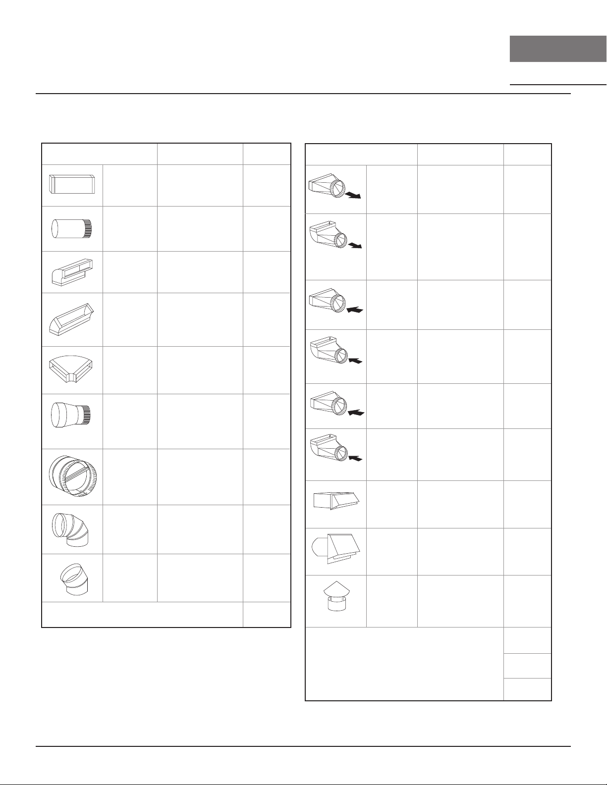
Ducting Calculation Sheet
Duct pieces
3- 1/ 4” x 10”
Rect.,
straight
6”, 7”, 8”, 10”
Round,
straight
3- 1/ 4” x 10”
Rect. 90
elbow
3- 1/ 4” x 10”
Rect. 45
elbow
3- 1/ 4” x 10”
Rect. 90
flat elbow
7” to 6” or
8” to 7” Round
tapered
reducer
6”, 7“, 8”
Round
in-line
damper
6”, 7”, 8”, 10”
Round,
0
90
elbow
6”, 7”, 8”, 10”
Round,
0
45
elbow
Equivalent number
length x used =
1 Ft. x ( ) =
1 Ft. x ( ) =
15 Ft. x ( ) =
0
9 Ft. x ( ) =
0
24 Ft. x ( ) =
0
25 Ft. x ( ) =
15
Ft. x ( ) =
15 Ft.
9 Ft. x ( ) =
Subtotal column 1 =
x ( ) =
To tal
Ft.
Ft.
Ft.
Ft.
Ft.
Ft.
Ft.
Ft.
Ft.
Ft.
Duct pieces
3- 1/ 4” x 10”
Rect. to
6” round
transition
3- 1/ 4” x 10”
Rect. to
6” round
transition
0
elbow
90
6” round to
3- 1/ 4” x 10”
rect.
transition
6” round to
3- 1/ 4” x 10”
rect.
transition
0
90
elbow
7” round to
3 1/ 4” x 10”
rect.
transition
7” round to
3- 1/ 4” x 10”
rect.
transition
0
90
elbow
3- 1/ 4” x 10”
Rect.
wall cap
with damper
6”, 7”, 8”, 10”
Round, wall
cap with
damper
6”, 7”, 8”, 10”
Round
roof cap
Equivalent number
length x used =
5 Ft. x ( ) =
20 Ft. x ( ) =
1 Ft. x ( ) =
16 Ft. x ( ) =
8 Ft. x ( ) =
23 Ft. x ( ) =
30 Ft. x ( ) =
30 Ft. x ( ) =
30 Ft. x ( ) =
CYPRESS
To tal
Ft.
Ft.
Ft.
Ft.
Ft.
Ft.
WALL
Ft.
Ft.
Ft.
8
Maximum Duct Length: For satisfactory air movement,
the total duct length
should not exceed 150 equivalent feet.
Subtotal column 2 =
Subtotal column 1 =
Total ductwork =
Ft.
Ft.
Ft.
Cypress Use, Care, and Installation Guide
Page 8
Installation Instructions
ZEPHYRONLINE.COM
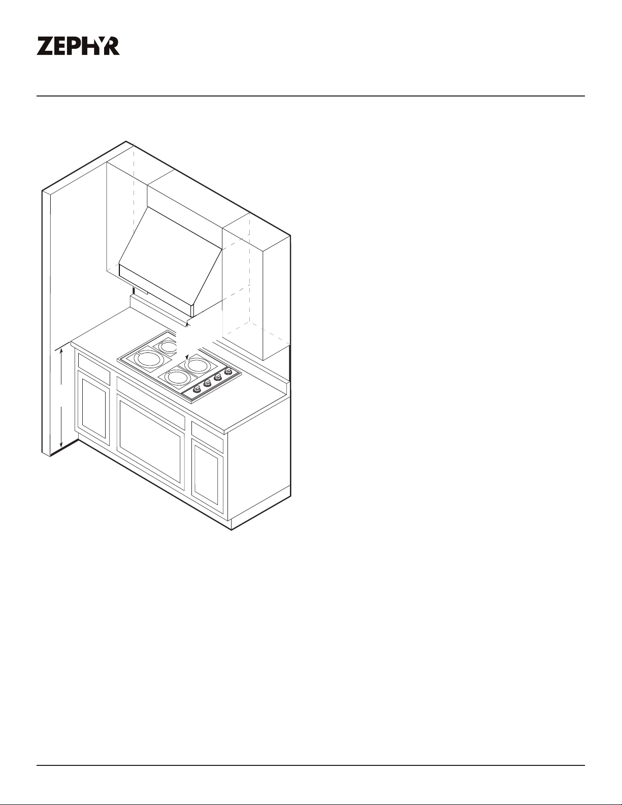
Mounting Height, Clearance, & Ducting
A minimum of 10” round duct is recommended to
maintain maximum air flow eciency.
Always use rigid type metal ducts only. Flexible
ducts could restrict air flow by up to 50%.
Also use the ducting calculation sheet (on page
8) to compute total available duct run when using
elbows, transitions and caps.
ALWAYS, when possible, reduce the number or
transitions and turns. If long duct run is required,
increase duct size.
30” min.
36” max.
36”
If available, also refer range manufacturer’s height clearance requirements and recommended hood
mounting height above range. Always check your local codes for any dierences.
For shipment and installation damages:
If turns or transitions are required; install as far
away from hood duct output and as far apart,
between the two as possible.
Minimum mount height between range top to hood
bottom should be no less than 30”.
Maximum mount height should be no higher than
36”.
It is important to install the hood at the proper
mounting height. Hoods mounted too low could
result in heat damage and fire hazard; while hoods
mounted too high will be hard to reach and will lose
its performance and eciency.
► Please fully inspect unit for damage before installation.
► If the unit is damaged in shipment, return the unit to the store in which it was bought for repair or
replacement.
► If the unit is damaged by the customer, repair or replacement is the responsibility of the customer.
► If the unit is damaged by the installer (if other than the customer), repair of replacement must be
made by arrangement between customer and installer.
Cypress Use, Care, and Installation Guide
9
Page 9
PRO
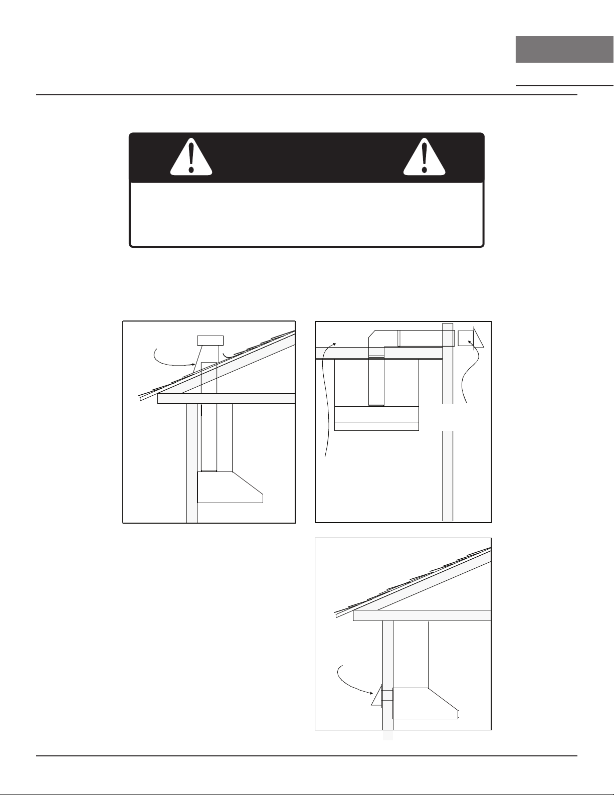
Roof pitch w/
flashing & cap
Sot or crawl space
Side wall cap
w/ gravity damper
Rear ducting
Installation Instructions
CYPRESS
Ducting Options
WARNING
Fire Hazard: NEVER exhaust air or terminate ductwork into
spaces between walls, crawl spaces, ceilings, attics, or garages.
All exhaust must be ducted to the outside, unless using the
recirculating option.
► Use single wall rigid metal ductwork only.
► Fasten all connections with sheet metal screws and tape all joints w/ certified Silver Tape or Duct
Tape.
WALL
10
Cypress Use, Care, and Installation Guide
Page 10

ZEPHYRONLINE.COM
Hood Specications
Installation Instructions
Top View
14-3/16”
6-1/16”
10-3/8”
11-9/16”
Ø 9-15/16”
C/L
35 7/8” (36”)
41 7/8“ (42”)
47 7/8” (48”)
53 7/8” (54”)
Back View
Ducting & Electrical Dimensions
C/L
11-9/16”
1-11/16”
2-5/8”
Ø 9-15/16”
11-9/16”
1-1/16”
1-3/4”
Side View
10-3/8”
4-5/16”
15”
50.5˚
18”
4”
32”
Back View
Mounting Dimensions
3-5/16”
1-11/16”
10-3/8”
14-3/16”
29”
29”
10-3/4”
15”
21-3/4”
16-1/8”
13-5/8”
16-7/8”
5-5/16”
21-1/4”
35-1/4” (42”, 48”, 54”)
Optional Telescopic
Duct Cover
Z1C-0178
Min. - 48”
Max. - 75”
Cypress Use, Care, and Installation Guide
11
Page 11
PRO
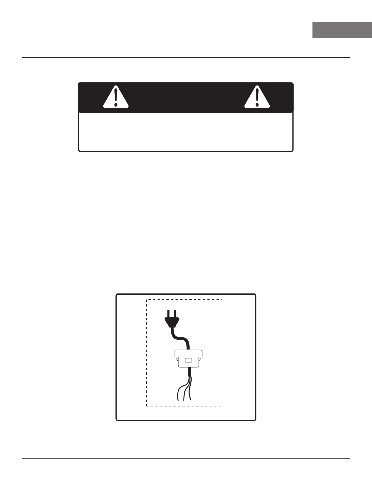
Cable Lock
Installation Instructions
CYPRESS
WALL
Electrical Supply
WARNING
Electrical wiring must be done by qualified person(s) in
accordance with all applicable codes and standards. Turn o
electrical power at service entrance before wiring.
For personal safety, remove house fuse or open circuit breaker before beginning installation. Do not
use extension cord or adapter plug with this appliance.
Follow national electrical codes or prevailing local codes and ordinances.
This appliance requires a 120V 60Hz electrical supply, and connected to an individual, properly
grounded branch circuit, protected by a 15 or 20 ampere circuit breaker or time delay fuse. Wiring
must be 2 wire w/ ground. Please also refer to the Electrical Diagram labeled on product.
Cable Lock
A cable locking connector (not supplied) might be required by local codes. Check with local
requirements and codes, purchase and install appropriate connector if necessary. (FIG. A)
FIG. A
12
Cypress Use, Care, and Installation Guide
Page 12

ZEPHYRONLINE.COM
C/L
C/L
A
B
16-7/8 ”
min
30”
4”
wood board
Mounting the Hood
Installation Instructions
1. Select preferred ducting application (vertical or
horizontal) and prepare hood. Refer to page 14
for horizontal ducting conversion.
2. Plum and mark center line on wall.
3. Choose desired height above cooking surface
(30” min). Level and mark hood bottom, line A
(FIG. B).
4. Level and mark top of wood board, line B (FIG.
B) 16 7/8” from line A.
5. Mark center line of wood board. Center and
align top of board with line B. Secure wood
board to studs using (4) M6 wood screws.
Wood Board Dimensions: (W x D x H)
AK7836CS - 33” x 1/2” x 4”
AK7842CS - 39” x 1/2” x 4”
AK7848CS - 45” x 1/2” x 4”
AK7854CS - 51” x 1/2” x 4”
C/L
B
wood board
4”
16-7/8 ”
A
min
30”
C/L
FIG. B
6. Prepare duct pipe and duct cut outs in upper
cabinet if needed or wall if horizontally ducting
3-5/16”
1-11/16”
hood. Prepare electrical wiring and electrical
cut outs in upper cabinet if needed or wall
if horizontal electrical hook up is required.
Refer to hood specifications on page 11 for
16-1/8”
13-5/8”
dimensions.
7. Mount hood onto wood board and secure using
(4) M6 wood screws.
8. Further secure hood onto wall through lower
21-1/4”
35-1/4” (42”, 48”, 54”)
FIG. C
body screw holes by (2) M6 wood screws. See dimensions in FIG. C.
9. Install electrical. Install duct work and seal with certified aluminum duct tape.
10. Power up hood and check for leaks around duct tape.
11. Install pro bae filters.
16-7/8”
5-5/16”
Cypress Use, Care, and Installation Guide
13
Page 13

PRO
Installation Instructions
CYPRESS
Horizontal Ducting Conversion
This range hood is equipped with a 10" round vertical duct option by default. To convert from 10"
round vertical to 10" round horizontal ducting, please follow the instructions below.
1. Disconnect blower plug.
WALL
A
2. Remove (4) screws from interior
of hood body attaching blower
plate to top of hood body.
Remove blower and blower plate.
3. Knock out plate A for dual blower
horizontal ducting.
14
Cypress Use, Care, and Installation Guide
Page 14

ZEPHYRONLINE.COM
Horizontal Ducting Conversion
Installation Instructions
4. From inside hood body, position
top cover plate to top of hood
body. From outside hood body,
attach top cover plate to top of
hood body using (4) 3/16 x 3/8
screws.
5. Position dual blower plate onto
interior back wall mounting
brackets inside hood body.
Attach by (4) screws previously
removed from step 2. Re-connect
blower plug.
6. Attach 10 inch round blower collar
to back of hood using (4) M4 x 8
screws.
Cypress Use, Care, and Installation Guide
15
Page 15

PRO
Features & Controls
Rotary Controls
OFF
1 Blower On/O/Speed Selection
1
OFF
2
3
1
2
OFF
2 Lights Dim/Bright/O
CYPRESS
WALL
1 Blower On/O/Speed Selection
Rotate dial to change speed levels, (1) for low speed, (2) for medium speed and (3)
for high speed.
2 Lights Dim/Bright/O
Rotate dial to change light settings, (1) for dim light and (2) for bright light.
16
Cypress Use, Care, and Installation Guide
Page 16

Maintenance
ZEPHYRONLINE.COM
Hood & Filter Cleaning
Surface Maintenance
► Do not use corrosive detergents, abrasive detergents or oven cleaners.
► Do not use any product containing chlorine bleach or any product containing chloride.
► Do not use steel wool or abrasive scrubbing pads which will scratch and damage surface.
Cleaning Stainless Steel
Clean periodically with warm soapy water and clean cotton cloth or micro fiber cloth. Always rub
in the direction of the stainless steel grain. To remove heavier grease build up use a liquid degreaser
detergent.
After cleaning use a non-abrasive stainless steel polish/cleaners, to polish and bu out the stainless
luster and grain. Always scrub lightly, with clean cotton cloth or micro fiber cloth and bu in the
direction of the stainless steel grain.
Cleaning the Pro Bae Filters
The stainless steel pro baffle filters are intended to trap residue and grease from cooking. Although
the filters should never need replacing, they are required to be cleaned every 30 days or more often
depending on cooking habits.
Filters may be placed in dishwasher at low heat or soaked in hot soapy water Dry filters and re-install
before using hood.
CAUTION
If this hood is installed in a salt water area (e.g. coast), rinse all
surfaces once a week with clear water even if the hood is not
used. Wipe and dry completely after rinsing.
Cypress Use, Care, and Installation Guide
17
Page 17

PRO
.
1
2
3
Push the clip
Maintenance
Removing Pro Bae Filters, FIG. D
1. Push filter away from front of range hood using handles.
2. Pivot front of filter downward.
3. Remove filter by pulling away from hood.
Replacing Pro Bae Filters
Hood Model Part Number Qty. to Order
AK7836CS 50210031 2
AK7842CS 50210031 2
AK7848CS 50210031 3
AK7854CS 50210031 3
CYPRESS
WALL
FIG. D
LumiLight LED
In the unlikely event that your LumiLight LED fails, please contact Zephyr to order replacement parts.
See the list of parts and accessories page for part numbers and contact information.
LED Removal, FIG. E
1. Remove grease filters.
2. (If applicable) remove both side spacer panels
for each spacer panel.
3. Remove screws on light panel.
4. Disconnect LED light quick connector.
5. Push in the two side clips on the ends of the
LED light.
6. Push LED light through the light panel opening.
18
FIG. E
Cypress Use, Care, and Installation Guide
Page 18

ZEPHYRONLINE.COM
Wiring Diagram
AK7836CS, AK7842CS,
AK7848CS, AK7854CS
Wiring Diagram
Motor
Green
Body
Green
Body
Motor
Red
Red
White
White
Volts Hz
Max Amps
120 60 Dual Motor 9
Yellow
Brown
Grey
Blue
Brown
Grey
Blue
Yellow
Grey
Brown
Blue
White
Red
Black
Body
Green
Black
B/W
White
B/W
REMARKS: CONDENSER 22uF / 250VAC 2PCS FIT AC120V 60Hz
B/W
For 48” and 54”
models only
Cypress Use, Care, and Installation Guide
19
Page 19

PRO
Troubleshooting
Possible Problem Possible Cause Solutions
After installation, the
unit doesn’t work.
Light works, but
blower is not turning.
The power source is not turned
ON.
The power line and the cable
locking connector is not
connecting properly.
The switch board wirings are
disconnected.
The switch board is defective. Change the switch board.
The blower wire is not connected. Make sure the blower wire is plugged
The thermally protected system
detects if the blower is too hot
to operate and shuts the blower
down.
Damaged capacitor. Change the capacitor.
Make sure the circuit breaker and the
unit’s power is ON.
Check the power connection with the
unit is connected properly.
Make sure the wirings at the switch
board are connected properly.
into the molex connector.
The blower will function properly after
the thermally protected system cool
down.
CYPRESS
WALL
The blower is defective, possibly
seized.
The unit is vibrating. The blower is not secured in place. Tighten the blower in place.
Damaged blower wheel. Replace the blower.
The hood is not secured in place. Check the installation of the hood.
The unit is whistling. A filter is not in the correct
position.
The duct pipe connections are not
sealed or connected properly.
The blower is working,
but the LumiLight
LEDs are not.
The LumiLight LED connector is
disconnected.
Defective LumiLight LED. Change the LumiLight LED.
The switch board is defective. Change the switch board.
Change the blower.
Adjust the filters until the whistling stops.
Check the duct pipe connections to be
sure all connections are sealed properly.
Connect the LumiLight LED connector.
20
Cypress Use, Care, and Installation Guide
Page 20

Troubleshooting
ZEPHYRONLINE.COM
Possible Problem Possible Cause Solutions
The hood is not
venting out properly.
Filter is vibrating. Filter is loose. Adjust or change the filter.
Using the wrong size of ducting. Change the ducting to the correct size.
The hood might be hanging to
high from the cook top.
The wind from the opened
windows or opened doors in the
surrounding area are aecting
the ventilation of the hood.
Blockage in the duct opening or
ductwork.
Spring clip is broken on the filter. Change the spring clip.
Adjust the distance between the cook
top and the bottom of the hood within
30” and 36” range.
Close all the windows and doors to
eliminate the outside wind flow.
Remove all the blocking from the duct
work or duct opening.
Cypress Use, Care, and Installation Guide
21
Page 21

PRO
List of Parts & Accessories
Description Part Number
Replacement Parts
LumiLight LED, 6W Z0B0050
Pro Bae Filter (each) 50210031
Optional Accessories
12" Duct Cover (36") AK0736BS
12" Duct Cover (42") AK0742BS
12" Duct Cover (48") AK0748BS
12" Duct Cover (54") AK0754BS
Duct Cover Extension
(10' - 12' ceilings)
To order parts, visit us online at http://store.zephyronline.com.
Z1C-0178
CYPRESS
WALL
22
Cypress Use, Care, and Installation Guide
Page 22

Limited Warranty
Zephyr, 2277 Harbor Bay Parkway, Alameda, CA 94502
Limited Warranty
ZEPHYRONLINE.COM
TO OBTAIN SERVICE UNDER WARRANTY OR FOR ANY SERVICE RELATED QUESTIONS
United States Customers please call: 1-888-880-8368 or contact us at: zephyronline.com/contact
Canada Customers please call: 1-800-361-0799 or Email: service@distinctive-online.com
Zephyr Ventilation, LLC (referred to herein as “we” or “us”) warrants to the original consumer purchaser (referred to herein
as “you” or “your”) of Zephyr products (the “Products”) that such Products will be free from defects in materials or
workmanship as follows:
Three Year Limited Warranty for Parts: For three years from the date of your original purchase of the Products, we will
provide, free of charge, Products or parts (including LED light bulbs, if applicable) to replace those that failed due to
manufacturing defects subject to the exclusions and limitations below. We may choose, in our sole discretion, to repair or
replace parts before we elect to replace the Products.
One Year Limited Warranty for Labor: For one
provide, free of charge, the labor cost associated with repairing the Products or parts to replace those that failed due to
manufacturing defects subject to the exclusions and limitations below. After the first year from the date of your original
purchase, you are responsible for all labor costs associated with this warranty.
Warranty Exclusions: This warranty covers only repair or replacement, at our option, of defective Products or parts and
does not cover any other costs related to the Products including but not limited to: (a) normal maintenance and service
required for the Products and consumable parts such as fluorescent, incandescent or halogen light bulbs, mesh and charcoal filters and fuses; (b) any Products or
faulty installation or installation contrary to recommended installation instructions, improper maintenance or repair (other
than by us); (c) commercial or government use of the Products or use otherwise inconsistent with its intended purpose; (d)
natural wear of the finish of the Products or wear caused by improper maintenance, use of corrosive and abrasive cleaning
products, pads, and oven cleaner products; (e) chips, dents or cracks caused by abuse or misuse of the Products; (f) service
trips to your home to teach you how to use the Products; (g) damage to the Products caused by accident, fire, floods, acts
of God; or (h) Custom installations or alterations that impact serviceability of the Products. If you are outside our service
area, additional charges may apply for shipping costs for
travel cost to have a service technician come to your home to repair, remove or reinstall the Products. After the first year
from the date of your original purchase, you are also responsible for all labor costs associated with this warranty. All Products
must be installed by a qualified professional installer to be eligible for warranty repairs or service.
Limitations of Warranty. OUR OBLIGATION TO REPAIR OR REPLACE, AT OUR OPTION, SHALL BE YOUR SOLE
AND EXCLUSIVE REMEDY UNDER THIS WARRANTY. WE SHALL NOT BE LIABLE FOR INCIDENTAL,
CONSEQUENTIAL OR SPECIAL DAMAGES ARISING OUT OF OR IN CONNECTION WITH THE USE OR
PERFORMANCE OF THE PRODUCTS. THE EXPRESS WARRANTIES IN THE PRECEDING SECTION ARE
EXCLUSIVE AND IN LIEU OF ALL OTHER EXPRE
OTHER EXPRESS WARRANTIES FOR THE PRODUCTS, AND DISCLAIM AND EXCLUDE ALL WARRANTIES
IMPLIED BY LAW, INCLUDING THOSE OF MERCHANTABILITY AND FITNESS FOR A PARTICULAR PURPOSE.
Some states or provinces do not allow limitations on the duration of an implied warranty or the exclusion or limitation of
incidental or consequential damages, so the above limitations or exclusions may not apply to you. To the extent that
applicable law prohibits the exclusion of implied warranties, the duration of any applicable implied warranty is limited to the
same three-year and one-year periods described above if permitted by applicable law. Any oral or written description of the
Products is for the sole purpose of identifying the Products and shall not be construed as an express warr
using, implementing or permitting use of the Products, you shall determine the suitability of the Products for the intended
use, and you shall assume all risk and liability whatsoever in connection with such determination. We reserve the right to
use functionally equivalent refurbished or reconditioned parts or Products as warranty replacements or as part of warranty
service. This warranty is not transferable from the original purchaser and only applies to the consumer residence where the
Product was originally installed located in the United States and Canada. This warranty is not extended to resellers.
To Obtain Service Under Limited Warranty: To qualify for warranty service, you must: (a) notify us at the address or
telephone number stated below within 60 days of the discovery of the defect; (b) give the model number and serial
and (c) describe the nature of any defect in the Product or part. At the time of the request for warranty service, you must
present evidence of your proof of purchase and proof of the original purchase date. If we determine that the warranty
exclusions listed above apply or if you fail to provide the necessary documentation to obtain service, you will be responsible
for all shipping, travel, labor and other costs related to the services. This warranty is not extended or restarted upon warranty
repair or replacements.
Please check our website for any additional Product information, www.zephyronline.com
y
ear from the date of your original purchase of the Products, we will
parts which have been subject to freight damage, misuse, negligence, accident,
warranty repair at our designated service locations and for the
WARRANTIES. WE HEREBY DISCLAIM AND EXCLUDE ALL
SS
nty. Prior to
a
number;
Cypress Use, Care, and Installation Guide
23
Page 23

PRO
Product Registration
Congratulations on the purchase of your
Zephyr product! Please take a moment to
register your new Zephyr product at
www.zephyronline.com/registration
IT’S IMPORTANT
Prompt registration helps in more ways
than one.
Ensures warranty coverage should you need
service.
Ownership verification for insurance purposes.
Notification of product changes or recalls.
CYPRESS
WALL
Zephyr Ventilation | 2277 Harbor Bay Pkwy. | Alameda, CA 94502 | 1.888.880.8368
24
Cypress Use, Care, and Installation Guide
Page 24

WWW.ZEPHYRONLINE.COM
Cypress
AK7836CS, AK7842CS, AK7848CS, AK7854CS
EN Use, Care, and Installation Guide
FR Guide d’utilisation, d’entretien et d’installation
FEB22.0101
DESTINÉ À L’EXTÉRIEUR PATIO COUVERT OU ZONE LANAI
Page 25

ZEPHYRONLINE.COM
Consignes de sécurité ....................................................................... 4-6
Types d’avertissements de sécurité ..................................................... 4
Sécurité générale ...............................................................................4-5
Opération ........................................................................................... 6
Exigences électriques ......................................................................... 6
Liste de matériel .................................................................................. 7
Instructions d’installation ..................................................................8-15
Feuille de calcul pour le conduit d’aération ......................................... 8
Hauteur de montage, dégagement et gaine ....................................... 9
Options de conduits ...........................................................................10
Spécifications de la hotte ...................................................................11
Fourniture électrique ..........................................................................12
Raccord de câble ...............................................................................12
Montage de la hotte ...........................................................................13
Conversion de conduit horizontal .................................................... 14-15
Fonctionnalités et commandes ......................................................... 16
Commandes rotatives ........................................................................16
Entretien ........................................................................................... 17-18
Nettoyage de la hotte et du filtre ........................................................17
LumiLight LED ....................................................................................18
Schéma de câblage ............................................................................ 19
Dépannage ......................................................................................20-21
Liste des pièces et accessoires ........................................................... 22
Garantie limitée .................................................................................23
Enregistrement du produit .................................................................. 24
Table des matières
Page
Cypress Guide d’utilisation, d’entretien et d’installation
3
Page 26

PRO
Consignes de sécurité
LISEZ ET CONSERVEZ CES INSTRUCTIONS
Votre sécurité et celle des gens qui vous entourent sont très
importantes.
Ce manuel contient de nombreux messages de sécurité relatifs
à votre appareil. Lisez tous les messages et conformez-vous-y
en tout temps.
Voici le symbole d’alerte à la sécurité. Ce symbole vous informe
de possibles dangers qui pourraient entraîner de graves lésions
corporelles ou la mort. Tous les messages de sécurité suivent
le symbole d’alerte à la sécurité et comportent les mots «
DANGER », « AVERTISSEMENT » ou « ATTENTION ».
DANGER
Le mot « danger » signifie que le fait de ne pas tenir compte
de l’énoncé de sécurité peut entraîner une blessure grave ou
la mort.
AVERTISSEMENT
CYPRESS
MUR
AVERTISSEMENT
AVERTISSEMENT - POUR RÉDUIRE LES RISQUES D’INCENDIE,
DE CHOC ÉLECTRIQUE OU DE BLESSURES AUX PERSONNES,
RESPECTEZ LES SUIVANTS:
a) N’utilisez cet appareil que de la manière prévue par le
fabricant. Si vous avez des questions, contactez le fabricant.
b) Avant l’entretien ou le nettoyage de l’unité, coupez
l’alimentation au panneau de service et verrouillez les moyens
de déconnexion de service pour éviter toute mise sous tension
accidentelle. Lorsque le moyen de déconnexion de service
ne peut pas être verrouillé, fixez solidement un dispositif
d’avertissement bien visible, tel qu’une étiquette, au panneau
de service.
ATTENTION
Pour Une Ventilation Générale Uniquement. Ne Pas Utiliser
Pour Évacuer Des Matières Et Des Vapeurs Dangereuses Ou
Explosives. Soyez prudent lorsque vous utilisez des produits
de nettoyage pour détergents. Convient pour une utilisation
dans la zone de cuisson domestique.
Le mot « avertissement » signifie que le fait de ne pas
tenir compte de l’énoncé de sécurité peut entraîner des
dommages importants au produit, une lésion corporelle
grave ou la mort.
ATTENTION
Le mot « attention » signifie que le fait de ne pas tenir
compte de l’énoncé de sécurité peut entraîner une lésion
corporelle mineure ou modérée, ou encore des dommages
au produit ou à la propriété.
Sécurité générale
ATTENTION
Pour réduire le risque d’incendie ou de choc électrique,
n’utilisez pas ce ventilateur avec un dispositif de commande
à semi-conducteurs.
AVERTISSEMENT
AVERTISSEMENT - POUR RÉDUIRE LE RISQUE D’INCENDIE DE
GRAISSE SUR LE HAUT DE CUISINIÈRE:
a) Ne laissez jamais les unités de surface sans surveillance
à des réglages élevés. Les débordements provoquent de la
fumée et des débordements graisseux qui peuvent s’enflammer.
Chauer les huiles lentement à des réglages faibles ou
moyens.
b) Allumez toujours la hotte lorsque vous cuisinez à feu vif
ou lorsque vous flambez des aliments. (c’est-à-dire Crêpes
Suzette, Cerises Jubilee, Boeuf au Poivre Flambé »).
c) Nettoyez fréquemment les ventilateurs de ventilation. La
graisse ne doit pas s’accumuler sur le ventilateur ou le filtre.
d) Utilisez une taille de casserole appropriée. Utilisez toujours
des ustensiles de cuisine adaptés à la taille de l’élément de
surface.
4
Cypress Guide d’utilisation, d’entretien et d’installation
Page 27

ZEPHYRONLINE.COM
Consignes de sécurité
LISEZ ET CONSERVEZ CES INSTRUCTIONS
AVERTISSEMENT
AVERTISSEMENT - POUR RÉDUIRE LE RISQUE DE BLESSURE
DES PERSONNES EN CAS D’INCENDIE DE GRAISSE SUR LE
HAUT DE LA CUISINIÈRE, RESPECTEZ CE QUI SUIT:
a) DES FLAMMES PLUS INTELLIGENTES avec un couvercle bien
ajusté, une plaque à biscuits ou un plateau en métal, puis
éteignez le brûleur. FAITES ATTENTION À ÉVITER LES BRÛLURES.
Si les flammes ne s’éteignent pas immédiatement, ÉVACUER ET
APPELER LE DÉPARTEMENT DES INCENDIES.
b) NE JAMAIS RAMASSER UNE PLAQUE ENFLAMME - Vous
pourriez être brûlé.
c) N’UTILISEZ PAS D’EAU, ni de torchons ou de serviettes
humides - une violente explosion de vapeur en résultera.
d) Utilisez un extincteur UNIQUEMENT si:
1) Vous savez que vous possédez un extincteur de classe
ABC et vous savez déjà comment l’utiliser.
2) Le feu est petit et contenu dans la zone où il a
commencé.
3) Le service d’incendie est appelé.
4) Vous pouvez combattre le feu dos à une sortie
Basé sur “Kitchen Firesafety Tips” publié par la NFPA.
AVERTISSEMENT
AVERTISSEMENT
AVERTISSEMENT - POUR RÉDUIRE LES RISQUES D’INCENDIE,
DE DÉCHARGE ÉLECTRIQUE OU DE BLESSURES AUX
PERSONNES, RESPECTEZ CE QUI SUIT:
a) Les travaux d’installation et le câblage électrique doivent
être eectués par des personnes qualifiées conformément à
tous les codes et normes applicables, y compris la construction
résistant au feu.
b) Une quantité d’air susante est nécessaire pour une
combustion et une évacuation correctes des gaz par le conduit
de fumée (cheminée) de l’équipement à combustible pour
empêcher le refoulement. Suivez les directives et les normes
de sécurité du fabricant de l’équipement de chauage, telles
que celles publiées par la National Fire Protection Association
(NFPA), l’American Society for Heating, Refrigeration and Air
Conditioning Engineers (ASHRAE) et les autorités locales du
code.
c) Lorsque vous coupez ou percez dans un mur ou un plafond,
n’endommagez pas le câblage électrique et les autres services
publics cachés.
d) Les ventilateurs à conduit doivent toujours être ventilés vers
l’extérieur.
e) Si cet appareil doit être installé au-dessus d’une baignoire
ou d’une douche, il doit être marqué comme approprié pour
l’application et être connecté à un circuit de dérivation protégé
par un disjoncteur de fuite à la terre (GFCI).
AVERTISSEMENT
POUR RÉDUIRE LES RISQUES D’INCENDIE, UTILISEZ
UNIQUEMENT DES CONDUITS MÉTALLIQUES.
ATTENTION
Pour réduire les risques d’incendie et pour évacuer
correctement l’air extérieur, ne pas évacuer l’air évacué dans
les espaces à l’intérieur des murs, plafonds, greniers, vides
sanitaires ou garages.
Prop. 65 Avertissement pour les résidents de Californie: Ce
produit peut contenir des produits chimiques reconnus par
l’État de Californie comme pouvant provoquer le cancer,
des malformations congénitales ou d’autres troubles de la
Cypress Guide d’utilisation, d’entretien et d’installation
AVERTISSEMENT
reproduction.
5
Page 28

PRO
Consignes de sécurité
CYPRESS
LISEZ ET CONSERVEZ CES INSTRUCTIONS
Opération
► Laissez toujours les grilles de sécurité et les filtres en place. Sans ces composants, les souantes en fonctionnement pourraient
s’accrocher aux cheveux, aux doigts et aux vêtements amples.
► Le fabricant décline toute responsabilité en cas de non-respect des instructions données ici pour l’installation, la maintenance et
l’utilisation appropriée du produit. Le fabricant décline en outre toute responsabilité en cas de blessure due à une négligence et la
garantie de l’unité expire automatiquement en raison d’un mauvais entretien.
REMARQUE: veuillez consulter www.zephyronline.com pour les révisions avant d’eectuer tout travail personnalisé.
Exigences électriques
Important:
► Respectez tous les codes et ordonnances en vigueur.
► Il est de la responsabilité du client d’en prendre connaissance ci-dessous:
► Pour contacter un installateur électrique qualifié.
► Pour garantir que l’installation électrique est adéquate et conforme au National Electrical Code, ANSI / NFPA 70 dernière édition *
ou aux normes CSA C22.1-94, Code canadien de l’électricité, partie 1 et C22.2 No.0-M91 - dernière édition ** et tous les codes et
ordonnances locaux.
► Si les codes le permettent et qu’un fil de terre séparé est utilisé, il est recommandé qu’un électricien qualifié détermine que le
chemin de terre est adéquat.
► Ne pas mettre à la terre un tuyau de gaz.
► Vérifiez auprès d’un électricien qualifié si vous n’êtes pas sûr que la hotte est correctement mise à la terre.
► Ne pas avoir de fusible dans le circuit neutre ou de terre.
► Cet appareil nécessite une alimentation électrique de 120 V à 60 Hz et est connecté à un circuit de dérivation individuel
correctement mis à la terre protégé par un disjoncteur de 15 ou 20 ampères ou un fusible temporisé. Le câblage doit être à 2 fils
avec mise à la terre. Veuillez également vous référer au schéma électrique du produit.
► Un connecteur de verrouillage de câble (non fourni) peut également être requis par les codes locaux. Vérifiez les exigences locales,
achetez et installez le connecteur approprié si nécessaire.
* National Fire Protection Association Batterymarch Park, Quincy, Massachusetts 02269
** CSA International 8501 East Pleasant Valley Road, Cleveland, Ohio 44131-5575
MUR
► Destiné à un patio extérieur couvert ou à une véranda.
► Convient pour une utilisation dans des endroits humides lorsqu’il est installé dans un circuit de dérivation protégé par GFCI.
6
Cypress Guide d’utilisation, d’entretien et d’installation
Page 29

ZEPHYRONLINE.COM
Liste de matériel
Pièces fournies
Quantité Partie
1 Hotte
2 Filtres déflecteurs pro (modèles 36 po et 42 po)
3 Filtres déflecteurs pro (modèles 48 po et 54 po)
2 LumiLight LED (modèles 36 po et 42 po)
4 LumiLight LED (modèles 48 po et 54 po)
3 Collier de départ rond de 10”
2 Plaque de couverture supérieure (pour conduit horizontal)
1 Pack matériel
M6 x 2” (4)
M6 x 1-1/2” (4)
M6 x 1” (4)
M4 x 8 (4) Wire Caps (3)
Pièces non fournies
Conduits, conduits et tous les outils d’installation
Raccord de câble (si requis par les codes locaux)
Accessoire cache-conduit 12 po (modèles 36 po) (AK0736BS)
Accessoire cache-conduit 12 po (modèles 42 po) (AK0742BS)
Accessoire cache-conduit 12 po (modèles 48 po) (AK0748BS)
Accessoire cache-conduit 12 po (modèles 52 po) (AK0754BS)
Rallonge de cache-conduit (Z1C-0178)
Planche en bois pour accrocher la hotte (L x P x H)
3/16 x 3/8 (4)
Cypress Guide d’utilisation, d’entretien et d’installation
7
Page 30

PRO
Instructions d’installation
Feuille de calcul pour le conduit d’aération
Pièces de conduit
3- 1/ 4” x 10”
rect., droit
6”, 7”, 8”, 10”
circ., droit
3- 1/ 4” x 10”
rect.,
coude à 90º
3- 1/ 4” x 10”
rect.,
coude à 45º
3- 1/ 4” x 10”
rect.,
coude plat
à 90º
7” to 6” or
8” to 7” circ.
reducteur
conique
6”, 7“, 8”
circ.
bouchone de
l’air
6”, 7”, 8”, 10”
circ.,
coude à 90º
6”, 7”, 8”, 10”
coude à 45º
Longueur x
Nombre utilisé
1 pi x ( ) =
1 pi x ( ) =
15 pi x ( ) =
9 pi x ( ) =
24 pi x ( ) =
25 pi x ( ) =
15
pi x ( ) =
15 pi
9 pi x ( ) =
=
x ( ) =
Sous-total - colonne 1=
To tal
pi
pi
pi
pi
pi
pi
pi
pi
pi
pi
Pièces de conduit
6” circ. à
rect. de
3-1/4" x 10"
6” circ. à
rect. de
3-1/4" x 10",
coude à 90º
6” circ. à
rect. de
3-1/4" x 10"
6” circ. à
rect. de
3-1/4" x 10",
coude à 90º
7” circ. à
rect. de
3-1/4" x 10"
7” circ. à
rect. de
3-1/4" x 10",
coude à 90º
3-1/ 4” x 10”
embout mural
rect./registre
6”, 7”, 8”, 10”
embout
mural
circ./registre
6”, 7”, 8”, 10”
chapeau de
toiture circ.
Longueur x
Nombre utilisé
5 pi x ( ) =
20 pi x ( ) =
1 pi x ( ) =
16 pi x ( ) =
8 pi x ( ) =
23 pi x ( ) =
30 pi x ( ) =
30 pi x ( ) =
30 pi x ( ) =
=
CYPRESS
To tal
pi
pi
pi
pi
pi
pi
pi
pi
pi
MUR
Longueur maximale du conduit d’aération :
Pour un mouvement d’air convenable, la longueur totale d’un conduit
d’aération ne devrait pas compter plus que l’équivalent de 150 pieds.
8
Cypress Guide d’utilisation, d’entretien et d’installation
Sous-total - colonne 2 =
Sous-total - colonne 1 =
Total du conduit =
pi
pi
pi
Page 31

Instructions d’installation
ZEPHYRONLINE.COM
Hauteur de montage, dégagement et gaine
Un conduit rond d’au moins 10 po est recommandé pour
maintenir une ecacité maximale du débit d’air.
Utilisez toujours uniquement des conduits métalliques de
type rigide. Les conduits flexibles peuvent restreindre le
débit d’air jusqu’à 50%.
Utilisez également la feuille de calcul des gaines (à la
page 8) pour calculer la longueur totale des gaines
disponibles lorsque vous utilisez des coudes, des
transitions et des capuchons.
TOUJOURS, lorsque cela est possible, réduire le nombre
30 po min.
36 po max.
de transitions et de virages. Si un long trajet de conduit
est requis, augmentez la taille du conduit.
Si des virages ou des transitions sont nécessaires;
36 po
de montage. Les hottes montées trop bas peuvent entraîner des dommages causés par la chaleur et
un risque d’incendie; tandis que les hottes montées trop haut seront diciles à atteindre et perdront
leurs performances et leur ecacité.
Si disponible, reportez-vous également aux exigences de dégagement en hauteur du fabricant de la
cuisinière et à la hauteur de montage recommandée de la hotte au-dessus de la cuisinière. Vérifiez
toujours vos codes locaux pour toute diérence
Pour les dommages liés à l’expédition et à l’installation:
► Veuillez inspecter complètement l’unité pour déceler tout dommage avant l’installation.
installer aussi loin que possible de la sortie du conduit de
la hotte et aussi loin que possible entre les deux.
La hauteur minimale de montage entre le haut de la
cuisinière et le bas de la hotte ne doit pas être inférieure
à 30 po. La hauteur de montage maximale ne doit pas
dépasser 36 po.
Il est important d’installer la hotte à la bonne hauteur
► Si l’appareil est endommagé lors de l’expédition, renvoyez-le au magasin où il a été acheté pour
réparation ou remplacement.
► Si l’appareil est endommagé par le client, la réparation ou le remplacement est à la charge du
client.
► Si l’unité est endommagée par l’installateur (si autre que le client), la réparation du remplacement
doit être eectuée par arrangement entre le client et l’installateur.
Cypress Guide d’utilisation, d’entretien et d’installation
9
Page 32

PRO
Pente de toit avec
solin et chapeau
Sous-face ou vide sanitaire
Capuchon de paroi
latérale avec
amortisseur de
gravité
Conduit arrière
Instructions d’installation
CYPRESS
Options de conduits
ATTENTION
Risque d’incendie: NE JAMAIS évacuer l’air ni terminer de
conduits dans des espaces entre les murs, les vides sanitaires,
les plafonds, les greniers ou les garages. Tout l’échappement
doit être canalisé vers l’extérieur, à moins d’utiliser l’option de
recirculation.
► Utilisez uniquement des conduits métalliques rigides à paroi simple.
► Fixez toutes les connexions avec des vis à tôle et collez tous les joints avec du ruban argenté ou du
ruban adhésif.
MUR
10
Cypress Guide d’utilisation, d’entretien et d’installation
Page 33

ZEPHYRONLINE.COM
Vue de dessus
Vue de côté
Vue arrière
Conduits et dimensions électriques
15 po
32 po
4 po
18 po
11-9/16 po
1-3/4 po
1-1/16 po
11-9/16 po
6-1/16 po
10-3/8 po
14-3/16 po
2-5/8 po
Ø 9-15/16 po
10-3/8 po
4-5/16 po
11-9/16 po
10-3/4 po
10-3/8 po
14-3/16 po
Ø 9-15/16 po
1-11/16 po
35 7/8 po (36 po)
41 7/8 po (42 po)
47 7/8 po (48 po)
53 7/8 po (54 po)
C/L
C/L
Vue arrière
Cotes de montage
16-7/8 po
16-1/8 po
13-5/8 po
1-11/16 po
3-5/16 po
21-1/4 po
35-1/4 po (42 po, 48 po, 54 po)
5-5/16 po
50.5˚
Télescopique en option
Couverture de conduit
Z1C-0178
Min. - 48 po
Max. - 75 po
29 po
15 po
21-3/4 po
29 po
Spécications de la hotte
Instructions d’installation
Cypress Guide d’utilisation, d’entretien et d’installation
11
Page 34

PRO
Raccord de câble
Instructions d’installation
CYPRESS
Fourniture électrique
ATTENTION
Le câblage électrique doit être eectué par des personnes
qualifiées conformément à tous les codes et normes applicables.
Cette hotte doit être correctement mise à la terre. Coupez
l’alimentation électrique à l’entrée de service avant le câblage.
Pour votre sécurité personnelle, retirez le fusible de la maison ou ouvrez le disjoncteur avant de
commencer l’installation. N’utilisez pas de rallonge ni de fiche d’adaptateur avec cet appareil.
Suivez les codes électriques nationaux ou les codes et règlements locaux en vigueur.
Cet appareil nécessite une alimentation électrique de 120 V 60 Hz et est connecté à un circuit de
dérivation individuel correctement mis à la terre, protégé par un disjoncteur de 15 ou 20 ampères
ou un fusible temporisé. Le câblage doit être à 2 fils avec terre. Veuillez également vous référer au
schéma électrique étiqueté sur le produit.
MUR
Raccord de câble
Un connecteur de verrouillage de câble (non fourni) peut être requis par les codes locaux. Vérifiez les
exigences et les codes locaux, achetez et installez le connecteur approprié si nécessaire. (FIG. A)
FIG. A
12
Cypress Guide d’utilisation, d’entretien et d’installation
Page 35

ZEPHYRONLINE.COM
C/L
C/L
A
B
16-7/8 po
min
30 po
4 po
planche de bois
Montage de la hotte
Instructions d’installation
1. Sélectionnez l’application de conduit préférée
(verticale ou horizontale) et préparez la hotte.
Reportez-vous à la page 14 pour la conversion
des conduits horizontaux.
2. Prune et marque la ligne médiane sur le mur.
3. Choisissez la hauteur désirée au-dessus de
la surface de cuisson (30 po min). Nivelez et
marquez le bas de la hotte, ligne A (FIG. B).
4. Nivelez et marquez le haut de la planche de
bois, ligne B (FIG. B) à 16 7/8 po de la ligne A.
5. Marquez la ligne médiane de la planche de
bois. Centrez et alignez le haut de la planche
avec la ligne B. Fixez la planche de bois
aux montants à l’aide de (4) vis à bois M6.
Dimensions de la planche de bois : (L x P x H)
AK7836CS - 33 po x 1/2 po x 4 po
AK7842CS - 39 po x 1/2 po x 4 po
AK7848CS - 45 po x 1/2 po x 4 po
AK7854CS - 51 po x 1/2 po x 4 po
6. Préparez le tuyau de conduit et les découpes
de conduit dans l’armoire supérieure si
nécessaire ou dans le mur si la hotte est
canalisée horizontalement.
7. Préparez le câblage électrique et les découpes
électriques dans l’armoire supérieure si
nécessaire ou dans le mur si un raccordement
électrique horizontal est requis. Reportez-vous
aux spécifications de la hotte à la page 11 pour
les dimensions.
1-11/16 po
16-1/8 po
13-5/8 po
B
A
3-5/16 po
C/L
planche de bois
C/L
FIG. B
21-1/4 po
35-1/4 po (42 po, 48 po, 54 po)
FIG. C
4 po
16-7/8 po
min
30 po
16-7/8 po
5-5/16 po
8. Montez la hotte sur la planche de bois et fixez-la à l’aide de (4) vis à bois M6.
9. Fixez davantage la hotte au mur à travers les trous de vis du corps inférieur à l’aide de (2) vis à
bois M6. Voir les dimensions sur la FIG. C
10. Installer électrique. Installez les conduits et scellez-les avec du ruban adhésif en aluminium certifié.
Allumez la hotte et vérifiez s’il y a des fuites autour du ruban adhésif.
11. Installez des filtres déflecteurs pro.
Cypress Guide d’utilisation, d’entretien et d’installation
13
Page 36

PRO
Instructions d’installation
CYPRESS
Conversion de conduits horizontaux
Cette hotte est équipée par défaut d’une option de conduit vertical rond de 10”. Pour convertir un
conduit vertical rond de 10” en conduit horizontal rond de 10”, veuillez suivre les instructions cidessous.
1. Débranchez la prise du
ventilateur.
MUR
A
2. Retirez les (4) vis de l’intérieur du
corps de la hotte fixant la plaque
du ventilateur au haut du corps
de la hotte. Retirez le ventilateur
et la plaque du ventilateur.
3. Plaque défonçable A pour les
conduits horizontaux à double
souante.
14
Cypress Guide d’utilisation, d’entretien et d’installation
Page 37

Instructions d’installation
ZEPHYRONLINE.COM
Conversion de conduits horizontaux
4. Depuis l’intérieur du corps de
5. Positionnez la plaque du
la hotte, placez la plaque de
couverture supérieure sur le
dessus du corps de la hotte.
Depuis l’extérieur du corps
de la hotte, fixez la plaque de
couverture supérieure au haut du
corps de la hotte à l’aide de (4)
vis 3/16 x 3/8.
ventilateur double sur les
supports de montage du mur
arrière intérieur à l’intérieur du
corps de la hotte. Fixez à l’aide
des (4) vis précédemment retirées
à l’étape 2. Rebranchez la fiche
du ventilateur.
6. Fixez le collier de ventilateur rond
de 10 pouces à l’arrière de la
hotte à l’aide de (4) vis M4 x 8.
Cypress Guide d’utilisation, d’entretien et d’installation
15
Page 38

PRO
Fonctionnalités et commandes
Commandes rotatives
1 Ventilateur Marche/Arrêt/Sélection de vitesse
OFF
1
2
3
OFF
1
2
OFF
2 Lumières tamisées/lumineuses/éteintes
CYPRESS
MUR
1 Ventilateur Marche/Arrêt/Sélection de vitesse
Tournez le cadran pour changer les niveaux de vitesse, (1) pour une vitesse faible, (2)
pour une vitesse moyenne et (3) pour une vitesse élevée.
2 Lumières tamisées/lumineuses/éteintes
Tournez le cadran pour modifier les paramètres d'éclairage, (1) pour une lumière faible
et (2) pour une lumière vive.
16
Cypress Guide d’utilisation, d’entretien et d’installation
Page 39

Entretien
ZEPHYRONLINE.COM
Nettoyage de la hotte et du ltre
Entretien de surface
► N’utilisez pas de détergents corrosifs, de détergents abrasifs ou de nettoyants pour four.
► N’utilisez aucun produit contenant un agent de blanchiment chloré ou un produit contenant du
chlorure.
► N’utilisez pas de laine d’acier ou de tampons à récurer abrasifs qui pourraient rayer et
endommager la surface.
Nettoyage de l’acier inoxydable
Nettoyez périodiquement avec de l’eau chaude savonneuse et un chion en coton propre ou un
chion en microfibres. Frottez toujours dans le sens du grain de l’acier inoxydable. Pour éliminer les
accumulations de graisse plus lourdes, utilisez un détergent dégraissant liquide.
Après le nettoyage, utilisez un produit de polissage / nettoyant pour acier inoxydable non abrasif
pour polir et polir le lustre et le grain de l’acier inoxydable. Frottez toujours légèrement avec un chion
en coton propre ou en microfibres et polissez dans le sens du grain de l’acier inoxydable.
Nettoyage des ltres déecteurs pro
Les filtres à chicane pro en acier inoxydable sont destinés à piéger les résidus et les graisses de
cuisson. Bien que les filtres ne devraient jamais avoir besoin d’être remplacés, ils doivent être nettoyés
tous les 30 jours ou plus souvent selon les habitudes de cuisson.
Les filtres peuvent être placés au lave-vaisselle à basse température ou trempés dans de l’eau chaude
savonneuse. Sécher les filtres et les réinstaller avant d’utiliser la hotte.
AVERTISSEMENT
Si cette hotte est installée dans une zone d’eau salée (côte par
exemple), rincez toutes les surfaces une fois par semaine à
l’eau claire même si la hotte n’est pas utilisée. Essuyez et séchez
complètement après rinçage.
Cypress Guide d’utilisation, d’entretien et d’installation
17
Page 40

PRO
.
1
2
3
Entretien
Retrait des ltres déecteurs pro, FIG. E
1. Éloignez le filtre de l’avant de la hotte à l’aide des poignées.
2. Faites pivoter l’avant du filtre vers le bas.
3. Retirez le filtre en le tirant hors de la hotte.
Remplacement des ltres déecteurs pro
Modèle de hotte Numéro d’article Qté. commander
AK7836CS 50210031 2
AK7842CS 50210031 2
AK7848CS 50210031 3
AK7854CS 50210031 3
CYPRESS
MUR
FIG. E
LumiLight LED
Dans le cas peu probable où votre LED LumiLight tomberait en panne, veuillez contacter Zephyr
pour commander des pièces de rechange. Voir la page de la liste des pièces et accessoires pour les
numéros de pièces et les coordonnées.
Retrait de la LED, FIG. F
1. Retirer les filtres à graisse.
2. (Le cas échéant) retirez les deux panneaux
d’espacement latéraux pour chaque panneau
d’espacement.
3. Retirez les vis du panneau lumineux.
Débranchez le connecteur rapide de la lumière
LED.
4. Poussez les deux clips latéraux sur les
extrémités de la lumière LED.
5. Poussez la lumière LED à travers l’ouverture du
panneau lumineux.
Poussez le clip
FIG. F
18
Cypress Guide d’utilisation, d’entretien et d’installation
Page 41

ZEPHYRONLINE.COM
Schéma de câblage
AK7836CS, AK7842CS,
AK7848CS, AK7854CS
Schéma
Rouge
Moteur
Corps
Vert
Corps
Vert
Moteur
Rouge
Gris
Blanc
Blanc
Gris
Volts Hz
Max Amps
120 60 Double moteur 9
Jaune
Marron
Bleu
Marron
Bleu
Jaune
Gris
Marron
Bleu
Rouge
Blanc
Noir
Corps
Vert
Noir
N/B
Blanc
N/B
N/B
REMARQUES: CONDENSEUR 22uF / 250VAC 2PCS FIT AC120V 60Hz
Pour les modèles
48 po et 54 po
uniquement
Cypress Guide d’utilisation, d’entretien et d’installation
19
Page 42

PRO
Dépannage
Problème possible Cause possible Solutions
Après l'installation,
l'appareil ne
fonctionne pas.
La lumière fonctionne,
mais le ventilateur ne
tourne pas.
La source d'alimentation n'est pas
allumée.
La ligne d'alimentation et le
connecteur de verrouillage du
câble ne se connectent pas
correctement.
Les câblages du tableau de
distribution sont déconnectés.
Le tableau de distribution est
défectueux.
Les fils du tableau de commande
sont desserrés.
Le fil du ventilateur n'est pas
connecté.
Le système thermiquement
protégé détecte si le ventilateur
est trop chaud pour fonctionner
et arrête le ventilateur.
Condensateur endommagé. Changez le condensateur.
Assurez-vous que le disjoncteur et
l’appareil sont sous tension.
Vérifiez que la connexion électrique avec
l'appareil est correctement connectée.
Assurez-vous que les câbles du
tableau de commande et du tableau
de commande sont correctement
connectés.
Assurez-vous que les câblages
du tableau de distribution sont
correctement connectés.
Changer le tableau de distribution.
Assurez-vous que le fil du ventilateur est
branché sur le connecteur molex.
Le ventilateur fonctionnera correctement
après le refroidissement du système
thermiquement protégé.
CYPRESS
MUR
Le ventilateur est défectueux,
éventuellement grippé.
L'unité vibre. Le ventilateur n'est pas fixé en
place.
Roue de souante endommagée. Remplacez le ventilateur.
Le capot n'est pas fixé en place. Vérifiez l'installation de la hotte.
L'unité sie. Un filtre n'est pas dans la bonne
position.
Les raccords des tuyaux de
conduit ne sont pas scellés ou
correctement connectés.
Le ventilateur
fonctionne, mais les
LED LumiLight ne le
sont pas.
Le connecteur LED LumiLight est
déconnecté.
LED LumiLight défectueuse. Changez la LED LumiLight.
Les fils du tableau de commande
sont desserrés.
Changer le ventilateur.
Serrez le ventilateur en place.
Ajustez les filtres jusqu'à ce que le
siement s'arrête.
Vérifiez les connexions des tuyaux de
conduit pour vous assurer que toutes les
connexions sont correctement scellées.
Branchez le connecteur LED LumiLight.
Changer le tableau de distribution.
20
Cypress Guide d’utilisation, d’entretien et d’installation
Page 43

Dépannage
ZEPHYRONLINE.COM
Problème possible Cause possible Solutions
La hotte ne s'échappe
pas correctement.
Le filtre vibre Le filtre est lâche. Ajustez ou changez le filtre.
Utilisation de la mauvaise taille de
conduit.
La hotte est peut-être suspendue
trop haut de la table de cuisson.
Le vent provenant des fenêtres
ouvertes ou des portes ouvertes
dans la zone environnante aecte
la ventilation de la hotte.
Obstruction dans l'ouverture du
conduit ou dans les conduits.
Le clip à ressort est cassé sur le
filtre.
Changer le conduit à la bonne taille.
Ajustez la distance entre la plaque de
cuisson et le bas de la hotte dans les
limites de 30 po et 36 po.
Fermez toutes les fenêtres et portes pour
éliminer le vent extérieur.
Retirez tout le blocage du conduit ou de
l'ouverture du conduit.
Changer le clip à ressort.
Cypress Guide d’utilisation, d’entretien et d’installation
21
Page 44

PRO
Liste des pièces et accessoires
La description Numéro d’article
Pièces de rechange
LumiLight LED, 6W Z0B0050
Filtre déflecteur pro (chacun) 50210031
Accessoires optionnels
Couvercle de conduit de 12 po
(36 po)
Couvercle de conduit de 12 po
(42 po)
Couvercle de conduit de 12 po
(48 po)
Couvercle de conduit de 12 po
(54 po)
Rallonge de couvre-conduit
(plafonds de 10’ à 12’)
AK0736BS
AK0742BS
AK0748BS
AK0754BS
Z1C-0178
CYPRESS
MUR
Pour commander des pièces, visitez-nous en ligne à
http://store.zephyronline.com.
22
Cypress Guide d’utilisation, d’entretien et d’installation
Page 45

Garantie limitée
Garantie limitée
ZEPHYRONLINE.COM
POUR OBTENIR UN SERVICE SOUS GARANTIE OU POUR TOUTE QUESTIONS LIÉES AU SERVICE
Les clients des États-Unis doivent appeler le: 1-888-880-8368 ou nous contacter à: zephyronline.com/contact
Clients du Canada, veuillez appeler: 1-800-361-0799 ou par courriel: service@distinctive-online.com
Zephyr Ventilation, LLC (désigné aux présentes sous le nom de « nous ») garantit au premier acheteur (désigné aux
présentes sous le nom de « vous » ou « votre ») de produits Zephyr (les « Produits ») que lesdits produits sont exempts
de défauts de fabrication ou de main-d’œuvre selon les conditions suivantes :
Garantie de trois ans sur les pièces : Garantie de trois ans à partir de la date d’achat originale du Produit. Nous
fournirons sans frais les Produits ou les pièces (y compris les ampoules LED, le cas échéant) de remplacement qui comportaient des défauts de fabrication. Nous pourrions choisir, à notre seule discrétion, de réparer ou de remplacer des
pièces avant de prendre la décision de remplacer le Produit.
Garantie limitée d’un an sur la main-d’œuvre : Garantie d’un an à partir de la date d’achat originale du Produit. Nous
couvrirons sans frais les frais de main-d’œuvre afférents à la réparation du Produit ou des pièces de remplacement qui
comportaient des défauts de fabrication. Un an après la date d’achat originale, vous serez responsable de tous les frais
de main-d’œuvre associés à la présente garantie.
Exclusions de la garantie : Cette garantie ne couvre que la réparation ou le remplacement, à notre gré, de pièces ou
de Produits défectueux et ne couvre aucun autre coût afférent aux Produits, dont, sans s’y limiter, les frais liés : (a) à
l’entretien normal des Produits et au remplacement des pièces consommables, comme les fluorescent, incandescence
ou halogèneampoules, les filtres métalliques, les filtres à charbon et les fusibles; (b) à tout Produit ou pièce ayant été
endommagé durant le transport ou étant le résultat d’un mauvais usage, d’une négligence, d’un accident, d’une installation incorrecte ou ne respectant pas les notices d’installation recommandées, d’un entretien ou d’une réparation inapproprié (dont ne nous sommes pas responsables); (c) à une utilisation commerciale ou ne correspondant pas à l’utilisation pour laquelle les Produits sont conçus; (d) à l’usure naturelle du fini, à l’usure due à un entretien inadéquat, à l’utilisation de produits nettoyants corrosifs ou abrasifs, de tampons nettoyeurs et de produits de nettoyage pour le four; (e)
aux éclats, entailles ou fissures résultant d’un abus ou d’une mauvaise utilisation du Produit; (f) aux déplacement d’un
technicien de service à votre domicile pour vous montrer comment utiliser les Produits; (g) aux dommages causés par
un accident, un incendie, une inondation, un cas fortuit; ou (h) Les installations personnalisées ou modifications qui ont
un impact maintenabilité du Produit. Si vous vous trouvez à l’extérieur du territoire que nous desservons, des frais
supplémentaires pourraient s’appliquer pour la livraison des produits à nos points de service désignés pour une réparation sous garantie ou vous pourriez avoir à débourser les frais de déplacement du technicien à votre domicile pour que
le Produit soit réparé, enlevé ou réinstallé. Un an après la date d’achat originale du Produit, vous êtes également
responsable de tous les frais de main-d’œuvre associés à la présente garantie.
Restrictions de la garantie. NOTRE OBLIGATION DE RÉPARER OU DE REMPLACER, À NOTRE GRÉ, LE PRODUIT
CONSTITUE VOTRE SEUL ET UNIQUE RECOURS SOUS LA PRÉSENTE GARANTIE. NOUS NE NOUS PORTONS
PAS RESPONSABLES POUR TOUT DOMMAGE INDIRECT, ACCESSOIRE OU PARTICULIER RÉSULTANT OU AYANT
UN LIEN AVEC L’UTILISATION OU LE RENDEMENT DES PRODUITS. LES GARANTIES EXPRESSES DE LA SECTION PRÉCÉDENTE SONT EXCLUSIVES ET TIENNENT LIEU DE TOUTE AUTRE GARANTIE EXPRESSE. PAR LES
PRÉSENTES, NOUS REJETONS ET EXCLUONS TOUTE AUTRE GARANTIE EXPRESSE POUR LES PRODUITS ET
TOUTES LES GARANTIES TACITES PRÉVUES PAR LA LOI, DONT CELLES RELATIVES À LA QUALITÉ
MARCHANDE OU À L'ADÉQUATION DU PRODUIT POUR UNE UTILISATION PARTICULIÈRE. Certains États ou
provinces n’autorisent pas les restrictions sur la durée d’une garantie implicite ou l’exclusion ou la restriction des dommages indirects ou accessoires; par conséquent, les exclusions et restrictions mentionnées ci-dessus pourraient ne pas
s’appliquer à votre cas. Dans la mesure où une loi applicable interdit l’exclusion de garanties implicites, la durée de
toute garantie implicite applicable se limite à la période de deux ans décrite ci-dessus. L’unique objectif de toute description orale ou écrite est de présenter les Produits et celle-ci ne devrait pas être interprétée comme une garantie expresse.
Avant d’utiliser ou de permettre l’utilisation des Produits, vous devrez déterminer si les Produits conviennent aux utilisations prévues et vous devrez assumer tout risque et toute responsabilité relatifs à ces utilisations. Nous nous réservons
le droit d’utiliser des pièces reconstruites ou remises à neuf pour remplacer l’une des fonctionnalités dans le cadre de
la présente garantie ou de l’une des parties de la présente garantie. L’acheteur original ne peut transférer la présente
garantie et celle-ci n’est valide qu’aux États-Unis et au Canada.
Pour obtenir du service sous la garantie : Pour avoir droit à du service sous garantie, vous devez : (a) nous avertir
en utilisant l’adresse ou le numéro de téléphone inscrit ci-dessous dans les soixante jours suivant la détection du défaut;
(b) donner le numéro du modèle, le numéro d’identification de la pièce ainsi que le numéro de série; et (c) décrire la
nature de tout défaut de la pièce ou du Produit. Au moment de faire la demande de service sous garantie, vous devrez
présenter votre preuve d’achat et la preuve de la date d’achat originale. Si nous déterminons que les exclusions de la
garantie énumérées ci-dessus s’appliquent ou si vous vous trouvez dans l’incapacité de nous fournir la documentation
nécessaire pour obtenir du service, vous serez responsable de tous les frais d’expédition, de déplacement, de
main-d’œuvre ou de tout autre coût afférent au service.
Veuillez consulter notre site Web au www.zephyronline.com pour savoir si des révisions ont été apportées à la garantie.
Zephyr, 2277 Harbor Bay Parkway, Alameda, CA 94502
Cypress Guide d’utilisation, d’entretien et d’installation
23
Page 46

PRO
Enregistrement du produit
Nous vous félicitons d’avoir acheté une produit
Zephyr. Veuillez prendre un moment pour enregistrer votre nouvelle produit au
www.zephyronline.com/registration
C’EST IMPORTANT
Cet enregistrement rapide est utile à bien des
égards.
Il assure la couverture de votre garantie si vous avez
besoin de service après-vente.
À des fins d’assurance, il permet de confirmer que vous
êtes le propriétaire.
Il vous permet de recevoir des avis concernant des
CYPRESS
MUR
modifications ou des rappels de produits.
Zephyr Ventilation | 2277 Harbor Bay Pkwy. | Alameda, CA 94502 | 1.888.880.8368
24
Cypress Guide d’utilisation, d’entretien et d’installation
 Loading...