

Page 1

WWW.ZEPHYRONLINE.COM
Ai
gy
TM
Monsoon II
AK9334BS, AK9340BS, AK9346BS, AK9352BS
EN Use, Care, and Installation Guide
FR Guide d’utilisation, d’entretien et d’installation
C
rflow Control Te chnolo
JUN22.0601
Page 2

ZEPHYRONLINE.COM
Safety Information ............................................................................ 4-6
Types of Safety Warnings ................................................................... 4
General Safety ................................................................................... 4
Operation ........................................................................................... 6
Electrical Requirements ...................................................................... 6
Federal Communication Commission Interface Statement ................. 6
List of Materials ................................................................................... 7
Installation Instructions .....................................................................8-16
Ducting Calculation Sheet .................................................................. 8
Mounting Height, Clearance, & Ducting ...........................................9-10
Ducting Options .................................................................................11
Hood Specifications ............................................................................12
Electrical Supply .................................................................................13
Cable Lock .........................................................................................13
Preparation & Installation ................................................................ 14-16
Features & Controls ..........................................................................17-20
Touch Controls .................................................................................17-18
RF Remote Control ..........................................................................19-20
Maintenance ....................................................................................21-23
Hood & Filter Cleaning .....................................................................21-22
LumiLight LED ................................................................................... 23
ACT™ Conversion ............................................................................ 24-26
Airflow Control Technology (ACT™) ................................................... 24
Enabling ACT™ ................................................................................25-26
Wiring Diagram .................................................................................. 27
Troubleshooting............................................................................... 28-29
List of Parts & Accessories .................................................................. 30
Limited Warranty ............................................................................... 31
Product Registration ........................................................................... 32
Contents
Page
Monsoon II Use, Care, and Installation Guide
3
Page 3
PRO
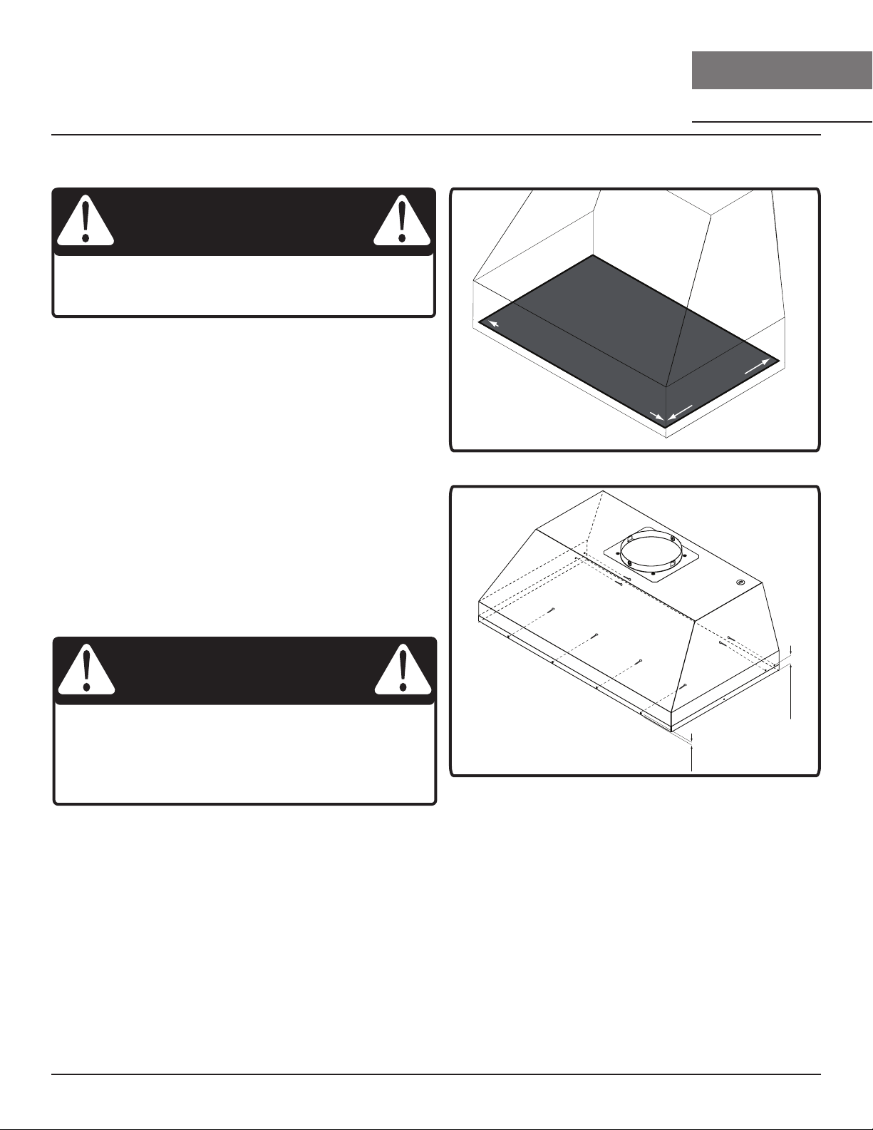
Safety Information
READ AND SAVE THESE INSTRUCTIONS
Your safety and the safety of others are very important.
We have provided many important safety messages in this
manual for your appliance. Always read and obey all safety
messages.
This is the Safety Alert Symbol. This symbol alerts you to
potential hazards that can cause severe bodily injury or death.
All safety messages will follow the Safety Alert Symbol and either
the words “DANGER” “WARNING” or “CAUTION”
DANGER
Danger means that failure to heed this safety statement may
result in severe injury or death.
WARNING
MONSOON II
INSERT
WARNING
WARNING - TO REDUCE THE RISK OF FIRE, ELECTRIC SHOCK,
OR INJURY TO PERSONS, OBSERVE THE FOLLOWING:
a) Use this unit only in the manner intended by the
manufacturer. If you have questions, contact the manufacturer.
b) Before servicing or cleaning unit, switch power o at service
panel and lock the service disconnecting means to prevent
power from being switched on accidentally. When the service
disconnecting means cannot be locked, securely fasten a
prominent warning device, such as a tag, to the service panel.
CAUTION
For General Ventilating Use Only. Do Not Use To Exhaust
Hazardous Or Explosive Materials And Vapors. Take care
when using cleaning agents or detergents. Suitable for use in
household cooking area.
Warning means that failure to heed this safety statement
may result in extensive product damage, serious personal
injury, or death.
CAUTION
Caution means that failure to heed this safety statement
may result in minor or moderate personal injury, property or
equipment damage.
General Safety
WARNING
To reduce the risk of fire or electric shock, do not use this fan
with any solid-state control device.
WARNING
WARNING - TO REDUCE THE RISK OF A RANGE TOP GREASE
FIRE:
a) Never leave surface units unattended at high settings.
Boilovers cause smoking and greasy spillovers that may ignite.
Heat oils slowly on low or medium settings.
b) Always turn insert ON when cooking at high heat or
when flambeing food. (i.e. Crepes Suzette, Cherries Jubilee,
Peppercorn Beef Flambe’).
c) Clean ventilating fans frequently. Grease should not be
allowed to accumulate on fan or filter.
d) Use proper pan size. Always use cookware appropriate for
the size of the surface element.
4
Monsoon II Use, Care, and Installation Guide
Page 4
ZEPHYRONLINE.COM
Safety Information
READ AND SAVE THESE INSTRUCTIONS
WARNING
WARNING - TO REDUCE THE RISK OF INJURY TO PERSONS
IN THE EVENT OF A RANGE TOP GREASE FIRE, OBSERVE THE
FOLLOWING:
a) SMOTHER FLAMES with a close-fitting lid, cookie sheet, or
metal tray, then turn o the burner. BE CAREFUL TO PREVENT
BURNS. If the flames do not go out immediately, EVACUATE AND
CALL THE FIRE DEPARTMENT.
b) NEVER PICK UP A FLAMING PAN – You may be burned.
c) DO NOT USE WATER, including wet dishcloths or towels – a
violent steam explosion will result.
d) Use an extinguisher ONLY if:
1) You know you have a Class ABC extinguisher, and you
already know how to operate it.
2) The fire is small and contained in the area where it
started.
3) The fire department is being called.
4) You can fight the fire with your back to an exit
Based on “Kitchen Firesafety Tips” published by NFPA.
WARNING
WARNING - TO REDUCE THE RISK OF FIRE, ELECTRIC SHOCK,
OR INJURY TO PERSONS, OBSERVE THE FOLLOWING:
a) Installation work and electrical wiring must be done by
qualified person(s) in accordance with all applicable codes and
standards, including fire-rated construction.
b) Sucient air is needed for proper combustion and
exhausting of gases through the flue (chimney) of fuel burning
equipment to prevent back drafting. Follow the heating
equipment manufacturer’s guideline and safety standards such
as those published by the National Fire Protection Association
(NFPA), and the American Society for Heating, Refrigeration
and Air Conditioning Engineers (ASHRAE), and the local code
authorities.
c) When cutting or drilling into wall or ceiling, do not damage
electrical wiring and other hidden utilities.
d) Ducted fans must always be vented to the outdoors.
e) If this unit is to be installed over a tub or shower, it must be
marked as appropriate for the application and be connected
to a GFCI (Ground Fault Circuit Interrupter) - protected branch
circuit.
WARNING
WARNING
TO REDUCE THE RISK OF FIRE, USE ONLY METAL DUCTWORK.
CAUTION
To reduce risk of fire and to properly exhaust air outside, do
not vent exhaust air into spaces within walls, ceilings, attics,
crawl spaces, or garages.
WARNING
Prop. 65 Warning for California Residents: This product may
contain chemicals known to the State of California to cause
cancer, birth defects, or other reproductive harm.
Monsoon II Use, Care, and Installation Guide
5
Page 5

PRO
Safety Information
MONSOON II
INSERT
READ AND SAVE THESE INSTRUCTIONS
Operation
► Always leave safety grilles and filters in place. Without these components, operating blowers could catch onto hair, fingers and
loose clothing.
► The manufacturer declines all responsibility in the event of failure to observe the instructions given here for installation,
maintenance and suitable use of the product. The manufacturer further declines all responsibility for injury due to negligence and
the warranty of the unit automatically expires due to improper maintenance.
NOTE: Please check www.zephyronline.com for revisions before doing any custom work.
Electrical Requirements
Important:
► Observe all governing codes and ordinances.
► It is the customer’s responsibility to be aware of these below:
► To contact a qualified electrical installer.
► To assure that the electrical installation is adequate and in conformance with National Electrical Code, ANSI/NFPA 70 latest
edition* or CSA standards C22.1-94, Canadian Electrical Code, Part 1 and C22.2 No.0-M91 - latest edition** and all local codes
and ordinances.
► If codes permit and a separate ground wire is used, it is recommended that a qualified electrician determine that the ground path
is adequate.
► Do not ground to a gas pipe.
► Check with a qualified electrician if you are not sure the insert is properly grounded.
► Do not have a fuse in the neutral or ground circuit.
► This appliance requires a 120V 60Hz electrical supply and connected to an individual properly grounded branch circuit protected
by a 15 or 20 ampere circuit breaker or time delay fuse. Wiring must be 2 wire with ground. Please also refer to Electrical Diagram
on product.
► A cable locking connector (not supplied) might also be required by local codes. Check with local requirements, purchase and
install appropriate connector if necessary.
* National Fire Protection Association Batterymarch Park, Quincy, Massachusetts 02269
** CSA International 8501 East Pleasant Valley Road, Cleveland, Ohio 44131-5575
Federal Communication Commission Interface Statement
► This equipment has been tested and found to comply with the limits for a Class B digital device, pursuant to Part 15 of the FCC
Rules. These limits are designed to provide reasonable protection against harmful interference in a residential installation.
► This equipment generates, uses and can radiate radio frequency energy and, if not installed and used in accordance with the
instructions, may cause harmful interference to radio communications. However, there is no guarantee that interference will not
occur in a particular installation. If this equipment does cause harmful interference to radio or television reception, which can be
determined by turning the equipment o and on, the user is encouraged to try to correct the interference by one of the following
measures:
► Reorient or relocate the receiving antenna.
► Increase the separation between the equipment and receiver.
► Connect the equipment into an outlet on a circuit dierent from that to which the receiver is connected.
► Consult the dealer or an experienced radio/TV technician for help.
6
Monsoon II Use, Care, and Installation Guide
Page 6
ZEPHYRONLINE.COM
#8 x 1/2” (12)
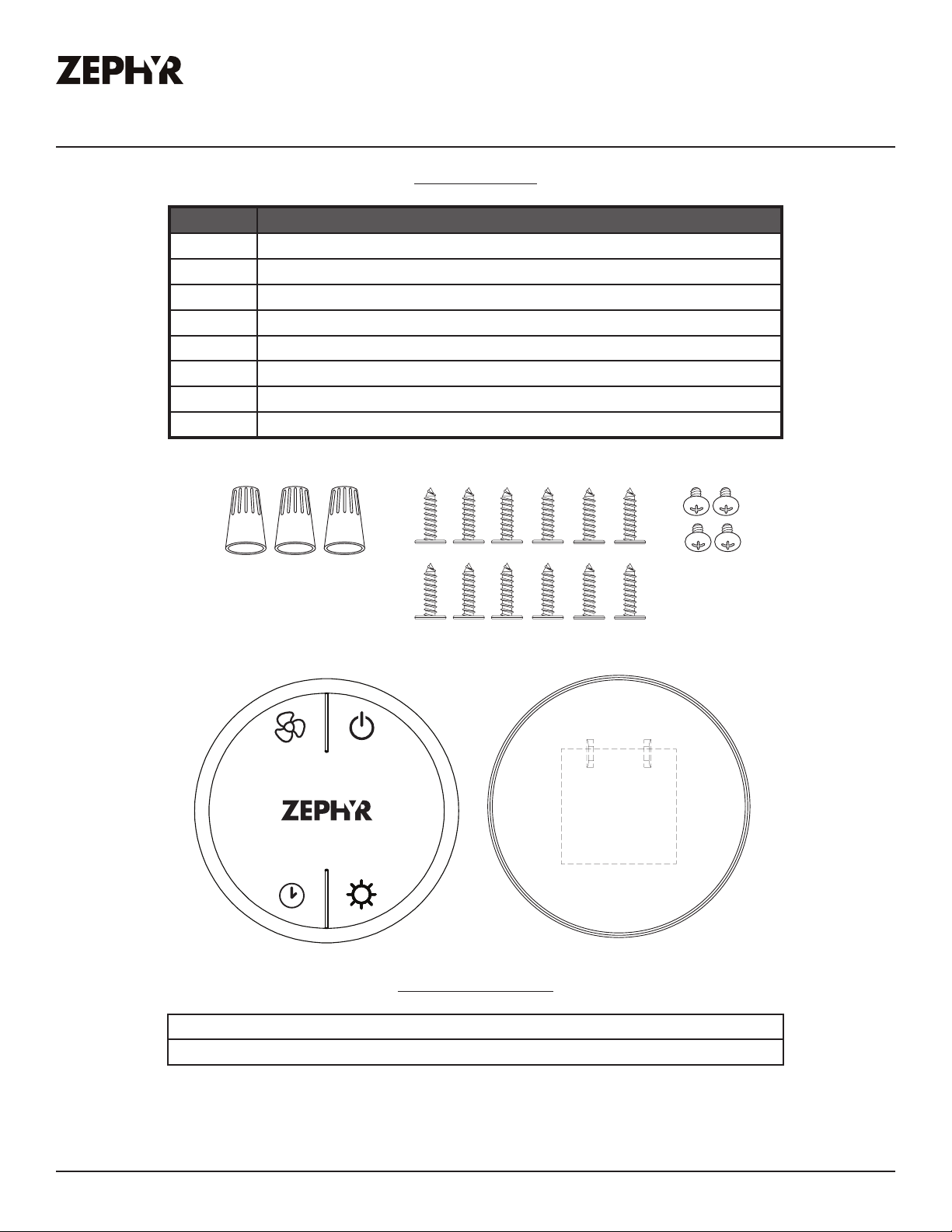
List of Materials
Parts Supplied
Quantity Part
1 Insert hood body
2 Pro bae filters (AK9334BS & AK9340BS)
3 Pro bae filters (AK9346BS & AK9352BS)
4 LumiLight LED, 6W (pre-installed)
1 Dual internal blower (pre-installed)
1 10” round duct collar
1 RF remote control (w/ battery & holder)
1 Hardware package
Wire Caps (3)
RF Remote Control (1) Remote Holder (1)
M4 x 6mm (4)
Parts Not Supplied
Ducting, conduit and all installation tools
Cable locking connector (if required by local codes)
Monsoon II Use, Care, and Installation Guide
7
Page 7
PRO
Installation Instructions
Ducting Calculation Sheet
Duct pieces
3- 1/ 4” x 10”
Rect.,
straight
6”, 7”, 8”, 10”
Round,
straight
3- 1/ 4” x 10”
Rect. 90
elbow
3- 1/ 4” x 10”
Rect. 45
elbow
3- 1/ 4” x 10”
Rect. 90
flat elbow
7” to 6” or
8” to 7” Round
tapered
reducer
6”, 7“, 8”
Round
in-line
damper
6”, 7”, 8”, 10”
Round,
0
90
elbow
6”, 7”, 8”, 10”
Round,
0
45
elbow
Equivalent number
length x used =
1 Ft. x ( ) =
1 Ft. x ( ) =
15 Ft. x ( ) =
0
9 Ft. x ( ) =
0
24 Ft. x ( ) =
0
25 Ft. x ( ) =
15
Ft. x ( ) =
15 Ft.
9 Ft. x ( ) =
Subtotal column 1 =
x ( ) =
To tal
Ft.
Ft.
Ft.
Ft.
Ft.
Ft.
Ft.
Ft.
Ft.
Ft.
Duct pieces
3- 1/ 4” x 10”
Rect. to
6” round
transition
3- 1/ 4” x 10”
Rect. to
6” round
transition
0
elbow
90
6” round to
3- 1/ 4” x 10”
rect.
transition
6” round to
3- 1/ 4” x 10”
rect.
transition
0
90
elbow
7” round to
3 1/ 4” x 10”
rect.
transition
7” round to
3- 1/ 4” x 10”
rect.
transition
0
90
elbow
3- 1/ 4” x 10”
Rect.
wall cap
with damper
6”, 7”, 8”, 10”
Round, wall
cap with
damper
6”, 7”, 8”, 10”
Round
roof cap
Equivalent number
length x used =
5 Ft. x ( ) =
20 Ft. x ( ) =
1 Ft. x ( ) =
16 Ft. x ( ) =
8 Ft. x ( ) =
23 Ft. x ( ) =
30 Ft. x ( ) =
30 Ft. x ( ) =
30 Ft. x ( ) =
MONSOON II
INSERT
To tal
Ft.
Ft.
Ft.
Ft.
Ft.
Ft.
Ft.
Ft.
Ft.
8
Maximum Duct Length: For satisfactory air movement,
the total duct length
should not exceed 150 equivalent feet.
Subtotal column 2 =
Subtotal column 1 =
Total ductwork =
Ft.
Ft.
Ft.
Monsoon II Use, Care, and Installation Guide
Page 8
Installation Instructions
ZEPHYRONLINE.COM
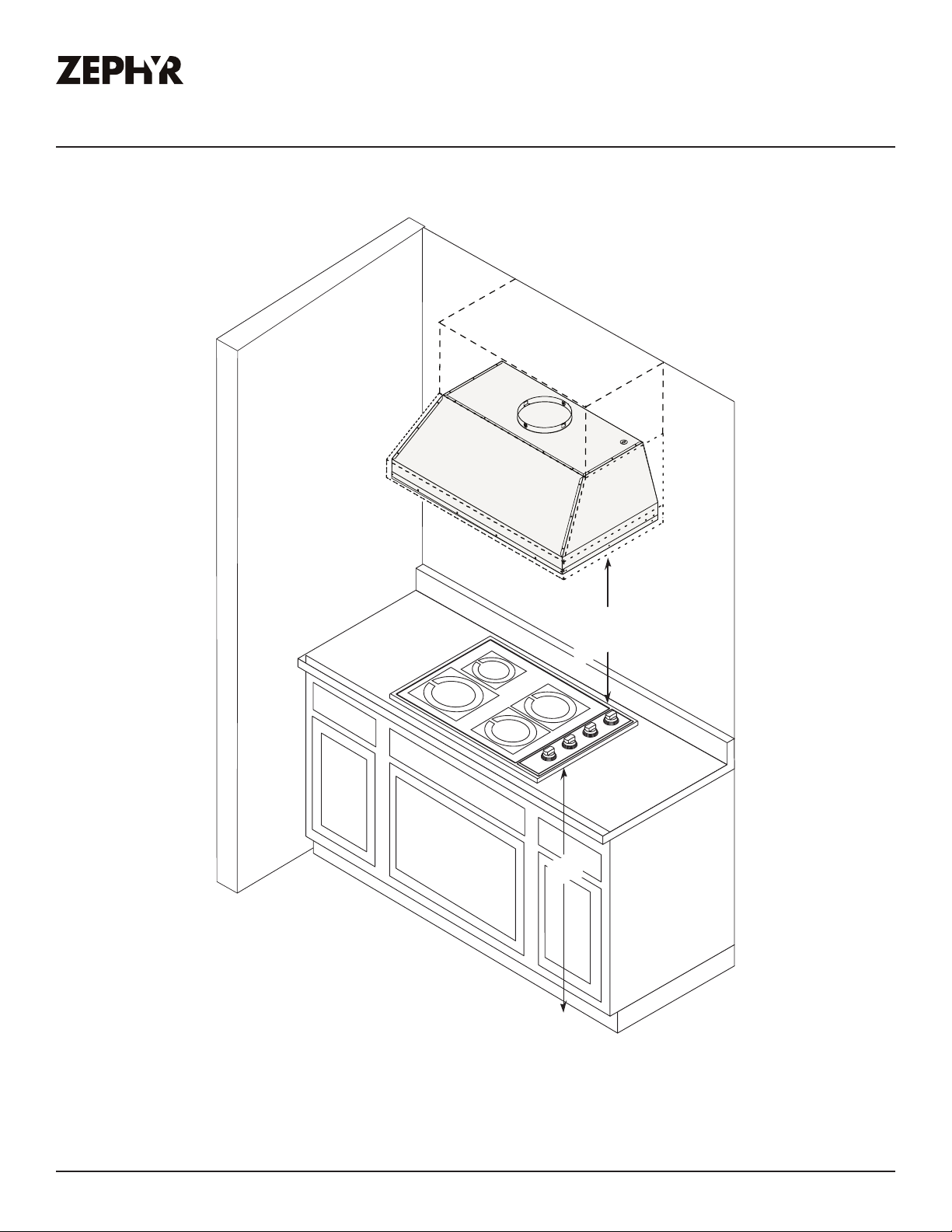
Mounting Height, Clearance, & Ducting
24” min.
36” max.
36”
Monsoon II Use, Care, and Installation Guide
9
Page 9

PRO
Installation Instructions
MONSOON II
INSERT
Mounting Height, Clearance, & Ducting
A minimum of 10” round duct must be used to maintain maximum air flow eciency.
Always use rigid type metal ducts only. Flexible ducts could restrict air flow by up to 50%.
Also use calculation (on page 11) to compute total available duct run when using elbows, transitions
and caps.
ALWAYS, when possible, reduce the number or transitions and turns. If long duct run is required,
increase duct size.
If turns or transitions are required; install as far away from hood duct output and as far apart,
between the two as possible.
Minimum mount height between range top to hood bottom should be no less than 24”.
Maximum mount height should be no higher than 36”.
It is important to install the hood at the proper mounting height. Hoods mounted too low could result
in heat damage and fire hazard; while hoods mounted too high will be hard to reach and will lose its
performance and eciency.
If available, also refer range manufacturer’s height clearance requirements and recommended hood
mounting height above range.
For shipment and installation damages:
► Please fully inspect unit for damage before installation.
► If the unit is damaged in shipment, return the unit to the store in which it was bought for repair or
replacement.
► If the unit is damaged by the customer, repair or replacement is the responsibility of the customer.
► If the unit is damaged by the installer (if other than the customer), repair of replacement must be
made by arrangement between customer and installer.
10
Monsoon II Use, Care, and Installation Guide
Page 10
Installation Instructions
Sot or crawl space
Roof Pitch w/
Flashing & Cap
side wall cap
w/ gravity
damper
side wall cap
w/ gravity damper
ZEPHYRONLINE.COM
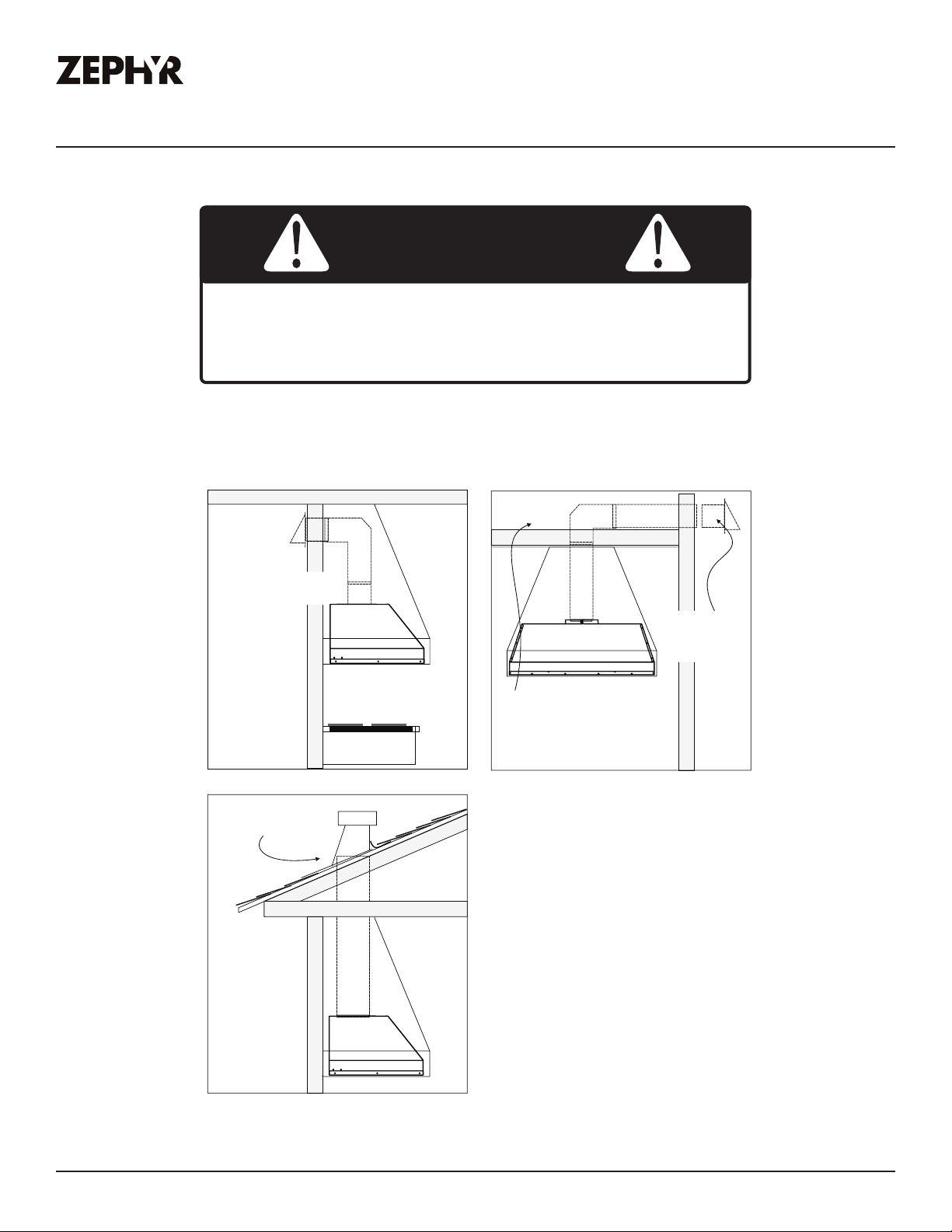
Ducting Options
WARNING
Fire Hazard: NEVER exhaust air or terminate ductwork into
spaces between walls, crawl spaces, ceilings, attics, or garages.
All exhaust must be ducted to the outside, unless using the
recirculating option.
► Use single wall rigid metal ductwork only.
► Fasten all connections with sheet metal screws and tape all joints w/ certified Silver Tape or Duct
Tape.
Monsoon II Use, Care, and Installation Guide
11
Page 11
PRO
Back View
Installation Instructions
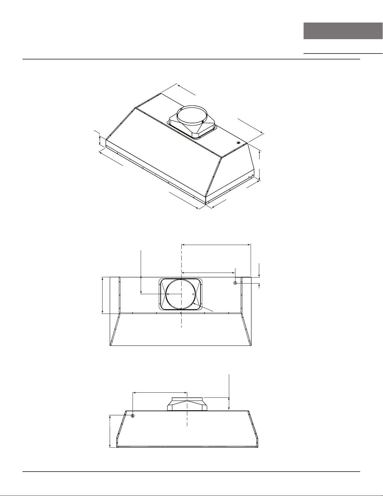
Hood Specications
3”
34-
46-
3/8”,
3/8
”, 52-
5-5/8”
40-
3/8
3/8
”,
”
3/4 View
28-
40-
3/8”
3/8
, 34-
”, 46-
(34”) 17-1/4”
(40”) 20-1/4”
(46”) 23-1/4”
(52”) 26-1/4”
(34”) 12”
(40”) 15”
(46”) 18”
(52”) 21”
1/8”
MONSOON II
INSERT
3/8
”,
12”
”
2
/
-1
2
2
2”
12”
elec.
k/o
Ø
1
0
”
C/L
Top View
(34”) 12”
(40”) 15”
(46”) 18”
(52”) 21”
elec.
k/o
10-3/8”
C/L
4-3/8”
12
Monsoon II Use, Care, and Installation Guide
Page 12
Installation Instructions
ZEPHYRONLINE.COM
Electrical Supply
WARNING
Electrical wiring must be done by qualified person(s) in
accordance with all applicable codes and standards. Turn o
electrical power at service entrance before wiring.
For personal safety, remove house fuse or open circuit breaker before beginning installation. Do not
use extension cord or adapter plug with this appliance.
Follow national electrical codes or prevailing local codes and ordinances.
This appliance requires a 120V 60Hz electrical supply, and connected to an individual, properly
grounded branch circuit, protected by a 15 or 20 ampere circuit breaker or time delay fuse. Wiring
must be 2 wire w/ ground. Please also refer to the Electrical Diagram labeled on product.
Cable Lock
A cable locking connector (not supplied) might be required by local codes. Check with local
requirements and codes, purchase and install appropriate connector if necessary. (FIG. A)
Cable Lock
FIG. A
Monsoon II Use, Care, and Installation Guide
13
Page 13
PRO
34-5/8” or 40-5/8” or 46-5/8” or 52-5/8”
22
-
3
/4
”
cut o
u
t
(AK9334)
(AK9340)
(AK9
3
52)
(AK9
3
4
6)
1/4”
1-1/8”
Installation Instructions
Preparation & Installation
CAUTION
At least two installers are required due to the
weight and size of the liner.
1. Remove all packing materials and protective
film prior to installation. Use caution during
installation to prevent scratches or damage to
the stainless steel.
2. Cut out an opening in the bottom of the
cabinet by following the dimensions in FIG. B.
3. Prepare liner for installation into cabinet by
following the steps on page 18.
MONSOON II
INSERT
FIG. B
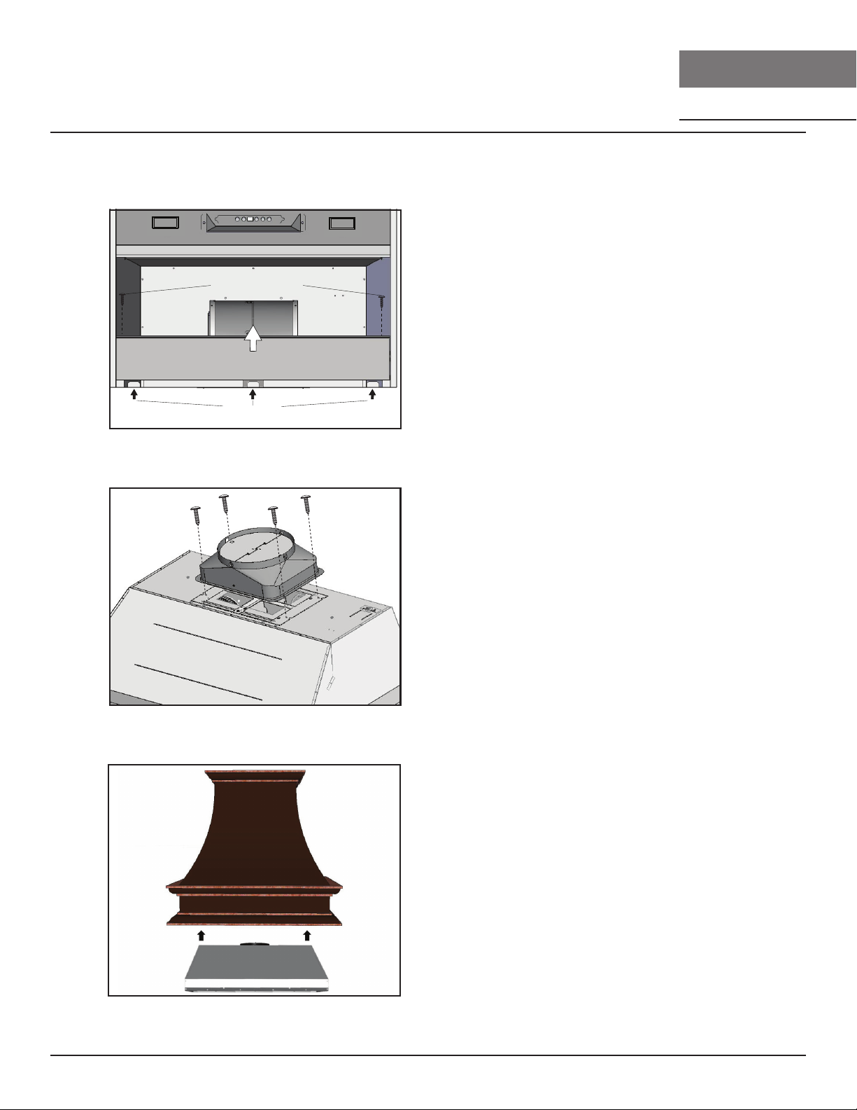
4. Lift liner into bottom opening of cabinet and
secure to interior of cabinet using (8) #8 x 1/2”
stainless steel screws; (4) screws in the front
and (4) screws in the sides. FIG. C.
WARNING
Make sure the surface you are securing the liner
to is capable of holding the weight of AK93.
Failure to do so may cause personal injury or
damage to cooking surface or counter.
5. Finalize installation of electrical and duct work. Seal duct work with certified aluminum duct tape.
Power on liner, check for leaks around duct tape and verify proper operation.
NOTE: If access to top of liner is not available after installation, electrical and duct work connection
may need to be made prior to installing the liner.
6. Re-install the previously removed bottom panel, side spacer panels (if applicable), grease tray,
and bae filters.
14
Monsoon II Use, Care, and Installation Guide
FIG. C
Page 14
ZEPHYRONLINE.COM
1
2
Preparation & Installation
Installation Instructions
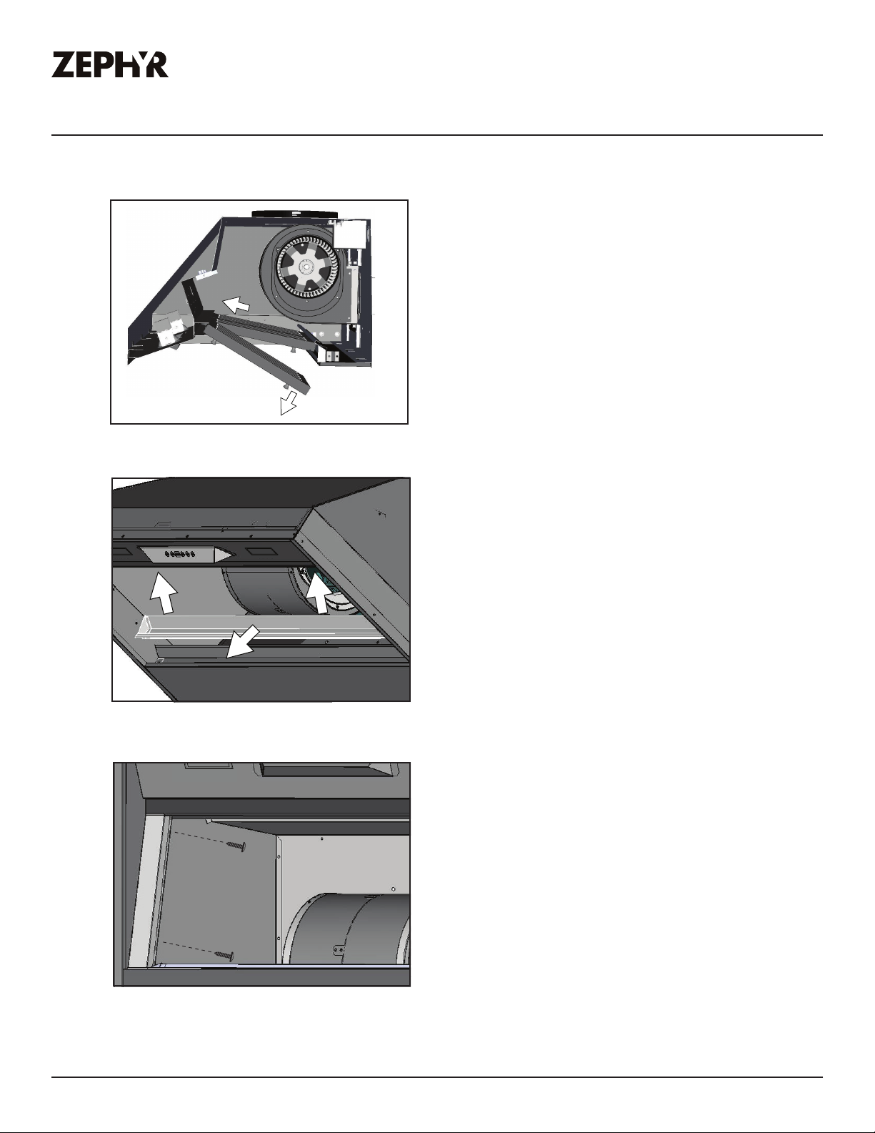
1. Remove bae filters by: 1) Pulling
filter toward front of liner. 2)
Pivoting rear of filter down.
2. Remove grease tray by: 1) Pulling
1
2
1
up on tray to release from bottom
panel. 2) Lifting tray out of liner
body.
3. Remove left and right side-spacer
panels by removing (2) screws
from behind each panel.
Monsoon II Use, Care, and Installation Guide
15
Page 15
PRO
Installation Instructions
Preparation & Installation
1
Bottom Panel Screws
2
Locking Tabs
MONSOON II
INSERT
4. Remove bottom panel by: 1)
Removing (2) screws from left and
right sides of bottom panel. 2)
Pulling bottom panel toward front
of liner to release from locking
tabs.
5. Secure 10” round ducting collar
to top of insert by (4) M4 x 6mm
screws.
6. Vertical ducting preparation is
complete. Refer to page 18, step
4 to complete installation.
16
Monsoon II Use, Care, and Installation Guide
Page 16
ZEPHYRONLINE.COM
1. Bl
By pr
- Airflo
codes and r
- T
- W
2. Speed Selection
- Pr
- If fan is on Speed 1 and is pr
- Pr
- If hood is o and is pr
A
- When A
- 5
- 390 CFM = Maximum 2 speeds
3
This featur
once
completely shut do
4
Switch ligh
5
The display windo
clean air indicator
Blower On/O
1
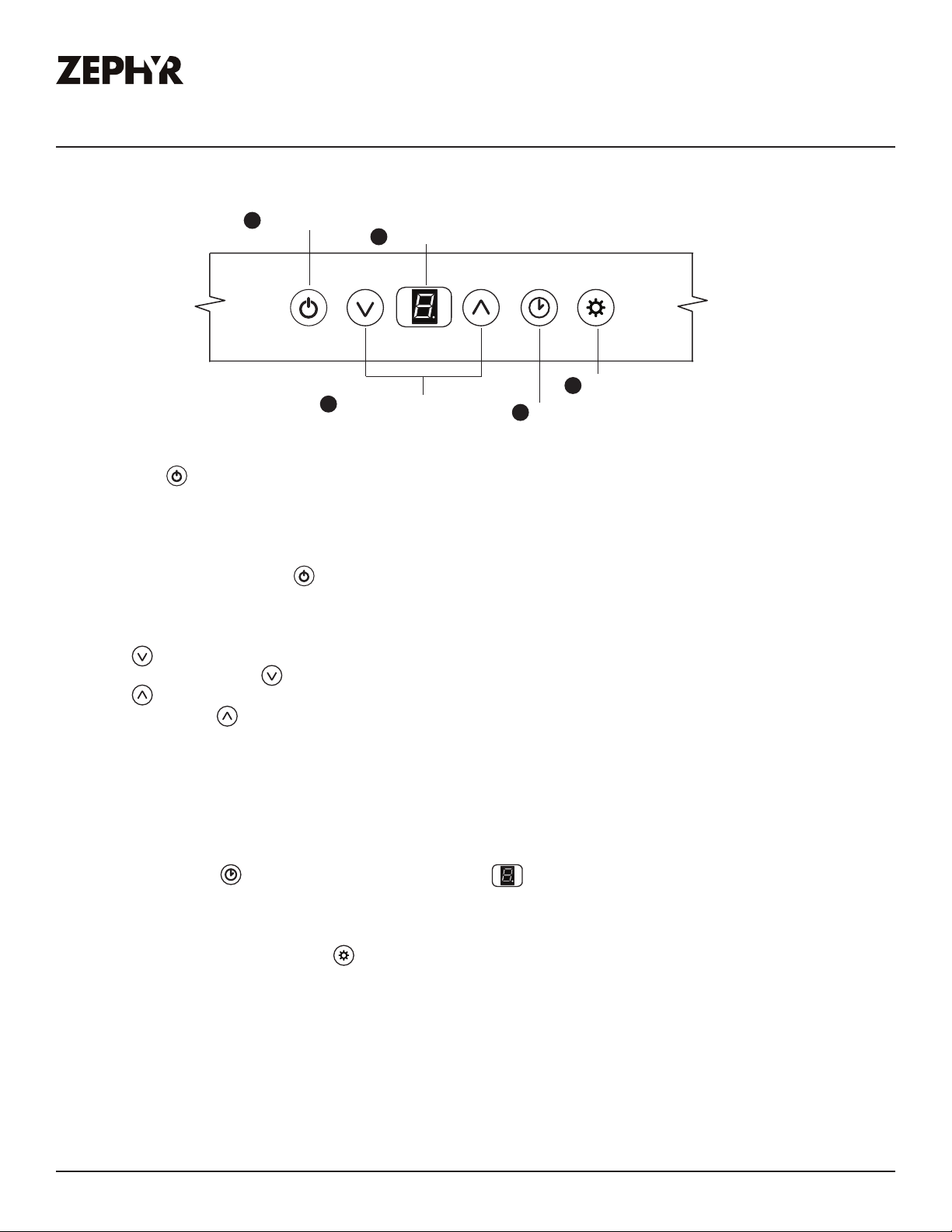
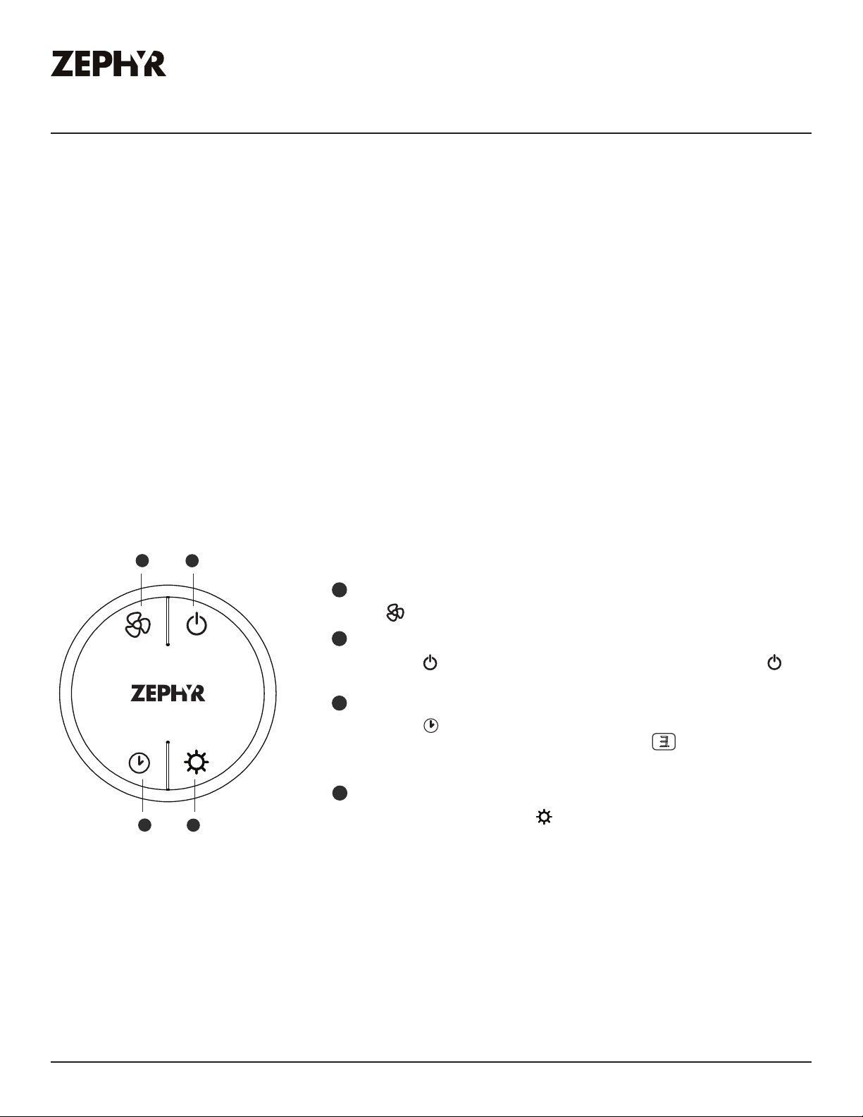
Touch Controls
ower On/O
essing the blower is switched on and o. When switched on, the blower starts up on speed level 1.
ACT Verification
w Control Technology (ACT) allows the installer to set the maximum blower CFM to align with local
o verify the maximum blower CFM:
number 3 displays = max. 590 CFM, and if number 2 displays = max. 390 CFM.
ess to decrease fan speed. 6, 5, 4, 3, 2, 1.
ess to increase fan speed. Fan On, 1, 2, 3, 4, 5, 6.
CT Enabled Speed Selections
90 CFM = Maximum 3 speeds
. Delay O
, a dot flashes in the lower right side of display indicating the function is on. The blower will
egulations.
ith hood o, hold the button for 3-4 seconds. If number 6 displays = default max. CFM, if
CT is enabled, the number of blower speeds will be reduced as follows:
e is used for programmed shut down of blower 5 minutes after the function is activated. Press
wn after 5 minutes.
Display (speed level, delay o, filter clean)
5
2
Adjust 6 Speed Levels
essed, the fan will power o.
essed, the fan will turn on speed 1.
Features & Controls
4
Lights Low/High/O
3
5 Min Delay O
. Lights Low/High/O
. Display Window
Monsoon II Use, Care, and Installation Guide
ts on to low by pressing once, press a second time for high and again to shut o lights.
w indicates speed levels and features such as bae filter clean reminder, delay o and
.
17
Page 17
PRO
Bae Filter Clean Reminder
om < A > to < >
Clean Air Indicator
While Clean Air is activ
alternate betw
Af
blo
will r
If the blo
Clean Air Function is in use
in
Clean Air Function
Clean Air is a featur
to r
mus
F
F
F
A
A
A
1
1
A
F
F
Features & Controls
Touch Controls
A set of bae filters are fitted by the factory, these bae filters are intended to filter
out residue from cooking. The filters need not be replaced on a regular basis but are
required to be kept clean. The BaeFilter Clean reminder function in the microprocessor will automatically indicate by a flashing when the bae filters need to be
cleaned after every 60 hours of use. Filters can be cleaned by hand with non-abrasive
soap or in a dishwasher. Heavily soiled filters should also be soaked in grease cutting
detergent prior to cleaning.
Bae Filter Clean Indicator
When flashes on the display, the bae
filters needo be cleaned. This will occur
after every 60 hours of use.
F
MONSOON II
INSERT
F
Clean Filters
display < F > flashes
F
Reset the filter clean reminder timer after
filters are cleaned and re-installed. With
hood o, press and hold for approximately 5 seconds until on display
disappears . The filter clean reminder
function is now reset and a new 60 hours
elapse cycle is initiated.
emove stagnant air in the kitchen. The Clean Air function is disabled by default and
t be enabled by the user.
ter 10 minutes of Clean Air operation, the
wer will power o and the 4 hour timer
eset.
terrupted and the timer will reset after.
F
e that turns on the blower on low speed every 4 hours for 10 minutes
e, the display will
1
A
een , , , .
wer speed is changed while the
A
1
, the cycle will be
To Reset
hold 5 sec. display from < F > to < >
F
To Enable
hold 3 sec.
and
To Disable
hold 3 sec. display fr
and
display < A > flashes
A
A
18
Monsoon II Use, Care, and Installation Guide
Page 18
Features & Controls
Blower On/
Speed Selection
5 Min Delay O
t corner of the hood display indicating the function
ZEPHYRONLINE.COM
RF Remote Control
FCC Caution
To assure continued compliance, any changes or modifications not expressly approved by the party
responsible for compliance could void the user’s authority to operate this equipment. (Example use only shielded interface cables when connecting to computer or peripheral device. This device
complies with Part 15 of the FCC Rules. Operation is subject to the following two conditions. (1)
This device may not cause harmful interference, and (2) This device must accept any interference
received, including interference that may cause undesired operation.
Synchronization
To create a unique link between your liner and remote control please follow these steps.
1. With liner o, press and hold the “lights” button on the liner until the letter “F” shows on the display
screen.
2. Press the “lights” button on the remote, the lights on the liner will turn on and synchronization is
complete.
RF Remote Control Functions
1
3
Blower On/
2
Power O
4
Lights Low/High/O
1
Blower On / Speed Selection
Press to power on blower and cycle through all six blower speeds.
2
Blower On / Power O
By pressing , the blowers will power on at the last speed setting. Press
again and the entire hood will power o, including lights.
Delay O
3
By pressing , the blower and lights will enter Delay O mode. A dot will
appear in the lower righ
is on. The blower will change to speed 1 and shut down after 5 minutes.
Lights Low/High/O
4
Switch lights to Low by pressing once, again to High and again to switch O.
Monsoon II Use, Care, and Installation Guide
19
Page 19
PRO
A
-
+
Features & Controls
MONSOON II
INSERT
RF Remote Control
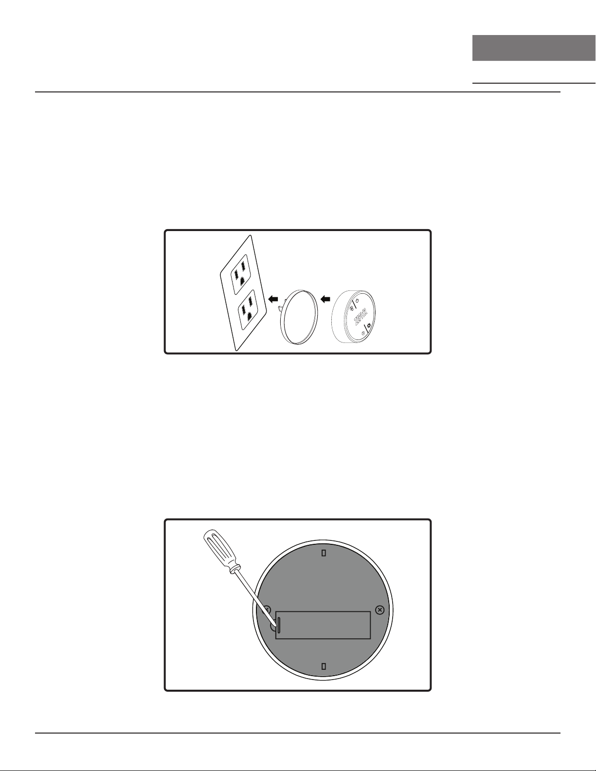
RF Remote Features
The RF remote control is equipped with a magnet on the back for easy storage. The remote may be
placed on any magnetic surface such as a refrigerator or the Zephyr remote holder, FIG. D. The
remote holder can be inserted into a standard electrical outlet for easy storage. Note: The remote
holder does not charge the RF remote.
Maximum remote control communication distance is 15 feet from the liner.
FIG. D
RF Remote Maintenance
Clean the remote control using non abrasive detergents.
Follow instructions below for replacing battery. Using a small flat head screwdriver, raise the cover of
the battery door (A) in order to access the battery compartment. FIG. E.
Remove the battery and replace with battery type A23 12V. Negative end of battery should face the
spring inside the remote.
Re-install battery door and recycle old battery.
20
FIG. E
Monsoon II Use, Care, and Installation Guide
Page 20

Maintenance
ZEPHYRONLINE.COM
Hood & Filter Cleaning
Surface Maintenance
► Do not use corrosive detergents, abrasive detergents or oven cleaners.
► Do not use any product containing chlorine bleach or any product containing chloride.
► Do not use steel wool or abrasive scrubbing pads which will scratch and damage surface.
Cleaning Stainless Steel
Clean periodically with warm soapy water and clean cotton cloth or micro fiber cloth. Always rub
in the direction of the stainless steel grain. To remove heavier grease build up use a liquid degreaser
detergent.
After cleaning use a non-abrasive stainless steel polish/cleaners, to polish and bu out the stainless
luster and grain. Always scrub lightly, with clean cotton cloth or micro fiber cloth and bu in the
direction of the stainless steel grain.
Cleaning the Bae Filters
The filters are intended to trap residue and grease from cooking. Although the filters should never
need replacing, they are required to be cleaned every 30 days or more often depending on cooking
habits.
Filters may be placed in dishwasher at low heat or soaked in hot soapy water Dry filters and re-install
before using hood.
Cleaning the Grease Tray
The grease tray is intended to catch residue and grease that may drip from the bae filters. The
grease tray should be cleaned when bae filters are cleaned. Clean the grease tray by soaking in
hot soapy water and gently scrubbing any residue o with a soft terry cloth. Dry grease tray and reinstall before using hood.
Monsoon II Use, Care, and Installation Guide
21
Page 21

PRO
1
2
1
1
2
Maintenance
MONSOON II
Installing the Bae Filters, FIG. F:
1. Place filter into top groove of the liner as shown and pull towards front of liner using handles.
2. Pivot back of filter upwards so it is angled in the liner.
3. Push filter into channel on back of liner to lock into place.
INSERT
FIG. F
Removing the Grease Tray
Grease tray has a hooked lip that attaches to bottom panel top edge.
Remove grease tray by:
1. Pull up on tray to release from bottom panel. FIG. G1
2. Pull tray out of liner body. FIG. G2
22
FIG. G
Monsoon II Use, Care, and Installation Guide
Page 22

Maintenance
ZEPHYRONLINE.COM
LumiLight LED
In the unlikely event that your LumiLight LED fails, please contact Zephyr to order replacement parts.
See the list of parts and accessories page for part numbers and contact information.
LED Removal (FIG. H):
1. Remove bae filters.
2. Remove light panel by five screws.
3. Disconnect LED light quick connector.
4. Push in the two side clips on the ends of the LED light.
5. Push LED light through the light panel opening.
FIG. H
Push the clip
Monsoon II Use, Care, and Installation Guide
23
Page 23

PRO
ACT™ Conversion
MONSOON II
INSERT
Airow Control Technology (ACT™)
Some local codes limit the maximum amount of CFM a range hood can move. ACT™ allows you
to control the maximum blower CFM of select Zephyr Ventilation range hoods without the need for
expensive make up air kits. ACT™ enables the installer to easily set the maximum blower speed to
one of two most commonly specified CFM levels, 590 or 390 CFM. The usage of ACT™ may not be
necessary for your installation. Please check your local codes for CFM restrictions.
By default, the maximum blower CFM is set to 1200.
CAUTION
Hood must be disconnected from the main power prior to
performing the conversion instructions listed below. Failure to do
so could result in personal injury or damage to the product.
CAUTION
After re-positioning the jumper and powering on the hood, the
CFM cannot be changed again.
24
Monsoon II Use, Care, and Installation Guide
Page 24

ACT™ Conversion
ZEPHYRONLINE.COM
Enabling ACT™
To enable ACT™:
1. Before hood installation, gain access to PC board by following the steps shown on FIG. I.
2. Change plastic jumper positioning as shown in FIG. J to set the desired maximum blower CFM.
3. Re-install PC board and continue with hood installation.
4. Remove the appropriate foil CFM sticker included with the hood literature and place inside the
hood body below the wiring diagram or in another clearly visible location.
To verify if your installer enabled ACT™:
1. With hood o, press and hold the power button for three seconds. If the number 6 displays =
defualt max. CFM, if the number 3 displays = max. 590 CFM, and if the number 2 displays = max.
390 CFM.
2. When ACT™ is enabled, the number of blower speeds will be reduced.
590 CFM = max. 3 speeds and 390 CFM = max. 2 speeds.
3. There should also be a foil label located inside the hood body near the wiring diagram that
indicates the blower CFM.
Monsoon II Use, Care, and Installation Guide
25
Page 25

PRO
PC Board
1
3
5
7
2
4
6
8
Jum p e r 5- 6 or 7-8
DEFAULT POSITION
Default Max. Blower CFM
Jum p e r 3- 4
Max. Blower CFM
Jum p e r 1- 2
Jumper Pins
Plastic
Jumper
1
3
5
7
2
4
6
8
1
3
5
7
2
4
6
8
1
3
5
7
2
4
6
8
Max. Blower CFM
590 390
ACT™ Conversion
Enabling ACT™
1. PC board located behind the light panel.
2. (If applicable) Remove both spacer panels by
2 screws for each spacer panel.
3. Remove 5 screws attaching light panel.
MONSOON II
INSERT
FIG. I
FIG. J
26
Monsoon II Use, Care, and Installation Guide
Page 26

ZEPHYRONLINE.COM
AK9334BS, AK9340BS, AK9346BS, AK9352BS CIRCUIT DIAGRAM
Wiring Diagram
BODY
OPTIONAL DUAL FAN
MOTOR
MOTOR
WHITE
GREEN
BODY
WHITE
GREEN
BODY
RED
YELLOW
GREY
BROWN
BLUE
BLUE
BROWN
GREY
RED
YELLOW
B/W
WHITE
BLUE
BROWN
RED
GREY
YELLOW
YELLOW
YELLOW
YELLOW
RED
YELLOW
YELLOW
YELLOW
YELLOW
GREEN
BLACK
WHITE
TRANSFORMER
ACT 590 CFM - Fan Max. 556W @ 4.6A
ACT 390 CFM - Fan Max. 381W @ 3.4A
Monsoon II Use, Care, and Installation Guide
27
Page 27

PRO
Troubleshooting
Possible Problem Possible Cause Solutions
After installation, the
unit doesn’t work.
Light works, but blower
is not turning.
The power source is not turned ON. Make sure the circuit breaker and the unit’s
power is ON.
The power line and the cable
locking connector is not connecting
properly.
The switch board or control board
wirings are disconnected.
The switch board or control board is
defective.
The wires on control board are loose. Make sure the wires on the control board
The blower wire is not connected. Make sure the blower wire is plugged into
The thermally protected system
detects if the blower is too hot to
operate and shuts the blower down.
Damaged capacitor. Change the capacitor.
Check the power connection with the unit is
connected properly.
Make sure the wirings at the switch board
and control board are connected properly.
Change the switch board or control board.
are connected properly.
the molex connector.
The blower will function properly after the
thermally protected system cool down.
MONSOON II
INSERT
Blower molex plug pin is not making
contact.
The blower is defective, possibly
seized.
The unit is vibrating. The blower is not secured in place. Tighten the blower in place.
Damaged blower wheel. Replace the blower.
The hood is not secured in place. Check the installation of the hood.
The unit is whistling. A filter is not in the correct position. Adjust the filters until the whistling stops.
The duct pipe connections are not
sealed or connected properly.
The blower is working,
but the lights are not.
The LED light connector is
disconnected.
Defective LED light. Change the LED light.
The switch board or control board is
defective.
Disconnect the blower molex plug, check
pins inside plug to see if pin is pushed inside
the plug too far. Reset pin if needed.
Change the blower.
Check the duct pipe connections to be sure
all connections are sealed properly.
Connect the LED light connector.
Change the switch board or control board.
28
Monsoon II Use, Care, and Installation Guide
Page 28

Troubleshooting
ZEPHYRONLINE.COM
Possible Problem Possible Cause Solutions
The hood is not venting
out properly.
The unit turns on by
itself.
Filter is vibrating Filter is loose. Adjust or change the filter.
RF Remote control does
not work.
Using the wrong size of ducting. Change the ducting to the correct size
The hood might be hanging to high
from the cook top.
The wind from the opened windows
or opened doors in the surrounding
area are aecting the ventilation of
the hood.
Blockage in the duct opening or
ductwork.
A spot light is shining directly onto
the switch controls.
Spring clip is broken on the filter. Change the spring clip.
Battery is dead. Replace battery with type A23 12v.
Poor communication with the liner. Remote control must be within 15 ft of liner.
Adjust the distance between the cook top
and the bottom of the hood within 24” and
36” range.
Close all the windows and doors to eliminate
the outside wind flow.
Remove all the blocking from the duct work
or duct opening.
The switch controls are light sensitive. A
direct light source onto the switch controls
may disrupt switch functions.
RF Remote lost communication with
the liner.
Reset liner and remote by switching power
o at the circuit breaker for 5 minutes.
Place remote on counter top near the liner
and switch the circuit breaker back on.
Monsoon II Use, Care, and Installation Guide
29
Page 29

PRO
List of Parts & Accessories
Description Part Number
Replacement Parts
LumiLight LED, 6W Z0B0047
Pro Bae Filter (each) 50210038
RF Remote Control 14000005
To order parts, visit us online at http://store.zephyronline.com.
MONSOON II
INSERT
30
Monsoon II Use, Care, and Installation Guide
Page 30

Limited Warranty
JAN21.0501
Limited Warranty
ZEPHYRONLINE.COM
TO OBTAIN SERVICE UNDER WARRANTY OR FOR ANY SERVICE RELATED QUESTIONS
United States Customers please call: 1-888-880-8368 or contact us at: zephyronline.com/contact
Canada Customers please call: 1-800-361-0799 or Email: service@distinctive-online.com
Zephyr Ventilation, LLC (referred to herein as “we” or “us”) warrants to the original consumer purchaser (referred to herein
as “you” or “your”) of Zephyr products (the “Products”) that such Products will be free from defects in materials or
workmanship as follows:
Three Year Limited Warranty for Parts: For three years from the date of your original purchase of the Products, we will
provide, free of charge, Products or parts (including LED light bulbs, if applicable) to replace those that failed due to
manufacturing defects subject to the exclusions and limitations below. We may choose, in our sole discretion, to repair or
replace parts before we elect to replace the Products.
One Year Limited Warranty for Labor: For one
provide, free of charge, the labor cost associated with repairing the Products or parts to replace those that failed due to
manufacturing defects subject to the exclusions and limitations below. After the first year from the date of your original
purchase, you are responsible for all labor costs associated with this warranty.
Warranty Exclusions: This warranty covers only repair or replacement, at our option, of defective Products or parts and
does not cover any other costs related to the Products including but not limited to: (a) normal maintenance and service
required for the Products and consumable parts such as fluorescent, incandescent or halogen light bulbs, mesh and charcoal filters and fuses; (b) any Products or
faulty installation or installation contrary to recommended installation instructions, improper maintenance or repair (other
than by us); (c) commercial or government use of the Products or use otherwise inconsistent with its intended purpose; (d)
natural wear of the finish of the Products or wear caused by improper maintenance, use of corrosive and abrasive cleaning
products, pads, and oven cleaner products; (e) chips, dents or cracks caused by abuse or misuse of the Products; (f) service
trips to your home to teach you how to use the Products; (g) damage to the Products caused by accident, fire, floods, acts
of God; or (h) Custom installations or alterations that impact serviceability of the Products. If you are outside our service
area, additional charges may apply for shipping costs for
travel cost to have a service technician come to your home to repair, remove or reinstall the Products. After the first year
from the date of your original purchase, you are also responsible for all labor costs associated with this warranty. All Products
must be installed by a qualified professional installer to be eligible for warranty repairs or service.
Limitations of Warranty. OUR OBLIGATION TO REPAIR OR REPLACE, AT OUR OPTION, SHALL BE YOUR SOLE
AND EXCLUSIVE REMEDY UNDER THIS WARRANTY. WE SHALL NOT BE LIABLE FOR INCIDENTAL,
CONSEQUENTIAL OR SPECIAL DAMAGES ARISING OUT OF OR IN CONNECTION WITH THE USE OR
PERFORMANCE OF THE PRODUCTS. THE EXPRESS WARRANTIES IN THE PRECEDING SECTION ARE
EXCLUSIVE AND IN LIEU OF ALL OTHER EXPRE
OTHER EXPRESS WARRANTIES FOR THE PRODUCTS, AND DISCLAIM AND EXCLUDE ALL WARRANTIES
IMPLIED BY LAW, INCLUDING THOSE OF MERCHANTABILITY AND FITNESS FOR A PARTICULAR PURPOSE.
Some states or provinces do not allow limitations on the duration of an implied warranty or the exclusion or limitation of
incidental or consequential damages, so the above limitations or exclusions may not apply to you. To the extent that
applicable law prohibits the exclusion of implied warranties, the duration of any applicable implied warranty is limited to the
same three-year and one-year periods described above if permitted by applicable law. Any oral or written description of the
Products is for the sole purpose of identifying the Products and shall not be construed as an express warr
using, implementing or permitting use of the Products, you shall determine the suitability of the Products for the intended
use, and you shall assume all risk and liability whatsoever in connection with such determination. We reserve the right to
use functionally equivalent refurbished or reconditioned parts or Products as warranty replacements or as part of warranty
service. This warranty is not transferable from the original purchaser and only applies to the consumer residence where the
Product was originally installed located in the United States and Canada. This warranty is not extended to resellers.
To Obtain Service Under Limited Warranty: To qualify for warranty service, you must: (a) notify us at the address or
telephone number stated below within 60 days of the discovery of the defect; (b) give the model number and serial
and (c) describe the nature of any defect in the Product or part. At the time of the request for warranty service, you must
present evidence of your proof of purchase and proof of the original purchase date. If we determine that the warranty
exclusions listed above apply or if you fail to provide the necessary documentation to obtain service, you will be responsible
for all shipping, travel, labor and other costs related to the services. This warranty is not extended or restarted upon warranty
repair or replacements.
Please check our website for any additional Product information, www.zephyronline.com
Zephyr, 2277 Harbor Bay Parkway, Alameda, CA 94502
y
ear from the date of your original purchase of the Products, we will
parts which have been subject to freight damage, misuse, negligence, accident,
warranty repair at our designated service locations and for the
WARRANTIES. WE HEREBY DISCLAIM AND EXCLUDE ALL
SS
nty. Prior to
a
number;
Monsoon II Use, Care, and Installation Guide
31
Page 31

PRO
Product Registration
Congratulations on the purchase of your
Zephyr product! Please take a moment to
register your new Zephyr product at
www.zephyronline.com/registration
IT’S IMPORTANT
Prompt registration helps in more ways
than one.
Ensures warranty coverage should you need
service.
Ownership verification for insurance purposes.
Notification of product changes or recalls.
MONSOON II
INSERT
Zephyr Ventilation | 2277 Harbor Bay Pkwy. | Alameda, CA 94502 | 1.888.880.8368
32
Monsoon II Use, Care, and Installation Guide
Page 32

WWW.ZEPHYRONLINE.COM
Ai
gy
TM
Monsoon II
AK9334BS, AK9340BS, AK9346BS, AK9352BS
EN Use, Care, and Installation Guide
FR Guide d’utilisation, d’entretien et d’installation
C
rflow Control Te chnolo
JUN22.0601
Page 33

ZEPHYRONLINE.COM
Consignes de sécurité ....................................................................... 4-6
Types d’avertissements de sécurité ..................................................... 4
Sécurité générale ................................................................................ 4
Opération ........................................................................................... 6
Exigences électriques ......................................................................... 6
Déclaration d’interface de la Federal Communication Commission ... 6
Liste de matériel .................................................................................. 7
Instructions d’installation ..................................................................8-16
Feuille de calcul pour le conduit d’aération ......................................... 8
Hauteur de montage, dégagement et gaine ..................................... 9-10
Options de conduits ...........................................................................11
Spécifications de la hotte ...................................................................12
Fourniture électrique ..........................................................................13
Raccord de câble ...............................................................................13
Préparation et installation ............................................................... 14-16
Fonctionnalités et commandes ......................................................... 17-20
Commandes tactiles .........................................................................17-18
Télécommande RF ...........................................................................19-20
Entretien ...........................................................................................21-23
Nettoyage de la hotte et du filtre ..................................................... 21-22
LumiLight LED ................................................................................... 23
Conversion ACT™ ............................................................................ 24-26
Technologie de contrôle du débit d’air (ACT™) ................................... 24
Activer ACT™ ...................................................................................25-26
Schéma de câblage ............................................................................ 27
Dépannage ..................................................................................... 28-29
Liste des pièces et accessoires ...........................................................30
Garantie limitée ................................................................................. 31
Enregistrement du produit .................................................................. 32
Table des matières
Page
Monsoon II Guide d’utilisation, d’entretien et d’installation
3
Page 34

PRO
Consignes de sécurité
LISEZ ET CONSERVEZ CES INSTRUCTIONS
Votre sécurité et celle des gens qui vous entourent sont très
importantes.
Ce manuel contient de nombreux messages de sécurité relatifs
à votre appareil. Lisez tous les messages et conformez-vous-y
en tout temps.
Voici le symbole d’alerte à la sécurité. Ce symbole vous informe
de possibles dangers qui pourraient entraîner de graves lésions
corporelles ou la mort. Tous les messages de sécurité suivent
le symbole d’alerte à la sécurité et comportent les mots «
DANGER », « AVERTISSEMENT » ou « ATTENTION ».
DANGER
Le mot « danger » signifie que le fait de ne pas tenir compte
de l’énoncé de sécurité peut entraîner une blessure grave ou
la mort.
AVERTISSEMENT
MONSOON II
INSÉRER
AVERTISSEMENT
AVERTISSEMENT - POUR RÉDUIRE LES RISQUES D’INCENDIE,
DE CHOC ÉLECTRIQUE OU DE BLESSURES AUX PERSONNES,
RESPECTEZ LES SUIVANTS:
a) N’utilisez cet appareil que de la manière prévue par le
fabricant. Si vous avez des questions, contactez le fabricant.
b) Avant l’entretien ou le nettoyage de l’unité, coupez
l’alimentation au panneau de service et verrouillez les moyens
de déconnexion de service pour éviter toute mise sous tension
accidentelle. Lorsque le moyen de déconnexion de service
ne peut pas être verrouillé, fixez solidement un dispositif
d’avertissement bien visible, tel qu’une étiquette, au panneau
de service.
ATTENTION
Pour Une Ventilation Générale Uniquement. Ne Pas Utiliser
Pour Évacuer Des Matières Et Des Vapeurs Dangereuses Ou
Explosives. Soyez prudent lorsque vous utilisez des produits
de nettoyage pour détergents. Convient pour une utilisation
dans la zone de cuisson domestique.
Le mot « avertissement » signifie que le fait de ne pas
tenir compte de l’énoncé de sécurité peut entraîner des
dommages importants au produit, une lésion corporelle
grave ou la mort.
ATTENTION
Le mot « attention » signifie que le fait de ne pas tenir
compte de l’énoncé de sécurité peut entraîner une lésion
corporelle mineure ou modérée, ou encore des dommages
au produit ou à la propriété.
Sécurité générale
ATTENTION
Pour réduire le risque d’incendie ou de choc électrique,
n’utilisez pas ce ventilateur avec un dispositif de commande
à semi-conducteurs.
AVERTISSEMENT
AVERTISSEMENT - POUR RÉDUIRE LE RISQUE D’INCENDIE DE
GRAISSE SUR LE HAUT DE CUISINIÈRE:
a) Ne laissez jamais les unités de surface sans surveillance
à des réglages élevés. Les débordements provoquent de la
fumée et des débordements graisseux qui peuvent s’enflammer.
Chauer les huiles lentement à des réglages faibles ou
moyens.
b) Allumez toujours la l’insert lorsque vous cuisinez à feu vif
ou lorsque vous flambez des aliments. (c’est-à-dire Crêpes
Suzette, Cerises Jubilee, Boeuf au Poivre Flambé »).
c) Nettoyez fréquemment les ventilateurs de ventilation. La
graisse ne doit pas s’accumuler sur le ventilateur ou le filtre.
d) Utilisez une taille de casserole appropriée. Utilisez toujours
des ustensiles de cuisine adaptés à la taille de l’élément de
surface.
4
Monsoon II Guide d’utilisation, d’entretien et d’installation
Page 35

ZEPHYRONLINE.COM
Consignes de sécurité
LISEZ ET CONSERVEZ CES INSTRUCTIONS
AVERTISSEMENT
AVERTISSEMENT - POUR RÉDUIRE LE RISQUE DE BLESSURE
DES PERSONNES EN CAS D’INCENDIE DE GRAISSE SUR LE
HAUT DE LA CUISINIÈRE, RESPECTEZ CE QUI SUIT:
a) DES FLAMMES PLUS INTELLIGENTES avec un couvercle bien
ajusté, une plaque à biscuits ou un plateau en métal, puis
éteignez le brûleur. FAITES ATTENTION À ÉVITER LES BRÛLURES.
Si les flammes ne s’éteignent pas immédiatement, ÉVACUER ET
APPELER LE DÉPARTEMENT DES INCENDIES.
b) NE JAMAIS RAMASSER UNE PLAQUE ENFLAMME - Vous
pourriez être brûlé.
c) N’UTILISEZ PAS D’EAU, ni de torchons ou de serviettes
humides - une violente explosion de vapeur en résultera.
d) Utilisez un extincteur UNIQUEMENT si:
1) Vous savez que vous possédez un extincteur de classe
ABC et vous savez déjà comment l’utiliser.
2) Le feu est petit et contenu dans la zone où il a
commencé.
3) Le service d’incendie est appelé.
4) Vous pouvez combattre le feu dos à une sortie
Basé sur “Kitchen Firesafety Tips” publié par la NFPA.
AVERTISSEMENT
AVERTISSEMENT
AVERTISSEMENT - POUR RÉDUIRE LES RISQUES D’INCENDIE,
DE DÉCHARGE ÉLECTRIQUE OU DE BLESSURES AUX
PERSONNES, RESPECTEZ CE QUI SUIT:
a) Les travaux d’installation et le câblage électrique doivent
être eectués par des personnes qualifiées conformément à
tous les codes et normes applicables, y compris la construction
résistant au feu.
b) Une quantité d’air susante est nécessaire pour une
combustion et une évacuation correctes des gaz par le conduit
de fumée (cheminée) de l’équipement à combustible pour
empêcher le refoulement. Suivez les directives et les normes
de sécurité du fabricant de l’équipement de chauage, telles
que celles publiées par la National Fire Protection Association
(NFPA), l’American Society for Heating, Refrigeration and Air
Conditioning Engineers (ASHRAE) et les autorités locales du
code.
c) Lorsque vous coupez ou percez dans un mur ou un plafond,
n’endommagez pas le câblage électrique et les autres services
publics cachés.
d) Les ventilateurs à conduit doivent toujours être ventilés vers
l’extérieur.
e) Si cet appareil doit être installé au-dessus d’une baignoire
ou d’une douche, il doit être marqué comme approprié pour
l’application et être connecté à un circuit de dérivation protégé
par un disjoncteur de fuite à la terre (GFCI).
AVERTISSEMENT
POUR RÉDUIRE LES RISQUES D’INCENDIE, UTILISEZ
UNIQUEMENT DES CONDUITS MÉTALLIQUES.
ATTENTION
Pour réduire les risques d’incendie et pour évacuer
correctement l’air extérieur, ne pas évacuer l’air évacué dans
les espaces à l’intérieur des murs, plafonds, greniers, vides
sanitaires ou garages.
Prop. 65 Avertissement pour les résidents de Californie: Ce
produit peut contenir des produits chimiques reconnus par
l’État de Californie comme pouvant provoquer le cancer,
des malformations congénitales ou d’autres troubles de la
AVERTISSEMENT
Monsoon II Guide d’utilisation, d’entretien et d’installation
reproduction.
5
Page 36

PRO
Consignes de sécurité
MONSOON II
INSÉRER
LISEZ ET CONSERVEZ CES INSTRUCTIONS
Opération
► Laissez toujours les grilles de sécurité et les filtres en place. Sans ces composants, les souantes en fonctionnement pourraient
s’accrocher aux cheveux, aux doigts et aux vêtements amples.
► Le fabricant décline toute responsabilité en cas de non-respect des instructions données ici pour l’installation, la maintenance et
l’utilisation appropriée du produit. Le fabricant décline en outre toute responsabilité en cas de blessure due à une négligence et la
garantie de l’unité expire automatiquement en raison d’un mauvais entretien.
REMARQUE: veuillez consulter www.zephyronline.com pour les révisions avant d’eectuer tout travail personnalisé.
Exigences électriques
Important:
► Respectez tous les codes et ordonnances en vigueur.
► Il est de la responsabilité du client d’en prendre connaissance ci-dessous:
► Pour contacter un installateur électrique qualifié.
► Pour garantir que l’installation électrique est adéquate et conforme au National Electrical Code, ANSI / NFPA 70 dernière édition *
ou aux normes CSA C22.1-94, Code canadien de l’électricité, partie 1 et C22.2 No.0-M91 - dernière édition ** et tous les codes et
ordonnances locaux.
► Si les codes le permettent et qu’un fil de terre séparé est utilisé, il est recommandé qu’un électricien qualifié détermine que le
chemin de terre est adéquat.
► Ne pas mettre à la terre un tuyau de gaz.
► Vérifiez auprès d’un électricien qualifié si vous n’êtes pas sûr que la l’insert est correctement mise à la terre.
► Ne pas avoir de fusible dans le circuit neutre ou de terre.
► Cet appareil nécessite une alimentation électrique de 120 V à 60 Hz et est connecté à un circuit de dérivation individuel
correctement mis à la terre protégé par un disjoncteur de 15 ou 20 ampères ou un fusible temporisé. Le câblage doit être à 2 fils
avec mise à la terre. Veuillez également vous référer au schéma électrique du produit.
► Un connecteur de verrouillage de câble (non fourni) peut également être requis par les codes locaux. Vérifiez les exigences locales,
achetez et installez le connecteur approprié si nécessaire.
* National Fire Protection Association Batterymarch Park, Quincy, Massachusetts 02269
** CSA International 8501 East Pleasant Valley Road, Cleveland, Ohio 44131-5575
Déclaration d’interface de la Federal Communication Commission
► Cet équipement a été testé et déclaré conforme aux limites d’un appareil numérique de classe B, conformément à la partie 15 des
règles FCC. Ces limites sont conçues pour fournir une protection raisonnable contre les interférences nuisibles dans une installation
résidentielle.
► Cet équipement génère, utilise et peut émettre de l’énergie radiofréquence et, s’il n’est pas installé et utilisé conformément aux
instructions, peut provoquer des interférences nuisibles aux communications radio. Cependant, il n’y a aucune garantie que
des interférences ne se produiront pas dans une installation particulière. Si cet équipement cause des interférences nuisibles à
la réception de la radio ou de la télévision, ce qui peut être déterminé en éteignant et en rallumant l’équipement, l’utilisateur est
encouragé à essayer de corriger les interférences par l’une des mesures suivantes:
► Réorientez ou déplacez l’antenne de réception.
► Augmentez la séparation entre l’équipement et le récepteur.
► Connectez l’équipement à une prise sur un circuit diérent de celui sur lequel le récepteur est connecté.
► Consultez le revendeur ou un technicien radio / TV expérimenté pour obtenir de l’aide.
6
Monsoon II Guide d’utilisation, d’entretien et d’installation
Page 37

ZEPHYRONLINE.COM
(4) M4 x 6mm
(3) capuchons de connexion
(12) #8 x 1/2 po
(1) commande à distance RF (1) support à commande
Liste de matériel
Pièces fournies
Quantité Partie
1 Insérer le corps de la hotte
2 Filtres à chicane pro (AK9334BS et AK9340BS)
3 Filtres à chicane pro (AK9346BS et AK9352BS)
4 LumiLight LED, 6 W (préinstallé)
1 Double ventilateur interne (pré-installé)
1 Collier de conduit rond de 10 po
1 Télécommande RF (avec batterie et support)
1 Pack matériel
Conduits, conduits et tous les outils d’installation
Raccord de câble (si requis par les codes locaux)
Pièces non fournies
Monsoon II Guide d’utilisation, d’entretien et d’installation
7
Page 38

PRO
Instructions d’installation
Feuille de calcul pour le conduit d’aération
Pièces de conduit
3- 1/ 4” x 10”
rect., droit
6”, 7”, 8”, 10”
circ., droit
3- 1/ 4” x 10”
rect.,
coude à 90º
3- 1/ 4” x 10”
rect.,
coude à 45º
3- 1/ 4” x 10”
rect.,
coude plat
à 90º
7” to 6” or
8” to 7” circ.
reducteur
conique
6”, 7“, 8”
circ.
bouchone de
l’air
6”, 7”, 8”, 10”
circ.,
coude à 90º
6”, 7”, 8”, 10”
coude à 45º
Longueur x
Nombre utilisé
1 pi x ( ) =
1 pi x ( ) =
15 pi x ( ) =
9 pi x ( ) =
24 pi x ( ) =
25 pi x ( ) =
15
pi x ( ) =
15 pi
9 pi x ( ) =
=
x ( ) =
Sous-total - colonne 1=
To tal
pi
pi
pi
pi
pi
pi
pi
pi
pi
pi
Pièces de conduit
6” circ. à
rect. de
3-1/4" x 10"
6” circ. à
rect. de
3-1/4" x 10",
coude à 90º
6” circ. à
rect. de
3-1/4" x 10"
6” circ. à
rect. de
3-1/4" x 10",
coude à 90º
7” circ. à
rect. de
3-1/4" x 10"
7” circ. à
rect. de
3-1/4" x 10",
coude à 90º
3-1/ 4” x 10”
embout mural
rect./registre
6”, 7”, 8”, 10”
embout
mural
circ./registre
6”, 7”, 8”, 10”
chapeau de
toiture circ.
Longueur x
Nombre utilisé
5 pi x ( ) =
20 pi x ( ) =
1 pi x ( ) =
16 pi x ( ) =
8 pi x ( ) =
23 pi x ( ) =
30 pi x ( ) =
30 pi x ( ) =
30 pi x ( ) =
=
MONSOON II
INSÉRER
To tal
pi
pi
pi
pi
pi
pi
pi
pi
pi
Longueur maximale du conduit d’aération :
Pour un mouvement d’air convenable, la longueur totale d’un conduit
d’aération ne devrait pas compter plus que l’équivalent de 150 pieds.
8
Monsoon II Guide d’utilisation, d’entretien et d’installation
Sous-total - colonne 2 =
Sous-total - colonne 1 =
Total du conduit =
pi
pi
pi
Page 39

Instructions d’installation
ZEPHYRONLINE.COM
Hauteur de montage, dégagement et gaine
24 po min.
36 po max.
36 po
Monsoon II Guide d’utilisation, d’entretien et d’installation
9
Page 40

PRO
Instructions d’installation
MONSOON II
INSÉRER
Hauteur de montage, dégagement et gaine
Un conduit rond d’au moins 10 po doit être utilisé pour maintenir une ecacité maximale du débit
d’air.
Utilisez toujours des conduits métalliques de type rigide uniquement. Les conduits flexibles peuvent
restreindre le débit d’air jusqu’à 50%.
Utilisez également le calcul (à la page 11) pour calculer la longueur totale de conduit disponible
lorsque vous utilisez des coudes, des transitions et des capuchons.
TOUJOURS, lorsque cela est possible, réduire le nombre de transitions et de virages. Si un long trajet
de conduit est nécessaire, augmentez la taille du conduit.
Si des virages ou des transitions sont nécessaires; installer le plus loin possible de la sortie du conduit
de la hotte et aussi loin que possible entre les deux.
La hauteur de montage minimale entre le haut de la cuisinière et le bas de la hotte ne doit pas être
inférieure à 24 po.
La hauteur de montage maximale ne doit pas dépasser 36 po.
Il est important d’installer la hotte à la bonne hauteur de montage. Les hottes montées trop bas
peuvent entraîner des dommages causés par la chaleur et un risque d’incendie; tandis que les hottes
montées trop haut seront diciles à atteindre et perdront leurs performances et leur ecacité.
Si disponible, reportez-vous également aux exigences de dégagement en hauteur du fabricant de la
cuisinière et à la hauteur de montage recommandée de la hotte au-dessus de la cuisinière.
Pour les dommages liés à l’expédition et à l’installation:
► Veuillez inspecter complètement l’unité pour déceler tout dommage avant l’installation. Si
l’appareil est endommagé lors de l’expédition, renvoyez-le au magasin où il a été acheté pour
réparation ou remplacement.
► Si l’appareil est endommagé par le client, la réparation ou le remplacement est à la charge du
client.
► Si l’unité est endommagée par l’installateur (si autre que le client), la réparation du remplacement
doit être eectuée par arrangement entre le client et l’installateur.
10
Monsoon II Guide d’utilisation, d’entretien et d’installation
Page 41

Instructions d’installation
Sote ou vide sanitaire
Pente de toit avec
solin et capuchon
capuchon de
paroi latérale
avec
amortisseur
de gravité
capuchon de paroi
latérale avec
amortisseur
de gravité
ZEPHYRONLINE.COM
Options de conduits
ATTENTION
Risque d’incendie: NE JAMAIS évacuer l’air ni terminer de
conduits dans des espaces entre les murs, les vides sanitaires,
les plafonds, les greniers ou les garages. Tout l’échappement
doit être canalisé vers l’extérieur, à moins d’utiliser l’option de
recirculation.
► Utilisez uniquement des conduits métalliques rigides à paroi simple.
► Fixez toutes les connexions avec des vis à tôle et collez tous les joints avec du ruban argenté ou du
ruban adhésif.
Monsoon II Guide d’utilisation, d’entretien et d’installation
11
Page 42

PRO
Vue de dessus
Vue 3/4
Vue arrière
3 po
12 po
2
2
-1
/
2
po
5-5/8 po
(34 po) 17-1/4 po
(40 po) 20-
1/4
po
(46 po) 23-
1/4 po
(52 po) 26-
1/4 po
C/L
Ø
1
0
po
(34 po) 12 po
(40 po) 15 po
(46 po) 18 po
(52 po) 21 po
2 po
elec.
k/o
10-
3/8
po
(34 po) 12 po
(40 po) 15 po
(46 po) 18 po
(52 po) 21 po
4-3/8 po
elec.
k/o
28-
3/8 po
, 34-
3/8
po,
34-
3/8 po,
40-
3/8
po,
40-
3/8
po, 46-
1/8 po
46-
3/8
po, 52-
3/8
po
C/L
12”
Instructions d’installation
Spécications de la hotte
MONSOON II
INSÉRER
12
Monsoon II Guide d’utilisation, d’entretien et d’installation
Page 43

Instructions d’installation
Raccord de câble
ZEPHYRONLINE.COM
Fourniture électrique
ATTENTION
Le câblage électrique doit être eectué par des personnes
qualifiées conformément à tous les codes et normes applicables.
Cette hotte doit être correctement mise à la terre. Coupez
l’alimentation électrique à l’entrée de service avant le câblage.
Pour votre sécurité personnelle, retirez le fusible de la maison ou ouvrez le disjoncteur avant de
commencer l’installation. N’utilisez pas de rallonge ni de fiche d’adaptateur avec cet appareil.
Suivez les codes électriques nationaux ou les codes et règlements locaux en vigueur.
Cet appareil nécessite une alimentation électrique de 120 V 60 Hz et est connecté à un circuit de
dérivation individuel correctement mis à la terre, protégé par un disjoncteur de 15 ou 20 ampères
ou un fusible temporisé. Le câblage doit être à 2 fils avec terre. Veuillez également vous référer au
schéma électrique étiqueté sur le produit.
Raccord de câble
Un connecteur de verrouillage de câble (non fourni) peut être requis par les codes locaux. Vérifiez les
exigences et les codes locaux, achetez et installez le connecteur approprié si nécessaire. (FIG. A)
FIG. A
Monsoon II Guide d’utilisation, d’entretien et d’installation
13
Page 44

PRO
34-5/8 po or 40-5/8 po or 46-5/8 po ou 52-5/8 po
22-3/4 po
c
o
u
pé
(AK9334)
(AK9340)
(AK9
3
52)
(AK9
3
46)
1/4 po
1-1/8 po
Instructions d’installation
Préparation et installation
AVERTISSEMENT
Au moins deux installateurs sont nécessaires en
raison du poids et de la taille de la doublure.
1. Retirez tous les matériaux d’emballage et le film
protecteur avant l’installation. Soyez prudent
lors de l’installation pour éviter les rayures ou
les dommages à l’acier inoxydable.
2. Découpez une ouverture dans le bas de
l’armoire en suivant les dimensions de la FIG. B.
3. Préparez la doublure pour l’installation dans
l’armoire en suivant les étapes de la page 18.
MONSOON II
INSÉRER
FIG. B
4. Soulevez la doublure dans l’ouverture inférieure
de l’armoire et fixez-la à l’intérieur de l’armoire
à l’aide de (8) vis en acier inoxydable n°8 x 1/2
po; (4) vis à l’avant et (4) vis sur les côtés. FIG.
C.
ATTENTION
Assurez-vous que la surface sur laquelle vous
fixez la doublure est capable de supporter
le poids de l’AK93. Le non-respect de cette
consigne peut entraîner des blessures corporelles
ou endommager la surface de cuisson ou le
comptoir.
5. Finaliser l’installation des travaux d’électricité et de conduits. Sceller les conduits avec du ruban
adhésif en aluminium certifié. Mettez la doublure sous tension, vérifiez s’il y a des fuites autour du
ruban adhésif et vérifiez son bon fonctionnement.
REMARQUE: Si l’accès au dessus de la gaine n’est pas disponible après l’installation, il se peut que le
raccordement électrique et des conduits doive être eectué avant d’installer la gaine.
Monsoon II Guide d’utilisation, d’entretien et d’installation
6. Réinstallez le panneau inférieur, les panneaux d’entretoise latéraux (le cas échéant), le bac à
graisse et les filtres déflecteurs précédemment retirés.
14
FIG. C
Page 45

ZEPHYRONLINE.COM
1
2
Préparation et installation
Instructions d’installation
1. Retirez les filtres déflecteurs en:
1) Tirant le filtre vers l’avant de
la doublure. 2) Pivotement de
l’arrière du filtre vers le bas.
2. Retirez le plateau à graisse en:
1) Tirant sur le plateau pour le
1
2
1
dégager du panneau inférieur. 2)
Soulever le plateau hors du corps
de la doublure.
3. Retirez les panneaux d’entretoise
latéraux gauche et droit en
retirant les (2) vis derrière chaque
panneau.
Monsoon II Guide d’utilisation, d’entretien et d’installation
15
Page 46

PRO
Instructions d’installation
Préparation et installation
4. Retirez le panneau inférieur en:
1
Vis du panneau inférieur
2
Verrouillage des onglets
MONSOON II
INSÉRER
1) Retirez les (2) vis des côtés
gauche et droit du panneau
inférieur. 2) Tirer le panneau
inférieur vers l’avant de la
doublure pour le dégager des
languettes de verrouillage.
5. Fixez le collier de conduit rond
de 10 po au sommet de l’insert à
l’aide de (4) vis M4 x 6 mm.
6. La préparation des conduits
verticaux est terminée. Reportezvous à la page 18, étape 4 pour
terminer l’installation.
16
Monsoon II Guide d’utilisation, d’entretien et d’installation
Page 47

ZEPHYRONLINE.COM
Ventilateur Marche/Arrêt
1
Commandes tactiles
1. Ventilateur : Marche/Arrêt
Appuyez sur pour allumer ou éteindre le ventilateur. Lorsque vous l’allumez, le ventilateur se met en
marche à la vitesse 1.
Vérification de la ACT:
- La technologie de contrôle du débit d’air permet à l’installeur d’ajuster la quantité maximale d’évacuation
- Pour vérifier le CFM maximum du ventilateur:
- Le capot étant éteint, maintenez le bouton enfoncé pendant 3 à 4 secondes. Si le numéro 6
3
de pi /min du ventilateur afin de respecter les codes et règlements en vigueur.
s'ache = max. CFM, si le numéro 3 s'ache = max. 590 CFM, et si le numéro 2 s'ache = max. 390
3
pi /min.
Fonctionnalités et commandes
Acheur (Vitesse, arrêt à retardement, nettoyage des filtres)
5
4
Lumière: faible, élevée, désactivée
2
Choix de 6 vitesses
3
Arrêt à retardement (5 min.)
2. Choix de vitesse
- Appuyez sur pour diminuer la vitesse du ventilateur. 6, 5, 4, 3, 2, 1.
- Si le ventilateur est à la vitesse 1 et que est enfoncé, le ventilateur s'éteint.
- Appuyez sur pour augmenter la vitesse du ventilateur. Ventilateur activé, 1, 2, 3, 4, 5, 6.
- Si le capot est éteint et que est enfoncé, le ventilateur se met en marche à la vitesse 1.
Choix de vitesse avec ACT activée
- Lorsque la ACT est activée, le nombre de vitesses du ventilateur est réduit comme suit:
- 590 pi /min = 3 vitesses maximum
- 390 pi /min = 2 vitesses maximum
3. Arrêt à retardement
Cette fonction est utilisée pour programmer l’arrêt automatique du ventilateur et des lumières 5 minutes
après son activation. Lorsque vous appuyez une fois sur , un point clignote dans la partie inférieure
droite de l’acheur pour vous confirmer que la fonction a été activée. La hotte s’éteint complètement après 5 minutes.
4. Lumière: faible, élevée, désactivée
Allumez les lumières à faible en appuyant une fois sur , appuyez une deuxième fois pour haut et à
nouveau pour éteindre les lumières.
5. Acheur
L’écran de l’acheur indique la vitesse de ventilateur choisie ainsi que certaines fonctions, comme le
rappel de nettoyage des filtres déflecteurs, l’arrêt automatique et la fonction de purification d’air.
3
3
Monsoon II Guide d’utilisation, d’entretien et d’installation
17
Page 48

PRO
Indicateur de nettoyage des filtres déflecteurs
F
F
A
A
F
F
F
A
A
1
1
Fonctionnalités et commandes
Commandes tactiles
Un ensemble de filtres déflecteurs est installé par le fabricant. Ces filtres déflecteurs ont
pour fonction de filtrer les résidus de cuisson. Ils ne nécessitent aucun remplacement sur
une base régulière, mais ils doivent être gardés propres. La fonction de rappel de nettoyage des filtres du microprocesseur indique automatiquement, à l’aide de l’icône
clignotante , quand les filtres doivent être nettoyés (toutes les 60 heures d’utilisation). Les filtres peuvent être nettoyés à la main, avec du détergent non abrasif, ou au
lave-vaisselle. Pour les filtres très sales, il est recommandé de les faire tremper dans un
détergent pour graisse avant de procéder au nettoyage normal.
Indicateur de nettoyage des filtres déflecteurs
Lorsque l’icône se met à clignoter sur
l’acheur, les filtres déflecteurs doivent être
nettoyés, car 60 heures d’utilisation se sont
écoulées.
Une fois que les filtres ont été nettoyés et réinstallés, réinitialisez l’indicateur de nettoyage des
filtres (avec la hotte hors tension). Lorsque la
hotte est éteinte, appuyez environ 5 secondes sur la touche jusqu’à ce que l’icône
disparaisse. La fonction de rappel de
nettoyage des filtres est maintenant réinitialisée
et un nouveau cycle de 60 heures commence.
F
F
F
Nettoyage des filtres
L’icône <F> clignote
Pour réinitialiser
Appuyez 5 secondes
Acheur passe de <F> à < >
MONSOON II
INSÉRER
F
F
Fonction de purification d’air
La fonction de purification d’air fait en sorte que le ventilateur s’allume à vitesse basse
toutes les quatre heures pour évacuer l’air stagnant de la cuisine. Cette fonction, désactivée par défaut, doit être activée par l’utilisateur.
Indicateur de la fonction de purification d’air
Lorsque la fonction de purification d’air
1
(Clean Air) est activée, les icônes , ,
1
et apparaissent à l’écran de l’acheur.
Après dix minutes de fonctionnement, le
ventilateur s’éteint et le chronomètre de
quatre heures est réinitialisé.
Si la vitesse du ventilateur est changée lors de
l’utilisation de la fonction d’air pur, le cycle
est interrompu et la minuterie repart ensuite à
zéro.
A
A
Pour activer la fonction
Appuyez 3 secondes
et
Pour désactiver la fonction
Appuyez 3 secondes
et
L’icône de l’acheur passe de <F> à < >
L’icône <A> clignote
A
A
18
Monsoon II Guide d’utilisation, d’entretien et d’installation
Page 49

Fonctionnalités et commandes
Ventilateur Marche/Choix
ZEPHYRONLINE.COM
Télécommande RF
Attention FCC
Pour assurer la conformité continue, tout changement ou modification non expressément approuvé
par la partie responsable de la conformité peut annuler le droit de l’utilisateur à utiliser cet
équipement. (Exemple - utilisez uniquement des câbles d’interface blindés lors de la connexion
à un ordinateur ou à un périphérique. Cet appareil est conforme à la partie 15 des règles FCC.
Son fonctionnement est soumis aux deux conditions suivantes. (1) Cet appareil ne doit pas causer
d’interférences nuisibles, et (2 ) Cet appareil doit accepter toute interférence reçue, y compris les
interférences susceptibles de provoquer un fonctionnement indésirable.
Synchronisation
Pour créer un lien unique entre votre liner et la télécommande, veuillez suivre ces étapes.
1. Avec la doublure éteinte, appuyez et maintenez le bouton «lumières» sur la doublure jusqu’à ce que
la lettre «F» apparaisse sur l’écran d’achage.
2. Appuyez sur le bouton «lumières» de la télécommande, les lumières sur la doublure s’allumeront et
la synchronisation est terminée.
Fonctions de la télécommande RF
Arrêt à retardement
de vitesses
de 5 min.
1
3
Ventilateur
2
Marche/Arrêt
4
Lumières:
faible, élevée, désactivée
1
Ventilateur Allumer/Choix de vitesses
Appuyez sur pour mettre le ventilateur en marche et choisir l’une des six
vitesses de fonctionnement.
2
Ventilateur Marche/Arrêt
Appuyez sur pour allumer le ventilateur à la vitesse à laquelle ilfonctionnait
lorsque vous l’avez éteint. Appuyez de nouveau sur et toutes les fonctions
de l’appareil s’éteignent, y compris les lumières.
Arrêt à retardement
3
Appuyez sur pour activer la fonction d’arrêt à retardement du ventilateur et
des lumières. Un point clignotera dans la partie inférieure droite de l’acheur
pour vous confirmer que la fonction a été activée. La hotte passera à la vitesse 1 et
s’éteindra après 5 minutes.
Lumières: faible, élevée, désactivée
4
Mettez les lumières en bas en appuyant une fois sur , à nouveau en haut et à
nouveau pour éteindre.
Monsoon II Guide d’utilisation, d’entretien et d’installation
19
Page 50

PRO
A
-
+
Fonctionnalités et commandes
MONSOON II
INSÉRER
Télécommande RF
Caractéristiques de la télécommande RF
La télécommande RF est équipée d’un aimant à l’arrière pour un rangement facile. La télécommande
peut être placée sur n’importe quelle surface magnétique telle qu’un réfrigérateur ou le support
de télécommande Zephyr, FIG. D. Le support à distance peut être inséré dans une prise électrique
standard pour un rangement facile. Remarque: le support de télécommande ne charge pas la
télécommande RF.
La distance de communication maximale de la télécommande est de 15 pieds de la doublure.
FIG. D
Maintenance à distance RF
Nettoyez la télécommande avec des détergents non abrasifs.
Suivez les instructions ci-dessous pour remplacer la batterie. À l’aide d’un petit tournevis à tête plate,
soulevez le couvercle du couvercle du logement des piles (A) pour accéder au compartiment des piles.
FIG. E.
Retirez la batterie et remplacez-la par une batterie de type A23 12V. L’extrémité négative de la pile doit
faire face au ressort à l’intérieur de la télécommande.
Réinstallez le couvercle de la batterie et recyclez l’ancienne batterie.
20
FIG. E
Monsoon II Guide d’utilisation, d’entretien et d’installation
Page 51

Entretien
ZEPHYRONLINE.COM
Nettoyage de la hotte et du ltre
Entretien de surface
► N’utilisez pas de détergents corrosifs, de détergents abrasifs ou de nettoyants pour four.
► N’utilisez aucun produit contenant un agent de blanchiment chloré ou un produit contenant du
chlorure.
► N’utilisez pas de laine d’acier ou de tampons à récurer abrasifs qui pourraient rayer et
endommager la surface.
Nettoyage de l’acier inoxydable
Nettoyez périodiquement avec de l’eau chaude savonneuse et un chion en coton propre ou un
chion en microfibres. Frottez toujours dans le sens du grain de l’acier inoxydable. Pour éliminer les
accumulations de graisse plus lourdes, utilisez un détergent dégraissant liquide.
Après le nettoyage, utilisez un produit de polissage / nettoyant pour acier inoxydable non abrasif
pour polir et polir le lustre et le grain de l’acier inoxydable. Frottez toujours légèrement avec un chion
en coton propre ou en microfibres et polissez dans le sens du grain de l’acier inoxydable.
Nettoyage des ltres déecteurs
Les fi ltres sont destinés à piéger les résidus et les graisses de cuisson. Bien que les filtres ne devraient
jamais avoir besoin d’être remplacés, ils doivent être nettoyés tous les 30 jours ou plus souvent selon
les habitudes de cuisson.
Les filtres peuvent être placés au lave-vaisselle à basse température ou trempés dans de l’eau chaude
savonneuse. Sécher les filtres et les réinstaller avant d’utiliser la hotte.
Nettoyage du bac à graisse
Le bac à graisse est destiné à recueillir les résidus et la graisse qui peuvent s’écouler des filtres
déflecteurs. Le bac à graisse doit être nettoyé lorsque les filtres déflecteurs sont nettoyés. Nettoyez
le plateau à graisse en le trempant dans de l’eau chaude savonneuse et en frottant doucement tout
résidu avec un chion doux en éponge. Séchez le bac à graisse et réinstallez-le avant d’utiliser la
hotte.
Monsoon II Guide d’utilisation, d’entretien et d’installation
21
Page 52

PRO
1
2
1
1
2
Entretien
MONSOON II
INSÉRER
Installation des ltres déecteurs, FIG. F:
1. Placez le filtre dans la rainure supérieure de la doublure comme illustré et tirez vers l’avant de la
doublure à l’aide des poignées.
2. Faites pivoter l’arrière du filtre vers le haut pour qu’il soit incliné dans la doublure.
3. Poussez le filtre dans le canal à l’arrière de la doublure pour le verrouiller en place.
FIG. F
Retrait du bac à graisse
Le plateau à graisse a une lèvre crochue qui se fixe au bord supérieur du panneau inférieur.
Retirez le bac à graisse en:
1. Tirez sur le plateau pour le dégager du panneau inférieur. FIG. G1
2. Retirez le plateau du corps de la doublure. FIG. G2
22
FIG. G
Monsoon II Guide d’utilisation, d’entretien et d’installation
Page 53

Entretien
ZEPHYRONLINE.COM
LumiLight LED
Dans le cas peu probable où votre LumiLight LED tombe en panne, veuillez contacter Zephyr pour
commander des pièces de rechange.
Voir la page de la liste des pièces et accessoires pour les numéros de pièces et les coordonnées.
Retrait de la LED LumiLight (FIG. H):
1. Retirer les filtres déflecteurs.
2. Retirez le panneau lumineux par cinq vis.
3. Débranchez le connecteur rapide de la lumière LED.
4. Poussez les deux clips latéraux aux extrémités de la lumière LED.
5. Poussez la lumière LED à travers l’ouverture du panneau lumineux.
Poussez le clip
FIG. H
Monsoon II Guide d’utilisation, d’entretien et d’installation
23
Page 54

PRO
Conversion ACT™
MONSOON II
INSÉRER
Technologie de contrôle du débit d’air (ACT™)
Certains codes locaux limitent la quantité maximale de CFM qu’une hotte de cuisinière peut déplacer.
ACT™ vous permet de contrôler le CFM maximum du ventilateur de certaines hottes de cuisinière
Zephyr Ventilation sans avoir besoin de kits d’air d’appoint coûteux. ACT™ permet à l’installateur
de régler facilement la vitesse maximale du ventilateur à l’un des deux niveaux de CFM les plus
couramment spécifiés, 590 ou 390 CFM. L’utilisation d’ACT™ peut ne pas être nécessaire pour votre
installation. Veuillez vérifier vos codes locaux pour les restrictions CFM.
Par défaut, le CFM maximum du ventilateur est réglé sur 1200.
AVERTISSEMENT
La hotte doit être débranchée de l’alimentation principale avant
d’eectuer les instructions de conversion répertoriées ci-dessous.
Ne pas le faire peut entraîner des blessures ou endommager le
produit.
AVERTISSEMENT
Après avoir repositionné le cavalier et mis le capot sous tension,
le CFM ne peut plus être changé.
24
Monsoon II Guide d’utilisation, d’entretien et d’installation
Page 55

Conversion ACT™
ZEPHYRONLINE.COM
Activer ACT™
Pour activer ACT™:
1. Avant l’installation de la hotte, accédez au tableau de circuits imprimés en suivant les étapes
illustrées à la FIG. I.
2. Changez le positionnement du cavalier en plastique comme illustré à la FIG. J pour régler le CFM
maximum souhaité du ventilateur.
3. Réinstallez la carte de circuit imprimé et poursuivez l’installation de la hotte.
4. Retirez l’autocollant CFM en aluminium approprié inclus avec la documentation de la hotte et
placez-le à l’intérieur du corps de la hotte sous le schéma de câblage ou à un autre endroit
clairement visible.
Pour vérier si votre installateur a activé ACT ™:
1. Le capot étant éteint, maintenez le bouton d’alimentation enfoncé pendant trois secondes. Si le
nombre 6 s’ache = par défaut max. CFM, si le chire 3 s’ache = max. 590 CFM, et si le nombre
2 s’ache = max. 390 CFM.
2. Lorsque ACT ™ est activé, le nombre de vitesses de souante sera réduit. 590 CFM = max. 3
vitesses et 390 CFM = max. 2 vitesses.
3. Il devrait également y avoir une étiquette en aluminium située à l’intérieur du corps de la hotte
près du schéma de câblage qui indique le CFM du ventilateur.
Monsoon II Guide d’utilisation, d’entretien et d’installation
25
Page 56

PRO
Conversion ACT™
Activer ACT™
1. Carte électronique située derrière le panneau lumineux.
2. (Le cas échéant) Retirez les deux panneaux d'espacement
par 2 vis pour chaque panneau d'espacement.
3. Retirez les 5 vis fixant le panneau lumineux.
MONSOON II
INSÉRER
7
8
5
6
3
4
1
2
Carte de circuits imprimés
590 390
FIG. I
Broches de cavaliers
7
5
3
1
Cavalier 5-6 ou 7-8
POSITION PAR DÉFAUT
Débit maximal par défaut du ventilateur
7
5
3
1
Cavalier 3-4
Débit maximal du ventilateur
8
6
4
2
FIG. J
Cavalier
8
de plastique
6
4
2
7
5
3
1
Cavalier 1-2
Débit maximal du ventilateur
8
6
4
2
26
Monsoon II Guide d’utilisation, d’entretien et d’installation
Page 57

ZEPHYRONLINE.COM
Schéma de câblage
AK9334BS, AK9340BS, AK9346BS, AK9352BS SCHÉMA
CORPS
MOTEUR
MOTEUR
DOUBLE VENTILATEUR EN OPTION
BLANC
VERT
CORPS
BLANC
VERT
CORPS
ROUGE
JAUNE
GRIS
MARRON
BLEU
BLEU
MARRON
GRIS
ROUGE
JAUNE
B/W
BLANC
BLEU
MARRON
ROUGE
GRIS
JAUNE
JAUNE
JAUNE
JAUNE
ROUGE
JAUNE
JAUNE
JAUNE
JAUNE
VERT
NOIR
BLANC
TRANSFORMATEUR
ACT 590 CFM - Ventilateur Max. 556W à 4,6A
ACT 390 CFM - Ventilateur Max. 381 W à 3,4 A
Monsoon II Guide d’utilisation, d’entretien et d’installation
27
Page 58

PRO
Dépannage
Problème possible Cause possible Solutions
Après l'installation,
l'unité ne fonctionne
pas.
La lumière fonctionne,
mais le ventilateur ne
tourne pas.
La source d'alimentation n'est pas
allumée.
La ligne d'alimentation et le
connecteur de verrouillage du câble
ne se connectent pas correctement.
Les câblages du tableau de
commande ou du tableau de
commande sont déconnectés.
Le tableau de commande ou
le tableau de commande est
défectueux.
Les fils du tableau de commande
sont desserrés.
Le fil du ventilateur n'est pas
connecté.
Le système thermiquement protégé
détecte si le ventilateur est trop
chaud pour fonctionner et arrête le
ventilateur.
Condensateur endommagé. Changez le condensateur.
Assurez-vous que le disjoncteur et l’appareil
sont sous tension.
Vérifiez que la connexion électrique avec
l'appareil est correctement connectée.
Assurez-vous que les câblages du tableau
de commande et du tableau de commande
sont correctement connectés.
Changer le tableau de commande ou le
tableau de commande.
Assurez-vous que les fils de la carte de
commande sont correctement connectés.
Assurez-vous que le fil du ventilateur est
branché sur le connecteur molex.
Le ventilateur fonctionnera correctement
après le refroidissement du système
thermiquement protégé.
MONSOON II
INSÉRER
La broche de la prise molex du
ventilateur ne fait pas de contact.
Le ventilateur est défectueux,
éventuellement grippé.
L'unité vibre. Le ventilateur n'est pas fixé en place. Serrez le ventilateur en place.
Roue de souante endommagée. Remplacez le ventilateur.
Le capot n'est pas fixé en place. Vérifiez l'installation de la hotte.
L’unité sie. Un filtre n'est pas dans la bonne
position.
Les raccords des tuyaux de conduit
ne sont pas scellés ou correctement
connectés.
Le ventilateur
fonctionne, mais pas les
lumières.
Le connecteur de la lumineuse LED
est déconnecté.
Lumineuse LED défectueuse. Changez la lumineuse LED.
La carte de commutation ou de
contrôle est défectueuse.
Débranchez la fiche molex du ventilateur,
vérifiez les broches à l'intérieur de la fiche
pour voir si la broche est enfoncée trop
loin dans la fiche. Réinitialisez la broche si
nécessaire.
Changez le ventilateur.
Ajustez les filtres jusqu'à ce que le siement
s'arrête.
Vérifiez les connexions des conduits pour
vous assurer que toutes les connexions sont
correctement scellées.
Connectez le connecteur de la lumineuse
LED.
Changez la carte de commutation ou la
carte de commande.
28
Monsoon II Guide d’utilisation, d’entretien et d’installation
Page 59

ZEPHYRONLINE.COM
Problème possible Cause possible Solutions
Dépannage
La hotte ne s'échappe
pas correctement.
L’unité s’allume d’ellemême.
Le filtre vibre Le filtre est lâche. Ajustez ou changez le filtre.
Utilisation de la mauvaise taille de
conduit.
La hotte est peut-être suspendue
trop haut de la table de cuisson.
Le vent des fenêtres ouvertes ou
des portes ouvertes dans la zone
environnante aecte la ventilation de
la hotte.
Obstruction dans l'ouverture du
conduit ou dans les conduits.
Un spot lumineux brille directement
sur les commandes de l’interrupteur.
Le clip à ressort est cassé sur le filtre. Changer le clip à ressort.
Changer la gaine à la bonne taille
Ajustez la distance entre la table de cuisson
et le bas de la hotte dans les limites de 24
po et 36 po.
Fermez toutes les fenêtres et portes pour
éliminer le vent extérieur.
Retirez tout le blocage du conduit ou de
l'ouverture du conduit.
Les commandes des interrupteurs sont
sensibles à la lumière. Une source de
lumière directe sur les commandes de
l'interrupteur peut perturber les fonctions de
l'interrupteur.
La télécommande RF ne
fonctionne pas.
La batterie est morte. Remplacez la batterie par du type A23 12v.
Mauvaise communication avec la
doublure.
La télécommande RF a perdu la
communication avec la doublure.
La télécommande doit être à moins de 15
pieds de la doublure.
Réinitialisez la doublure et la télécommande
en coupant l'alimentation au disjoncteur
pendant 5 minutes. Placez la télécommande
sur le comptoir près de la doublure et
rallumez le disjoncteur.
Monsoon II Guide d’utilisation, d’entretien et d’installation
29
Page 60

PRO
Liste des pièces et accessoires
La description Numéro d’article
Pièces de rechange
LumiLight LED, 6 W Z0B0047
Filtre à chicane pro (chacun) 50210038
Télécommande RF 14000005
Pour commander des pièces, visitez-nous en ligne à
http://store.zephyronline.com.
MONSOON II
INSÉRER
30
Monsoon II Guide d’utilisation, d’entretien et d’installation
Page 61

Garantie limitée
Garantie limitée
ZEPHYRONLINE.COM
POUR OBTENIR UN SERVICE SOUS GARANTIE OU POUR TOUTE QUESTIONS LIÉES AU SERVICE
Les clients des États-Unis doivent appeler le: 1-888-880-8368 ou nous contacter à: zephyronline.com/contact
Clients du Canada, veuillez appeler: 1-800-361-0799 ou par courriel: service@distinctive-online.com
Zephyr Ventilation, LLC (désigné aux présentes sous le nom de « nous ») garantit au premier acheteur (désigné aux
présentes sous le nom de « vous » ou « votre ») de produits Zephyr (les « Produits ») que lesdits produits sont exempts
de défauts de fabrication ou de main-d’œuvre selon les conditions suivantes :
Garantie de trois ans sur les pièces : Garantie de trois ans à partir de la date d’achat originale du Produit. Nous
fournirons sans frais les Produits ou les pièces (y compris les ampoules LED, le cas échéant) de remplacement qui comportaient des défauts de fabrication. Nous pourrions choisir, à notre seule discrétion, de réparer ou de remplacer des
pièces avant de prendre la décision de remplacer le Produit.
Garantie limitée d’un an sur la main-d’œuvre : Garantie d’un an à partir de la date d’achat originale du Produit. Nous
couvrirons sans frais les frais de main-d’œuvre afférents à la réparation du Produit ou des pièces de remplacement qui
comportaient des défauts de fabrication. Un an après la date d’achat originale, vous serez responsable de tous les frais
de main-d’œuvre associés à la présente garantie.
Exclusions de la garantie : Cette garantie ne couvre que la réparation ou le remplacement, à notre gré, de pièces ou
de Produits défectueux et ne couvre aucun autre coût afférent aux Produits, dont, sans s’y limiter, les frais liés : (a) à
l’entretien normal des Produits et au remplacement des pièces consommables, comme les fluorescent, incandescence
ou halogèneampoules, les filtres métalliques, les filtres à charbon et les fusibles; (b) à tout Produit ou pièce ayant été
endommagé durant le transport ou étant le résultat d’un mauvais usage, d’une négligence, d’un accident, d’une installation incorrecte ou ne respectant pas les notices d’installation recommandées, d’un entretien ou d’une réparation inapproprié (dont ne nous sommes pas responsables); (c) à une utilisation commerciale ou ne correspondant pas à l’utilisation pour laquelle les Produits sont conçus; (d) à l’usure naturelle du fini, à l’usure due à un entretien inadéquat, à l’utilisation de produits nettoyants corrosifs ou abrasifs, de tampons nettoyeurs et de produits de nettoyage pour le four; (e)
aux éclats, entailles ou fissures résultant d’un abus ou d’une mauvaise utilisation du Produit; (f) aux déplacement d’un
technicien de service à votre domicile pour vous montrer comment utiliser les Produits; (g) aux dommages causés par
un accident, un incendie, une inondation, un cas fortuit; ou (h) Les installations personnalisées ou modifications qui ont
un impact maintenabilité du Produit. Si vous vous trouvez à l’extérieur du territoire que nous desservons, des frais
supplémentaires pourraient s’appliquer pour la livraison des produits à nos points de service désignés pour une réparation sous garantie ou vous pourriez avoir à débourser les frais de déplacement du technicien à votre domicile pour que
le Produit soit réparé, enlevé ou réinstallé. Un an après la date d’achat originale du Produit, vous êtes également
responsable de tous les frais de main-d’œuvre associés à la présente garantie.
Restrictions de la garantie. NOTRE OBLIGATION DE RÉPARER OU DE REMPLACER, À NOTRE GRÉ, LE PRODUIT
CONSTITUE VOTRE SEUL ET UNIQUE RECOURS SOUS LA PRÉSENTE GARANTIE. NOUS NE NOUS PORTONS
PAS RESPONSABLES POUR TOUT DOMMAGE INDIRECT, ACCESSOIRE OU PARTICULIER RÉSULTANT OU AYANT
UN LIEN AVEC L’UTILISATION OU LE RENDEMENT DES PRODUITS. LES GARANTIES EXPRESSES DE LA SECTION PRÉCÉDENTE SONT EXCLUSIVES ET TIENNENT LIEU DE TOUTE AUTRE GARANTIE EXPRESSE. PAR LES
PRÉSENTES, NOUS REJETONS ET EXCLUONS TOUTE AUTRE GARANTIE EXPRESSE POUR LES PRODUITS ET
TOUTES LES GARANTIES TACITES PRÉVUES PAR LA LOI, DONT CELLES RELATIVES À LA QUALITÉ
MARCHANDE OU À L'ADÉQUATION DU PRODUIT POUR UNE UTILISATION PARTICULIÈRE. Certains États ou
provinces n’autorisent pas les restrictions sur la durée d’une garantie implicite ou l’exclusion ou la restriction des dommages indirects ou accessoires; par conséquent, les exclusions et restrictions mentionnées ci-dessus pourraient ne pas
s’appliquer à votre cas. Dans la mesure où une loi applicable interdit l’exclusion de garanties implicites, la durée de
toute garantie implicite applicable se limite à la période de deux ans décrite ci-dessus. L’unique objectif de toute description orale ou écrite est de présenter les Produits et celle-ci ne devrait pas être interprétée comme une garantie expresse.
Avant d’utiliser ou de permettre l’utilisation des Produits, vous devrez déterminer si les Produits conviennent aux utilisations prévues et vous devrez assumer tout risque et toute responsabilité relatifs à ces utilisations. Nous nous réservons
le droit d’utiliser des pièces reconstruites ou remises à neuf pour remplacer l’une des fonctionnalités dans le cadre de
la présente garantie ou de l’une des parties de la présente garantie. L’acheteur original ne peut transférer la présente
garantie et celle-ci n’est valide qu’aux États-Unis et au Canada.
Pour obtenir du service sous la garantie : Pour avoir droit à du service sous garantie, vous devez : (a) nous avertir
en utilisant l’adresse ou le numéro de téléphone inscrit ci-dessous dans les soixante jours suivant la détection du défaut;
(b) donner le numéro du modèle, le numéro d’identification de la pièce ainsi que le numéro de série; et (c) décrire la
nature de tout défaut de la pièce ou du Produit. Au moment de faire la demande de service sous garantie, vous devrez
présenter votre preuve d’achat et la preuve de la date d’achat originale. Si nous déterminons que les exclusions de la
garantie énumérées ci-dessus s’appliquent ou si vous vous trouvez dans l’incapacité de nous fournir la documentation
nécessaire pour obtenir du service, vous serez responsable de tous les frais d’expédition, de déplacement, de
main-d’œuvre ou de tout autre coût afférent au service.
Veuillez consulter notre site Web au www.zephyronline.com pour savoir si des révisions ont été apportées à la garantie.
Zephyr, 2277 Harbor Bay Parkway, Alameda, CA 94502
JAN21.0601
Monsoon II Guide d’utilisation, d’entretien et d’installation
31
Page 62

PRO
Enregistrement du produit
Nous vous félicitons d’avoir acheté une produit
Zephyr. Veuillez prendre un moment pour enregistrer votre nouvelle produit au
www.zephyronline.com/registration
C’EST IMPORTANT
Cet enregistrement rapide est utile à bien des
égards.
Il assure la couverture de votre garantie si vous avez
besoin de service après-vente.
À des fins d’assurance, il permet de confirmer que vous
êtes le propriétaire.
Il vous permet de recevoir des avis concernant des
MONSOON II
INSÉRER
modifications ou des rappels de produits.
Zephyr Ventilation | 2277 Harbor Bay Pkwy. | Alameda, CA 94502 | 1.888.880.8368
32
Monsoon II Guide d’utilisation, d’entretien et d’installation
 Loading...