

Page 1

Luce
ZLU-E30BS
ZLU-M90BS
www.zephyronline.com
Model number:
Use, Care, and Installation Guide
Serial Number:
AUG20.0301 © Zephyr Ventilation, LLC.
Page 2

www.zephyronline.com
Page 3

SAFETY NOTICE ................................................................. 2-3
LIST OF MATERIALS ....................................................... 4
INSTALLATION
Ducting Calculation Sheet
Mounting Height & Clearance
Ducting Options
........................................................... 7
Hood Specications
Mounting the Hood
Ductless Recirculating
FEATURES & CONTROLS
ICON Touch Controls
MAINTENANCE
Hood and Filter Cleaning
LED Light Strip
TROUBLESHOOTING
ACT CONVERSION
............................................................. 14
................................................................ 15
..................................................................... 16
FAN CURVE DIAGRAMS
....................................... 5
................................ 6
................................................... 8
..................................................... 9
.............................................. 10
Table of Contents
................................................ 11-12
......................................... 13
......................................................... 17-18
WIRING DIAGRAMS
................................................................... 19
LIST OF PARTS AND ACCESSORIES
WARRANTY
PRODUCT REGISTRATION
.................................................................................... 21
.................................................... 22
.............................. 20
1
Page 4

READ AND SAVE THESE INSTRUCTIONS
www.zephyronline.com
WARNING
TO REDUCE THE RISK OF FIRE OR ELECTRIC SHOCK, DO NOT USE THIS FAN WITH ANY SOLID-STATE CONTROL DEVICE.
WARNING
TO REDUCE THE RISK OF FIRE ELECTRIC SHOCK, OR INJURY TO PERSONS, OBSERVE THE FOLLOWING:
a. Use this unit only in the manner intended by the manufacturer, if you have questions, contact the manufacturer.
b. Before servicing or cleaning unit, switch power o at service panel and lock panel to prevent power from being switched on accidentally.
When the service disconnecting means cannot be locked, securely fasten a prominent warning device, such as a tag, to the service
panel.
CAUTION
For general ventilating use only. Do not use to exhaust hazardous or explosive materials and vapors. Take care when using cleaning
agents or detergents. Suitable for use in household cooking area.
WARNING
TO REDUCE THE RISK OF RANGE TOP GREASE FIRE:
a. Never leave surface units unattended at high settings. Boilovers cause smoking and greasy spillovers that may ignite. Heat oils slowly
on low or medium settings.
b. Always turn hood ON when cooking at high heat or when aming food
c. Clean ventilating fans frequently. Grease should not be allowed to accumulate on fan or lter.
Important Safety Notice
d. Use proper pan size. Always use cookware appropriate for the size of the surface element.
e. Keep fan, lters and grease laden surfaces clean.
f. Use high setting on hood only when necessary.
g. Don’t leave hood unattended when cooking.
h. Always use cookware and utensils appropriate for the type of and amount of food being prepared.
WARNING
TO REDUCE THE RISK OF INJURY TO PERSONS IN THE EVENT OF A RANGE TOP FIRE, OBSERVE THE FOLLOWING:
a. SMOTHER FLAMES with a close-tting lid, cookie sheet, or metal tray, then turn o the burner. BE CAREFUL TO PREVENT BURNS.
If the ames do not go out immediately, EVACUATE AND CALL THE FIRE DEPARTMENT.
b. NEVER PICK UP A FLAMING PAN – You may be burned.
c. DO NOT USE WATER, including wet dishcloths or towels – a violent steam explosion will result.
d. Use an extinguisher ONLY if:
1. You know you have a Class ABC extinguisher, and you already know how to operate it.
2. The re is small and contained in the area where it started.
3. The re department is being called.
4. You can ght the re with your back to an exit
WARNING
TO REDUCE THE RISK OF FIRE, ELECTRIC SHOCK OR INJURY TO PERSONS, OBSERVE THE FOLLOWING:
a. Installation work and electrical wiring must be done by qualied person(s) in accordance with all applicable codes and standards.
Including re-rated construction.
b. Sucient air is needed for power combustion and exhausting of gases through the ue (chimney) of fuel burning equipment to prevent
back-drafting. Follow the heating equipment manufacturer’s guideline and safety standards such as those published by the National
Fire Protection Association (NFPA) and the American Society for Heating, Refrigeration and Air Conditioning Engineers (ASHRAE) and
the local code authorities.
c. When cutting or drilling into wall or ceiling, do not damage electrical wiring and other hidden utilities.
d. Ducted fans must always vent to the outdoors.
e. NEVER place a switch where it can be reached from a tub or shower.
f. Make sure the power is o before installing, wiring or maintenancing.
2
Page 5

WARNING
TO REDUCE THE RISK OF FIRE, USE ONLY METAL DUCTWORK.
CAUTION
To reduce risk of re and to properly exhaust air outside - Do not vent exhaust air into spaces within walls, ceilings,
attics, crawl spaces or garages.
Not for use over an outdoor grill.
OPERATION
Always leave safety grilles and lters in place. Without these components, operating blowers could catch onto hair, ngers
and loose clothing.
The manufacturer declines all responsibility in the event of failure to observe the instructions given here for installation,
maintenance and suitable use of the product. The manufacturer further declines all responsibility for injury due to
negligence and the warranty of the unit automatically expires due to improper maintenance.
*NOTE: Please check www.zephyronline.com for revisions before doing any custom work.
ELECTRICAL REQUIREMENTS
Important:
Observe all governing codes and ordinances.
It is the customer’s responsibility:
- To contact a qualied electrical installer.
- To assure that the electrical installation is adequate and in conformance with National Electrical Code, ANSI/NFPA 70
latest edition* or CSA standards C22.1-94, Canadian Electrical Code, Part 1 and C22.2 No.0-M91 - latest edition** and
all local codes and ordinances.
If codes permit and a separate ground wire is used, it is recommended that a qualied electrician determine that the
ground path is adequate.
Do not ground to a gas pipe.
Check with a qualied electrician if you are not sure the range hood is properly grounded.
Do not have a fuse in the neutral or ground circuit.
*National Fire Protection Association Batterymarch Park, Quincy, Massachusetts 02269
** CSA International 8501 East Pleasant Valley Road, Cleveland, Ohio 44131-5575
This appliance requires a 120V 60Hz electrical supply and connected to an individual properly grounded branch circuit
protected by a 15 or 20 ampere circuit breaker or time delay fuse. Wiring must be 2 wire with ground. Please also refer to
Electrical Diagram on product.
A cable locking connector (not supplied) might also be required by local codes. Check with local requirements, purchase
and install appropriate connector if necessary.
ZLU-E30BS / ZLU-M90BS - 321 Watts, 2.7 Amps
Power consumption shown above is the default power specs. Hoods with Zephyr’s proprietary Airow Control Technology
(ACT) enabled will consume less power. See wiring diagram at the end of this manual for more information.
Important Safety Notice
Prop. 65 Warning for California Residents
WARNING:
Cancer and Reproductive Harm - www.P65Warnings.ca.gov
3
Page 6

(3) Wire Nuts
(2) M4 x 1”
(2) M4 x 8
PARTS NOT SUPPLIED
- Ducting, conduit and all installation tools
- Cable connector (if required by local codes)
- Extension duct cover accessory - Z1C-00LU
- Recirculating kit accessory - ZRC-00LU
HARDWARE PACKAGE CONTENTS
PARTS SUPPLIED
MODELS: ZLU-E30BS , ZLU-M90BS
1 - Hood with internal blower
1 - Duct cover wall bracket
1 - Duct cover assembly (top and bottom)
1 - 6” round backdraft damper (pre-installed)
1 - 9W BriteStrip™ LED
2 - Aluminum mesh filters
1 - Hardware package
(3) M4 x 1-1/2”
List of Materials
www.zephyronline.com
4
Page 7

Duct pieces
3- 1/4” x 10”
Rect.,
straight
6”, 7”, 8”, 10”
Round,
straight
3- 1/4” x 10”
0
Rect. 90
elbow
3- 1/4” x 10”
0
Rect. 45
elbow
3- 1/4” x 10”
0
Rect. 90
flat elbow
7” to 6” or
8” to 7” Round
tapered
reducer
6”, 7“, 8”
Round
in-line
damper
6”, 7”, 8”, 10”
Round,
0
90
elbow
6”, 7”, 8”, 10”
Round,
0
45
elbow
Equivalent number
length x used =
1 Ft. x ( ) =
1 Ft. x ( ) =
15 Ft. x ( ) =
9 Ft. x ( ) =
24 Ft. x ( ) =
25 Ft. x ( ) =
15
Ft. x ( ) =
15 Ft.
x ( ) =
9 Ft. x ( ) =
Subtotal column 1 =
To tal
Ft.
Ft.
Ft.
Ft.
Ft.
Ft.
Ft.
Ft.
Ft.
Ft.
Duct pieces
3- 1/4” x 10”
Rect. to
6” round
transition
3- 1/4” x 10”
Rect. to
6” round
transition
0
elbow
90
6” round to
3- 1/4” x 10”
rect.
transition
6” round to
3- 1/4” x 10”
rect.
transition
0
90
elbow
7” round to
3 1/ 4” x 10”
rect.
transition
7” round to
3- 1/4” x 10”
rect.
transition
0
elbow
90
3- 1/4” x 10”
Rect.
wall cap
with damper
6”, 7”, 8”, 10”
Round, wall
cap with
damper
6”, 7”, 8”, 10”
Round
roof cap
Equivalent number
length x used =
5 Ft. x ( ) =
20 Ft. x ( ) =
1 Ft. x ( ) =
16 Ft. x ( ) =
8 Ft. x ( ) =
23 Ft. x ( ) =
30 Ft. x ( ) =
30 Ft. x ( ) =
30 Ft. x ( ) =
To tal
Ft.
Ft.
Ft.
Ft.
Ft.
Ft.
Ft.
Ft.
Ft.
Installation – Ducting Calculation Sheet
Maximum Duct Length: For satisfactory air movement,
the total duct length
should not exceed 100 equivalent feet.
Subtotal column 2 =
Subtotal column 1 =
Total ductwork =
Ft.
Ft.
Ft.
5
Page 8
www.zephyronline.com
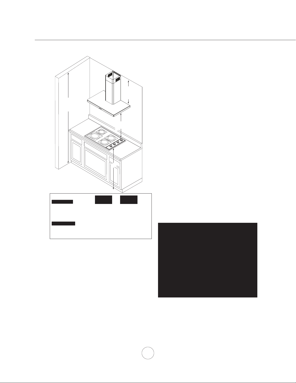
26” min.
34” max.
min. A
min. B
max. C
min. D
min. E
max. F
Standard Extension
Hood Heights Duct Cover Duct Cover
minimum ducted (A) 26 1/2” 41 1/2“
minimum recirculating (B) 31” 45 1/2“
maximum (C) 50” 80”
Ceiling Heights
minimum ducted (D) 88 1/2” (7’ 4 1/2”) 103 1/2“ (8’ 7 1/2”)
minimum recirculating (E) 93” (7’ 9”) 107 1/2“ (8’ 11 1/2”)
maximum (F) 120” (10’) 150” (12’ 6”)
36”
ALWAYS, when possible, reduce the number of
transitions and turns. If a long duct run is required,
increase duct size from 6” to 7” or 8”.
If turns or transitions are required: Install as far
away from duct opening and as far apart between
the two transitions as possible.
Minimum mount height between range top to hood
bottom should be no less than 26”.
Maximum mount height should be no higher than
34”.
It is important to install the hood at the proper
mounting height. Hoods mounted too low could
result in heat damage and re hazard; while hoods
mounted too high will be hard to reach and will
loose performance and eciency.
If available, also refer to range manufacturer’s
height clearance requirements and recommended
hood mounting height above range. Always check
your local codes for any dierences.
Installation – Mounting Height & Clearance
DUCTING
A minimum of 6” round duct must be used to
maintain maximum air ow eciency.
Always use rigid type metal ducts only. Flexible
ducts could restrict air ow by up to 50%.
Use calculation worksheet to compute total duct
work (Page 5).
Duct cover extension kit available for ceiling
heights up to 12 feet. Turn to page 19 for part
number and ordering information.
D
DAMAGE-SHIPMENT / INSTALLATION:
• Please fully inspect unit for damage before
installation.
• If the unit is damaged in shipment, return the
unit to the store in which it was bought for
repair or replacement.
• If the unit is damaged by the customer, repair
or replacement is the responsibility of the
customer.
• If the unit is damaged by the installer (if other
than the customer), repair of replacement must
be made by arrangement between customer
and installer.
6
Page 9

WARNING FIRE HAZARD
NEVER exhaust air or terminate duct work into spaces between walls, crawl spaces, ceiling, attics or garages.
All exhaust must be ducted to the outside, unless using the recirculating option.
Use single wall rigid metal ductwork only.
Fasten all connections with sheet metal screws and tape all joints w/ certied Silver Tape or Duct Tape.
Some Ducting Options
Roof Pitch w/
Flashing & Cap
ductless
recirculating
Soffit or crawl space
side wall cap
w/ gravity damper
side wall cap
w/ gravity damper
Installation – Ducting Options
7
Page 10
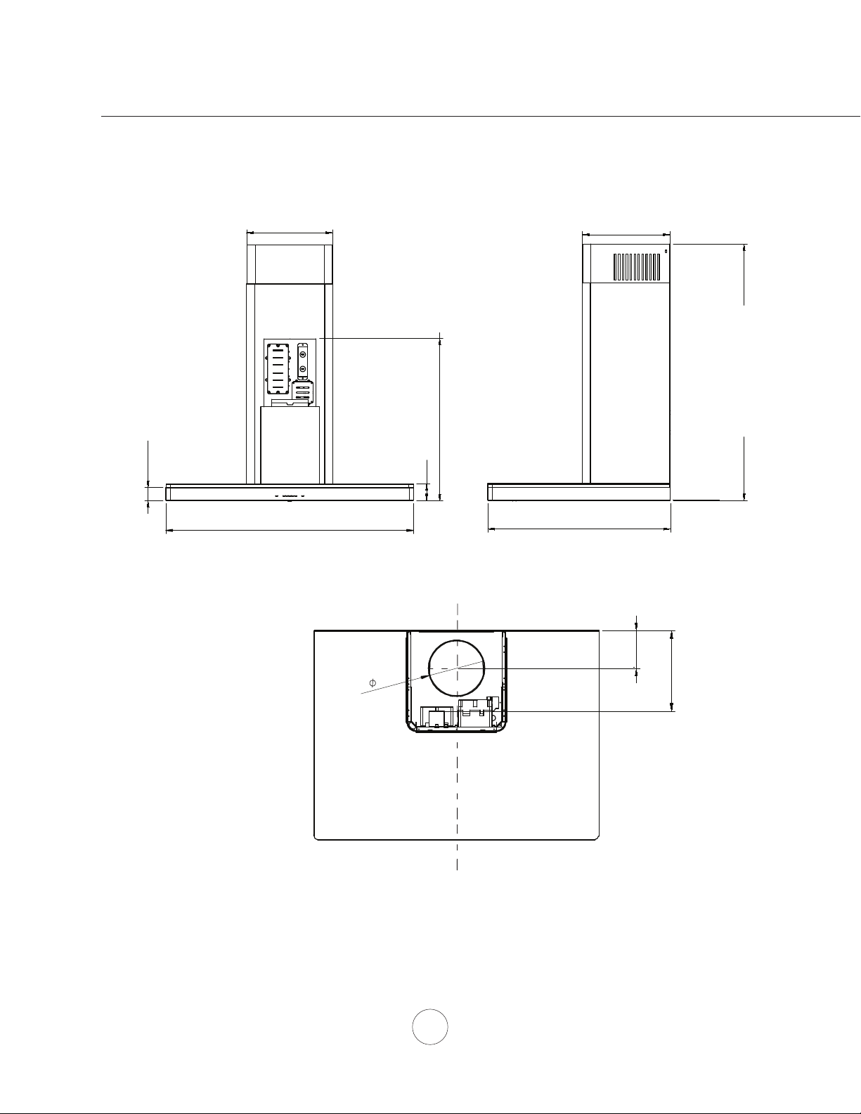
10
3/8
”
10 9/16”
”
www.zephyronline.com
STANDARD
min. ducted - 26 1/2”
min. recirc. - 31”
max. - 50”
Z1C-00LU EXTENSION
min. ducted - 41 1/2”
25 1/8”
min. recirc. - 45 1/2”
max. - 80”
1 9/16
29
15/16”, 35 7/16”
2”
22”
Installation – Hood Specication
3 15/16"
"
6
AC in
CL
8 7/16"
8
Page 11
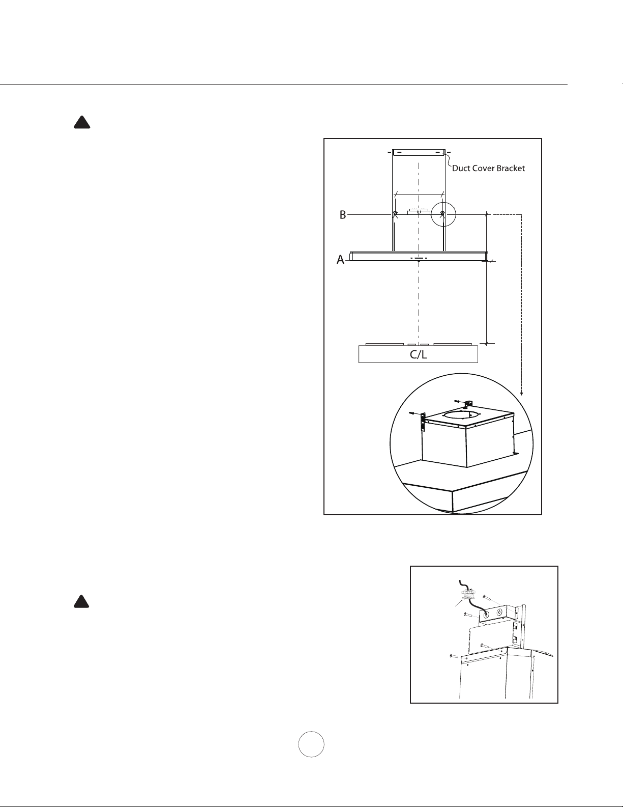
1. Measure from range top to hood bottom and mark line A.
26” min.
8-
15/16
”
14-
5/8
”
CAUTION: At least two installers are required
due to the weight and size of the hood.
!
accordance
properly grounded. Turn off electrical power at service entrance before wiring.
!
(26” minimum from range top) .
2. Plum and mark center line.
3. Mark hood height line B. (14-5/8” from line A)
4. Mark mounting spread from C/L. (8-15/16” on line B)
5. Fasten (2) M4 x 1-1/2” screws into studs on line B but
do not tighten all the way. Note: Wood blocking may
need to be added behind the drywall if no studs are
present. Wall anchors may also be used but check
local codes for compliance. Failure to use suitable
wall anchors and screws to hold the weight of the
hood could result in personal injury or damage to
the cooking surface or counter.
6. Remove tape and securing electronics mounting bracket
to hood. Reposition electronics mounting bracket as
shown in (FIG B.) and secure to motor housing using (2)
pre installed screws (FIG B-3).
6. Remove the (2) aluminum mesh lters.
7. Hang hood onto the mounting screws and hand tighten
each screw. (Fig A)
8. Center and attach duct cover mounting bracket to wall
just below the ceiling or sot using (2) M4 x 1” screws.
9. Install electrical (FIG B-2) and duct work. Seal duct work
with aluminum duct tape.
10. Power up hood and check for leaks around duct tape.
11. Place telescopic duct covers onto hood and extend
* If using hood in recirculating mode you must secure the
inner (top) duct cover upwards and secure to duct cover
bracket using (2) M4 x 8 screws. Reinstall mesh lters.
air diverter plate onto wall before installing duct work and
duct covers. You will also need to install charcoal lters
and brackets. Turn to page 10 for more details.
WARNING: Electrical wiring must be done by a qualified person(s) in
with all applicable codes and standards. This range hood must be
Installation – Mounting the Hood
FIG. A
2
1
Cable Lock
Cable Lock
A cable locking connector (not supplied) might
be required by local codes. Check with local
requirements and codes, purchase and install
appropriate connector if necessary.
9
3
Motor Housing
FIG. B
Page 12

www.zephyronline.com
2 31
Ductless recirculation is intended for applications where an exhaust duct work is not possible to be installed.
When converted, the hood functions as a recirculating hood rather than an exhaust hood. Fumes and exhaust
from cooking are drawn and ltered by a set of optional charcoal lters. The air is then puried and recirculated back within the home.
We recommend to ALWAYS exhaust air outside of the home by employing existing or installing new duct
work, if possible. The hood is most eective and ecient as an exhaust hood. Only when the exhaust option
is not possible should you recourse to converting the hood into a recirculating hood.
When converted to be a recirculating hood, a set of charcoal lters are required on top of its standard Metal
Filter set. Order according to its part number below. The standard mesh lters are intended to capture residue
from cooking and the optional charcoal lters help to purify fumes exhausted from cooking for recirculation.
RECIRCULATING KIT (REQUIRED IF NO DUCTING IS USED)
Kit includes charcoal lter and air diverter plate.
Hood Models Part No. Filters & in pkg.
ZLU ZRC-00LU 1
1. Purchase recirculating kit per the part number above
2. Secure air diverter plate to wall below duct cover bracket. Run
6” ducting from top of hood and secure to air diverter plate.
(FIG. C)
3. Remove aluminum mesh lters from hood. Install spring clip
into motor housing. Secure charcoal lter to motor housing by
spring clip.
Installation – Ductless Recirculating
4. Re-Install mesh lters. For more details refer to manual
included with recirculating kit.
5. Charcoal lters must be replaced after every 120 hours of use
(or approximately every 3 to 4 months based on an average of
1 - 2 hrs. of daily cooking time).
Charcoal Filter Replacements
Hood Model Part No. Qty to Order
ZLU Z0F-C092 1
DO NOT WASH CHARCOAL FILTERS. Charcoal lters may need
to be changed more often depending on cooking habits.
FIG. C
10
Page 13

Lights Off/Low/High
Display (speed level, delay off, filter clean/change)
Adjust 5 Speed Levels
Power / Delay Off
1 POWER / DELAY OFF BUTTON
Power Button Function
- Button will turn power on and off for entire hood (fan and lights).
- Hood will remember the last speed and light level it was turned off at.
(Example: Press Button to turn off hood when on fan speed 4 and high lights. Press Button
again and the hood will turn back on at speed 4 and high lights level.)
Delay Off Button Function
- With the fan on press and hold the Button for two seconds. The fan will change to speed 1 and the
5 minute delay off timer will start.
+ LEDs will illuminate and slowly blink in accordance with the time
remaining until the fan and lights automatically turn off.
- Pressing Button while Delay Off Function is enabled will turn the hood off and cancel the Delay Off
Function.
ACT Verification
- Airflow Control Technology (ACT) allows the installer to set the maximum fan CFM to align with local
codes and regulations.
- To verify the maximum fan CFM:
- With hood off, hold the Button for two seconds. If all five fan speed indicators illuminate =
default maximum CFM. If four fan speed indicators illuminate = 390 maximum CFM. If 3 fan
speed indicators illuminate = 290 maximum CFM.
2 SPEED SELECTION BUTTON
Fan Speed Decrease Button
- Press this button to decrease fan speed. 5, 4, 3, 2, 1.
- If fan is On Speed 1 and this button is pressed, fan will power Off.
Fan Speed Increase Button
- Press this button to increase fan speed. Fan On, 1, 2, 3, 4, 5.
- If hood is Off and this button is pressed, fan will turn On Speed 1.
Act Enabled Speed Selections
- When ACT is enabled, the number of fan speeds will be reduced as follows:
- 390 CFM = Maximum 4 speeds
- 290 CFM = Maximum 3 speeds
Lighted Glass Button
5
Features & Controls - ICON Touch Controls
11
Page 14

3 LIGHTS BUTTON
- Lights have two levels, Low and High.
- From off, press one time for Low. Press again for High. Press again to power lights off.
4 DISPLAY INDICATORS
Mesh Filter Clean Reminder (always enabled)
- After 30 hours of fan usage, the button indicator will begin to slowly blink indicating it is time to
clean the mesh filters.
- To reset: With hood off: hold the button for three seconds. All LED indicators will blink two times
confirming the 30 hour timer has been reset.
Charcoal Filter Replace Indicator (disabled by default, must be enabled if recirculating hood)
- To enable Charcoal Filter Replacement Reminder:
- With hood off, hold button and button simultaneously for two seconds. All LED indicators
will illuminate for three seconds confirming the Charcoal Filter Replace Reminder is enabled.
- To disable Charcoal Filter Replacement Reminder:
- With hood off, hold button and button simultaneously for two seconds. All LED indicators
will blink two times confirming the Charcoal Filter Replace Reminder is disabled.
- After 120 hours of fan usage the button will slowly blink indicating the charcoal filters need
replacment.
- To reset: With hood off, hold the button for two seconds. All LED indicators will blink two times
confirming the 120 hour timer has been reset.
5 LIGHTED GLASS BUTTON
- Press to cycle glass color from White, Blue, Amber and Off.
- Press and hold for 3 seconds to activate demo mode. While in demo mode each color will gradually
change every 10 seconds.
- Pressing to power off the LED lights will also power off the lighted glass.
Features & Controls - ICON Touch Controls
www.zephyronline.com
12
Page 15

SURFACE MAINTENANCE:
Do not use corrosive detergents, abrasive detergents or oven cleaners.
Do not use any product containing chlorine bleach or any product containing chloride.
Do not use steel wool or abrasive scrubbing pads which will scratch and damage surface.
Cleaning Stainless Steel
Clean periodically with warm soapy water and clean cotton cloth or micro ber cloth. Always rub in the
direction of the stainless steel grain. To remove heavier grease build up use a liquid degreaser detergent.
After cleaning use a non-abrasive stainless steel polish/cleaners, to polish and bu out the stainless luster
and grain. Always scrub lightly, with clean cotton cloth or micro ber cloth and bu in the direction of the
stainless steel grain.
Aluminum Mesh Filters
The aluminum mesh lters installed by the factory are intended to lter out residue and grease from
cooking. They need not be replaced on a regular basis but are required to be kept clean.
Remove and clean by hand or in dishwasher using a non-phosphate detergent. Discoloration of the lter
may occur if using phosphate detergents, or as a result of local water conditions - but this will not aect
lter performance. This discoloration is not covered by the warranty. Spray degreasing detergent and leave
to soak if heavily soiled.
Dry lters and re-install before using hood.
Removing Aluminum Mesh Filters
1. Pull down on lter latch to disengage lter spring
2. Pull down on lter hande to remove lter
Maintenance – Hood and Filter Cleaning
13
Page 16

LED LIGHT STRIPS
In the unlikely event that your LED strip fails, please contact Zephyr to order replacement parts.
See list of parts and accessories page for part #’s and contact information.
To replace LED light strip
1. Remove aluminum mesh lters.
2. Remove light panel by two screws.
3. Disconnect LED light strip quick connector.
4. Push in the two side clips on the ends of the LED strip.
5. Push LED light strip through the light panel opening.
Maintenance – Lights
www.zephyronline.com
14
Push the clip
Page 17

TROUBLESHOOTING PROCEDURES FOR ZLU
Issue Cause What to do
After installation,
the unit doesn’t
work.
Light works, but
blower is not
turning.
The speed levels
of the blower
sound the same.
The unit is
vibrating.
The blower is
working, but the
lights are not.
The unit turns on
by itself.
The hood is
not venting out
properly.
Mesh Filter is
vibrating.
1. The power source is not turned ON. 1. Make sure the circuit breaker and the unit’s
power is ON.
2. The power line and the cable locking connector
is not connecting properly.
3. The switch board or control board wirings are
disconnected.
4. The switch board or control board is defective. 4. Change the switch board or control board.
1. The blower is defective, possibly seized. 1. Change the blower.
2. The thermally protected system detects if the
blower is too hot to operate and shuts the blower
down.
3. Damaged capacitor. 3. Change the capacitor.
4. The switch board or control board is defective. 4. Change defective part.
1. Using the wrong size or type of ducting. 1. Change the duct size to at least 6” round or
1. The blower is not secured in place. 1. Tighten the blower in place.
2. Damaged blower wheel. 2. Replace the blower.
3. The hood is not secured in place. 3. Check the installation of the hood.
1. Defective LED bulb. 1. Change the LED bulb.
2. The LED wire connection to the control board is
disconnected.
3. The LED bulb connector is disconnected. 3. Check the LED bulb connector.
1. A spot light or kitchen lamp is shining directly
onto the switch controls.
1. The hood might be hanging to high from the
cook top.
2. The wind from the opened windows or opened
doors in the surrounding area are aecting the
ventilation of the hood.
3. Blockage in the duct opening or ductwork. 3. Remove all the blocking from the duct work or
4. The direction of duct opening is against the wind. 4. Adjust the duct opening direction.
5. Using the wrong size of ducting. 5. Change the ducting to at least 6” or higher.
1. Mesh lter is loose. 1. Change the mesh lter.
2. Check the power connection with the unit is
connected properly.
3. Make sure the wirings at the switch board and
control board are connected properly.
2. The blower will function properly after the
thermally protected system cool down.
higher and change the duct type to rigid metal
rather than exable.
2. Check the LED wire connection at the control
board.
1. The switch controls are light sensative. A
direct light source onto the switch controls
may disrupt switch functions.
1. Adjust the distance between the cook top and
the bottom of the hood within 26” and 34”
range.
2. Close all the windows and doors to eliminate
the outside wind ow.
duct opening.
Troubleshooting
15
Page 18

www.zephyronline.com
CAUTION:
Hood must be disconnected from main power prior to performing the
conversion instructions listed below. Failure to do so could result in
personal injury or damage to the product.
!
PC Board
1
3
5
7
2
4
6
8
Ju mp er 5- 6 or 7-8
DEFAULT POSITION
Default Max. Blower CFM
Ju mp er 3- 4
Max. Blower CFM
390
Ju mp er 1- 2
Jumper Pins
Plastic
Jumper
1
3
5
7
2
4
6
8
1
3
5
7
2
4
6
8
1
3
5
7
2
4
6
8
Max. Blower CFM
290
Models: ZLU
- Locate PC board box on top of blower housing.
- Remove 2 to 4 screws attaching PC board cover.
Airow Control Technology (ACT)
Some local codes limit the maximum amount of CFM a range hood can move. ACT allows you to control the
maximum blower CFM of select Zephyr Ventilation range hoods without the need for expensive make up air kits.
ACT enables the installer to easily set the maximum blower speed to one of two most commonly specied CFM
levels; 390 or 290 CFM. The usage of ACT may not be necessary for your installation. Please check your local codes
for CFM restrictions.
By default the maximum blower CFM is set to 600.
To enable ACT
ACT Conversion
1. Before hood installation, gain access to PC board by following the steps shown in FIG. J.
2. Change plastic jumper positioning as shown in FIG. K to set the desired maximum blower CFM.
3. Re-install PC board & continue with hood installation.
4. Remove the appropriate foil CFM sticker included with the hood literature and place inside the hood body below
the wiring diagram or in another clearly visible location.
NOTE: After re-positioning the jumper and powering on the hood, the CFM cannot be changed again.
To verify if your installer enabled ACT
With hood o, press and hold the power button for three seconds. If 5 LEDs illuminate = defualt max. CFM, if 4 LEDs
illuminate = max. 390 CFM, and if 3 LEDs illuminate = max. 290 CFM.
When ACT is enabled, the number of blower speeds will be reduced. 390 CFM = max. 4 speeds and 290 CFM =
max. 3 speeds.
There should also be a foil label located inside the hood body near the wiring diagram that indicates the blower CFM.
FIG. J
FIG. K
16
Page 19

Fan Curve Diagrams
17
Page 20

Fan Curve Diagrams
www.zephyronline.com
18
Page 21

ZLU-E30BS, ZLU-M90BS
CIRCUIT DIAGRAM
5A 250VA C
AC 120V
ZLU-E30BX-P
VOLTS
HZ
MAX AMPS
120 60 2.7
Wiring Diagrams
Power consumption shown for default 600 CFM blower conguration
ACT 390 CFM - Fan Max. Amps, 1.97
ACT 290 CFM - Fan Max. Amps, 1.65
19
Page 22

www.zephyronline.com
DESCRIPTION PART#
Replacement Parts
Aluminum Mesh Filter (each) 50200053
LED Light Strip, 9W Z0B0042
Optional Accessories
Recirculating Kit ZRC-00LU
Replacement Charcoal Filter (each) Z0F-C092
Extension Duct Cover Z1C-00LU
Universal Make-Up Air Damper MUA006A
To order parts, visit us online at http://store.zephyronline.com or call us at 1.888.880.8368
List of Parts & Accessories
20
Page 23

Zephyr Ventilation, LLC (referred to herein as “we” or “us”) warrants to the original consumer purchaser (referred to herein
as “you” or “your”) of Zephyr products (the “Products”) that such Products will be free from defects in materials or
workmanship as follows:
Three Year Limited Warranty for Parts: For three years from the date of your original purchase of the Products, we will
provide, free of charge, Products or parts (including LED light bulbs, if applicable) to replace those that failed due to
manufacturing defects subject to the exclusions and limitations below. We may choose, in our sole discretion, to repair or
replace parts before we elect to replace the Products.
One Year Limited Warranty for Labor: For one year from the date of your original purchase of the Products, we will
provide, free of charge, the labor cost associated with repairing the Products or parts to replace those that failed due to
manufacturing defects subject to the exclusions and limitations below. After the first year from the date of your original
purchase, you are responsible for all labor costs associated with this warranty.
Warranty Exclusions: This warranty covers only repair or replacement, at our option, of defective Products or parts and
does not cover any other costs related to the Products including but not limited to: (a) normal maintenance and service
required for the Products and consumable parts such as fluorescent, incandescent or halogen light bulbs, mesh and charcoal filters and fuses; (b) any Products or parts which have been subject to freight damage, misuse, negligence, accident,
faulty installation or installation contrary to recommended installation instructions, improper maintenance or repair (other
than by us); (c) commercial or government use of the Products or use otherwise inconsistent with its intended purpose; (d)
natural wear of the finish of the Products or wear caused by improper maintenance, use of corrosive and abrasive cleaning
products, pads, and oven cleaner products; (e) chips, dents or cracks caused by abuse or misuse of the Products; (f) service
trips to your home to teach you how to use the Products; (g) damage to the Products caused by accident, fire, floods, acts
of God; or (h) Custom installations or alterations that impact serviceability of the Products. If you are outside our service
area, additional charges may apply for shipping costs for warranty repair at our designated service locations and for the
travel cost to have a service technician come to your home to repair, remove or reinstall the Products. After the first year
from the date of your original purchase, you are also responsible for all labor costs associated with this warranty. All Products
must be installed by a qualified professional installer to be eligible for warranty repairs or service.
Limitations of Warranty. OUR OBLIGATION TO REPAIR OR REPLACE, AT OUR OPTION, SHALL BE YOUR SOLE
AND EXCLUSIVE REMEDY UNDER THIS WARRANTY. WE SHALL NOT BE LIABLE FOR INCIDENTAL,
CONSEQUENTIAL OR SPECIAL DAMAGES ARISING OUT OF OR IN CONNECTION WITH THE USE OR
PERFORMANCE OF THE PRODUCTS. THE EXPRESS WARRANTIES IN THE PRECEDING SECTION ARE
EXCLUSIVE AND IN LIEU OF ALL OTHER EXPRESS WARRANTIES. WE HEREBY DISCLAIM AND EXCLUDE ALL
OTHER EXPRESS WARRANTIES FOR THE PRODUCTS, AND DISCLAIM AND EXCLUDE ALL WARRANTIES
IMPLIED BY LAW, INCLUDING THOSE OF MERCHANTABILITY AND FITNESS FOR A PARTICULAR PURPOSE.
Some states or provinces do not allow limitations on the duration of an implied warranty or the exclusion or limitation of
incidental or consequential damages, so the above limitations or exclusions may not apply to you. To the extent that
applicable law prohibits the exclusion of implied warranties, the duration of any applicable implied warranty is limited to the
same three-year and one-year periods described above if permitted by applicable law. Any oral or written description of the
Products is for the sole purpose of identifying the Products and shall not be construed as an express warranty. Prior to
using, implementing or permitting use of the Products, you shall determine the suitability of the Products for the intended
use, and you shall assume all risk and liability whatsoever in connection with such determination. We reserve the right to
use functionally equivalent refurbished or reconditioned parts or Products as warranty replacements or as part of warranty
service. This warranty is not transferable from the original purchaser and only applies to the consumer residence where the
Product was originally installed located in the United States and Canada. This warranty is not extended to resellers.
To Obtain Service Under Limited Warranty: To qualify for warranty service, you must: (a) notify us at the address or
telephone number stated below within 60 days of the discovery of the defect; (b) give the model number and serial number;
and (c) describe the nature of any defect in the Product or part. At the time of the request for warranty service, you must
present evidence of your proof of purchase and proof of the original purchase date. If we determine that the warranty
exclusions listed above apply or if you fail to provide the necessary documentation to obtain service, you will be responsible
for all shipping, travel, labor and other costs related to the services. This warranty is not extended or restarted upon warranty
repair or replacements.
Please check our website for any additional Product information, www.zephyronline.com.
Zephyr Ventilation Service Department, 2277 Harbor Bay Parkway, Alameda, CA 94502 1-888-880-8368
Warranty
21
Page 24

www.zephyronline.com
PRODUCT REGISTRATION
Congratulations on your Zephyr range
hood purchase! Please take a moment to
register your new range hood at
www.zephyronline.com/registration
IT’S IMPORTANT
Prompt registration helps in more ways
than one.
Ensures warranty coverage should you
need service.
Ownership verification for insurance
purposes.
Notification of product changes or recalls.
Zephyr Ventilation | 2277 Harbor Bay Pkwy. | Alameda, CA 94502 | 1.888.880.8368
22
Page 25

Luce
ZLU-E30BS
ZLU-M90BS
www.zephyronline.com
Guide d’utilisation, d’entretien et d’installation
Numéro de modèle :
Numéro de série :
AUG20.0301 © Zephyr Ventilation, LLC.
Page 26

www.zephyronline.com
Page 27

MISE EN GARDE DE SÉCURITÉ......................................................................................... 2-3
LISTE DU MATÉRIEL....................................................................................................................... 4
INSTALLATION
Feuille de calcul pour le conduit...............................................
Espace libre et hauteur de montage................................
Options d’installation pour le conduit.
.................................................................................. 7
Spécications de la hotte...............................................................
Montage de la hotte.......................................................................
Recirculation d’air sans conduit...............................................................
................................ 5
........................................... 6
......................... 8
......................... 9
............. 10
COMMANDES ET CARACTÉRISTIQUES
ICON Commandes ...........................................................................
...................... 11-12
ENTRETIEN
Nettoyage de la hotte et des ltres ....................................................
Bandes lumineuses à LED............ ....................................................
..................... 13
..................... 14
DÉPANNAGE...................................................................................................................
CONVERSION DE LA ACT..............................................................................................
DIAGRAMMES DES COURBES CARACTÉRISTIQUES DES VENTILATEURS
............... 17-18
Table des matières
15
16
SCHÉMA DE CÂBLAGE
............................................................................................................................ 19
LISTES DES ACCESSOIRES ET DES PIÈCES..............................................................
GARANTIE......................................................................................................................
ENREGISTREMENT DU PRODUIT.................................................................................
1
20
21
22
Page 28

LISEZ ET CONSERVEZ CES INSTRUCTIONS
www.zephyronline.com
AVERTISSEMENT
POUR RÉDUIRE LES RISQUES D’INCENDIE OU DE DÉCHARGE ÉLECTRIQUE, N’UTILISEZ PAS CET APPAREIL AVEC UN TABLEAU
DE COMMANDE À SEMI-CONDUCTEURS.
AVERTISSEMENT
POUR RÉDUIRE LES RISQUES D’INCENDIE, DE DÉCHARGE ÉLECTRIQUE OU DE BLESSURE, RESPECTEZ CES CONSIGNES :
a. N’utilisez cet appareil que de la manière prévue par le fabricant. Si vous avez des questions, communiquez avec le fabricant.
b. Avant de procéder au nettoyage ou à l’entretien de l’appareil, éteignez l’alimentation du panneau électrique et bloquez le dispositif de
déconnexion pour éviter que l’alimentation électrique ne soit accidentellement rallumée. Si le dispositif de sectionnement d’électricité ne peut
être bloqué, attachez un avertissement (comme une étiquette) bien en vue sur le tableau électrique.
ATTENTION
Pour ventilation générale seulement. N’utilisez pas cet appareil pour évacuer des vapeurs et des matériaux explosifs ou dangereux. Prenez garde
lors de l’utilisation d’agents nettoyants ou de détergents. Ne devrait être utilisé que dans la cuisine de votre maison.
AVERTISSEMENT
POUR RÉDUIRE LES RISQUES DE FEU DE GRAISSE SUR LA SURFACE DE CUISSON :
a. Ne laissez jamais l’appareil sans surveillance lors de son utilisation à haute température. Les débordements par bouillonnement causent de la
fumée et des déversements de graisse qui peuvent prendre feu. Faites chauer l’huile à des températures basses ou moyennes.
b. Allumez toujours la hotte lorsque vous cuisinez à haute température ou que vous faites amber des aliments.
c. Nettoyez fréquemment les ventilateurs de la hotte. La graisse ne devrait jamais s’accumuler dans les ventilateurs ou les ltres.
d. Utilisez des poêlons aux dimensions adéquates. Utilisez toujours une batterie de cuisine correspondant aux dimensions de l’élément.
Mise en garde de sécurité
e. Assurez-vous que le ventilateur, les ltres et les surfaces où la graisse pourrait s’accumuler sont toujours propres.
f. Utilisez le réglage haut de la hotte seulement lorsque nécessaire.
g. Ne laissez pas la hotte sans surveillance lorsque vous cuisinez.
h. Utilisez toujours une batterie de cuisine et des ustensiles convenant au type et à la quantité de nourriture que vous préparez.
AVERTISSEMENT
POUR RÉDUIRE LES RISQUES DE BLESSURE LORS D’UN INCENDIE SUR LA SURFACE DE CUISSON :
a. ÉTOUFFEZ LES FLAMMES avec un couvercle, une plaque à biscuits ou un plateau de métal et éteignez ensuite le brûleur. PRENEZ GARDE
AUX RISQUES DE BRÛLURE. Si les ammes ne disparaissent pas, ÉVACUEZ LES LIEUX ET APPELEZ LE SERVICE D’INCENDIE.
b. NE PRENEZ JAMAIS UN POÊLON EN FEU – Vous pourriez vous brûler.
c. N’UTILISEZ PAS D’EAU, ou un linge à vaisselle mouillé – une violente explosion de vapeur s’ensuivra.
d. Utilisez un extincteur SEULEMENT si :
1. Vous savez que vous possédez un extincteur de classe ABC et vous savez vous en servir.
2. Le feu est faible et ne s’est pas répandu depuis son point d’origine.
3. Vous avez appelé le service d’incendie.
4. Vous pouvez sortir facilement de l’endroit où vous combattez le feu.
AVERTISSEMENT
POUR RÉDUIRE LES RISQUES D’INCENDIE, DE DÉCHARGE ÉLECTRIQUE OU DE BLESSURE, SUIVEZ LES CONSIGNES SUIVANTES :
a. Les travaux d’installation et de câblage électrique doivent être faits par une personne qualiée selon les stipulations de tous les normes et
standards en vigueur, dont les normes des constructions ayant une cote de résistance au feu.
b. Pour prévenir les contre-explosions, une certaine quantité d’air est nécessaire pour la combustion et l’évacuation des gaz par le carneau
(cheminée) de l’appareil de combustion. Respectez les directives du fabricant d’outillage de chauage et les normes de sécurité comme celles
publiées par la NFPA (Association nationale des services d’incendie), par la Société américaine des ingénieurs en chauage, réfrigération et
climatisation (ASHRAE) et par les normes des autorités locales.
c. Lorsque vous coupez ou percez un mur ou un plafond, assurez-vous de ne pas endommager le câblage électrique ou toute autre installation
technique dissimulée.
d. Les ventilateurs canalisés doivent toujours évacuer l’air à l’extérieur.
e. N’installez JAMAIS un interrupteur à une distance atteignable depuis un bain ou une douche.
f. Assurez-vous que l’alimentation électrique est éteinte avant de procéder à l’installation, au câblage ou à l’entretien de l’appareil
2
Page 29

ATTENTION
www.P65Warnings.ca.gov
POUR RÉDUIRE LES RISQUES D’INCENDIE, N’UTILISEZ QUE DES CONDUITS D’AÉRATION EN MÉTAL.
ATTENTION
Pour réduire les risques d’incendie et pour évacuer l’air convenablement, assurez-vous de canaliser l’air à l’extérieur de
la maison. N’installez pas l’échappement du conduit dans les espaces entre les murs, le plafond, le grenier, les vides
sanitaires ou le garage.
Cet appareil n’est pas conçu pour être utilisé à l’extérieur.
FONCTIONNEMENT
Laissez toujours les grilles de sûreté et les ltres en place. Sans ces éléments, les ventilateurs en marche pourraient
accrocher des cheveux, des doigts ou des vêtements amples.
Le fabricant se dégage de toute responsabilité dans les cas de non-respect des instructions transmises dans le présent
manuel pour l’installation, l’entretien et l’utilisation adéquate du produit. Le fabricant se dégage également de toute
responsabilité pour des blessures qui résulteraient de la négligence lors de l’utilisation. De plus, la garantie prend n
automatiquement lors de l’entretien inapproprié de l’appareil.
*NOTE : Veuillez vérier les actualisations du produit sur le site Web www.zephyronline.com avant de procéder à
des travaux.
EXIGENCES ÉLECTRIQUES
Important :
Respectez tous les codes et règlements en vigueur.
Il est de la responsabilité du client de :
- Communiquer avec un installateur-électricien qualié.
- S’assurer que l’installation électrique est adéquate et qu’elle respecte le Code national de l’électricité, la plus récente
édition* du ANSI/NFPA 70 ou des normes du CSA C22.1-94, le Code canadien de l’électricité, section 1, la plus récente
édition** du code C22.2 No.0-M91 ainsi que tous les codes et réglements en vigueur.
Si les codes permettent l’utilisation d’un l de garde isolé et que vous en utilisez un, il est recommandé qu’un électricien
qualié détermine si le cheminement du l est adéquat.
N’eectuez pas la mise à la terre à un tuyau de gaz.
Demandez à un électricien qualié si vous n’êtes pas certain que la hotte a été mise à la terre adéquatement.
N’introduisez aucun fusible dans le circuit neutre ou de mise à la terre.
*National Fire Protection Association Batterymarch Park, Quincy, Massachusetts 02269
** CSA International 8501 East Pleasant Valley Road, Cleveland, Ohio 44131-5575
Cet appareil requiert une alimentation électrique de 120V 60Hz. Il doit être connecté à un circuit terminal individuel
dûment mis à la terre, protégé par un disjoncteur de circuit ou un fusible temporisé de 15 ou 20 ampères. Le câblage doit
compter 2 ls avec mise à la terre. Veuillez vous référer au Diagramme électrique étiqueté sur l’appareil.
Un raccord de câble (non inclus) pourrait également être exigé par les normes et réglementations locales. Informez-vous
des exigences et des normes locales. Achetez et installez le connecteur approprié si nécessaire.
ZLU-E30BS / ZLU-M90BS - 321 Watts, 2.7 Ampères
Mise en garde de sécurité
La consommation énergétique indiquée ci-dessus s’applique aux spécications par défaut. Les hottes de Zephyr dont la
technologie de contrôle du débit d’air (TCDA) est activée consomment moins d’énergie. Consultez le schéma de câblage
à la n du manuel pour obtenir de plus amples renseignements.
Prop. 65 Avertissement pour les résidents californiens
AVERTISSEMENT:
Cancer et troubles de l’appareil reproducteur
3
Page 30

(3) Capuchons de
connexion
(2) M4 x 1”
(2) M4 x 8
PIÈCES NON FOURNIES
- Conduit et tous les outils d’installation
- Raccord de câble (si exigé par les codes en vigueur)
- Accessoire – prolongement pour recouvrement de conduit - Z1C-00LU
- Accessoire – recirculation d’air - ZRC-00LU
CONTENU DE LA TROUSSE DE QUINCAILLERIE
PIÈCES FOURNIES
MODÈLES : ZLU-E30BS , ZLU-M90BS
1 - Hotte avec ventilateur interne
1 - Support mural pour le recouvrement de conduit
1 - Ensemble de recouvrement de conduit (parties supérieure et inférieure)
1 - Registre antirefoulement circulaire de 6" (préinstallé)
1 - 9W BriteStrip™ DEL
2 - Filtres à tamis en aluminium
1 - Trousse de quincaillerie
(3) M4 x 1-1/2”
Liste du matériel
www.zephyronline.com
4
Page 31

To tal
=
3- 1/ 4” x 10”
1 pi x ( ) =
pi
5 pi x ( ) =
pi
20 pi x ( ) =
pi
6”, 7”, 8”, 10”
15 pi
x ( ) =
pi
6”, 7”, 8”, 10”
9 pi x ( ) =
pi
pi
6”, 7”, 8”, 10”
1 pi x ( ) =
pi
To tal
=
6”, 7”, 8”, 10”
30 pi x ( ) =
pi
pi
pi
pi
6”, 7”, 8”, 10”
30 pi x ( ) =
pi
1 pi x ( ) =
pi
16 pi x ( ) =
pi
8 pi x ( ) =
pi
23 pi x ( ) =
pi
7” to 6” or
8” to 7” circ.
reducteur
conique
25 pi x ( ) =
pi
3- 1/ 4” x 10”
15 pi x ( ) =
pi
3- 1/ 4” x 10”
9 pi x ( ) =
pi
3- 1/ 4” x 10”
24 pi x ( ) =
pi
30 pi x ( ) =
pi
pi x ( ) =
pi
15
6”, 7“, 8”
circ.
bouchone de
l’air
Pièces de conduit
Longueur x
Nombre utilisé
rect., droit
circ., droit
rect.,
coude à 90º
rect.,
coude à 45º
rect.,
coude plat
à 90º
circ.,
coude à 90º
coude à 45º
Sous-total - colonne 1=
Longueur maximale du conduit d’aération :
Pour un mouvement d’air convenable, la longueur totale d’un conduit
d’aération ne devrait pas compter plus que l’équivalent de 100 pieds.
Pièces de conduit
Longueur x
Nombre utilisé
6” circ. à
rect. de
3-1/4" x 10",
coude à 90º
6” circ. à
rect. de
3-1/4" x 10"
6” circ. à
rect. de
3-1/4" x 10"
6” circ. à
rect. de
3-1/4" x 10",
coude à 90º
7” circ. à
rect. de
3-1/4" x 10"
7” circ. à
rect. de
3-1/4" x 10",
coude à 90º
3-1/ 4” x 10”
embout mural
rect./registre
embout
mural
circ./registre
chapeau de
toiture circ.
Sous-total - colonne 2 =
Sous-total - colonne 1 =
Total du conduit =
Installation – Feuille de calcul pour le conduit d’aération
5
Page 32

www.zephyronline.com
26” min.
34” max.
min. A
min. B
max. C
min. D
min. E
max. F
36”
Recouvrement de Prolongement de
Hauteur de la hotte conduit standard rec. de conduit
min. avec conduit (A) 26 1/2” 41 1/2“
min. avec recirc. d’air (B) 31” 45 1/2“
maximum (C) 50” 80”
Hauteur de plafond
min.avec conduit (D) 88 1/2” (7’ 4 1/2”) 103 1/2“ (8‘7 1/2’’)
min. avec recirc. d’air (E) 93” (7’ 9”) 107 1/2“ (8’ 11 1/2”)
maximum (F) 120” (10’) 150” (12’ 6”)
Lorsqu’il possible de le faire, diminuez TOUJOURS le
nombre de pièces et de changements de direction. Si un
long tronçon de conduit est nécessaire, augmentez le
diamètre du conduit de 6” à 7” ou 8”.
Si des changements de direction ou des adaptateurs
sont nécessaires, installez-les le plus loin possible de
l’ouverture et le plus éloigné possible l’un de l’autre.
La hauteur de montage minimale ne devrait pas être
moins de 26”.
La hauteur de montage maximale ne devrait pas
outrepasser 34”.
Il est important d’installer la hotte à la hauteur de montage
adéquate. Les hottes installées trop basses pourraient
être endommagées par la chaleur en plus de présenter
des risques d’incendie plus élevés tandis que les hottes
installées trop hautes seront diciles à atteindre et verront
leur ecacité et leur rendement réduits.
Si elles sont disponibles, consultez les exigences de
hauteur d’espace libre requise par le fabricant de la
cuisinière ainsi que la hauteur recommandée de montage
de la hotte au-dessus de la surface de cuisson. Informezvous toujours des normes et des réglementations locales
en vigueur pour toute diérence par rapport aux normes
du fabricant.
CONDUIT D’AÉRATION
Un conduit circulaire de 6” doit être utilisé pour
assurer une circulation d’air maximale.
Installation – Espace libre et hauteur de montage
N’utilisez que des conduits en métal rigide. Les
conduits souples pourraient réduire la circulation
d’air jusqu’à 50 %.
Utilisez la feuille de calcul pour obtenir la longueur
totale du conduit (page 5).
Ensemble de recouvrement de conduit disponible pour les
plafonds atteignant 12 pieds. Nº de pièce et information
pour commander disponibles à la page 20.
ENDOMMAGEMENT LORS DE LA LIVRAISON/
INSTALLATION:
• Veuillez vous assurer que toutes les pièces
de l’appareil ne sont pas endommagées avant
l’installation.
• Si l’appareil est endommagé durant la livraison,
retournez l’appareil à l’endroit où vous l’avez acheté
pour réparation ou remplacement.
• Si l’appareil est endommagé par le client, la réparation
ou le remplacement est à la charge du client.
• Si l’appareil est endommagé par l’installateur (si autre
que le client), le client et l’installateur doivent en venir
à une entente pour la réparation ou le remplacement.
6
Page 33

AVERTISSEMENT DE RISQUE D’INCENDIE
N’évacuez ou ne terminez JAMAIS l’échappement du conduit dans les espaces entre les murs, les vides
sanitaires, le plafond, le grenier, ou le garage. Tous les échappements doivent être dirigés à l’extérieur de la
maison, à moins que l’option de recirculation d’air ne soit utilisée.
N’utilisez que des conduits en métal pour cloison simple.
Fixez toutes les pièces du conduit avec des vis à tôle et isolez tous les joints avec du ruban adhésif en toile ou
du ruban réecteur certié.
Quelques options pour le conduit d’aération
Pente de la toiture
avec solin et chapeau
Recirculation
d’air sans conduit
Bouche d’aération
de mur latéral avec
clapet antirefoulement
Retombée de plafond ou vide sanitaire
Installation – Options pour le conduit d’aération
Bouche d’aération de
mur latéral avec clapet
antirefoulement
7
Page 34

www.zephyronline.com
1 9/16”
10
3/8”
29
15/16”, 35 7/16”
10 9/16”
STANDARD
min. avec conduit - 26 1/2”
min. avec recirculation d’air - 31”
max. - 50”
Z1C-00LU EXTENSION
min. avec conduit - 41 1/2”
25 1/8”
2”
22”
min. avec recirculation d’air - 45
1/2”
max. - 80”
3 15/16"
"
Installation – Spécications de la hotte
6
Entrée élec.
LC
8 7/16"
8
Page 35

ATTENTION : Compte tenu du poid
s
et des dimensions de la hotte, au moin
deux installateurs sont nécessaires
!
AVERTISSEMENT : Le câblage électrique doit être réalisé par une
personne qualifiée en conformité avec tous les codes et toutes les normes
en vigueur. Cette hotte doit être mise à la terre convenablement. Coupez
l’alimentation électrique du panneau électrique avant de procéder au câblage.
!
s
.
1. Prenez la mesure entre la surface de la cuisinière et la base de la
hotte; marquez la ligne A (min. 26” à partir du dessus de la cuisinière).
2. Marquez la ligne centrale avec exactitude.
3. Marquez la ligne de hauteur de montage B (à 14-5/8” de la ligne A).
4. Marquez la largeur de montage à partir de la L/C (8-15/16”).
5. Fixez (2) vis M4 x 1-1/2” aux poutres de la ligne B. Ne tournez pas
les vis jusqu’au fond. Note : Vous pourriez avoir à ajouter des
renforcements de bois derrière la cloison sèche si aucune
poutre n’est présente. Des dispositifs d’ancrage au mur peuvent
également être utilisés, mais vériez d’abord les réglementations
locales avant d’utiliser de tels dispositifs. Le fait de ne pas
utiliser des ancrages muraux et des vis convenables pour
soutenir le poids de la hotte pourrait entraîner des blessures ou
endommager la surface de cuisson ou le comptoir.
6. Enlevez le ruban qui retient le support de montage des composantes
électroniques à la hotte. Placez le support de montage des
composantes électroniques comme illustré sur la FIG. B et xez le
boîtier du moteur en place à l’aide des deux (2) vis préinstallées (FIG.
B-3).
7. Enlevez les deux (2) ltres à tamis en aluminium.
8. Suspendez la hotte aux vis de montage et serrez-les à la main (FIG.
A).
9. Centrez et xez à l’aide de (2) vis M4 x 1” le support de montage du
recouvrement de conduit au mur juste en dessous du plafond ou de la
retombée de plafond.
10.Procédez à l’installation des composantes électriques (FIG. B-2) et
du conduit. Scellez le conduit avec du ruban à conduit en aluminium.
11.Allumez la hotte et assurez-vous qu’il n’y a pas de fuites autour du
ruban à conduit.
12.Fixez les plaques de recouvrement coulissantes du conduit à la hotte et
faites glisser la plaque de recouvrement intérieure (partie supérieure) vers
le haut. Fixez-la au support de xation du recouvrement de conduit à l’aide
de deux (2) vis M3.5 x 8”. Réinstallez les ltres à tamis.
* Si vous utilisez le mode de reprise d’air, vous devez xer la plaque
du déecteur d’air au mur avant d’installer le conduit et les pièces de
recouvrement du conduit. Vous aurez également à installer des ltres à
charbon et des supports. Consultez la page 10 pour obtenir plus de détails.
8-
15/16
FIG. A
Support pour le
recouvrement du conduit
”
5/8
14-
26” min.
2
Raccord de câble
”
Installation – Montage de la hotte
1
Raccord de câble :
Un raccord de câble (non inclus) pourrait également être exigé
par les normes et réglementations locales. Informez-vous
des exigences et des normes locales. Achetez et installez le
connecteur approprié si nécessaire.
9
3
Boîtier du
ventilateur
FIG. B
Page 36

www.zephyronline.com
2 31
La conguration de reprise sans conduit a été conçue pour les applications où il est impossible d’installer un conduit
d’aération. Lorsque transformée, la hotte fonctionne comme une hotte de recirculation d’air plutôt que comme un
système d’évacuation d’air. Les vapeurs et fumées de cuisson sont aspirées et ltrées par un ensemble optionnel de
ltres à charbon. L’air est ensuite purié et redirigé à l’intérieur de la maison.
Nous recommandons de TOUJOURS évacuer l’air à l’extérieur de la maison en utilisant le conduit en place ou, s’il y
a possibilité, en installant un nouveau conduit. La hotte est plus ecace lorsqu’utilisée comme système d’évacuation
d’air. Vous ne devriez recourir à la conguration de recirculation d’air que lorsqu’il est impossible d’installer un
conduit d’aération.
Lorsque la conguration de recirculation d’air est choisie, un ensemble de ltres à charbon doit être installé sur
l’ensemble de ltres à tamis standards. Commandez-les en vous référant au numéro de pièce ci-dessous. Les ltres
à tamis standards sont conçus pour capturer les résidus de cuisson et les ltres à charbon optionnels aident à la
purication des vapeurs et fumées de la cuisson lors de la recirculation d’air.
TROUSSE DE RECIRCULATION D’AIR (REQUIS SI AUCUN CONDUIT N’EST UTILISÉ)
L’ensemble comprend des ltres à charbon et un déecteur d’air.
Modèle de hotte Numéro de pièce Filtres par paquet
ZLU ZRC-00LU 1
1. Procurez-vous l’ensemble de recirculation d’air en utilisant le
numéro de pièce ci-dessus.
2. Fixez le déecteur au mur, sous le support mural de recouvrement
de conduit. Installez le conduit de 6” à la partie supérieure de la
hotte et xez-le à la plaque du déecteur d’air (FIG. C).
3. Retirez les ltres à tamis en aluminium de la hotte. Fixez le ltre à
charbon aux attaches du boîtier du ventilateur, puis à l’aide de vis
à travers les attaches.
4. Réinstallez les ltres à tamis. Pour obtenir de plus amples
renseignements, consultez le manuel de la trousse de
recirculation d’air.
5. Les ltres à charbon doivent être remplacés après 120 heures
d’utilisation (ou approximativement tous les 3-4 mois à raison de
1-2 heures d’utilisation quotidienne).
Installation – Recirculation d’air sans conduit
Filtres à charbon de remplacement
Modèle de hotte Numéro de pièce Qtée à commander
ZLU Z0F-C092 1
NE NETTOYEZ PAS LES FILTRES À CHARBON. Vous pourriez
avoir à changer les ltres à charbon plus souvent selon vos habitudes
culinaires.
10
FIG.C
Page 37

Lumières: éteint / faible / élevé
Afficheur (vitesse, arrêt à retardement, nettoyage/changement des filtres)
Choix de 5 vitesses
Mise en marche/Arrêt
à retardement
1 MISE EN MARCHE/ARRÊT À RETARDEMENT
Fonction de la touche de mise en marche
- La touche permet d’allumer et d’éteindre toutes les fonctions de la hotte (ventilateurs et lumières).
- La hotte se rappelle la dernière vitesse et le dernier niveau d’éclairage utilisés.
(Exemple : Appuyez sur la touche lorsque le ventilateur fonctionne à la vitesse 4 et que les
lumières sont allumées à haute intensité. Si vous appuyez de nouveau sur la touche , le ventilateur repart à la vitesse 4 et les lumières se rallument à haute intensité.)
Fonction de la touche d’arrêt à retardement
- Lorsque le ventilateur est en cours d’utilisation, appuyez sur la touche et maintenez-la enfoncée
pendant deux secondes. Le ventilateur passe à la vitesse 1 et le compte à rebours de la minuterie de
l’arrêt à retardement commence.
Les DEL et s’illuminent et clignotent lentement en fonction du temps qu’il
reste avant l’arrêt automatique du ventilateur et des lumières.
- Appuyez sur la touche lorsque la fonction d’arrêt à retardement est en cours d’utilisation pour
éteindre la hotte et annuler la fonction d’arrêt à retardement.
Vérification de la TCDA
- La technologie de contrôle du débit d’air permet à l’installeur d’ajuster la quantité maximale d’évacuation de pi /min du ventilateur afin de respecter les codes et règlements en vigueur.
- Pour vérifier la quantité maximale d’évacuation de pi /min du ventilateur :
- Lorsque la hotte est éteinte, appuyez sur la touche et maintenez-la enfoncée pendant
deux secondes. Si cinq icônes de ventilateur s’illuminent, le réglage est ajusté au maximum.
Si quatre icônes s’illuminent, le maximum est de 390 pi /min. Si trois icônes s’illuminent, le
maximum est de 290 pi /min.
2 TOUCHE DE CHOIX DE VITESSE
Touche de réduction de vitesse du ventilateur
- Appuyez sur cette touche pour réduire la vitesse du ventilateur. 5, 4, 3, 2, 1.
- Si le ventilateur est à la vitesse 1 et que vous appuyez sur cette touche, le ventilateur s’éteint.
Touche d’augmentation de vitesse du ventilateur
- Appuyez sur cette touche pour augmenter la vitesse du ventilateur. 1, 2, 3, 4, 5.
- Si le ventilateur est éteint et que vous appuyez sur cette touche, le ventilateur s’allume à la vitesse 1.
Choix de vitesse avec TCDA activée
- Lorsque la TCDA est activée, le nombre de vitesses du ventilateur est réduit comme suit :
- 390 pi /min = 4 vitesses maximum
- 290 pi /min = 3 vitesses maximum
Touche d’illumination
du verre
5
3
3
3
3
3
3
Commandes - ICON Commandes à eeurement
11
Page 38

www.zephyronline.com
3 TOUCHE DE CONTRÔLE DES LUMIÈRES
- Les lumières ont deux niveaux, bas et haut.
- De off, appuyez une fois pour bas. Appuyez à nouveau pour haut. Appuyez à nouveau pour éteindre
les lumières.
4 AFFICHEUR
Rappel de nettoyage des filtres à tamis (toujours activé)
- Après 30 heures d’utilisation du ventilateur, l’icône commence à clignoter lentement, indiquant
qu’il est temps de nettoyer les filtres à tamis.
- Pour réinitialiser : Lorsque la hotte est éteinte : tenez la touche enfoncée pendant trois
secondes. Tous les indicateurs DEL clignotent deux fois, confirmant la réinitialisation de la minuterie
de 30 heures.
Indicateur de remplacement des filtres à charbons (désactivé par défaut, doit être activé lors de
l’utilisation du mode de recirculation d’air)
- Pour activer le rappel de remplacement des filtres à charbon :
- Lorsque la hotte est éteinte, tenez les touches et enfoncées simultanément pendant
deux secondes. Tous les indicateurs DEL s’illuminent pendant trois secondes, confirmant
l’activation du rappel de remplacement des filtres à charbon.
- Pour désactiver le rappel de remplacement des filtres à charbon :
- Lorsque la hotte est éteinte, tenez les touches et enfoncées simultanément pendant
deux secondes. Tous les indicateurs DEL clignotent deux fois, confirmant la désactivation du
rappel de remplacement des filtres à charbon.
- Après 120 heures d’utilisation du ventilateur, la touche clignote lentement, indiquant que les filtres
à charbon doivent être remplacés.
- Pour réinitialiser : Lorsque la hotte est éteinte : tenez la touche enfoncée pendant deux
secondes. Tous les indicateurs DEL clignotent deux fois, confirmant la réinitialisation de la minuterie
de 120 heures.
5 TOUCHE D’ILLUMINATION DU VERRE
- Appuyez sur cette touche pour illuminer le verre en blanc, bleu, jaune et pour l’éteindre.
- Appuyez sur cette touche pendant trois secondes pour activer le mode démo. Lorsque ce mode est
activé, les couleurs changent graduellement toutes les dix secondes.
- Lorsque vous appuyez sur pour allumer les ampoules DEL, l’illumination du verre s’éteint
automatiquement.
Commandes – ICON Commandes à eeurement
12
Page 39

ENTRETIEN DES SURFACES
Nettoyez régulièrement les surfaces de la hotte avec de l’eau savonneuse chaude et un chion de
coton propre. N’utilisez pas de détergent abrasif ou corrosif, de laines d’acier ou de tampons à récurer;
ils égratigneront et endommageront les surfaces.
Pour les taches plus tenaces, utilisez du produit dégraissant liquide.
Après le nettoyage, vous pouvez polir les surfaces avec des produits de polissage à acier inoxydable
non abrasifs pour redonner de l’éclat et du lustre aux surfaces. Frottez toujours doucement, avec un
chion de coton propre, et dans le sens du grain.
N’utilisez pas de produits à blanchir au chlore ou d’agents nettoyants « orange ».
Filtre à tamis en aluminium
Les ltres à tamis en aluminium installés par le fabricant ont pour fonction de ltrer les résidus et la
graisse de cuisson. Ils ne nécessitent aucun remplacement sur une base régulière, mais doivent être
gardés propres.
Enlevez-les et nettoyez-les à la main ou au lave-vaisselle avec de l’eau tiède. Vaporisez avec du
détergent pour graisse et laissez tremper pour éliminer la saleté accumulée.
Séchez les ltres et réinstallez-les avant d’utiliser la hotte.
Pour enlever les ltres à tamis en aluminium
1. Tirez le loquet du ltre vers le bas pour libérer le ressort du ltre.
2. Tirez la poignée du ltre vers le bas pour l’enlever.
Entretien – Nettoyage de la hotte et des ltres
13
Page 40

www.zephyronline.com
Bandes de lumière LED
Dans l’éventualité peu probable d’une défaillance de votre bande de LED, veuillez contacter Zephyr pour
commander des pièces de rechange.
Voir la liste des pièces et accessoires à la page pour les références et les coordonnées.
Pour remplacer la bande lumineuse à LED
1. Retirez les ltres à mailles en aluminium.
2. Retirez le panneau d’éclairage à l’aide de deux vis.
3. Débranchez le connecteur rapide du bandeau lumineux à LED.
4. Appuyez sur les deux clips latéraux situés aux extrémités de la bande de LED.
5. Poussez le ruban lumineux à travers l’ouverture du panneau lumineux.
Maintenance - Lumières
14
Push the clip
Page 41

PROCÉDURES DE DÉPANNAGE POUR LA HOTTE ZLU
Problème Cause Solution
Après l’installation,
l’appareil ne
fonctionne pas.
Les lumières
fonctionnent, mais
le ventilateur ne
tourne pas.
L’appareil vibre. 1. Le moteur n’est pas bien xé en place 1. Fixez solidement le moteur en place
Le moteur
fonctionne, mais
pas les lumières.
1. Le bloc d’alimentation n’est pas allumé 1. Assurez-vous que l’alimentation du disjoncteur et de
l’appareil est allumée
2. La ligne électrique et le raccord de câble ne sont pas
correctement branchés
3. Les ls électriques du tableau de contrôle et de
commande sont débranchés
4. Tableau de contrôle/commande défectueux 4. Remplacez le tableau de contrôle/commande
1. Le ventilateur est défectueux, possiblement bloqué 1. Remplacez le ventilateur
2. Le système de protection thermale détecte que le
moteur est trop chaud pour fonctionner et l’éteint.
3. Le condensateur est endommagé 3. Remplacez le condensateur.
4. Tableau de contrôle/commande défectueux 4. Remplacez la pièce défectueuse
2. La roue du ventilateur est endommagée 2. Remplacez le ventilateur
3. La hotte n’est pas bien xée en place 3. Vériez l’installation de la hotte
1. L’ampoule DEL est défectueuse 1. Remplacez l’ampoule DEL
2. Le câble de l’ampoule DEL est débranché du tableau
de commande.
3. Le connecteur de l’ampoule DEL est débranché. 3. Vériez la connexion de l’ampoule DEL.
2. Vériez que le branchement de l’appareil a été fait
correctement
3. Assurez-vous que les ls électriques entre les
tableaux de contrôle et de commande sont branchés
convenablement
2. Le moteur fonctionnera normalement lorsque le
système de protection thermale aura refroidi
2. Vériez la connexion des câbles de l’ampoule DEL
du tableau de commande.
Dépannage
Le ventilateur
s’allume seul
Les diérentes
vitesses du
ventilateur
semblent toutes les
mêmes.
La hotte ne
fonctionne pas
bien.
Le ltre en métal
vibre.
1. Une lumière ou lampe de la cuisine éclaire directement
le tableau de commande.
1. Vous n’utilisez pas le bon diamètre de conduit. 1. Installez un conduit circulaire d’au moins 6” et
1. La hotte est possiblement installée trop haut par rapport
à la cuisinière
2. Du vent provenant d’une fenêtre ou d’une porte ouverte
avoisinante nuit à la ventilation
3. L’ouverture du conduit ou le conduit lui-même est
bloqué
4. L’ouverture du conduit est contre le vent 4. Ajustez l’orientation de l’ouverture du conduit
5. Mauvaises dimensions de conduit d’aération 5. Remplacez le conduit par un conduit adéquat de 8”
1. Le ltre en métal est desserré 1. Assurez-vous que les attaches métalliques de la
1. Le tableau de commande est sensible à la lumière
Une source de lumière directe sur le tableau
de commande peut perturber les fonctions des
interrupteurs.
changez le type de conduit pour en utiliser un qui est
rigide, et non souple.
1. Ajustez la distance entre la surface de la cuisinière et
la base de la hotte entre 26” et 34”
2. Fermez toutes les portes et fenêtres pour éliminer
les courants d’air
3. Fermez toutes les portes et fenêtres pour éliminer
les courants d’air
ou plus.
poignée ne sont pas bloquées. Ou remplacez le ltre
à tamis.
15
Page 42

www.zephyronline.com
Carte de circuits imprimés
1
3
5
7
2
4
6
8
Cavalier 5-6 ou 7-8
POSITION PAR DÉFAUT
Débit maximal par défaut du ventilateur
Débit maximal du
ventilateur, 590
Broches de cavaliers
Cavalier
de plastique
1
3
5
7
2
4
6
8
1
3
5
7
2
4
6
8
1
3
5
7
2
4
6
8
Cavalier 3-4
Débit maximal du
ventilateur, 390
Cavalier 1-2
ATTENTION:
!
Avant de suivre les instructions apparissant ci-dissous, veuillez debrancher la hotte
de sa source d’alimentaion. Le non-respect de cette consigne peut provoquer une
lesion corporelle ou endommager l’appareil.
Technologie de contrôle du débit d’air (ACT)
Certains codes et règlements limitent la quantité maximale de pi
contrôler la quantité maximale de pi
3
/min qu’évacuent un éventail de hottes Zephyr, éliminant la nécessité d’acheter
un dispositif d’air d’appoint dispendieux. La ACT permet à l’installateur d’ajuster facilement la vitesse maximale du
ventilateur à l’un des niveaux de pi
3
/min les plus fréquemment utilisés : 390 pi3/min ou 290 pi3/min. Il est possible
que l’utilisation de la ACT ne soit pas requise pour votre installation. Veuillez vérier les codes en vigueur dans
votre région pour connaître les restrictions en matière de pieds cubes par minute.
Par défaut, le nombre maximal de pi
3
/min du ventilateur est de 600.
Pour activer ACT
1. Avant de proceder a l’installation de la hotte, accedez a la carte de circuits imprimes en suivant les etapes de la
FIG. J.
2. Modes la position des cavaliers de plastique comme illustre su la FIG. K pour ajuster le debit d’air au nombre
maximal de pi3/min desire.
Conversion De La ACT
3. Reinstallez la carte de circuits imprimes au boitier de la carte de circuits imprimes et continuez l’installation de la
hotte.
4. Prenez l’etiquette d’aluminum appropriee indiquant le nombre de pi3/min inclus avec les documents de la hotte
et placez-le a l’interieur du boitier de l’appareil, sous l’etiquette du schema de cablage ou a un autre endroit visible.
NOTE: Apres avoir modie la position du cavalier et branche l’appareil, le debit de la hotte ne peut etre modie a
nouveau.
Pour vérier si votre installateur a activé la ACT
Appuyez sur la touche de mise en marche et tenez-la enfoncée pendant trois secondes lorsque la hotte est éteinte.
Si cinq indicateurs DEL s’allument, la hotte est réglée pour évacuer le maximum de pi
indicateurs DEL s’allument, la hotte est réglée pour évacuer un maximum de 390 pi
s’allument, la hotte est réglée pour évacuer un maximum de 290 pi
Si la ACT est activée, le nombre de vitesses du ventilateur est réduit, comme suit : 390 pi
3
290 pi
/min = 3 vitesses max.
Une étiquette en aluminium devrait également se trouver à l’intérieur du pavillon de la hotte, près du schéma de
câblage indiquant le nombre de pi
3
/min que peut évacuer le ventilateur.
3
/min qu’une hotte peut extraire. La ACT permet de
3
/min par défaut; si trois
3
3
/min.
/min; si duex indicateurs DEL
3
/min = 4 vitesses max.;
FIG. J
16
Page 43

17
Diagrammes des courbes caractéristiques des ventilateurs
Page 44

www.zephyronline.com
Diagrammes des courbes caractéristiques des ventilateurs
18
Page 45

ZLU-E30BS, ZLU-M90BS
Schéma de câblage
NOIR/BLANC
BLANC
CORPS
AC 120V
ZLU-E30BX-P
5A 250VA C
BLEU
BRUN
VOLTS HZ MAX AMPS
120 60 2.7
BLANC
ROUGE
JAUNE
GRIS
BRUN
BLEU
VERTE
CORPS
JAUNE
NOIR
JAUNE
JAUNE
ROUGE
JAUNE
Schéma de câblage
NOIR
VERTE
BLANC
Consommation énergétique avec conguration par défaut d’un ventilateur de
600 pi3/min.
ACT 390 pi3/min - Max. du ventilateur : 193W à 1,97 A
3
ACT 290 pi
/min - Max. du ventilateur : 185W à 1,65 A
19
Page 46

www.zephyronline.com
DESCRIPTION Nº DE PIÈCE
Pièces de remplacement
Filtre à tamis en aluminium (unité) 50200053
Accessoires optionnels
Trousse de recirculation d’air ZRC-00LU
Filtre à charbon de remplacement (unité) Z0F-C092
Prolongement de recouvrement de conduit Z1C-00LU
Pour commander des pièces, visitez notre site Web au http://www.zephyronline.com ou communiquez avec
nous par téléphone au 1-888-880-8368
Listes des pièces et des accessoires
20
Page 47

Garantie limitée
AGRAFEZ VOTRE REÇU ICI
Une preuve de la date d’achat originale
est nécessaire pour obtenir du service
lorsque le produit est sous garantie
POUR OBTENIR DU SERVICE SOUS GARANTIE OU POUR TOUTE QUESTION LIÉE À L’ENTRETIEN,
veuillez communiquer avec nous au 1-888-880-8368
Zephyr Ventilation, LLC (désigné aux présentes sous le nom de « nous ») garantit au premier acheteur (désigné aux
présentes sous le nom de « vous » ou « votre ») de produits Zephyr (les « Produits ») que lesdits produits sont exempts
de défauts de fabrication ou de main-d’œuvre selon les conditions suivantes :
Garantie de trois ans sur les pièces : Garantie de trois ans à partir de la date d’achat originale du Produit. Nous
fournirons sans frais les Produits ou les pièces (y compris les ampoules LED, le cas échéant) de remplacement qui comportaient des défauts de fabrication. Nous pourrions choisir, à notre seule discrétion, de réparer ou de remplacer des
pièces avant de prendre la décision de remplacer le Produit.
Garantie limitée d’un an sur la main-d’œuvre : Garantie d’un an à partir de la date d’achat originale du Produit. Nous
couvrirons sans frais les frais de main-d’œuvre afférents à la réparation du Produit ou des pièces de remplacement qui
comportaient des défauts de fabrication. Un an après la date d’achat originale, vous serez responsable de tous les frais
de main-d’œuvre associés à la présente garantie.
Exclusions de la garantie : Cette garantie ne couvre que la réparation ou le remplacement, à notre gré, de pièces ou
de Produits défectueux et ne couvre aucun autre coût afférent aux Produits, dont, sans s’y limiter, les frais liés : (a) à
l’entretien normal des Produits et au remplacement des pièces consommables, comme les fluorescent, incandescence
ou halogèneampoules, les filtres métalliques, les filtres à charbon et les fusibles; (b) à tout Produit ou pièce ayant été
endommagé durant le transport ou étant le résultat d’un mauvais usage, d’une négligence, d’un accident, d’une installation incorrecte ou ne respectant pas les notices d’installation recommandées, d’un entretien ou d’une réparation inapproprié (dont ne nous sommes pas responsables); (c) à une utilisation commerciale ou ne correspondant pas à
l’utilisation pour laquelle les Produits sont conçus; (d) à l’usure naturelle du fini, à l’usure due à un entretien inadéquat,
à l’utilisation de produits nettoyants corrosifs ou abrasifs, de tampons nettoyeurs et de produits de nettoyage pour le
four; (e) aux éclats, entailles ou fissures résultant d’un abus ou d’une mauvaise utilisation du Produit; (f) aux déplacement d’un technicien de service à votre domicile pour vous montrer comment utiliser les Produits; (g) aux dommages
causés par un accident, un incendie, une inondation, un cas fortuit; ou (h) Les installations personnalisées ou modifications qui ont un impact maintenabilité du Produit. Si vous vous trouvez à l’extérieur du territoire que nous desservons,
des frais supplémentaires pourraient s’appliquer pour la livraison des produits à nos points de service désignés pour une
réparation sous garantie ou vous pourriez avoir à débourser les frais de déplacement du technicien à votre domicile pour
que le Produit soit réparé, enlevé ou réinstallé. Un an après la date d’achat originale du Produit, vous êtes également
responsable de tous les frais de main-d’œuvre associés à la présente garantie.
Restrictions de la garantie. NOTRE OBLIGATION DE RÉPARER OU DE REMPLACER, À NOTRE GRÉ, LE PRODUIT
CONSTITUE VOTRE SEUL ET UNIQUE RECOURS SOUS LA PRÉSENTE GARANTIE. NOUS NE NOUS PORTONS
PAS RESPONSABLES POUR TOUT DOMMAGE INDIRECT, ACCESSOIRE OU PARTICULIER RÉSULTANT OU AYANT
UN LIEN AVEC L’UTILISATION OU LE RENDEMENT DES PRODUITS. LES GARANTIES EXPRESSES DE LA SECTION PRÉCÉDENTE SONT EXCLUSIVES ET TIENNENT LIEU DE TOUTE AUTRE GARANTIE EXPRESSE. PAR LES
PRÉSENTES, NOUS REJETONS ET EXCLUONS TOUTE AUTRE GARANTIE EXPRESSE POUR LES PRODUITS ET
TOUTES LES GARANTIES TACITES PRÉVUES PAR LA LOI, DONT CELLES RELATIVES À LA QUALITÉ
MARCHANDE OU À L'ADÉQUATION DU PRODUIT POUR UNE UTILISATION PARTICULIÈRE. Certains États ou
provinces n’autorisent pas les restrictions sur la durée d’une garantie implicite ou l’exclusion ou la restriction des dommages indirects ou accessoires; par conséquent, les exclusions et restrictions mentionnées ci-dessus pourraient ne pas
s’appliquer à votre cas. Dans la mesure où une loi applicable interdit l’exclusion de garanties implicites, la durée de
toute garantie implicite applicable se limite à la période de deux ans décrite ci-dessus. L’unique objectif de toute description orale ou écrite est de présenter les Produits et celle-ci ne devrait pas être interprétée comme une garantie expresse.
Avant d’utiliser ou de permettre l’utilisation des Produits, vous devrez déterminer si les Produits conviennent aux utilisations prévues et vous devrez assumer tout risque et toute responsabilité relatifs à ces utilisations. Nous nous réservons
le droit d’utiliser des pièces reconstruites ou remises à neuf pour remplacer l’une des fonctionnalités dans le cadre de
la présente garantie ou de l’une des parties de la présente garantie. L’acheteur original ne peut transférer la présente
garantie et celle-ci n’est valide qu’aux États-Unis et au Canada.
Pour obtenir du service sous la garantie : Pour avoir droit à du service sous garantie, vous devez : (a) nous avertir
en utilisant l’adresse ou le numéro de téléphone inscrit ci-dessous dans les soixante jours suivant la détection du défaut;
(b) donner le numéro du modèle, le numéro d’identification de la pièce ainsi que le numéro de série; et (c) décrire la
nature de tout défaut de la pièce ou du Produit. Au moment de faire la demande de service sous garantie, vous devrez
présenter votre preuve d’achat et la preuve de la date d’achat originale. Si nous déterminons que les exclusions de la
garantie énumérées ci-dessus s’appliquent ou si vous vous trouvez dans l’incapacité de nous fournir la documentation
nécessaire pour obtenir du service, vous serez responsable de tous les frais d’expédition, de déplacement, de
main-d’œuvre ou de tout autre coût afférent au service.
Garantie
Veuillez consulter notre site Web au www.zephyronline.com pour savoir si des révisions ont été apportées à la garantie.
Zephyr Ventilation Service Department, 2277 Harbor Bay Parkway, Alameda, CA 94502 1-888-880-8368
AUG14.0401
21
Page 48

www.zephyronline.com
ENREGISTRMENT DU PRODUIT
Nous vous félicitons d’avoir acheté une
hotte Zephyr. Veuillez prendre un moment
pour enregistrer votre nouvelle hotte au
www.zephyronline.com/registration
C’EST IMPORTANT
Cet enregistrement rapide est utile à
bien des égards.
Il assure la couverture de votre garantie si vous
avez besoin de service après-vente.
À des fins d’assurance, il permet de confirmer
que vous êtes le propriétaire.
Il vous permet de recevoir des avis concernant
des modifications ou des rappels de produits.
Zephyr Ventilation | 2277 Harbor Bay Pkwy. | Alameda, CA 94502 | 1.888.880.8368
22
 Loading...