

Page 1
In-Line Blower
PBN-1000A
www.zephyronline.com
Use, Care, and Installation Guide
APR19.0301 © Zephyr Ventilation LLC.
E 12733 4
Page 2

www.zephyronline.com
Page 3

SAFETY NOTICE ................................................................. 2
LIST OF MATERIALS ....................................................... 3
INSTALLATION
Ductwork Calculation Sheet ................................... 4
Blower Positions .......................................................... 5
Specications ............................................................... 6
Mounting the Blower .................................................. 7
Table of Contents
1
Page 4

READ AND SAVE THESE INSTRUCTIONS
WARNING
TO REDUCE THE RISK OF FIRE, ELECTRIC SHOCK, OR INJURY TO PERSONS, OBSERVE THE FOLLOWING:
1. Use this unit only in the manner intended by the manufacturer.
If you have questions, contact the manufacturer at the address
or telephone number listed in the warranty.
2. Before servicing or cleaning unit, switch power off at service
panel and lock the service disconnecting means to prevent power
from being switched on accidentally. When the service disconnecting means cannot be locked, securely fasten a prominent
warning device, such as a tag, to the service panel.
3. Installation work and electrical wiring must be done by a qualified person(s) in accordance with all applicable codes and standards, including fire-rated construction codes and standards.
4. Sufficient air is needed for proper combustion and exhausting
of gases through the flue (chimney) of fuel burning equipment
to prevent backdrafting. Follow the heating equipment
manufacturer’s guideline and safety standards such as those
published by the National Fire Protection Association (NFPA),
and the American Society for Heating, Refrigeration and Air Conditioning Engineers (ASHRAE), and the local code authorities.
5. When cutting or drilling
into wall or ceiling, do not damage elec-
trical wiring and other hidden utilities.
6. Ducted fans must always be vented to the outdoors.
7. To reduce the risk of fire, use only metal ductwork.
8. If this unit is to be installed over a tub or shower, it must be
marked as appropriate for the application and be connected to
a GFCI (Ground Fault Interrupter) - protected branch circuit.
9. Never place a switch where it can be reached from a tub or
shower.
10. This unit must be grounded.
TO REDUCE THE RISK OF A RANGE TOP GREASE FIRE:
A. Never leave surface units unattended at high settings. Boilovers
cause smoking and greasy spillovers that may ignite. Heat oils
slowly on low or medium settings.
B. Always turn hood ON when cooking at high heat or when
flambeing food (i.e. Crepes Suzette, Cherries Jubilee, Peppercorn Beef Flambe’).
C. Clean ventilating fans frequently. Grease should not be allowed
to accumulate on fan or filter.
D. Use proper pan size. Always use cookware appropriate for the
size of the surface element.
TO REDUCE THE RISK OF INJURY TO PERSONS IN THE EVEN
T
OF A RANGE TOP GREASE FIRE, OBSERVE THE FOLLOWING:*
1. SMOTHER FLAMES with a close-fitting lid, cookie sheet, or metal
tray, then turn off the burner. BE CAREFUL TO PREVENT
BURNS. If the flames do not go out immediately, EVACUATE
AND CALL THE FIRE DEPARTMENT.
2. NEVER PICK UP A FLAMING PAN - You may be burned.
3. DO NOT USE WATER, including wet dishcloths or towels - vio-
lent steam explosion will result.
Installer: Leave this manual with
the homeowner.
!
FOR DOMESTIC COOKING ONLY
!
WARNING
4. Use an extinguisher ONLY if:
A. You know you have a Class ABC extinguisher and you already
know how to operate it.
B. The fire is small and contained in the area where it started.
C. The fire department is being called.
D. You can fight the fire with your back to an exit.
* Based on “Kitchen Fire Safety Tips” published by NFPA.
CAUTION
!
1. For general ventilating use only. Do not use to exhaust hazard-
ous or explosive materials and vapors.
2. To avoid motor bearing damage and noisy and/or unbalanced
impellers, keep drywall spray, construction dust, etc. off power
unit.
3. If ventilator is installed in an unconditioned space (such as
an attic): Surround the ventilator with thermal insulation - to
minimize possible condensation.
4. Please read specification label on product for further informa-
tion and requirements.
PBN-1000A Max. Watts - 640, Max. Amps - 5.45
www.zephyronline.com
Important Safety Notice
2
Prop. 65 Warning for California Residents
WARNING:
Cancer and Reproductive Harm - www.P65Warnings.ca.gov
Page 5

MODEL:
PARTS SUPPLIED
PBN-1000A
1 - In-Line blower
HARDWARE PACKAGE CONTENTS
(4) M4 x 1-1/2”
(8) M4 x 8
2 - Mounting brackets
1 - 10” to 8” transition
1 - Hardware package
(4) Wire Nuts
List of Materials
PARTS NOT SUPPLIED
- Ducting, conduit, wiring and all installation tools
- Cable connector (if required by local codes)
- Range hood
3
Page 6
www.zephyronline.com
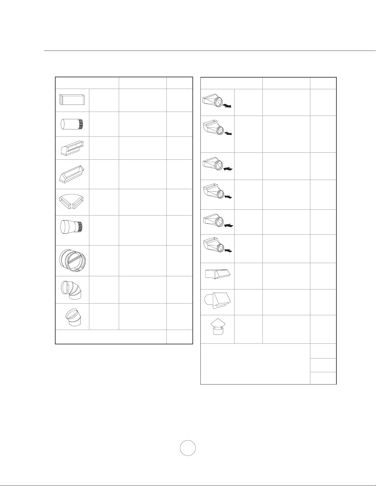
Duct pieces
3- 1/4” x 10”
Rect.,
straight
6”, 7”, 8”, 10”
Round,
straight
3- 1/4” x 10”
Rect. 90
elbow
3- 1/4” x 10”
Rect. 45
elbow
3- 1/4” x 10”
Rect. 90
flat elbow
7” to 6” or
8” to 7” Round
tapered
reducer
6”, 7“, 8”
Round
in-line
damper
6”, 7”, 8”, 10”
Round,
0
90
elbow
Installation – Ductwork Calculation Sheet
6”, 7”, 8”, 10”
Round,
0
45
elbow
Equivalent number
length x used =
1 Ft. x ( ) =
1 Ft. x ( ) =
15 Ft. x ( ) =
0
9 Ft. x ( ) =
0
24 Ft. x ( ) =
0
25 Ft. x ( ) =
15
Ft. x ( ) =
15 Ft.
9 Ft. x ( ) =
Subtotal column 1 =
x ( ) =
To tal
Ft.
Ft.
Ft.
Ft.
Ft.
Ft.
Ft.
Ft.
Ft.
Ft.
Duct pieces
3- 1/4” x 10”
Rect. to
6” round
transition
3- 1/4” x 10”
Rect. to
6” round
transition
0
elbow
90
6” round to
3- 1/4” x 10”
rect.
transition
6” round to
3- 1/4” x 10”
rect.
transition
0
90
elbow
7” round to
3 1/ 4” x 10”
rect.
transition
7” round to
3- 1/4” x 10”
rect.
transition
0
elbow
90
3- 1/4” x 10”
Rect.
wall cap
with damper
6”, 7”, 8”, 10”
Round, wall
cap with
damper
6”, 7”, 8”, 10”
Round
roof cap
Equivalent number
length x used =
5 Ft. x ( ) =
20 Ft. x ( ) =
1 Ft. x ( ) =
16 Ft. x ( ) =
8 Ft. x ( ) =
23 Ft. x ( ) =
30 Ft. x ( ) =
30 Ft. x ( ) =
30 Ft. x ( ) =
To tal
Ft.
Ft.
Ft.
Ft.
Ft.
Ft.
Ft.
Ft.
Ft.
Maximum Duct Length: For satisfactory air movement,
the total duct length
should not exceed 100 equivalent feet.
Subtotal column 2 =
Subtotal column 1 =
Total ductwork =
Ft.
Ft.
Ft.
4
Page 7

outlet
4
5
2
outlet
outlet
outlet
1
Plywood
3
WARNING:
Check installation position so that the blower outlet is exhausting air away from the hood and
out of the home.
1. Mount on top of ceiling joists with plywood
2. Vertical mount to cross-members tied to trusses
3. Horizontal mount to cross-members tied to trusses
4. Mount on underside of rafters with wood blocking
5. Mount to cross-members tied to trusses with 90 degree elbow
Note1: When applicable, additional plywood may be used to simplify installation.
Note2: For some models it is necessary to convert from 10” round to 8” round ducting. A
10” to 8” transition is included with the blower. Conversion must be done before ducting
passes through ceiling.
Installation – Blower Positions
5
Page 8

www.zephyronline.com
1
1 9/16”
1 11/16”
Installation – Specications
front side
outlet outlet
15 7/8”
20 15/16”
20 3/8”
top
(outlet)
9 15/16”
7 5/16”
6 13/16”
3
7 5/16”
(bracket positions)
bottom
(inlet)
10 1/16”
bracket
5 1/2”
14 3/16”
10 3/8”
14 5/8”
21 7/8”
23 7/16”
8 5/8”
11 13/16”
6
Page 9

1. Determine blower position (examples on page 5).
bracket positions
outlet
d
due
!
accordance
properly grounded. Turn off electrical power at service entrance before wiring.
White (common)
Black (high)
Blue (med)
Red (low)
Green (ground)
PBN-1000A
HOOD
wiring harness
outlet
10” round
ducting
10” round
ducting
10” to 8”
transition
(if needed)
ceiling
wood
stud
PBN-1000A
in-line blower
bracket
electrical
conduit
8” round
ducting
Cable
Lock
Install each of the (2) mounting brackets to the sides of
the in-line blower housing using (4) M4x8 screws per
bracket. There are possible (4) mounting positions for
the brackets. FIG. A Note: Brackets must be secured
to studs using (2) M4 x 1-1/2” screws per bracket.
2. Run 10” round ducting to inlet and outlet of in-line blower
housing. Secure with aluminum duct tape. Note: Cheng
and Arc Collection hoods require a 10” to 8” round
transition to be installed prior to the duct passing through
the ceiling. 8” round ducting is then connected to the hood.
A 10” to 8” transition is included with the blower. FIG. B
3. Run electrical conduit per local codes from junction
box on top of in-line blower to blower wiring
harness on top of the range hood. See instructions
included with range hood for more information.
4. Run (5) wires through conduit (black, white, blue, red
and green ground). Check local code compliance
for style and gauge of wires. The ground wire shall
have a suitable gauge according to the Electrical Code
and Regulations. Connect wires to in-line blower and
blower wiring harness on hood per the diagram in FIG.
C. A cable lock (not supplied) might be required by local
codes. Check with local code requirements, purchase
and install appropriate connector if necessary. FIG. D
5. Turn circuit breaker on, power on hood and test all
functions. Check for leaks around duct connections.
FIG. A
Installation – Mounting the Blower
CAUTION: At least two installers are require
to the weight and size of the blower.
WARNING: Electrical wiring must be done by a qualified person(s) in
!
with all applicable codes and standards. This range hood must be
FIG. C FIG. D
7
FIG. B
 Loading...