

Page 1
www.zephyronline.com
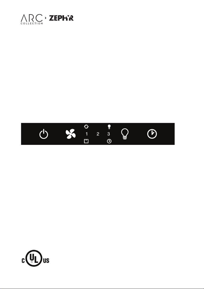
USER GUIDE - TOUCH GLASS CONTROLS
Page 2

www.zephyronline.com
Page 3

CONTROLS - User instructions Pag. 4
COMMANDES - Notice d’utilisation Pag. 16
MANDOS - Manual de utilización Pag. 28
COMANDI - Istruzioni per l’uso Pag. 40
Page 4

USA
1. SAFETY
1.1 Safety...............................................................................................................................................5
2. REMOTE CONTROL
2.1 Synchronisation.............................................................................................................................7
2.2 Operation.......................................................................................................................................7
2.3 General Information....................................................................................................................7
Contents
3. USER INTERFACE
3.1 Keypad layout................................................................................................................................8
3.2 Display layout.................................................................................................................................8
4. INDIVIDUAL BUTTON FUNCTIONS
4.1 Power Button (1).............................................................................................................................9
4.2 Fan Speed Button (2).....................................................................................................................9
4.3 Light Button (3)...............................................................................................................................9
4.4 Delay O ff Button (4)........................................................................................................................9
5. DISPLAY OPTIONS
5.1 Light I ndicator..............................................................................................................................10
5.2 Filter Clean and Charcoal Filter Replace Indicators.......................................................10
- Metal Filter Clean Indicator
- Charcoal Filter Replace Indicator
5.3 Delay Off Indicator.....................................................................................................................11
5.4 Clean Air Indicator......................................................................................................................11
5.5 Fan Speed Indicator...................................................................................................................12
www.zephyronline.com
6. MAINTENANCE
6.1 Maintenance...............................................................................................................................13
6.2 Replacing the light bulb........................................................................................................14
- 4 -
Page 5

IMPORTANT SAFETY INSTRUCTIONS
FOR RESIDENTIAL USE ONLY
READ AND SAVE THESE INSTRUCTIONS
PLEASE READ ENTIRE INSTRUCTIONS BEFORE PROCEEDING.
IMPORTANT: Save these Instructions for the Local Electrical Inspectors use.
INSTALLER: Please leave these Instructions with this unit for the owner.
OWNER: Please retain these instructions for future reference.
Take care when using cleaning agents or detergents.
Suitable for use in household cooking area
WARNING - To reduce the risk of re or electric shock, do not use this fan with any Solid-State
Speed Control Device.
CAUTION - To reduce risk of re and to properly exhaust air, be sure to duct air outside – Do
not vent exhaust air into spaces within walls or ceilings or into attics, crawl spaces, or garages.
CAUTION - For general ventilating use only. Do not use to exhaust hazardous or explosive
materials and vapors.
CAUTION - To avoid motor bearing damage and noisy and/or unbalanced impellers, keep drywall
spray, construction dust, etc. o power unit.
CAUTION - Please read speci cation label on product for further information and require-
ments.
WARNING – TO REDUCE THE RISK OF FIRE, ELECTRIC SHOCK, OR INJURY TO PERSONS, OBSERVE
THE FOLLOWING:
A. Use this unit only in the manner intended by the manufacturer. If you have ques tions,
contact the manufacturer.
B. Before servicing or cleaning unit, switch power o at service panel and lock the service
disconnecting means to prevent power from being switched on accidentally. When the service
disconnecting means cannot be locked, securely fasten a prominent warning device, such as a
tag, to the service panel.
1. Safety
WARNING - TO REDUCE THE RISK OF A RANGE TOP GREASE FIRE:
A. Never leave surface units unattended at high settings. Boilovers cause smoking and greasy
spillovers that may ignite. Heat oils slowly on low or medium settings.
B. Always turn hood ON when cooking at high heat or when ambeing foods ( i.e. Crepes Suzette,
Cherries Jubilee, Peppercorn Beef Flambè ).
C. Clean ventilating fans frequently. Grease should not be allowed to accumulate on fan or
lter.
D. Use proper pan size. Always use cookware appropriate for the size of the surface element.
E. Keep fan, lters and grease laden surface clean.
F. Use high range setting on range only when necessary.Heat oil slowly on low to medium set-
ting.
- 5 -
Page 6

www.zephyronline.com
G. Don’ t leave range unattended when cooking.
H. Always use cookware and utensils appropriate for the type and amount o food being pre-
pared.
WARNING – TO REDUCE THE RISK OF INJURY TO PERSONS IN THE EVENT OF A RANGE TOP
GREASE FIRE, OBSERVE THE FOLLOWING:
A. SMOTHER FLAMES with a close- tting lid, cookie sheet, or metal tray, then turn o the burner.
1. Safety
BE CAREFUL TO PREVENT BURNS. If the ames do not go out mmediately, EVACUATE AND CALL
THE FIRE DEPARTMENT.
B. NEVER PICK UP A FLAMING PAN – You may be burned.
C. DO NOT USE WATER, including wet dishcloths or towels – a violent steam explosion will re-
sult.
D. Use an extinguisher ONLY if:
1. You know you have a Class ABC extinguisher, and you already know how to perate it.
2. The re is small and contained in the area where it started.
3. The re department is being called.
4. You can ght the re with your back to an exit.
Proper maintenance of the Range Hood will assure proper performance of the unit.
INSTALLATION INSTRUCTIONS
WARNING – TO REDUCE THE RISK OF FIRE, ELECTRIC SHOCK, OR INJURY TO PERSONS, OBSERVE
THE FOLLOWING:
A. Installation work and electrical wiring must be done by quali ed person(s) in accordance with
all applicable codes and standards, including re-rated construction.
B. Su cient air is needed for proper combustion and exhausting of gases through the ue (chimney)
of fuel burning equipment to prevent back drafting. Follow the heating equipment manufacturer’s
guideline and safety standards such as those published by the National Fire Protection Association (NFPA), and the American Society for Heating, Refrigeration and Air Conditioning Engineers
(ASHRAE), and the local code authorities.
C. When cutting or drilling into wall or ceiling, do not damage electrical wiring and other hidden
utilities.
D. Ducted fans must always be vented to the outdoors.
E. This unit must be grounded.
WARNING - TO REDUCE THE RISK OF FIRE, USE ONLY METAL DUCTWORK.
WARNING - UNDER CERTAIN CIRCUMSTANCES DOMESTIC APPLIANCES MAY BE DANGEROUS.
A. Do not check lters with hood working.
B. Do not touch the lamps after a prolonged use of the appliance.
C. No food must be cooked ambè underneath the hood.
D. The use of an unprotected ame is dangerous for the lters and could cause res.
E. Watch constantly the fried food in order to avoid the cooking oil ares up.
F. before performing any mainteinance operation, disconnect the hood from the electrical ser-
vice.
The manufacturers will not to accept any responsability for eventual damages, because of failure
to observe the above instructions.
- 6 -
Page 7
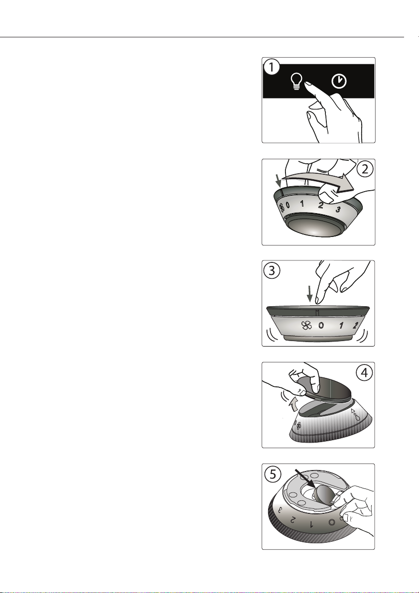
2.1 SYNCHRONISATION:
To synchronise the remote control with the range hood for
the rst time, proceed as follows:
1. With range hood o , press and hold the “lights” button on
the range hood until the light indicator begins to ash.
Fig.1
2. Rotate the upper part of the remote control until the “lights”
indicator light on the range hood switches o . Fig. 2
The range hood may now be activated using the remote
control. If you experience any problems, repeat the
procedure.
2.2 OPERATION:
- BLOWER SPEED:
The blower speed may be adjusted by rotating the upper
part of the remote control and aligning the marker with the
desired speed. Fig. 2
0= O
1= Low
2= Medium
3= High
- LIGHTS:
The lights may be switched on by pressing the remote
control. Fig. 3
The brightness may be progressively reduced by pressing it
a second or third time.
The fourth time the remote control is pressed, the lights will
be switched o .
2.3 GENERAL INFORMATION:
- The remote control has a range of approximately 15-20
feet.
- The remote control is equipped with a magnetic base and
may therefore be attached to ferrous surfaces.
- BATTERY REPLACEMENT:
The battery will last for approximately 12-15 months,
depending on usage.
2. Remote Control
1. Remove the rubber cover as shown in Fig. 4
2. Remove the battery by pressing the side of it. Fig. 5
3. Replace the battery with a 3 volt type 5004LC / CR 2032
- 7 -
Page 8
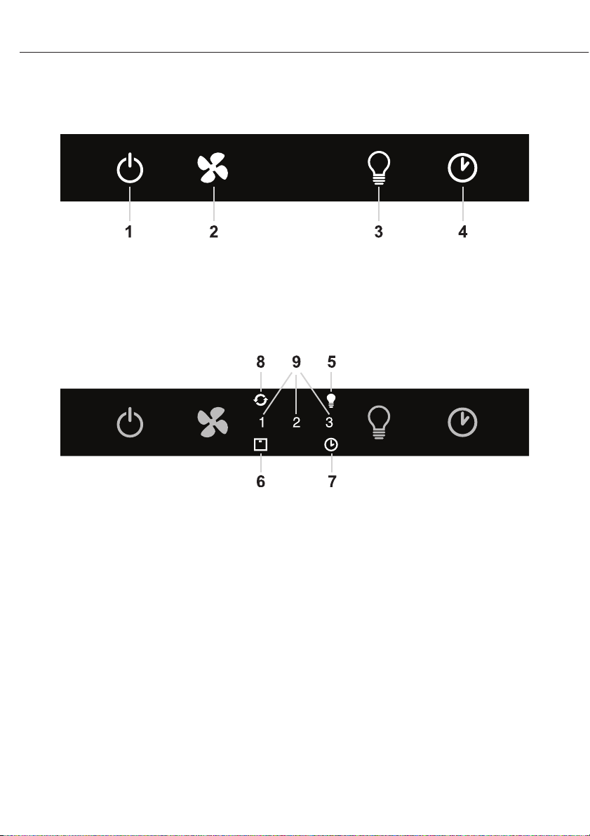
3.1 KEYPAD LAYOUT
3. User Interface
3.2 DISPLAY LAYOUT
www.zephyronline.com
- 8 -
Page 9

4.1 POWER BUTTON (1)
- Power Button will turn power on and off for the entire hood (fan and lights)
- Hood will remember the last speed and light level it was last turned off at (Example: hood is turned off at when it was last on high speed and high lights; hood will turn back on at high speed
and high lights when Power Button is pressed)
4.2 FAN SPEED BUTTON (2)
- From off, press once for low speed (1), twice for medium (2), and three times for high (3).
- Fan should cycle through speeds low (1), medium (2), and high (3) continuously.
4.3 LIGHT BUTTON (3)
- Lights are three level (high, medium, low)
- From off, touch once for high
- From off, touch twice for medium
- From off, touch three times for low
- From off, touch four times to cycle back to off
- Light level will cycle from high, medium, low, off
4.4 DELAY OFF BUTTON (4)
4. Individual Button Functions
- If fan is off, press once and fan will turn on at low speed and automatically turn off after five (5)
minutes.
- If the fan is already on (example high speed) the fan will change to low speed when the Delay
Off Button is pressed and turn off after five minutes.
- When the Delay Off Function is on, the user can still change the fan speed by pressing the Fan
Speed Button without interrupting the five minute Delay Off Timer.
- Delay Off Function can be turned off by pressing Delay Off Function button or Power Button.
- 9 -
Page 10
www.zephyronline.com
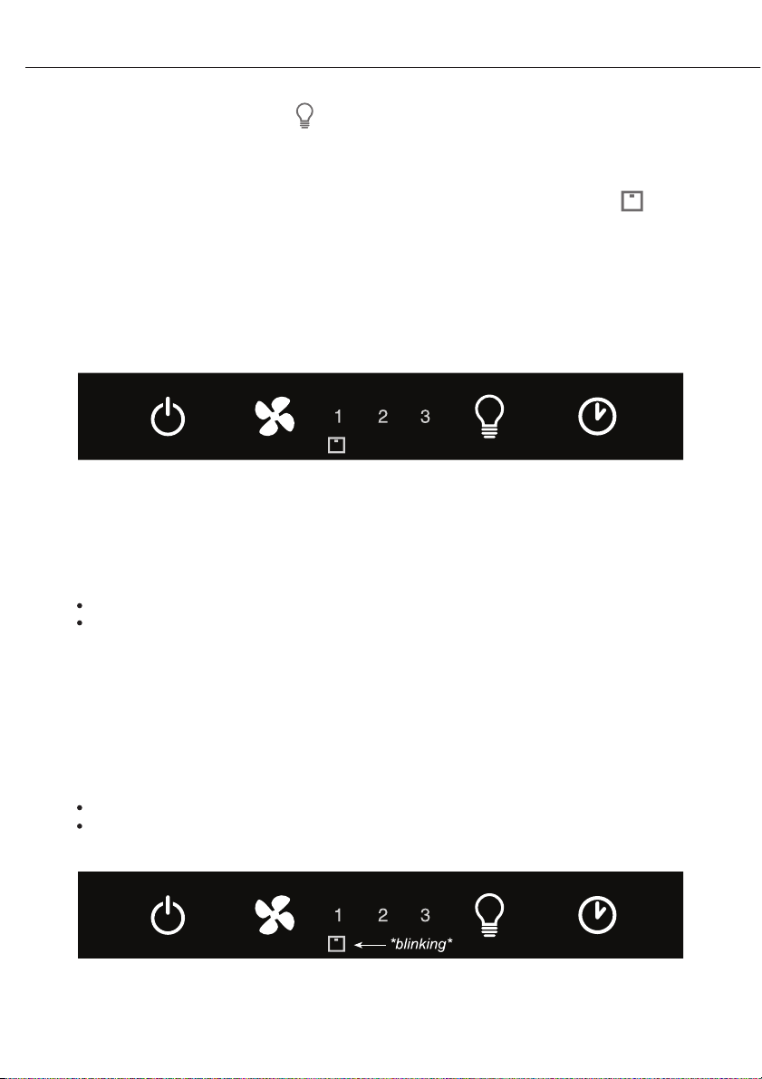
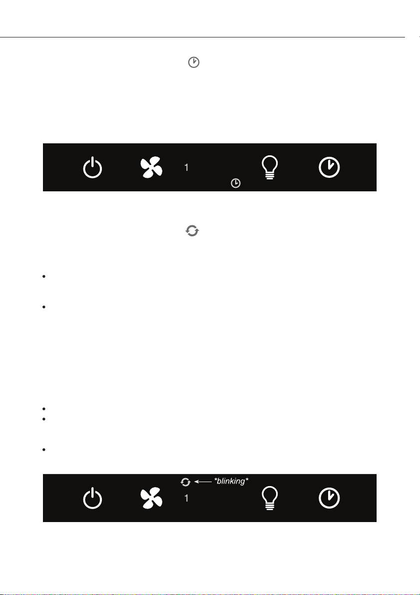
5.1 LIGHT INDICATOR (5)
- Light indicator will turn on when lights are turned on at any light level
5.2 FILTER CLEAN AND CHARCOAL FILTER REPLACE INDICATOR (6)
ETAL FILTER CLEAN (always enabled)
- M
- Filter Clean Indicator will illuminate after 30 hours of fan usage indicating it is time to clean the
metal filter. Indicator light will remain illuminated, it will not blink
- This function must be reset by the user. With hood off, hold the Fan Speed Button for five seconds, after five seconds the Filer Clean Indicator will turn off and the 30 hour timer will reset
5. Display Options
clean metal filter indicator becomes illuminated and fan on speed 3 (indicator turns on after 30 hours of fan usage)
- CHARCOAL FILTER REPLACE (disabled by default, must be enabled by user if recirculating
hood)
- To enable Charcoal Filter Replacement Function:
With hood off, hold Fan Speed and Delay Off buttons simultaneously for 5 seconds.
Filter Clean Indicator will quickly flash 3 times indicating the Charcoal Filter Replacement Fun-
ction is enabled.
- Filter Clean Indicator will continuously blink after 120 hours of unit fan usage indicating it is time
to replace the charcoal filter. Indicator light will blink, it will not remain illuminated.
- This function must be reset by the user. With hood off, hold the Delay Off Button for five seconds,
after five seconds the Filter Clean Indicator will stop blinking and turn off and the 120 hour timer
will reset.
Order replacement charcoal filter kit number Z0F-00AC through your local dealer,
www.zephyronline.com or the Zephyr customer service department.
- To disable Charcoal Filter Replacement Function:
With hood off, hold Fan Speed and Delay Off buttons simultaneously for 5 seconds.
Filter Clean Indicator will illuminate for 3 second then turn off indicating the Charcoal Filter Re-
placement Function is disabled.
replace charcoal filter indicator blinking and fan on speed 3 (indicator turns on after 120 hours of fan usage)
- 10 -
Page 11
5.3 DELAY OFF INDICATOR (7)
- Delay Off Indicator will light up when Delay Off Function is activated by pressing the Delay Off
Button.
- Delay Off Indicator will turn off after the Delay Off Function has completed the five minute
cycle or if the user presses the Delay Off Button again or the Power Button.
delay off timer enabled and fan speed changed to 1
5.4 CLEAN AIR INDICATOR (8)
- Clean Air Indicator is disabled by default and must be enabled by the user.
- To enable Clean Air Function:
With hood off, hold the Power Button down for five seconds. Clean Air Indicator light will illuminate, and the fan will turn on low speed for 10 minutes. After 10 minutes the fan will turn off and
the 4 hour timer will begin.
Clean Air Indicator will remain on when Clean Air Function is enabled, even if fan is not on.
- When Clean Air Function is enabled, every four hours of non fan usage the fan will automatically
turn on at low speed for 10 minutes. After 10 minutes the fan will turn off and the 4 hour timer
will reset.
- When the Clean Air Function automatically turns the fan on the Clean Air Indicator will blink and
the Low Speed fan indicator will illuminate.
- If the user changes the fan speed while the Clean Air Function is operating, the Clean Air Indicator
will stop blinking but will remain illuminated. When the user manually turns the hood off the 4
hour timer will reset.
- To disable Clean Air Function:
With hood off, hold Power Button down for five seconds until Clean Air Indicator light turns off.
Note1: Changing the fan speed and interrupting the Clean Air Function while it is operating does
not disable the Clean Air Function. Clean Air Function will only be disabled by holding the Power
Button for 5 seconds
Note2: Turning lights on/off does not disable the Clean Air Function
5. Display Options
clean air function enabled with low fan speed turned on by clean air function
- 11 -
Page 12

5.5 FAN SPEED INDICATOR (9)
1 = Low
2 = Medium
3 = High
- On speed low, only number 1 indicator will be on
- On speed medium, 1 and 2 indicator will be on
- On speed high, 1, 2 and 3 indicators will be on
- When fan off, no fan speed indicator will be on
5. Display Options
www.zephyronline.com
- 12 -
Page 13

6.1 MAINTENANCE
• It is recommended to operate the range hood prior to cooking. It is recommended to leave
the range hood in operation for 15 minutes after cooking is terminated in order to completely
eliminate cooking vapors and odors. The proper function of the range hood is conditioned
by the regularity of the maintenance operations.
• The anti-grease lters capture the grease particles suspended in the air, and are therefore
subject to clogging according to the frequent use of the range hood. In order to prevent re
hazard, it is recommendable to clean the lter a minimum of every 2 months by carrying out
the following instructions:
- Remove the lters from the range hood and wash them in a solution of water and neutral
liquid detergent, leaving to soak.
- Rinse thoroughly with warm water and leave to dry.
- The lters may also be washed in the dishwasher at low setting.
The aluminium panels may discolor after several washes. This is not cause for customer
complaint nor replacement of panels.
• Clean the fan and other surfaces of the cooker hood regularly using a cloth moistened with
denatured alcohol or non abrasive liquid detergent.
6. Maintenance
- 13 -
Page 14
www.zephyronline.com
6.2 REPLACING THE LIGHT BULB:
WARNING
Disconnect the hood from electricity and be sure the lights are cool.
If new lights do not operate, make sure the light bulb is inserted correctly before calling service.
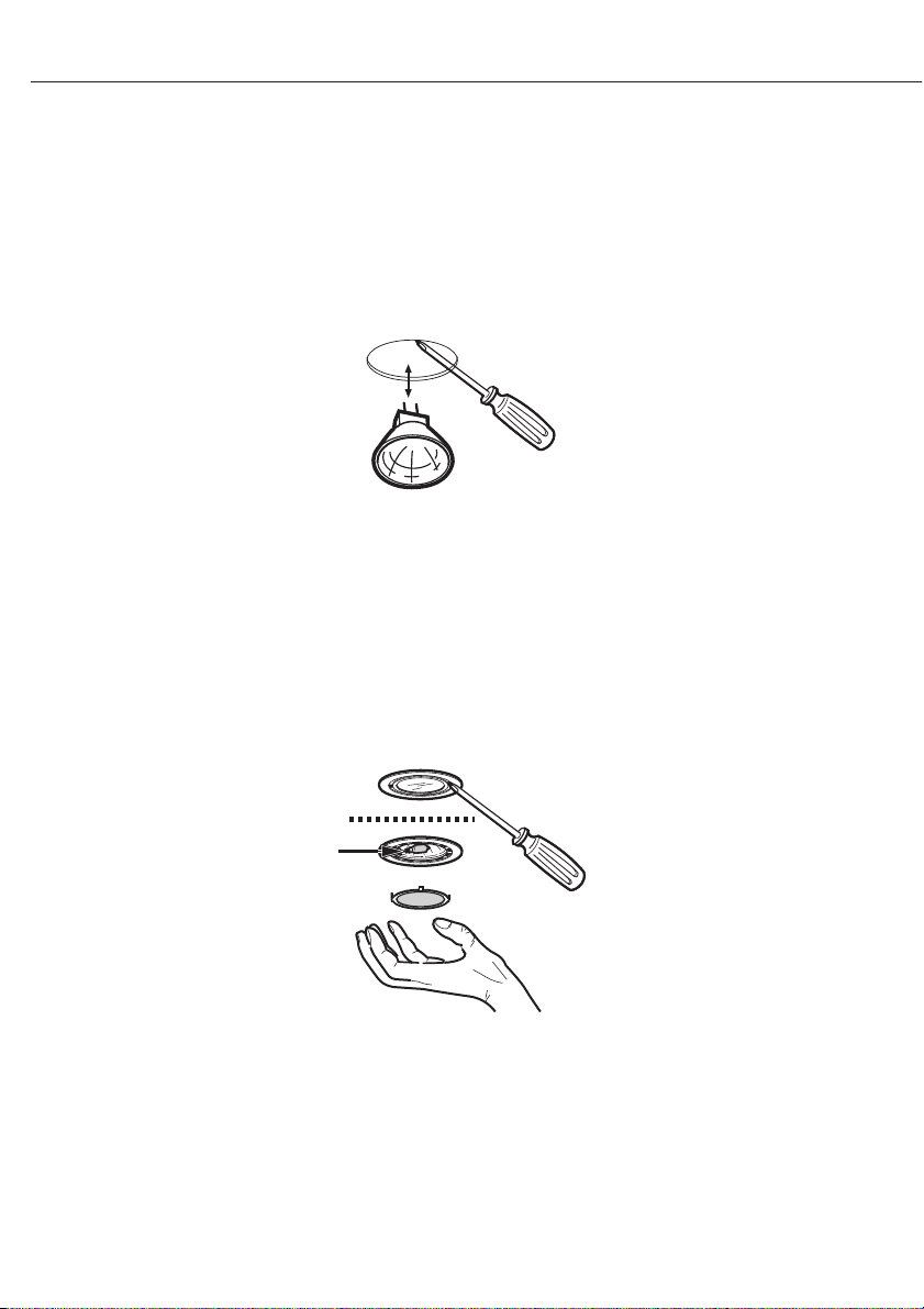
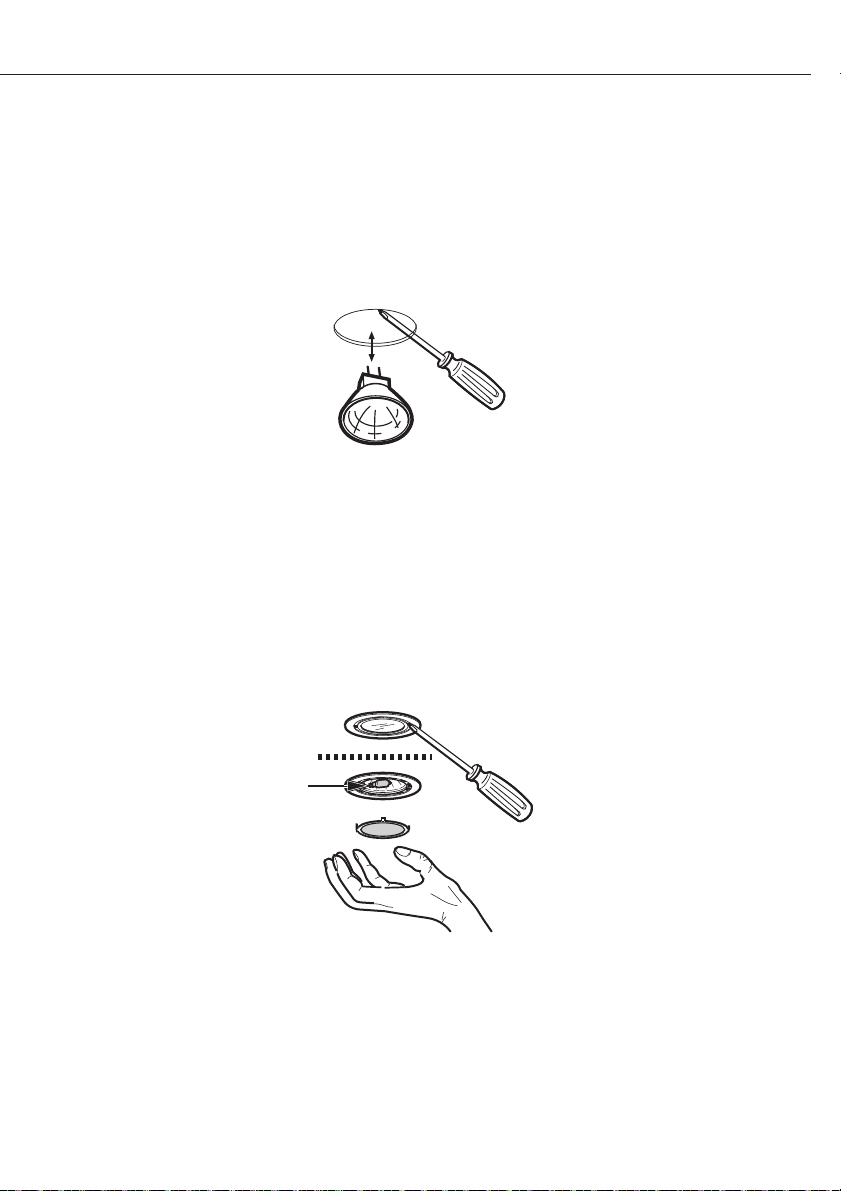
For bulb type GU4/MR11 12V 20W; hood models ALA, ALL, APN, ASU and ASL
For bulb type GU5/MR16 12V 20W; hood models AHZ and ATI
6. Maintenance
- Using a small at head screwdriver or equivalent tool, carefully pry loose the light bulb to disconnect it from the spring clamps in the socket. Take care not to scratch the bottom of the hood.
- Pull down on bulb to remove.
- Check proper orientation of bulb to socket before inserting new bulb. Push upwards until bulb
engages into socket and spring clamps. Replacement bulb must have a safety heat fused lens “suitable for use in open luminaries”.
For bulb type G4 12V 20W; hood models ADU, ADL, and AED
light bulb
- Using a small at head screwdriver or equivalent tool, carefully pry loose the light cover. Take care
not to scratch the bottom of the hood.
- Remove the defective light bulb and replace with a new light bulb, “suitable for use in open luminaries”. Follow package directions and do not touch new light bulb with bare hands.
- Reinstall the light cover.
- 14 -
Page 15

STAPLE YOUR RECEIPT HERE
Proof of the original purchase
date is needed to obtain
service under warranty
TO OBTAIN SERVICE UNDER WARRANTY OR FOR ANY SERVICE RELATED QUESTIONS, please call:
1-888-880-8368
Zephyr Corporation (referred to herein as “we” or “us” ) warrants to the original consumer purchaser (referred to herein
as “you” or “your” ) of Zephyr products ( the “Products” ) that such Products will be free from defects in materials or
work-manship as follows:
One Year Limited Warranty for Parts: For one year from the date of your original purchase of the Products, we will
provide, free of charge, Products or parts to replace those that failed due to manufacturing defects. We may choose, in
our sole discretion, to repair or replace parts before we elect to replace the Products.
One Year Limited Warranty for Labor: For one year from the date of your original purchase of the Products, we will
provide,free of charge, the labor cost associated with repairing the Products or part store place those that failed due to
manufacturing defects. After the rst year from the date of your original purchase, you are responsible for all labor costs
associated with this warranty.
Warranty Exclusions: This warranty covers only repair or replacement, at our option, of defective Products or parts and
does not cover any other costs related to the Products including but not limited to: (a) normal maintenance and service
required for the Products and consumable parts such as light bulbs, metal and carbon lters and fuses; (b) any Products or
parts which have been subject to freight damage, misuse, negligence, accident, faulty installation or installation contrary
to recommended installation instructions, improper maintenance or repair ( other than by us ) ; (c) commercial use of the
Products or use otherwise inconsistent with its intended purpose; (d) natural wear of the nish of the Products or wear
caused by improper maintenance, use of corrosive and abrasive cleaning products, pads, and oven cleaner products; (e)
chips, dents or cracks caused by abuse or misuse of the Products; (f) service trips to your home to teach you how to use
the Products; or (g) damage to the Products caused by accident, re, oods or act of God. If you are outside our service
area, additional charges may apply for shipping costs for warranty repair at our designated service locations and for the
travel cost to have a service technician come to your home to repair, remove or reinstall the Products. After the rst year
from the date of your original purchase, you are also responsible for all labor costs associated with this warranty.
Limitations of Warranty. OUR OBLIGATION TO REPAIR OR REPLACE, AT OUR OPTION, SHALL BE YOUR SOLE AND
EXCLUSIVE REMEDY UNDER THIS WARRANTY. WE SHALL NOT BE LIABLE FOR INCIDENTAL, CONSEQUENTIAL OR
SPECIAL DAMAGES ARISING OUT OF OR IN CONNECTION WITH THE USE OR PERFORMANCE OF THE PRODUCTS. THE
EXPRESS WARRANTIES IN THE PRECEDING SECTION ARE EXCLUSIVE AND IN LIEU OF ALL OTHER EXPRESS WARRANTIES. WE HEREBY DISCLAIM AND EXCLUDE ALL OTHER EXPRESS WARRANTIES FOR THE PRODUCTS, AND DISCLAIM
AND EXCLUDE ALL WARRANTIES IMPLIED BY LAW, INCLUDING THOSE OF MERCHANTABILITY AND FITNESS FOR A
PARTICULAR PURPOSE. Some states or provinces do not allow limitations on the duration of an implied warranty or the
exclusion or limitation of incidental or consequential dam-ges, so the above limitations or exclusions may not apply to
you. To the extent that applicable law prohibits the exclusion of implied warranties, the duration of any applicable implied
warranty is limited to the same one-year period described above. Any oral or written description ofthe Products is for the
sole purpose of identifying the Products and shall not be construed as an express warranty. Prior to using, implementing
or permitting use of the Products, you shall determine the suitability of the Products for the intended use, and you shall
assume all risk and liability whatsoever inconnection with such determination. We reserve the right to use functionally
equivalent refurbished or reconditioned parts or Products as warranty replacements or as part of warranty service. This
warranty is not transferable from the original purchaser and applies in the United States and Canada.
To Obtain Service Under Limited Warranty: To qualify for warranty service, you must: (a) notify us at the address or
telephone number stated below with in 60 days of the discovery of the defect; (b) give the model number and part
identi cation number and serial number; and (c) describe the nature of any defect in the Product or part. At the time of
the request for warranty service, you must present evidence of your proof of purchase and proof of the original purchase
date. If we determine that the warranty exclusions list ed above apply or if you fail to provide the necessary documentation
to obtain service, you will be responsible for all shipping, travel, labor and other costs related to the services.
Please check our website for any revisions, www.zephyronline.com
Zephyr Corporation Service Department, 2277 Harbor Bay Parkway, Alameda, CA94502 1-888-880-8368
JUN08.0101
- 15 -
Page 16

F
1. SÉCURITÉ
1.1 Sécurité........................................................................................................................................17
2. TÉLÉCOMMANDE
2.1 Synchronisation.......................................................................................................................20
2.2 Fonctionnement.......................................................................................................................20
2.2 Informations générales.........................................................................................................20
www.zephyronline.com
Sommaire
3. INTERFACE UTILISATEUR
3.1 Configuration Des Commandes..........................................................................................21
3.2 Configuration De L’écran......................................................................................................21
4. FONCTIONS DES TOUCHES
4.1 Allumage/Extinction (1)........................................................................................................22
4.2 Vitesse Turbine (2)....................................................................................................................22
4.3 Lumières (3)...............................................................................................................................22
4.4 Extinction Différée (4)............................................................................................................22
5. AFFICHAGE SUR L’ECRAN
5.1 Voyant Lumières.........................................................................................................................23
5.2 Voyant nettoyage filtre voyant remplacement du filtre à charbo..........................23
- Voyant nettoyage du filtre métallique
- Voyant de remplacement du filtre à charbon
5.3 Voyant d’extinction différée...................................................................................................24
5.4 Voyant d’air propre....................................................................................................................24
5.5 Voyant vitesse turbine.............................................................................................................25
6. MANTENANCE
6.1 Mantenance.................................................................................................................................26
6.2 Remplacement De L’ampoule..............................................................................................27
- 16 -
Page 17

INSTRUCTIONS DE SECURITE IMPORTANTES
POUR UN USAGE DOMESTIQUE EXCLUSIVEMENT
LIRE ET CONSERVER LES INSTRUCTIONS
COMMENCER PAR LIRE ENTIEREMENT LES INSTRUCTIONS.
IMPORTANT: Conserver les Instructions à usage des Inspecteurs Electriques Locaux.
A L’ATTENTION DE L’INSTALLATEUR : Laisser les Instructions dans l’unité à usage du
propriétaire.
A L’ATTENTION DU PROPRIETAIRE : Conserver les Instructions pour des consultations
ultérieures.
N’utiliser des produits de nettoyage ou des détergents qu’avec la plus grande prudence.
Cet appareil est propre à une utilisation domestique et culinaire.
AVERTISSEMENT – A n de réduire les risques d’incendie ou d’électrocution, ne pas utiliser
le moteur avec un Dispositif de Contrôle de la Vitesse à Semi-conducteurs quel qu’il soit.
ATTENTION – A n de réduire les risques d’incendie et de permettre une aspiration correcte
de l’air, s’assurer que celui-ci est bien transporté à l’extérieur à travers un conduit d’évacuation.
– Ne pas évacuer l’air dans des interstices tels qu’entre des cloisons ou des plafonds, dans des
greniers, des espaces con nés ou des garages.
ATTENTION – N’utiliser que pour une ventilation générique. Cet appareil n’est pas propre
à l’aspiration de matières ou de vapeurs dangereuses ou explosives.
ATTENTION – A n d’éviter des bruits et des dommages au niveau du moteur, et/ou un
déséquilibre au niveau des hélices, veiller à ce que l’unité d’alimentation n’entre pas en contact
avec du spray, de la poussière etc.
1. Sécurité
ATTENTION – Pour obtenir des compléments d’informations, consulter l’étiquette de spé-
ci cation sur le produit.
AVERTISSEMENT – AFIN DE RÉDUIRE LES RISQUES D’INCENDIE, D’ÉLECTROCUTION OU DE
DOMMAGES AUX PERSONNES, RESPECTER LES REGLES SUIVANTES :
A. N’utiliser l’unité que pour les opérations prévues par le fabricant. Pour toute question
éventuelle, contacter le fabricant.
B. Avant d’e ectuer des opérations de maintenance ou de nettoyage sur l’unité, débrancher
le panneau de service et fermer à clef les commandes de déconnection a n d’éviter toute
mise sous tension accidentelle.
Au cas où les commandes de déconnection ne pourraient être fermées à clef, xer sur le
panneau de service un message avertissant du danger, par exemple une plaque.
AVERTISSEMENT – AFIN DE RÉDUIRE LES RISQUES D’INCENDIE PAR INFLAMMATION DES
GRAISSES PRESENTES SUR LA GAZINIERE :
A. Ne jamais laisser de casseroles sur feu vif sans surveillance. D’éventuels débordements dus
à une forte ébullition peuvent provoquer de la fumée et des dépôts de graisses susceptibles
de prendre feu. Réchau er l’huile lentement, à petit feu ou moyen.
- 17 -
Page 18

www.zephyronline.com
B. ALLUMER systématiquement la hotte pour cuisiner à des températures élevées ou pour
amber des aliments (ex. : Crêpes Suzette, Cherries Jubilee – cerises ambées au brandy et
glace -, Boeuf ambé au poivre).
C. Nettoyer souvent le moteur. Eviter que les graisses ne s’accumulent sur le moteur ou sur
le ltre.
D. Utiliser des plats aux dimensions adaptées. Toujours utiliser des ustensiles de cuisine adaptés
à la taille de la casserole qui se trouve sur la cuisinière.
E. Veiller à ce que le moteur, les ltres et la surface où viennent s’accumuler les graisses
1. Sécurité
restent propres.
F. N’utiliser une amme élevée que lorsque cela est nécessaire. Réchau er l’huile lentement,
à faible ou moyenne température.
F. Ne jamais laisser la cuisinière sans surveillance pendant la cuisson.
G. Utiliser systématiquement des ustensiles de cuisine adaptés au type et à la quantité d’ali-
ments que l’on prépare.
AVERTISSEMENT – AFIN DE RÉDUIRE LES RISQUES DE DOMMAGES AUX PERSONNES EN CAS
D’INCENDIE PAR INFLAMMATION DES GRAISSES PRESENTES SUR LA CUISINIERE, RESPECTER
LES REGLES SUIVANTES:
A. ETOUFFER LA FLAMME à l’aide d’un couvercle hermétique, une plaque à four ou un plateau
en métal et éteindre le brûleur. PROCEDER AVEC LA PLUS GRANDE PRUDENCE AFIN D’EVITER
TOUTE BRULURE. Si les ammes ne s’éteignent pas immédiatement, EVACUER LA PIECE ET
APPELER LES POMPIERS.
B. NE JAMAIS TOUCHER UN PLAT EN FEU – on risque de se brûler.
C. NE PAS UTILISER D’EAU, ni de chi ons ou de serviettes humides – cela pourrait provoquer
une violente explosion de vapeur.
D. Utiliser un extincteur UNIQUEMENT dans les cas suivants :
1. On dispose d’un extincteur de Classe ABC que l’on sait faire fonctionner.
2. L’incendie est peu important et il est con né à la zone où il a éclaté.
3. On a déjà appelé les pompiers.
4. On peut a ronter les ammes tout en ayant une issue de secours derrière soi.
Une bonne maintenance de la hotte garantit le parfait fonctionnement de l’unité.
INSTRUCTIONS D’INSTALLATION
AVERTISSEMENT – AFIN DE RÉDUIRE LES RISQUES D’INCENDIE, D’ÉLECTROCUTION OU DE
DOMMAGES AUX PERSONNES, RESPECTER LES REGLES SUIVANTES :
A. Les opérations d’installation et de branchement électrique doivent être e ectuées par du
personnel quali é, conformément aux lois et aux normes en vigueur, y compris celles relatives
aux appareils à feu.
B. Il est nécessaire de disposer d’une quantité d’air su sante pour une bonne combustion et
aspiration des gaz à travers le conduit de fumée de l’installation de combustion du carburant,
a n d’éviter un appel d’air de l’arrière. Suivre les indications du fabricant de l’installation de
chau age et les normes de sécurité correspondantes telles que celles émises par l’Association
Nationale de Protection contre les Incendies (National Fire Protection Association - NFPA),
la Société Américaine des Techniciens de Chau age, Réfrigération et Climatisation de l’Air
(American Society for Heating, Refrigeration and Air Conditioning Engineers - ASHRAE), et
par les autorités locales préposées.
C. Au cours des opérations de découpage ou de perforation du mur ou du plafond, veiller à
ne pas endommager les câbles électriques ou d’autres canalisations cachées.
- 18 -
Page 19

D. L’appareil doit toujours être relié à un trou d’évacuation vers l’extérieur.
E. L’unité doit être reliée à la terre.
AVERTISSEMENT – AFIN DE RÉDUIRE LES RISQUES D’INCENDIE, N’UTILISER QUE DES CON-
DUITS METALLIQUES
AVERTISSEMENT – LES APPAREILS ELECTROMENAGERS PEUVENT PARFOIS S’AVERER DAN-
GEREUX.
A. Ne pas contrôler les ltres lorsque la hotte est en état de marche.
B. Ne pas toucher les lampes après une utilisation prolongée de l’appareil.
C. Ne jamais faire amber d’aliments sous la hotte.
D. L’usage de ammes libres est dangereux pour les ltres et peut générer des incendies.
E. Contrôler constamment les fritures pour éviter que des éclaboussures d’huile ne prennent
feu.
F. Avant d’e ectuer toute opération de maintenance, débrancher la hotte du réseau d’alimentation électrique.
Le fabricant ne pourra être retenu responsable d’éventuels dommages causés par le non
respect des instructions susmentionnées.
1. Sécurité
- 19 -
Page 20

2.1 SYNCHRONISATION:
Pour synchroniser la télécommande avec la hotte pour la
première fois, e ectuez la procédure suivante :
1. Rapprochez-vous de l’appareil à l’arrêt et appuyez pendant
5 secondes sur la touche de l’éclairage des commandes
de la hotte, jusqu’à ce qu’elle commence à clignoter. Fig.1
2. Tournez la partie supérieure de la télécommande jusqu’à
ce que le témoin des lumières sur la hotte s’éteigne. Fig.2
Vous pouvez à présent mettre en marche la hotte à l’aide de
la télécommande. En cas de problèmes, répétez l’opération.
2. Télécommande
2.2 FONCTIONNEMENT:
- VITESSE MOTEUR :
Pour sélectionner une vitesse, tournez la partie supérieure
de la télécommande et portez l’encoche sur la vitesse
souhaitée. Fig.2
0= O
1= Petite vitesse
2= Moyenne vitesse
3= Grande vitesse
- ÉCLAIRAGE :
L’éclairage s’allume en appuyant une fois sur la
télécommande. Fig.3
À la deuxième et à la troisième pression l’intensité de la
lumière se réduit.
À la quatrième pression la lumière s’éteint.
www.zephyronline.com
2.3 INFORMATIONS GÉNÉRALES:
- Le rayon d’action de la télécommande est d’environ 15-20
piedes.
- La télécommande est équipée d’une embase magnétique
qui en permet donc la xation sur n’importe quelle
surface ferreuse.
- REMPLACEMENT DE LA BATTERIE :
La durée de vie de la batterie est de 12-15 mois environ et
varie en fonction de l’utilisation.
1. Enlevez le couvercle de son logement, comme illustré
dans la gure. Fig. 4
2. Enlevez la batterie en exerçant une pression sur les côtés.
Fig.5
3. Remplacez-la par une batterie de 3 Volts type 5004LC /
CR 2032
- 20 -
Page 21

3.1 CONFIGURATION DES COMMANDES
3.2 CONFIGURATION DE L’ÉCRAN
3. Interface Utilisateur
- 21 -
Page 22

www.zephyronline.com
4.1 TOUCHE POWER (ALLUMAGE / EXTINCTION) (1)
- La touche d’allumage / extinction sert à mettre en marche et à arrêter la hotte en entier (turbine et lumières).
- La hotte garde en mémoire le dernier réglage de la vitesse et des lumières qui était présent au
moment où l’appareil est arrêté (par exemple : si la hotte est arrêtée avec la vitesse et les lumières réglées au maximum, quand elle remise en marche en appuyant sur la touche d’allumage /
extinction, la vitesse et les turbines sont encore réglées au niveau maximum).
4.2 TOUCHE FAN SPEED (VITESSE TURBINE) (2)
- À partir de la position OFF (Éteint), appuyez une fois pour régler la petite vitesse (1), deux fois
pour la vitesse moyenne (2) et trois fois pour la grande vitesse (3).
- La vitesse de la turbine a une évolution cyclique et passe continuellement de la petite (1), à la
moyenne (2) à la grande vitesse (3).
4. Fonctions Des Touches
4.3 TOUCHE LIGHT (LUMIÈRES) (3)
- Trois niveaux de lumières sont prévus : haut, moyen, bas.
- À partir de la position Éteint, appuyez une fois pour le niveau haut.
- À partir de la position Éteint, appuyez deux fois pour le niveau moyen.
- À partir de la position Éteint, appuyez trois fois pour le niveau bas.
- À partir de la position Éteint, appuyez quatre fois pour ramener le cycle à sa position de
départ.
- Le niveau des lumières a une évolution cyclique et passe du niveau haut, au niveau moyen, au
niveau bas, jusqu’à la position Éteint.
4.4 TOUCHE DELAY OFF (EXTINCTION DIFFÉRÉE) (4)
- Si la turbine est à l’arrêt, en appuyant une fois sur la touche, elle se met en marche à petite vitesse
et s’arrête automatiquement au bout de cinq (5) minutes.
- Si la turbine est déjà en marche (par exemple à grande vitesse), elle passe à la petite vitesse quand
on appuie sur la touche d’extinction différée, et s’arrête au bout de cinq minutes.
- Quand la fonction d’extinction différée est activée, l’utilisateur peut encore modifier la vitesse de
la turbine en appuyant sur la touche Vitesse turbine sans pour autant interrompre les cinq minutes
réglées pour l’extinction différée.
- La fonction d’extinction différée peut être désactivée en appuyant sur la touche d’extinction différée ou sur la touche d’allumage / extinction
- 22 -
Page 23

5.1 VOYANT LUMIÈRES (5)
- Le voyant lumières s’allume quand les lumières sont allumées à n’importe quel niveau.
5.2 VOYANT NETTOYAGE FILTRE ET VOYANT REMPLACEMENT DU FILTRE À CHAR-
BON (6)
- VOYANT NETTOYAGE DU FILTRE MÉTALLIQUE (toujours allumé)
- Le voyant de nettoyage du filtre s’allume au bout de 30 heures d’utilisation de la turbine et
signale la nécessité de procéder au nettoyage du filtre métallique. La lumière du voyant reste
allumée au fixe, sans clignoter.
- Cette fonction doit être rétablie par l’utilisateur. Avec la hotte à l’arrêt, maintenez la touche
Vitesse turbine enfoncée pendant cinq secondes. Au bout de cinq secondes, le voyant de nettoyage du filtre s’éteint et le réglage de 30 heures repart de zéro.
voyant de nettoyage filtre illuminé à la velocité 3 (le voyant s’allume après 30 heures de utilisation)
- VOYANT DE REMPLACEMENT DU FILTRE À CHARBON
(ce n’est pas un paramètre par défaut ; c’est l’utilisateur qui doit l’activer pour les hottes à recyclage)
5. A chage Sur L’ecran
- Pour activer la fonction de remplacement du filtre à charbon :
Avec la hotte à l’arrêt, maintenez les touches Vitesse turbine et Extinction différée enfoncées
simultanément pendant 5 secondes.
Le voyant de nettoyage du filtre clignote rapidement 3 fois pour indiquer que la fonction de
remplacement du filtre à charbon a été activée.
- Le voyant de nettoyage du filtre clignote de manière ininterrompue au bout de 120 heures d’utilisation de la turbine, pour signaler qu’il faut procéder au nettoyage du filtre à charbon. La lumière
du voyant reste allumée au fixe, sans clignoter.
- Cette fonction doit être rétablie par l’utilisateur. Avec la hotte à l’arrêt, maintenez la touche d’extinction différée enfoncée pendant cinq secondes. Au bout de cinq secondes, le voyant de nettoyage du filtre s’éteint et le réglage de 120 heures repart de zéro.
Commander le Kit de filtres à charbon nr Z0F-00AC chez les distributeurs locaux ou les centres de
Assistance Zephyr - consulter le site www.zephyronline.com.
- Pour désactiver la fonction de remplacement du filtre à charbon :
Avec la hotte à l’arrêt, maintenez les touches Vitesse turbine et Extinction différée enfoncées
simultanément pendant 5 secondes.
Le voyant de nettoyage du filtre s’allume et au bout de 3 secondes s’éteint, pour indiquer que la
fonction de remplacement du filtre à charbon a été désactivée.
- 23 -
Page 24

www.zephyronline.com
*clignotant*
voyant clignotant de substitution filtre à charbon à la velocité 3 (le voyant s’allume aprés 120 heures de utilisation)
5.3 VOYANT D’EXTINCTION DIFFÉRÉE (7)
- Le voyant d’extinction différée s’allume quand la fonction d’extinction différée est activée en
appuyant sur la touche correspondante.
- Le voyant d’extinction différée s’allume après que la fonction d’extinction différée a complété
son cycle de cinq minutes ou bien quand l’utilisateur appuie à nouveau sur la touche d’extinction différée ou sur la touche d’allumage / extinction.
5. A chage Sur L’ecran
voyant de delai d’extinction illuminé à la velocité 1
5.4 VOYANT D’AIR PROPRE (FONCTION AIR PROPRE) (8)
- Le voyant d’air propre n’est pas activé par défaut. C’est donc l’utilisateur qui doit activer cette
fonction.
- Pour activer la fonction d’air propre :
Avec la hotte à l’arrêt, maintenez la touche d’allumage / extinction enfoncée pendant cinq secondes. Le voyant d’air propre s’allume et la turbine se met en marche à petite vitesse pendant 10
minutes. Au bout de 10 minutes, la turbine s’arrête et le réglage de 4 heures s’active.
Le voyant d’air propre reste allumé au fixe quand la fonction d’air propre est activée, même si la
turbine est à l’arrêt.
- Quand la fonction d’air propre est activée la turbine étant à l’arrêt, cette dernière se met en marche automatiquement toutes les quatre heures à petite vitesse pendant 10 minutes. Au bout de
10 minutes, la turbine s’arrête et le réglage de 4 heures s’active.
- Quand la fonction d’air propre met en marche automatiquement la turbine, le voyant d’air propre
commence à clignoter et le voyant de la turbine à petite vitesse s’allume.
- Si l’utilisateur modifie la vitesse de la turbine pendant que la fonction d’air propre est activée, la
lumière du voyant d’air propre cesse de clignoter et reste allumée au fixe. Quant l’utilisateur arrête
manuellement la hotte, le réglage de 4 heures repart de zéro.
- Pour désactiver la fonction d’air propre :
Avec la hotte à l’arrêt, maintenez la touche d’allumage / extinction enfoncée pendant cinq secondes, jusqu’à ce que le voyant d’air propre s’éteigne.
Note1: La fonction d’air propre n’est pas désactivée même si la vitesse de la turbine est modifiée et que la fonction d’air propre est interrompue pendant le fonctionnement. La fonction d’air
- 24 -
Page 25

propre n’est désactivée qu’en maintenant la touche d’allumage / extinction appuyée pendant 5
secondes.
Note2: La fonction d’air propre reste activée même si les lumières sont allumées/éteintes.
*clignotant*
voyant clignotant function air nettoyée ò la velocité plus bas.
5.5 VOYANT VITESSE TURBINE (9)
1 = Petite vitesse
2 = Vitesse moyenne
3 = Grande vitesse
- Petite vitesse : seulement le voyant 1 est allumé.
- Vitesse moyenne: les voyants 1 et 2 sont allumés.
- Grande vitesse : les voyants 1, 2 et 3 sont allumés.
- Quand la turbine est à l’arrêt, tous les voyants de vitesse de la turbine sont éteints
5. A chage Sur L’ecran
- 25 -
Page 26

www.zephyronline.com
6.1 MANTENANCE
• Il est conseillé d’allumer l’appareil avant de commencer à cuisiner et de le laisser fonctionner
pendant 15 minutes après la n de la cuisson a n d’éliminer complètement les vapeurs et
les odeurs de cuisine. Le bon fonctionnement de la hotte est déterminé par la régularité des
opérations de maintenance.
• Les ltres anti-graisses capturent les particules de graisses en suspension dans l’air. Ils se
bouchent donc proportionnellement à l’utilisation que l’on fait de l’appareil.
A n de prévenir tout risque d’incendie, il est conseillé de nettoyer le ltre au maximum tous
les deux mois, en respectant les instructions suivantes :
6. Mantenance
- Retirer les ltres de la hotte et les mettre à tremper dans une solution composée d’eau et
de détergent liquide.
- Rincer soigneusement à l’eau tiède et laisser sécher.
- Les ltres peuvent être également lavés au lave-vaisselle.
Les panneaux en aluminium peuvent changer de couleur après un certain nombre de lavages. Cela ne peut cependant représenter un motif de réclamation de la part du client ou de
demande de remplacement des panneaux.
• Nettoyer le ventilateur et les autres surfaces de la hotte avec un chi on imbibé d’alcool
dénaturé ou de détergent liquide non abrasif.
- 26 -
Page 27
6.2 REMPLACEMENT DE L’AMPOULE :
ATTENTION
Débranchez la hotte et véri ez si les lampes sont froides.
Si les nouvelles lampes ne fonctionnent pas, véri ez si l’ampoule a été correctement insérée avant de
contacter le service après-vente.
Pour les ampoules de type GU4/MR11 12V 20W ; modèles de hotte ALA, ALL, APN, ASU et ASL
Pour les ampoules de type GU5/MR16 12V 20W ; modèles de hotte AHZ et ATI
- Utiliser un petit tournevis à tête plate ou un outil équivalent pour faire levier directement sur
l’ampoule et l’écarter des bornes à ressort de la prise. Veillez à ne pas gri er la partie inférieure de la
hotte.
- Pour retirer l’ampoule, l’extraire vers le bas.
- Véri er l’orientation de l’ampoule dans la prise avant d’insérer la nouvelle lampe. Pousser vers le
haut jusqu’à ce que l’ampoule soit correctement installée dans la prise et les bornes à ressort. La
nouvelle ampoule doit disposer d’une lentille de sécurité adaptée pour une utilisation dans les
appareils d’éclairage ouverts.
Pour les ampoules de type G4 12V 20W ; modèles de hotte ADU, ADL et AED
6. Mantenance
ampoule
- Utiliser un petit tournevis à tête plate ou un outil équivalent pour faire levier directement sur le
capot. Veillez à ne pas gri er la partie inférieure de la hotte.
- Retirer l’ampoule et la remplacer par une nouvelle adaptée pour une utilisation dans les appareils
d’éclairage ouverts. Suivre les consignes gurant sur l’emballage et ne pas toucher la nouvelle
ampoule à mains nues.
- Replacer le capot.
- 27 -
Page 28

E
1. SEGURIDAD
1.1 Seguridad....................................................................................................................................29
2. TELEMANDO
2.1 Sincronización.............................................................................................................................32
Índice
2.2 Funcionamiento.........................................................................................................................32
2.2 Información general.................................................................................................................32
3. INTERFAZ USUARIO
3.1 Layout Botonera.........................................................................................................................33
3.2 Layout Display.............................................................................................................................33
4. FUNCIONES DE CADA BOTÓN
4.1 Encendido/Apagado (1)........................................................................................................34
4.2 Velocidad del ventilador (2).................................................................................................34
4.3 Luces (3)......................................................................................................................................34
4.4 Apagado Retrasado (4)..........................................................................................................34
5. VISUALIZACIÓN EN VISOR
5.1 Piloto de luces.............................................................................................................................35
5.2 Piloto de limpieza del filtro y Piloto de sustitución del filtro de carbón..............35
- Piloto de limpieza del filtro metálico
- Piloto de sustitución del filtro de carbón
5.3 Piloto de apagado retrasado.................................................................................................36
5.4 Piloto de aire limpio..................................................................................................................36
5.5 Piloto de velocidad del ventilador......................................................................................37
www.zephyronline.com
6. MANTENCIÓN
6.1 Mantención..................................................................................................................................38
6.2 Sustitución de la lámpara......................................................................................................39
- 28 -
Page 29

INSTRUCCIONES IMPORTANTES DE SEGURIDAD
RELATIVAS SOLO AL USO DOMESTICO
LEA LAS INSTRUCCIONES COMPLETAMENTE ANTES DE
PROCEDER.
IMPORTANTE: Guarde las Instrucciones de uso de los Inspectores Eléctricos Locales.
PARA EL INSTALADOR: Deje las Instrucciones en la unidad de uso del proprietario.
PARA EL PROPIETARIO: Guarde las instrucciones para consultas futuras.
Preste máxima atención durante el uso de productos de limpieza o detergentes.
Aparato adapto para uso doméstico y culinario.
ADVERTENCIA – Para reducir el riesgo de incendio o de sacudida eléctrica, no use el motor
junto con ningún Dispositivo de Control de Velocidad con Semiconductores.
ATENCION – Para reducir el riesgo de incendio y aspirar correctamente el aire, asegúrese
que esta última sea transportada al externo a través de un conducto de evacuación. – No
descargue el aire en paredes dobles entre paredes o techos o en desvanes, espacios angostos
o garajes.
ATENCION – Usar sólo para una ventilación general. No es adapto para aspirar materiales
o vapores peligrosos o explosivos.
ATENCION – Para evitar daños al motor y rumores, y/o hélices desbalanceadas, evite que la
unidad de alimentación llegue a contacto con esprays, polvo, etc.
ATENCION – Para ulterior información y pedidos, lea la etiqueta de especi cación del
producto..
ADVERTENCIA – PARA REDUCIR EL RIESGO DE INCENDIO, SACUDIDA ELECTRICA O DAÑOS
A PERSONAS, SIGA LAS SIGUIENTES PAUTAS:
A. Use la unidad sólo para nalidades previstas por el fabricante. Para eventuales preguntas,
contacte el fabricante.
B. Antes de efectuar operaciones de mantención o limpieza a la unidad, desconecte la corriente del panel de servicio y cierre con llave los comandos de desconexión para evitar que
se encienda accidentalmente la corriente de alimentación.
Si los comandos de desconexión no pueden ser cerrados con llave, je rmemente un
aviso de peligro que sea evidente al panel de servicio, como una placa por ejemplo.
1. Seguridad
ADVERTENCIA – PARA REDUCIR EL RIESGO QUE LA GRASA DE LA SUPERFICIE DEL HORNO
SE INCENDIE:
Nunca deje ollas en la super cie del horno en posición alta sin supervisión. Eventuales desbordamientos por el hervor pueden causar humo y rebalses de grasa que pueden encenderse.
Caliente el aceite lentamente en posición baja o media.
A. ENCIENDA siempre la campana cuando cocine a temperaturas elevadas o cuando amee
los alimentos (ej. Crêpes Suzette, Cherries Jubilee, cerezas ameadas con brandy y helado -,
Carne de buey ameada a la pimienta).
B. Encienda frecuentemente el motor. Evite que la grasa se acumule en el motor o en el
ltro.
C. Use cazuelas de dimensiones adaptas. Siempre utilize utensilios de cocina idóneos a la
dimensión de la olla que se encuentra sobre la super cie del horno.
D. Mantenga limpio el motor, los ltros y la super cie donde se acumula la grasa.
E. Use el horno en posición alta sólo cuando sea necesario. Caliente el aceite lentamente en
posición baja o media.
- 29 -
Page 30

www.zephyronline.com
F. No deje nunca el horno sin supervisión durante la cocción.
Use siempre utensilios y herramientas de cocina adaptos al tipo y a la cantidad de comida
que esté preparando.
ADVERTENCIA – PARA REDUCIR EL RIESGO DE DAÑOS A PERSONAS EN CASO QUE SE
ENCIENDA LA GRASA DE LA SUPERFICIE DEL HORNO, SIGA LAS SIGUIENTES PAUTAS:
A. SOFOQUE LAS LLAMAS con una tapa hermética, una losa de horno o una bandeja metálica
y luego apague el quemador. PRESTE MUCHA ATENCION DURANTE ESTA OPERACION PARA
EVITAR QUEMADURAS. Si las llamas no se extinguen inmediatamente, EVACUE EL LUGAR Y
LLAME A LOS BOMBEROS.
1. Seguridad
B. NO TOQUE NUNCA UNA CAZUELA HIRVIENTE – se puede quemar.
C. NO USE AGUA, inclusive estropajos o toallas húmedas – se produciría una violenta explo-
sión de vapor.
D. Use un extinguidor SOLO en caso que:
1. Se tenga un extinguidor de Clase ABC y sepa utilizarlo.
2. Sea un incendio de dimensiones pequeñas y contenido en el área en la cual ha estalla-
do.
3. Ya hayan sido llamados los bomberos.
4. Se puedan afrontar las llamas con la espalda dirigida hacia una salida.
Una correcta mantención de la campana garantiza un funcionamiento perfecto de la unidad.
INSTRUCCIONES PARA LA INSTALACION
ADVERTENCIA – PARA REDUCIR EL RIESGO DE INCENDIO, SACUDIDA ELECTRICA O DAÑOS
A PERSONAS, SIGA LAS SIGUIENTES PAUTAS:
A. Las operaciones de instalación y conexión eléctrica deben ser efectuadas por personal cali cado, conforme con las leyes y normativas en vigor, incluyendo las de aparatos de fuego.
B. Es necesario tener una cantidad de aire su ciente para obtener una combustión y aspiración
del gas correcta a través del humero de la planta de combustión del carburante, para evitar
un tiro del del aire en la parte posterior. Sega las indicaciones del fabricante de la planta de
calefacción y las relativas normas de seguridad, como las emitidas por la Asociación Nacional
de Protección contra Incendios (National Fire Protection Association - NFPA), por la Sociedad
Americana de Técnicos de Calefacción, Refrigeración y Aire Acondicionado (American Society
for Heating, Refrigeration and Air Conditioning Engineers - ASHRAE) y por las autoridades de
códigos locales.
C. Cuando corte o taladre en la pared o el techo, no dañe el cableado eléctrico ni otras
utilidades escondidas.
D. El aparato debe estar siempre conectado a un agujero de evacuación hacia el exterior.
E. La unidad deber ser conectada al suelo.
ADVERTENCIA – PARA REDUCIR EL RIESGO DE INCENDIO, USE SOLO TUBERIAS METALI-
CAS.
ADVERTENCIA – EN CIERTOS CASOS LOS ELECTRODOMESTICOS PUEDEN REVELARSE
PELIGROSOS.
- 30 -
Page 31

A. No controle los ltros mientras la campana se encuentre en función.
B. No toque las luces después de un uso prolungado del aparato.
C. Nunca amee un alimento bajo la campana.
D. El uso de llamas libres es peligroso para los ltros y puede generar incendios.
E. Controle constantemente los alimentos fritos para evitar que los chorros del aceite de la
fritura puedan incendiarse.
F. Antes de efectuar cualquier operación de mantención, desconecte la campana de la red
eléctrica.
El fabricante no será responsable por eventuales daños causados por la falta de observación
de las instrucciones citadas arriba.
1. Seguridad
- 31 -
Page 32

2.1 SINCRONIZACIÓN:
Para sincronizar por primera vez el telemando con la
campana, ejecute el siguiente procedimiento:
1. Colóquese cerca del aparato que no está en funcionamiento
y presione durante 5 seg. el botón de luz de los mandos
de la campana hasta que el piloto del mismo comience a
centellear. Fig.1
2. Gire la parte superior del telemando hasta que el piloto
2. Telemando
de luz de la campana se apague. Fig.2
A partir de ese momento, se puede accionar la campana con
el telemando. Si hay algún problema, repita la operación.
2.2 FUNCIONAMIENTO:
- VELOCIDAD DEL MOTOR:
Las velocidades se pueden modi car girando la parte
superior del telemando y colocando el índice en coincidencia
con dichas velocidades. Fig.2
0= O
1= Baja
2= Media
3= Alta
www.zephyronline.com
- LUCES:
Las luces se encienden presionando el telemando. Fig.3
Presionando una segunda y una tercera vez, la intensidad
de la luz disminuye progresivamente.
La luz se apaga cuando se presiona una 4º vez.
2.3 INFORMACIÓN GENERAL:
- El radio de acción del telemando es de aproximadamente
15-20 pies.
- El telemando posee una base magnética y, por lo tanto,
puede adherirse a super cies ferrosas.
- SUSTITUCIÓN DE LA BATERÍA:
La duración de la batería es de aproximadamente 12-15
meses, según el uso.
1. Quite la tapa, como se indica en la gura. Fig.4
2. Quite la batería presionando lateralmente. Fig.5
3. Sustitúyala con una batería de 3 Volt tipo 5004LC / CR
2032
- 32 -
Page 33

3.1 LAYOUT BOTONERA
3.2 LAYOUT DISPLAY
3. Interfaz usuario
- 33 -
Page 34

www.zephyronline.com
4.1 BOTÓN POWER (ENCENDIDO / APAGADO) (1)
- El botón de encendido / apagado enciende y apaga toda la campana (ventilador y luces).
- La campana mantiene en memoria la última configuración de velocidad y de luces realizada
antes del apagado (por ejemplo: si la campana se apaga con la velocidad y las luces fijadas al
máximo, cuando se vuelve a encender presionando el botón de encendido / apagado, la velocidad y las luces todavía estarán fijadas en el máximo nivel).
4.2 BOTÓN FAN SPEED (VELOCIDAD DEL VENTILADOR) (2)
- En la posición OFF (Apagado), presione una vez para fijar la velocidad baja (1), dos veces para
la velocidad media (2) y tres veces para la velocidad alta (3).
- La velocidad del ventilador tiene una variación cíclica y pasa continuamente del nivel bajo (1),
al medio (2) y al alto (3).
4.3 BOTÓN LIGHT (LUCES) (3)
- Los niveles de las luces son tres: alto, medio y bajo.
- En la posición Apagado, presione una vez para el nivel alto.
4. Funciones De Cada Botón
- En la posición Apagado, presione dos veces para el nivel medio.
- En la posición Apagado, presione tres veces para el nivel bajo.
- En la posición Apagado, presione cuatro veces para que el ciclo vuelva a la posición inicial.
- El nivel de las luces tiene una variación cíclica y pasa del nivel alto, al medio, al bajo y a la posición Apagado.
4.4 BOTÓN DELAY OFF (APAGADO RETRASADO) (4)
- Si el ventilador está apagado, presionando el botón una vez, el ventilador se enciende a baja
velocidad apagándose automáticamente después de cinco (5) minutos.
- Si el ventilador ya está encendido (por ejemplo a alta velocidad), cuando se presiona el botón de
apagado retrasado pasa a la baja velocidad y se apaga después de cinco minutos.
- Cuando la función de apagado retrasado está activada, el usuario puede todavía modificar la
velocidad del ventilador presionando el botón Velocidad del ventilador sin interrumpir los cinco
minutos del apagado retrasado.
- La función de apagado retrasado se puede desactivar presionando el botón de apagado retrasado o el botón de encendido / apagado
- 34 -
Page 35

5.1 PILOTO DE LUCES (5)
- El piloto de luces se enciende cuando las luces están encendidas en cualquier nivel
5.2 PILOTO DE LIMPIEZA DEL FILTRO Y PILOTO DE SUSTITUCIÓN DEL FILTRO DE
CARBÓN (6)
- PILOTO DE LIMPIEZA DEL FILTRO METÁLICO (siempre activo)
- El piloto de limpieza del filtro se ilumina después de 30 horas de uso del ventilador y señala
la necesidad de proceder a la limpieza del filtro metálico. La luz del piloto permanece fija, no
centellea.
- Esta función debe ser restablecida por el usuario. Con la campana apagada, mantenga presionado el botón Velocidad del ventilador durante cinco segundos. Una vez transcurridos los cinco
segundos, el piloto de limpieza del filtro se apaga y vuelve a comenzar la cuenta de las 30 horas
(a partir de cero).
Piloto de limpieza filtro illuminada - ventilador en 3° velocidad (la luz se encende después 30 horas de utilización)
- PILOTO DE SUSTITUCIÓN DEL FILTRO DE CARBÓN
(no activo por defecto, debe ser activado por el usuario para las campanas con recirculación))
- Para activar la función de sustitución del filtro de carbón:
Con la campana apagada, mantenga presionados simultáneamente durante 5 segundos los botones Velocidad del ventilador y Apagado Retrasado.
El piloto de limpieza del filtro centellea rápidamente 3 veces indicando que la función de sustitución del filtro de carbón ha sido activada.
- El piloto de limpieza del filtro centellea ininterrumpidamente después de 120 horas de uso del
ventilador indicando la necesidad de proceder a la limpieza del filtro de carbón. La luz del piloto
centellea, no permanece fija.
- Esta función debe ser restablecida por el usuario. Con la campana apagada, mantenga presionado el botón de apagado retrasado durante cinco segundos. Una vez transcurridos los cinco segundos, el piloto de limpieza del filtro se apaga y la cuenta de las 120 horas vuelve a comenzar
de cero.
Pedir el paquete de filtros de carbono n Z0F-00AC a través de los distribuidores locales OR los
centros de asistencia Zephyr - se vea la pagina Web www.zephyronline.com -
- Para desactivar la función de sustitución del filtro de carbón:
Con la campana apagada, mantenga presionados simultáneamente durante 5 segundos los botones Velocidad del ventilador y Apagado Retrasado.
El piloto de limpieza del filtro se ilumina durante 3 segundos, luego se apaga indicando que la
función de sustitución del filtro de carbón ha sido desactivada.
5. Visualización En Visor
- 35 -
Page 36

www.zephyronline.com
*centelleante*
Piloto de sostitución del filtro de carbón centelleante
5.3 PILOTO DE APAGADO RETRASADO (7)
- El piloto de apagado retrasado se enciende cuando se activa la función de apagado retrasado
presionando el botón correspondiente.
- El piloto de apagado retrasado se apaga después que la función de apagado retrasado ha completado el ciclo de cinco minutos o cuando el usuario presiona nuevamente el botón de apagado retrasado o el botón de encendido / apagado.
5. Visualización En Visor
apagado retrasado activado y velocidad del ventilador que pasa à la 1°
5.4 PILOTO DE AIRE LIMPIO (FUNCIÓN DE AIRE LIMPIO) (8)
- El piloto de aire limpio no está activo por defecto y debe ser activado por el usuario.
- Para activar la función de aire limpio:
Con la campana apagada, mantenga presionado el botón de encendido / apagado durante cinco
segundos. Se iluminará el piloto de aire limpio y el ventilador se encenderá a baja velocidad durante 10 minutos. Una vez transcurridos los 10 minutos, el ventilador se apagará y se activarán las
4 horas.
El piloto de aire limpio permanecerá encendido mientras que la función aire limpio esté activada,
aún cuando el ventilador esté apagado.
- Para desactivar la función de aire limpio:
Con la campana apagada, mantenga presionado durante cinco segundos el botón de encendido
/ apagado y el piloto de aire limpio se apagará.
- Cuando la función de aire limpio está activada, cada cuatro horas el ventilador, que estaba apaga-
do, se enciende automáticamente a baja velocidad durante 10 minutos. Una vez transcurridos los
10 minutos, el ventilador se apaga y se activan las 4 horas.
- Cuando la función de aire limpio enciende automáticamente el ventilador, el piloto de aire limpio
centellea y se enciende el piloto del ventilador a baja velocidad.
- Si el usuario modifica la velocidad del ventilador mientras la función aire limpio está activada, la
luz del piloto de aire limpio deja de centellear permaneciendo fija. Cuando el usuario apaga manualmente la campana, la cuenta de las 4 horas vuelve a comenzar desde cero.
- 36 -
Page 37

Nota1: La función aire limpio no se desactiva aún cuando se modifica la velocidad del ventilador y
la función aire limpio se interrumpe durante el funcionamiento. La función aire limpio se desactiva
sólo manteniendo presionado durante 5 segundos el botón de encendido / apagado.
Nota2: La función aire limpio no se desactiva aún si las luces se encienden/apagan.
*centelleante*
función aire limpio activada y ventilador encendido por la misma.
5.5 PILOTO DE VELOCIDAD DEL VENTILADOR (9)
1 = Baja
2 = Medis
3 = Alta
- A baja velocidad se enciende sólo el piloto número 1.
- A velocidad media se encienden los pilotos 1 y 2.
- A alta velocidad se encienden los pilotos 1, 2 y 3.
- Cuando el ventilador está apagado, todos los pilotos de velocidad del ventilador están apagados.
5. Visualización En Visor
- 37 -
Page 38

www.zephyronline.com
6.1 MANTENCIóN
• Se aconseja encender el electrodoméstico antes de cocinar, y dejarlo en función por 15
minutos después de haber terminado la cocción, para eliminar vapores y odores de cocina
completamente. El funcionamiento correcto de la campana es determinado por la regularidad
con que se efectúan las operaciones de mantención.
• Los ltros antigrasa capturan particulas de grasa suspendidas en el aire, por este motivo
tienden a obstruirse con una frecuencia proporcional al uso que dado al electrodoméstico.
Para prevenir riesgos de incendio, se aconseja limpiar el ltro al menos cada dos meses, siguiendo las instrucciones siguientes:
6. Mantención
- Quite los ltros de la campana y lávelos con una solución compuesta de agua y detergente
líquido, dejándolos en remojo.
- Enjuague completamente con agua tibia y deje secar.
- Los ltros pueden lavarse también en el lavavajillas.
Los paneles de aluminio pueden cambiar de color luego de numerosos lavados. Tal eventualidad
no da motivo al cliente para presentar reclamos o pedidos de sustitución de los paneles.
• Limpiar el rotor y las demás super cies de la campana con un paño humedecido con alcohol
desnaturalizado o detergente líquido no abrasivo.
- 38 -
Page 39

6.2 SUSTITUCIÓN DE LA LÁMPARA:
¡ATENCIÓN!
Desconecte la campana de la alimentación eléctrica y asegúrese de que las luces estén frías.
Si las nuevas luces no funcionan, asegúrese de que la lámpara haya sido colocada correctamente
antes de comunicarse con la Asistencia.
Para lámparas tipo GU4/MR11 12V 20W; modelos campanas ALA, ALL, APN, ASU y ASL.
Para lámparas tipo GU5/MR16 12V 20W; modelos campanas AHZ y ATI.
- Utilice un pequeño destornillador plano o una herramienta equivalente para hacer palanca delicadamente en la lámpara, desconectándola de los muelles sujetadores de la toma. Tenga cuidado de
no arañar la parte inferior de la campana.
- Para extraer la lámpara, tire de la misma hacia abajo.
- Observe la orientación de la lámpara en la toma antes de colocar una lámpara nueva. Empuje la
lámpara hacia arriba hasta que se inserte en la toma y en los muelles sujetadores. La lámpara de
recambio debe tener una lente de seguridad fundida térmicamente y ser “adecuada para el uso en
luminarias abiertas”.
Para lámparas tipo G4 12V 20W; modelos campanas ADU, ADL y AED.
6. Mantención
lámpara
- Utilice un pequeño destornillador plano o una herramienta equivalente para hacer palanca delicadamente en el cubrelámpara. Tenga cuidado de no arañar la parte inferior de la campana.
- Extraiga la lámpara que no funciona y sustitúyala por una nueva que sea “adecuada para el uso en
luminarias abiertas”. Siga las instrucciones indicadas en el envase y no toque la nueva lámpara con
las manos desnudas.
- Vuelva a colocar el cubrelámpara.
- 39 -
Page 40

I
1. SICUREZZA
1.1Sicurezza.......................................................................................................................................41
2. TELECOMANDO
Indice
2.1 Sincronizzazione.........................................................................................................................43
2.2 Funzionamento...........................................................................................................................43
2.2 Info generali.................................................................................................................................43
3. INTERFACCIA UTENTE
3.1 Layout pulsantiera.....................................................................................................................44
3.2 Layout Display.............................................................................................................................44
4. FUNZIONI DEL SINGOLO TASTO
4.1 Accensione/spegnimento (1)...............................................................................................45
4.2 Velocità motore (2)...................................................................................................................45
4.3 Luci (3)..........................................................................................................................................45
4.4 Spegnimento ritardato (4).....................................................................................................45
5. VISUALIZZAZIONI SUL DISPLAY
5.1 Spia luci........................................................................................................................................46
5.2 Spia pulizia filtro e Spia sostituzione filtro carbone......................................................46
- Spia pulizia filtro metallico
- Spia sostituzione filtro carbone
5.3 Spia di spegnimento ritardato..............................................................................................48
5.4 Spia aria pulita.............................................................................................................................48
5.5 Spia velocità motore.................................................................................................................49
www.zephyronline.com
6. MANUTENZIONE
6.1 Manutenzione..............................................................................................................................50
6.2 Sostituzione della lampada dicroica...................................................................................51
- 40 -
Page 41

ISTRUZIONI IMPORTANTI PER LA SICUREZZA
RELATIVE SOLO A UN USO DOMESTICO
LEGGERE E CONSERVARE LE ISTRUZIONI
LEGGERE COMPLETAMENTE LE ISTRUZIONI PRIMA DI PROCEDERE.
IMPORTANTE: Conservare le Istruzioni a uso degli Ispettori Elettrici Locali.
PER L’INSTALLATORE: Lasciare le Istruzioni nell’unità a uso del proprietario.
PER IL PROPRIETARIO: Conservare le Istruzioni per future consultazioni.
Porre la massima attenzione nell’uso di prodotti di pulizia o detergenti.
Apparecchio adatto per un uso in ambito domestico e culinario.
AVVERTENZA – Al ne di ridurre il rischio di incendio o scossa elettrica, non usare il motore
insieme a nessun Dispositivo di Controllo della Velocità a Semiconduttori.
ATTENZIONE - Al ne di ridurre il rischio di incendio e aspirare correttamente l’aria, assicurarsi
che quest’ultima venga trasportata all’esterno attraverso un condotto di evacuazione. – Non
scaricare l’aria in intercapedini fra muri o so tti, o in so tte, spazi angusti, o garage.
ATTENZIONE – Usare solo per una ventilazione generica. Non è adatto per aspirare materiali
o vapori pericolosi o esplosivi.
ATTENZIONE – Al ne di evitare danni al motore e rumori, e/o eliche sbilanciate, evitare il
contatto dell’unità di alimentazione con spray, polvere ecc.
ATTENZIONE – Per ulteriori informazioni e richieste, leggere l’etichetta di speci cazione
sul prodotto.
1. Sicurezza
AVVERTENZA – AL FINE DI RIDURRE IL RISCHIO DI INCENDIO, SCOSSA ELETTRICA, O DANNI
ALLE PERSONE, ATTENERSI A QUANTO SEGUE:
A. Usare l’unità solo per gli scopi previsti dal fabbricante. Per eventuali domande, contattare
il fabbricante.
B. Prima di e ettuare operazioni di manutenzione o pulizia sull’unità, staccare la corrente dal
pannello di servizio e chiudere a chiave i comandi di disconnessione per evitare accensioni
accidentali della corrente di alimentazione.
Qualora i comandi di disconnessione non possano essere chiusi a chiave, ssare saldamente
al pannello di servizio un evidente avviso di pericolo, per esempio una targhetta.
AVVERTENZA – AL FINE DI RIDURRE IL RISCHIO DI INCENDIO DEI GRASSI DALLA SUPERFICIE DEL FORNELLO:
A. Non lasciare mai incustodite le pentole sulla super cie del fornello in posizione alta.
Eventuali trabocchi per il bollore possono causare fumo e fuoriuscite di grasso che possono
prendere fuoco. Riscaldare l’olio lentamente in posizione bassa o media.
B. ACCENDERE sempre la cappa quando si cucina a elevate temperature o quando si ambano i cibi (es. Crêpes Suzette, Cherries Jubilee – ciliegie ambé al brandy e gelato -, Manzo
ambé al pepe).
C. Pulire frequentemente il motore. Evitare che il grasso si accumuli sul motore o sul ltro.
- 41 -
Page 42

www.zephyronline.com
D. Usare teglie di dimensioni adatte. Utilizzare sempre utensili da cucina idonei alla dimensione
della pentola che si trova sulla super cie del fornello.
E. Tenere pulito il motore, i ltri e la super cie dove si accumula il grasso.
F. Usare il fornello in posizione alta solo quando necessario. Riscaldare l’olio lentamente nella
posizione bassa e media.
F. Non lasciare mai il fornello incustodito durante la cottura..
G. Usare sempre utensili e attrezzi da cucina adatti al tipo e alla quantità di cibo che si sta
preparando.
1. Sicurezza
AVVERTENZA – AL FINE DI RIDURRE IL RISCHIO DI DANNI A PERSONE IN CASO DI INCENDIO
DEL GRASSO DALLA SUPERFICIE DEL FORNELLO, ATTENERSI A QUANTO SEGUE:
A. SOFFOCARE LE FIAMME con un coperchio ermetico, una lastra da forno o un vassoio metallico, quindi spegnere il bruciatore. FARE MOLTA ATTENZIONE DURANTE QUESTA OPERAZIONE
PER EVITARE SCOTTATURE. Se le amme non si estinguono subito, EVACUARE L’AMBIENTE E
CHIAMARE I VIGILI DEL FUOCO.
B. NON TOCCARE MAI UNA TEGLIA INFUOCATA – ci si può ustionare.
C. NON USARE ACQUA, inclusi stracci o asciugamani umidi – ne deriverebbe una violenta
esplosione di vapore.
D. Usare un estintore SOLO nel caso in cui:
1. Si abbia un estintore di Classe ABC, e si sappia come farlo funzionare.
2. L’incendio sia di piccole dimensioni e contenuto nell’area in cui è scoppiato.
3. Siano già stati chiamati i vigili del fuoco.
4. Si possano a rontare le amme con la schiena rivolta verso una via d’uscita.
Una corretta manutenzione della cappa garantisce un perfetto funzionamento dell’unità.
I
ISTRUZIONI PER L’INSTALLAZIONE
AVVERTENZA – AL FINE DI RIDURRE IL RISCHIO DI INCENDIO, SCOSSA ELETTRICA, O DANNI
A PERSONE, ATTENERSI A QUANTO SEGUE:
A. Le operazioni di installazione e collegamento elettrico devono essere e ettuate da personale
quali cato, conformemente alle leggi e alle norme in vigore, incluse quelle per apparecchi
da fuoco.
B. E’ necessario avere una quantità d’aria su ciente per una corretta combustione e aspirazione
dei gas attraverso la canna fumaria dell’impianto di combustione del carburante, al ne di evitare
un tiraggio dell’aria dal retro. Seguire le indicazioni del fabbricante dell’impianto di riscaldamento
e le relative norme di sicurezza, come quelle emesse dall’Associazione Nazionale di Protezione
contro gli Incendi (National Fire Protection Association - NFPA), dalla Società Americana dei
Tecnici di Riscaldamento, Refrigerazione e Condizionamento dell’Aria (American
Society for Heating, Refrigeration and Air Conditioning Engineers - ASHRAE), e dalle
autorità locali preposte.
C. Durante le operazioni di taglio o perforazione del muro o del so tto, fare attenzione a non
danneggiare i cavi elettrici o altre utenze nascoste.
D. L’apparecchio deve essere sempre collegato a un foro di evacuazione verso l’esterno.
E. L’unità deve essere collegata a terra.
AVVERTENZA – AL FINE DI RIDURRE IL RISCHIO DI INCENDIO, USARE SOLO CONDOTTI
METALLICI.
- 42 -
Page 43

AVVERTENZA – IN ALCUNI CASI GLI ELETTRODOMESTICI POSSONO RIVELARSI PERICOLOSI.
A. Non controllare i ltri quando la cappa è in funzione.
B. Non toccare le luci dopo un uso prolungato dell’apparecchio.
C. Non ambare mai un cibo sotto la cappa.
D. L’uso di amme libere è pericoloso per i ltri e può generare incendi.
E. Controllare costantemente il cibo fritto per evitare che gli schizzi dell’olio della frittura
possano prendere fuoco.
F. Prima di e ettuare qualsiasi operazione di manutenzione, scollegare la cappa dalla rete
elettrica.
Il fabbricante non si riterrà responsabile per eventuali danni causati dalla mancata osser-
vazione delle istruzioni sopra riportate.
1. Sicurezza
- 43 -
Page 44

SINCRONIZZAZIONE:
Per sincronizzare la 1° volta il telecomando con la cappa
eseguire la seguente procedura:
1. Posizionarsi vicino all’apparecchio non in funzione e
premere per 5 sec. il tasto luci dei comandi della cappa no a che la spia dello stesso inizia a lampeggiare.
Fig.1
2. Ruotare la parte superiore del telecomando no a
quando la spia luci sulla cappa non si spegne. Fig.2
A questo punto si può azionare la cappa con il telecomando. Se ci sono problemi ripetere l’operazione.
2. Telecomando
FUNZIONAMENTO:
- VELOCITÁ MOTORE:
Ruotando la parte superiore del telecomando e posizionando l’indice in corrispondenza delle velocità si variano
le stesse. Fig.2
0= O
1= Bassa
2= Media
3= Alta
www.zephyronline.com
- LUCI:
Le luci si accendono premendo il telecomando. Fig.3
Premendo una seconda e terza volta l’intensità della luce
diminuisce progressivamente.
La luce si spegne premendo una 4° volta.
INFO GENERALI:
- Il raggio di azione del telecomando è cira di 15-20 pie-
di.
- Il telecomando è dotato di una base magnetica e può
quindi essere attaccato su super ci ferrose.
- SOSTITUZIONE BATTERIA:
La durata della batteria è circa di 12-15 mesi, in base
all’uso.
1. Rimuovere il coperchio dall’incastro, come indicato in
gura. Fig.4
2. Togliere la batteria facendo pressione lateralmente.
Fig.5
3. Sostituire con una batteria 3 Volt tipo 5004LC / CR
2032
- 44 -
Page 45

3.1 LAYOUT PULSANTIERA
3.2 LAYOUT DISPLAY
3. Interfaccia Utente
- 45 -
Page 46

www.zephyronline.com
4.1 TASTO POWER (ACCENSIONE / SPEGNIMENTO) (1)
- Il tasto di accensione / spegnimento accende e spegne l’intera cappa (ventola e luci).
- La cappa mantiene in memoria l’ultima impostazione di velocità e luci presente nel momento
in cui viene spenta (ad esempio: se la cappa viene spenta con velocità e luci impostate al massimo, quando viene riaccesa premendo il tasto di accensione / spegnimento, la velocità e le luci
sono ancora impostate sul massimo livello).
4.2 TASTO FAN SPEED (VELOCITÀ MOTORE) (2)
- Dalla posizione OFF (Spento), premere una volta per impostare la velocità bassa (1), due volte
per la velocità media (2) e tre volte per la velocità alta (3).
- La velocità del motore ha un andamento ciclico e passa continuamente dal livello basso (1), al
medio (2) e all’alto (3).
4.3 TASTO LIGHT (LUCI) (3)
- I livelli delle luci sono tre: alto, medio, basso.
- Dalla posizione Spento, spingere una volta per il livello alto.
- Dalla posizione Spento, spingere due volte per il livello medio.
4. Funzioni Del Singolo Tasto
- Dalla posizione Spento, spingere tre volte per il livello basso.
- Dalla posizione Spento, spingere quattro volte affinché il ciclo torni alla posizione iniziale.
- Il livello delle luci ha un andamento ciclico e passa dal livello alto, al medio, al basso , alla posizione Spento.
4.4 TASTO DELAY OFF (SPEGNIMENTO RITARDATO) (4)
- Se il motore è spento, premendo il tasto una volta la ventola si accende a bassa velocità spegnendosi automaticamente dopo cinque (5) minuti.
- Se il motore è già acceso (ad esempio ad alta velocità), passa alla bassa velocità quando viene
premuto il tasto di spegnimento ritardato, spegnendosi dopo cinque minuti.
- Quando la funzione di spegnimento ritardato è attiva, l’utente può ancora modificare la velocità
del motore premendo il tasto Velocità motore senza interrompere l’impostazione di cinque minuti
dello spegnimento ritardato.
- La funzione di spegnimento ritardato può essere disattivata premendo il tasto di spegnimento
ritardato o il tasto di accensione / spegnimento.
- 46 -
Page 47

5.1 SPIA LUCI (5)
- La spia luci si accende quando le luci sono accese a qualsiasi livello.
5.2 SPIA PULIZIA FILTRO E SPIA SOSTITUZIONE FILTRO CARBONE (6)
PIA PULIZIA FILTRO METALLICO (sempre attiva)
- S
- La spia di pulizia filtro si illumina dopo 30 ore di utilizzo della ventola e segnala la necessità di
procedere alla pulizia del filtro metallico. La luce della spia rimane fissa, non lampeggia.
- Questa funzione deve essere reimpostata dall’utente. Con la cappa spenta, tenere premuto il
tasto Velocità ventola per cinque secondi. Una volta trascorsi i cinque secondi, la spia di pulizia
filtro si spegne e l’impostazione di 30 ore riparte da zero.
Spia pulizia filtro illuminata alla velocità 3 (la spia si accende dopo 30 ore di utilizzo della ventola)
- SPIA SOSTITUZIONE FILTRO CARBONE
(non attiva come impostazione predefinita, deve essere attivata dall’utente per le cappe a ricircolo)
- Per attivare la funzione di sostituzione del filtro carbone:
Con la cappa spenta, tenere premuti contemporaneamente per 5 secondi i tasti Velocità motore
e Spegnimento Ritardato.
La spia di pulizia filtro lampeggia rapidamente per 3 volte indicando che la funzione di sostituzio-
ne del filtro carbone è stata attivata.
- La spia di pulizia filtro lampeggia ininterrottamente dopo 120 ore di utilizzo del motore, segnalando la necessità di procedere alla pulizia del filtro carbone La luce della spia lampeggia, non
rimane fissa.
- Questa funzione deve essere reimpostata dall’utente. Con la cappa spenta, tenere premuto il
tasto di spegnimento ritardato per cinque secondi. Una volta trascorsi i cinque secondi, la spia di
pulizia filtro si spegne e l’impostazione di 120 ore riparte da zero.
Ordina il kit di filtri a carbone nr Z0F-00AC presso i venditori al dettaglio locali o i centri assistenza Zephyr - vedi il sito www.zephyronline.com.
- Per disattivare la funzione di sostituzione del filtro carbone:
Con la cappa spenta, tenere premuti contemporaneamente per 5 secondi i tasti Velocità motore
Spegnimento Ritardato.
La spia di pulizia filtro si illumina per 3 secondi, poi si spegne indicando che la funzione di sosti-
tuzione del filtro carbone è stata disattivata.
*lampeggiante*
Spia sostituzione filtro carbone lampeggiante alla velocità 3 (la spia si accende dopo120 ore di utilizzo della ventola)
5. Visualizzazioni Sul Display
- 47 -
Page 48

www.zephyronline.com
5.3 SPIA DI SPEGNIMENTO RITARDATO (7)
- La spia di spegnimento ritardato si accende quando la funzione di spegnimento ritardato viene
attivata premendo il tasto corrispondente.
- La spia di spegnimento ritardato si spegne dopo che la funzione di spegnimento ritardato ha
completato il ciclo di cinque minuti oppure quando l’utente preme nuovamente il tasto di spegnimento ritardato o il tasto di accensione / spegnimento.
Spia di spegnimento ritardato accesa alla velocità 1
5.4 SPIA ARIA PULITA (FUNZIONE ARIA PULITA) (8)
- La spia aria pulita non è attiva come impostazione predefinita e deve essere attivata dall’utente.
- Per attivare la funzione aria pulita:
Con la cappa spenta, tenere premuto il tasto di accensione / spegnimento per cinque secondi. La
spia aria pulita si illumina e il motore si accende a bassa velocità per 10 minuti. Trascorsi 10 minuti,
5. Visualizzazioni Sul Display
il motore si spegne e si attiva l’impostazione di 4 ore.
La spia aria pulita rimane accesa quando la funzione aria pulita è attiva, anche se il motore è
spento.
- Quando la funzione aria pulita è attiva, ogni quattro ore la ventola, rimasta spenta, si accende
automaticamente a bassa velocità per 10 minuti. Trascorsi 10 minuti, la ventola si spegne e si attiva
l’impostazione di 4 ore.
- Quando la funzione aria pulita accende automaticamente il motore, la spia aria pulita lampeggia
e si accende la spia del motore a bassa velocità.
- Se l’utente modifica la velocità del motore mentre la funzione aria pulita è attiva, la luce della spia
aria pulita smette di lampeggiare restando fissa. Quando l’utente spegne manualmente la cappa,
l’impostazione di 4 ore riparte da zero.
- Per disattivare la funzione aria pulita:
Con la cappa spenta, tenere premuto per cinque secondi il tasto di accensione / spegnimento
finché la spia aria pulita si spegne.
Note1: La funzione aria pulita non viene disattivata anche se la velocità del motore viene modifi-
cata e la funzione aria pulita viene interrotta durante il funzionamento. La funzione aria pulita viene
disattivata solo tenendo premuto per 5 secondi il tasto di accensione / spegnimento.
Note2: La funzione aria pulita non viene disattivata anche se le luci vengono accese/spente.
spia lampeggiante funzione aria pulita alla velocità più bassa
- 48 -
*lampeggiante*
Page 49

5.5 SPIA VELOCITÀ MOTORE (9)
1 = Bassa
2 = Media
3 = Alta
- A bassa velocità si accende solo la spia numero 1.
- A velocità media si accendono le spie numero 1 e 2.
- A velocità alta si accendono le spie numero 1, 2 e 3.
- Quando il motore è spento, tutte le spie di velocità del motore sono spente.
5. Visualizzazioni Sul Display
- 49 -
Page 50

www.zephyronline.com
6.1 MANUTENZIONE
• Si consiglia di accendere l’elettrodomestico prima di cucinare, e di lasciarlo in funzione per
15 minuti dopo che la cottura è terminata, al ne di eliminare completamente i vapori e gli
odori di cucina. Il corretto funzionamento della cappa è determinato dalla regolarità con cui
si e ettuano le operazioni di manutenzione.
• I ltri antigrasso catturano le particelle di grasso sospese nell’aria, per questo motivo tendono
a intasarsi con una frequenza proporzionale all’uso che viene fatto dell’elettrodomestico.
Al ne di prevenire rischi di incendio, si consiglia di pulire il ltro al massimo ogni due mesi,
attenendosi alle seguenti istruzioni:
- Rimuovere i ltri dalla cappa e lavarli in una soluzione composta da acqua e detergente
liquido, lasciandoli in ammollo.
6. Manutenzione
- Risciacquare accuratamente con acqua tiepida e lasciare asciugare.
- I ltri possono essere lavati anche nella lavastoviglie.
I pannelli di alluminio possono cambiare colore dopo numerosi lavaggi. L’insorgere di una
tale evenienza non dà motivo al cliente di presentare reclami o richieste di sostituzione dei
pannelli.
• Pulire la ventola e le altre super ci della cappa con un panno inumidito di alcol denaturato
o detergente liquido non abrasivo.
- 50 -
Page 51
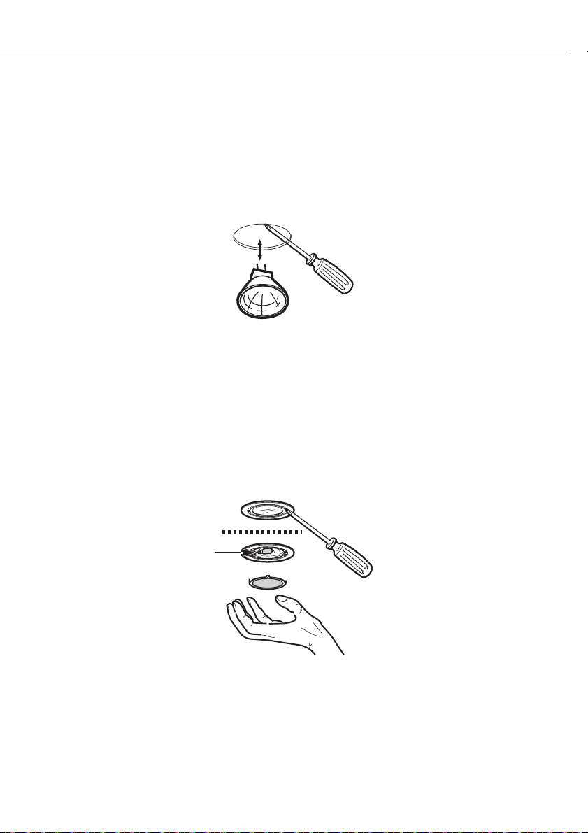
6.2 SOSTITUZIONE DELLA LAMPADA DICROICA
ATTENZIONE
Scollegare la cappa dall’alimentazione elettrica ed assicurarsi che le luci siano fredde.
Se le nuove luci non funzionano, assicurarsi che la lampadina sia stata inserita correttamente prima
di rivolgersi all’Assistenza.
Per lampadine tipo GU4/MR11 12V 20W; modelli cappe ALA, ALL, APN, ASU e ASL
Per lampadine tipo GU5/MR16 12V 20W; modelli cappe AHZ e ATI
- Servirsi di un piccolo cacciavite a testa piatta o di un attrezzo equivalente per fare leva delicatamente sulla lampadina, scollegandola dai morsetti a molla nella presa. Fare attenzione a non gra are la
parte inferiore della cappa.
- Per rimuovere la lampadina, tirarla verso il basso.
- Veri care l’orientamento della lampadina nella presa prima di inserire la lampadina nuova. Spingere verso l’alto no a quando la lampadina si innesta nella presa e nei morsetti a molla. La lampadina
sostitutiva deve avere una lente di sicurezza fusa termicamente “adatta all’uso in apparecchi di
illuminazione aperti”.
Per lampadine tipo G4 12V 20W; modelli cappe ADU, ADL e AED
6. Manutenzione
- Utilizzare un piccolo cacciavite a testa piatta o un attrezzo equivalente per fare leva delicatamente
sul coprilampada. Fare attenzione a non gra are la parte inferiore della cappa.
- Togliere la lampadina non funzionante e sostituirla con una nuova “adatta all’uso in apparecchi di
illuminazione aperti”. Seguire le istruzioni riportate sulla confezione e non toccare la nuova lampadina a mani nude.
- Reinserire il coprilampada.
- 51 -
Page 52

3LIK0516
 Loading...