

Page 1
ALU-E43BSX
ALU-E43BWX
ALU-E63BSX
ALU-E63BWX
www.zephyronline.com
Use, Care, and Installation Guide
OCT19.0201 © Zephyr Ventilation LLC.
Page 2

- 2 -
Page 3

Table of contents
Safety Instructions................................................ Page 4 - 5
List of Materials.................................................... Page 6
Ducting Calculation Sheet.................................... Page 7
Hood Specifi cations.............................................. Page 8
Wiring Diagram..................................................... Page 9 - 10
Cleaning and Maintenance................................... Page 11
Remote Control.................................................... Page 12
Hood Controls...................................................... Page 13 - 14
Installation
Remote Blower Ductwork............................... Page 15
Internal Blower Ductwork............................... Page 16
Installation Preparation................................... Page 17 - 18
Installation Internal Blower............................. Page 19 - 20
Installation Remote Blower........................... Page 21 - 22
Installing the Hood......................................... Page 23
Non-Ducted Recirculation Kit......................... Page 24
Mesh Filters.................................................... Page 25
List of Parts & Accessories................................... Page 26
Warranty............................................................... Page 27
Product Registration............................................. Page 28
- 3 -
Page 4
READ AND SAVE THESE INSTRUCTIONS
!
INTENDED FOR DOMESTIC COOKING ONLY
!
WARNING
TO REDUCE THE RISK OF FIRE OR ELECTRIC SHOCK, DO NOT USE THIS FAN WITH ANY SOLID-STATE CONTROL DEVICE.
WARNING
TO REDUCE THE RISK OF FIRE ELECTRIC SHOCK, OR INJURY TO PERSONS, OBSERVE THE FOLLOWING:
a. Use this unit only in the manner intended by the manufacturer, if you have questions, contact the manufacturer.
b. Before servicing or cleaning unit, switch power
When the service disconnecting means cannot be locked, securely fasten a prominent warning device, such as a tag, to the service
panel.
CAUTION
For general ventilating use only. Do not use to exhaust hazardous or explosive materials and vapors. Take care when using cleaning
agents or detergents. Suitable for use in household cooking area.
WARNING
TO REDUCE THE RISK OF RANGE TOP GREASE FIRE:
a. Never leave surface units unattended at high settings. Boilovers cause smoking and greasy spillovers that may ignite. Heat oils slowly
on low or medium settings.
b. Always turn hood ON when cooking at high heat or when
c. Clean ventilating fans frequently. Grease should not be allowed to accumulate on fan or
d. Use proper pan size. Always use cookware appropriate for the size of the surface element.
e. Keep fan,
f. Use high setting on hood only when necessary.
g. Don’t leave hood unattended when cooking.
h. Always use cookware and utensils appropriate for the type of and amount of food being prepared.
and grease laden surfaces clean.
at service panel and lock panel to prevent power from being switched on accidentally.
food
WARNING
TO REDUCE THE RISK OF INJURY TO PERSONS IN THE EVENT OF A RANGE TOP FIRE, OBSERVE THE FOLLOWING:
a. SMOTHER FLAMES with a
If the
b. NEVER PICK UP A FLAMING PAN – You may be burned.
c. DO NOT USE WATER, including wet dishcloths or towels – a violent steam explosion will result.
d. Use an extinguisher ONLY if:
1. You know you have a Class ABC extinguisher, and you already know how to operate it.
2. The
3. The
4. You can
do not go out immediately, EVACUATE AND CALL THE FIRE DEPARTMENT.
is small and contained in the area where it started.
department is being called.
the with your back to an exit
lid, cookie sheet, or metal tray, then turn the burner. BE CAREFUL TO PREVENT BURNS.
WARNING
TO REDUCE THE RISK OF FIRE, ELECTRIC SHOCK OR INJURY TO PERSONS, OBSERVE THE FOLLOWING:
a. Installation work and electrical wiring must be done by
Including
air is needed for power combustion and exhausting of gases through the (chimney) of fuel burning equipment to prevent
back-drafting. Follow the heating equipment manufacturer’s guideline and safety standards such as those published by the National
Fire Protection Association (NFPA) and the American Society for Heating, Refrigeration and Air Conditioning Engineers (ASHRAE) and
the local code authorities.
c. When cutting or drilling into wall or ceiling, do not damage electrical wiring and other hidden utilities.
d. Ducted fans must always vent to the outdoors.
e. NEVER place a switch where it can be reached from a tub or shower.
f. Make sure the power is
construction.
before installing, wiring or maintenancing.
person(s) in accordance with all applicable codes and standards.
Prop. 65 Warning for California Residents
WARNING: This product may contain chemicals known to the State of California to cause cancer, birth
- 4 -
Page 5
WARNING
TO REDUCE THE RISK OF FIRE, USE ONLY METAL DUCTWORK.
CAUTION
attics, crawl spaces or garages.
OPERATION
and loose clothing.
The manufacturer declines all responsibility in the event of failure to observe the instructions given here for installation,
maintenance and suitable use of the product. The manufacturer further declines all responsibility for injury due to
negligence and the warranty of the unit automatically expires due to improper maintenance.
*NOTE: Please check www.zephyronline.com for revisions before doing any custom work.
ELECTRICAL REQUIREMENTS
Important:
Observe all governing codes and ordinances.
It is the customer’s responsibility:
-
- To assure that the electrical installation is adequate and in conformance with National Electrical Code, ANSI/NFPA 70
latest edition* or CSA standards C22.1-94, Canadian Electrical Code, Part 1 and C22.2 No.0-M91 - latest edition** and
all local codes and ordinances.
ground path is adequate.
Do not ground to a gas pipe.
Do not have a fuse in the neutral or ground circuit.
*National Fire Protection Association Batterymarch Park, Quincy, Massachusetts 02269
** CSA International 8501 East Pleasant Valley Road, Cleveland, Ohio 44131-5575
This appliance requires a 120V 60Hz electrical supply and connected to an individual properly grounded branch circuit
protected by a 15 or 20 ampere circuit breaker or time delay fuse. Wiring must be 2 wire with ground. Please also refer to
Electrical Diagram on product.
A cable locking connector (not supplied) might also be required by local codes. Check with local requirements, purchase
and install appropriate connector if necessary.
FEDERAL COMMUNICATION COMMISSION INTERFACE STATEMENT
This equipment has been tested and found to comply with the limits for a Class B digital device, pursuant to Part 15 of
the FCC Rules. These limits are designed to provide reasonable protection against harmful interference in a residential
installation.
This equipment generates, uses and can radiate radio frequency energy and, if not installed and used in accordance
with the instructions, may cause harmful interference to radio communications. However, there is no guarantee that
interference will not occur in a particular installation. If this equipment does cause harmful interference to radio or
the interference by one of the following measures:
. Reorient or relocate the receiving antenna.
. Increase the separation between the equipment and receiver.
. Consult the dealer or an experienced radio/TV technician for help
- 5 -
Page 6
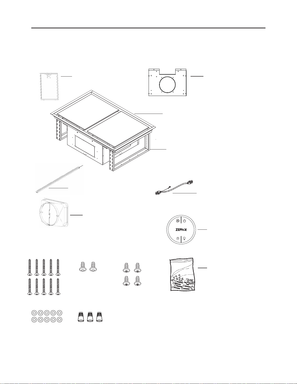
LIST OF MATERIALS
MODELS: ALU-E43BSX, ALU-E63BSX
ALU-E43BWX, ALU-E63BWX
PARTS SUPPLIED
(4) Aluminum mesh lters
(6 - for 63” model)
(3) LED light strips (4 - for 63” model)
(1) 10” round duct collar
(1) CBI Single Internal
Blower Bracket
(1) Hood Body
(2) Support frame arms
(1) Remote blower wiring harness
HARDWARE PACKAGE CONTENTS
#6 x 2” (10)
5 x 12 x 1T (10)
PARTS NOT SUPPLIED
- Internal, In-Line or External Blowers
- Ducting, conduit and all installation tools
- Cable connector (if required by local codes)
- Recirculating kit accessory
3/16 x 1/2” (2) M4 x 8 (4)
Wire Caps (3)
(1) RF remote control
(1) Hardware package
- 6 -
Page 7
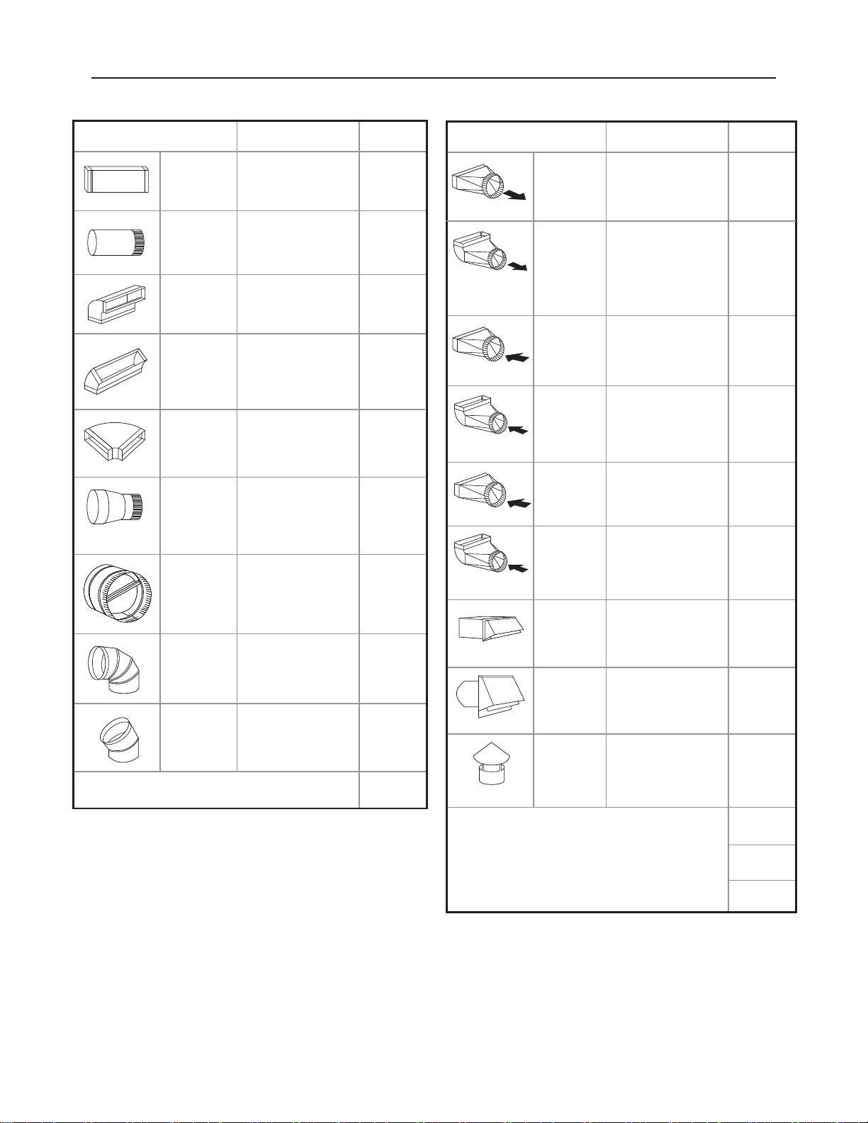
DUCTING CALCULATION SHEET
Duct pieces
3- 1/ 4” x 10”
Rect.,
straight
6”, 7”, 8”, 10”
Round,
straight
3- 1/ 4” x 10”
0
Rect. 90
elbow
3- 1/ 4” x 10”
0
Rect. 45
elbow
3- 1/ 4” x 10”
0
Rect. 90
flat elbow
7” to 6” or
8” to 7” Round
tapered
reducer
6”, 7“, 8”
Round
in-line
damper
6”, 7”, 8”, 10”
Round,
0
90
elbow
6”, 7”, 8”, 10”
Round,
0
45
elbow
Equivalent number
length x used =
1 Ft. x ( ) =
1 Ft. x ( ) =
15 Ft. x ( ) =
9 Ft. x ( ) =
24 Ft. x ( ) =
25 Ft. x ( ) =
15
Ft. x ( ) =
15 Ft.
x ( ) =
9 Ft. x ( ) =
Subtotal column 1 =
To t a l
Ft.
Ft.
Ft.
Ft.
Ft.
Ft.
Ft.
Ft.
Ft.
Ft.
Duct pieces
3- 1/ 4” x 10”
Rect. to
6” round
transition
3- 1/ 4” x 10”
Rect. to
6” round
transition
0
elbow
90
6” round to
3- 1/ 4” x 10”
rect.
transition
6” round to
3- 1/ 4” x 10”
rect.
transition
0
elbow
90
7” round to
3 1/ 4” x 10”
rect.
transition
7” round to
3- 1/ 4” x 10”
rect.
transition
0
elbow
90
3- 1/ 4” x 10”
Rect.
wall cap
with damper
6”, 7”, 8”, 10”
Round, wall
cap with
damper
6”, 7”, 8”, 10”
Round
roof cap
Equivalent number
length x used =
5 Ft. x ( ) =
20 Ft. x ( ) =
1 Ft. x ( ) =
16 Ft. x ( ) =
8 Ft. x ( ) =
23 Ft. x ( ) =
30 Ft. x ( ) =
30 Ft. x ( ) =
30 Ft. x ( ) =
To t a l
Ft.
Ft.
Ft.
Ft.
Ft.
Ft.
Ft.
Ft.
Ft.
Maximum Duct Length: For satisfactory air movement,
the total duct length
should not exceed 100 equivalent feet.
- 7 -
Subtotal column 2 =
Subtotal column 1 =
Total ductwork =
Ft.
Ft.
Ft.
Page 8
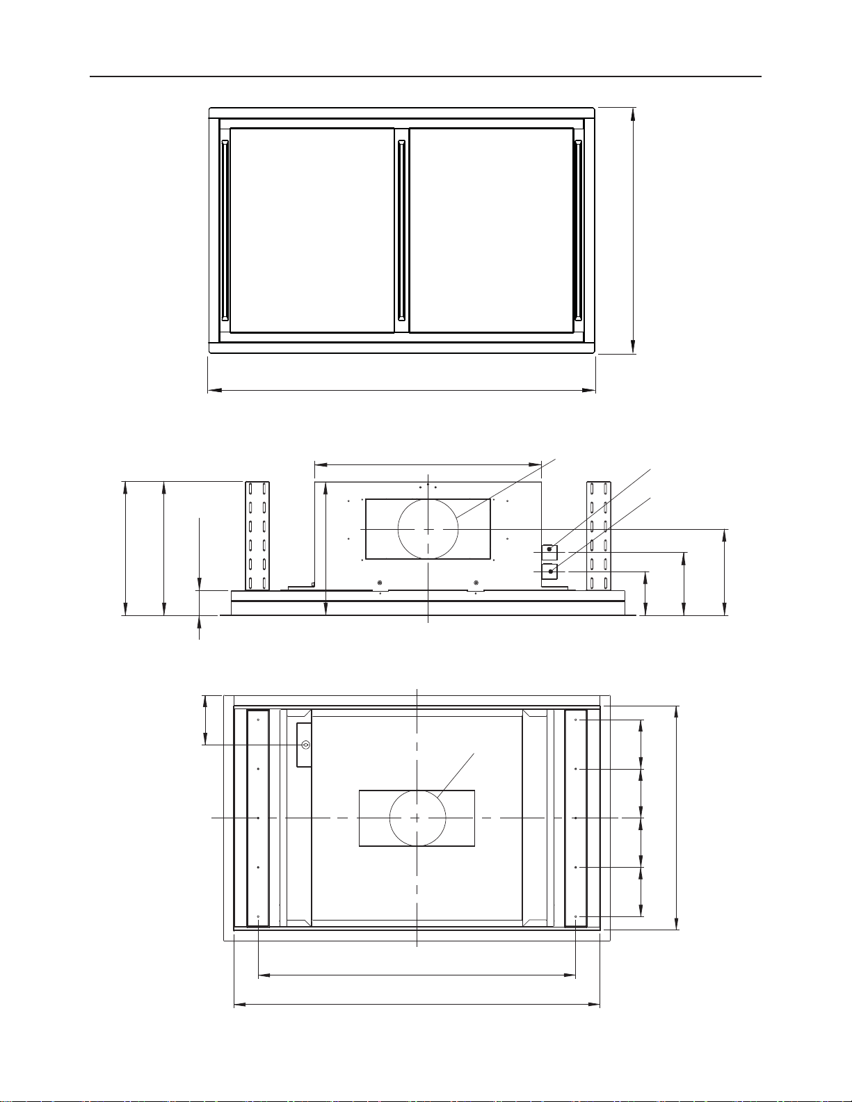
HOOD SPECIFICATIONS
27-9/16”
43-5/16”, 63-1/2”
2-5/8”
Min. 14”
Max. 23-3/4”
5-9/16”
23-5/8”
13-15/16”
C/L
6” Round or
10” Round
6” Round or
10” Round
Remote Blower
Junction Box
AC Power
Junction Box
6-1/2”
4-1/2”
9”
35-9/16”
41”, 61-1/4”
- 8 -
25-3/16”
5-1/2” 5-1/2” 5-1/2”
5-1/2”
Page 9
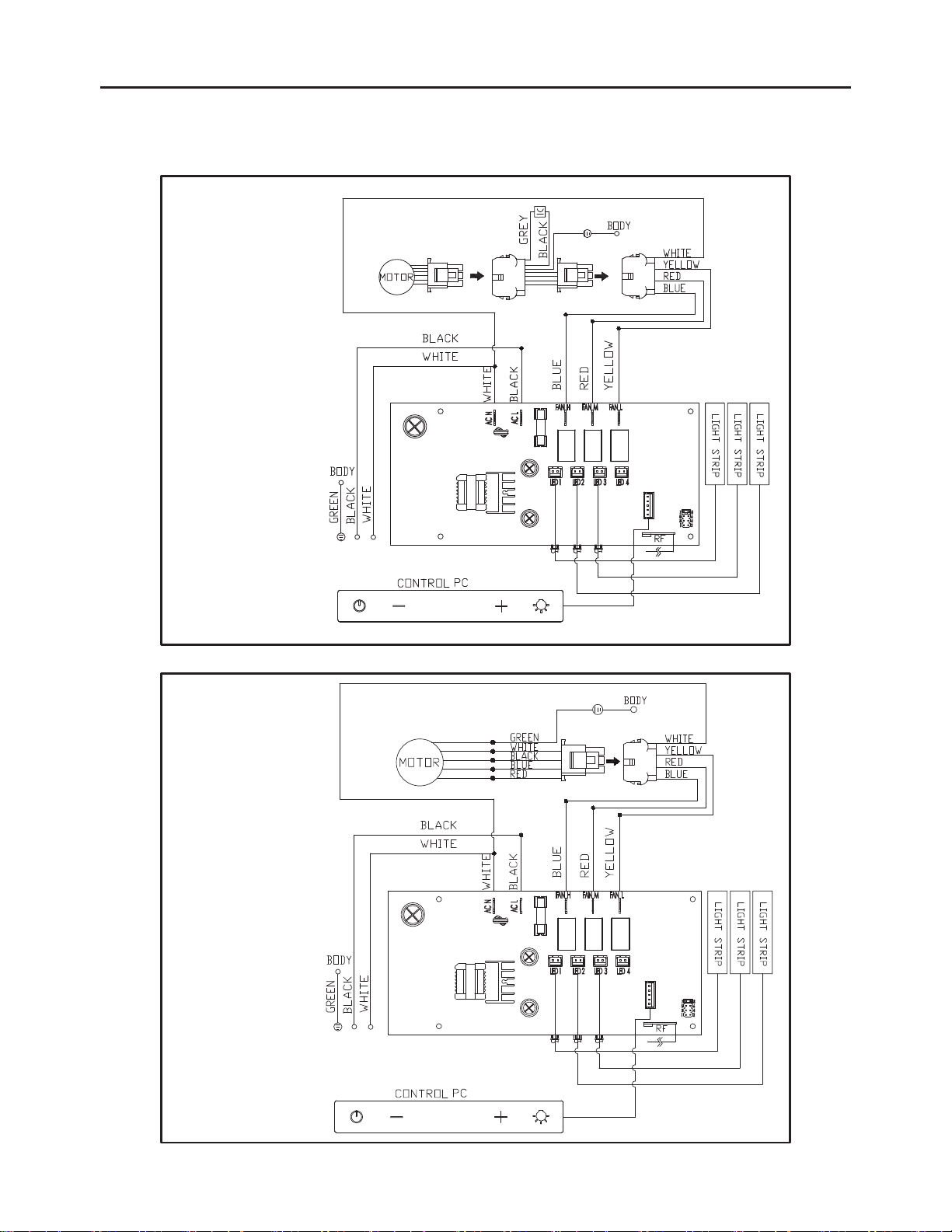
WIRING DIAGRAM
ALU-E43BSX, ALU-E43BWX
Internal Blower External / In-Line Blower
Blower Models: CBI-600A, CBI-290A, PBI-1100A Blower Models: CBE-1000, PBN-1000A
- 9 -
Page 10
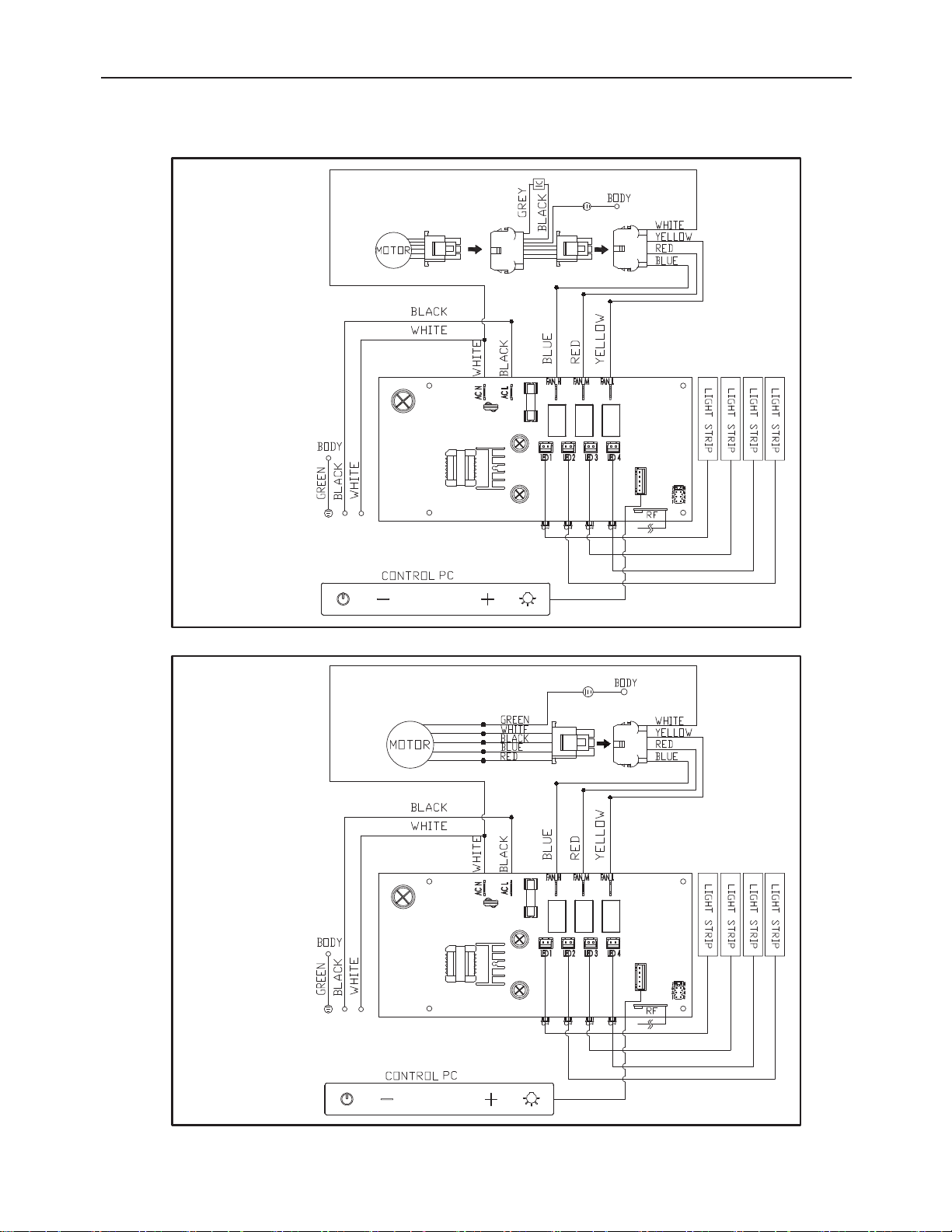
WIRING DIAGRAM
ALU-E63BSX, ALU-E63BWX
Internal Blower External / In-Line Blower
Blower Models: CBI-600A, CBI-290A, PBI-1100A Blower Models: CBE-1000, PBN-1000A
- 10 -
Page 11

CLEANING AND MAINTENANCE
Proper maintenance of the Range Hood will assure proper performance of the unit.
Motor
The motor is permanently lubricated and never needs oiling. If the motor bearings make
excessive or unusual noise, replace the motor with the exact service motor. The impeller
should also be replaced.
Mesh Filters
The mesh filters should be cleaned frequently. Using warm water with detergent. Mesh
filters are dishwasher safe.
Clean all-mesh filters in the dishwasher using a non-phosphate detergent. Discoloration of
the filter may occur if using phosphate detergents, or as a result of local water conditions but this will not affect filter performance. This discoloration is not covered by the warranty.
See “MESH FILTERS” section for removal and installation instructions.
Non-ducted Charcoal Filter
The non-ducted charcoal filter should be changed every 6 months or when prompted on
the hood controls. Replace more often if your cooking style generates extra grease, such
as frying and wok cooking. See “MESH FILTERS” section for removal and installation
instructions.
LED Lighting
In the unlikely event that your LED strip fails, please contact Zephyr to order replacement
parts and schedule service.
Stainless Steel Cleaning
DO:
• Regularly wash with clean cloth or rag
soaked with warm water and mild soap or
liquid dish detergent.
• Always clean in the direction of original
polish lines.
• Always rinse well with clear water (2 or 3
times) after cleaning. Wipe dry completely.
• You may also use a specialized household
stainless steel cleaner.
Avoid: When choosing a detergent
• Any cleaners that contain bleach will attack stainless steel
• Any products containing: chloride, fluoride, iodide, bromide will deteriorate surfaces
rapidly.
• Any combustible products used for cleaning such as acetone, alcohol, ether, benzol, etc.,
are highly explosive and should never be used close to a range.
DON’T:
• Use any steel or stainless steel wool or
any other scrapers to remove stubborn dirt.
• Use any harsh or abrasive cleansers.
• Allow dirt to accumulate.
• Let plaster dust or any other construction
residues reach the hood. During construction/renovation, cover the range hood to
make sure no dust sticks to the stainless
steel surface.
- 11 -
Page 12
REMOTE CONTROL
FCC Caution: To assure continued compliance, any changes or modifications not expressly approved by the party responsible for compliance could void the user’s authority to operate this equipment. (Example - use only shielded interface cables when connecting to computer
or peripheral device. This device complies with Part 15 of the FCC Rules. Operation is subject to the following two conditions. (1) This device
may not cause harmful interference, and (2) This device must accept any interference received, including interference that may cause
undesired operation.
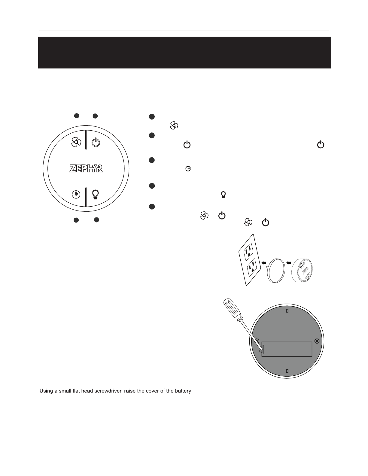
REMOTE PAIRING: To create a unique link between your hood and remote control please follow these steps:
1. With hood off, press and hold the “Lights” button on the hood until the lights button indicator blinks.
2. Press the “Blower On/ Power Off” button on the remote, the “Lights” button on the hood will stop blinking and the
synchronization is complete.
RF REMOTE FUNCTIONS:
Blower On/
Speed Selection
1
Blower On/
2
Power Off
1
Blower On / Speed Selection
Press to power on blower and cycle through all six blower speeds.
2
Blower On / Power Off
By pressing , the blowers will power on at the last speed setting. Press
again and the entire hood will power off, including lights.
Delay Off
3
By pressing , the blower and lights will enter Delay Off mode. The blower will
change to speed 1 and shut down after 10 minutes.
Lights On / Dim / Off
4
Switch lights On by pressing once, again to dim and again to switch Off.
Clean Air On / Off
5
10 Min Delay Off
CLEAN FILTER REMINDER RESET:
Mesh Filter Clean Reminder: With hood off, press and hold the “Blower On/
Speed Selection” button and “Lights” button simultaneously.
Charcoal Filter Clean Reminder: With hood off, press and hold the “Delay
Off” button and “Lights” button simultaneously.
3
4
Lights On/Dim/Off
With hood off, press and simultaneously to power on the clean air function.
To power off the clean air function, press and simultaneously with hood off.
RF REMOTE FEATURES:
The RF remote control is equipped with a magnet on the back for easy
storage. The remote may be placed on any magnetic surface such as a
refrigerator or the Zephyr remote holder, FIG. 1. The remote holder can
be inserted into a standard electrical outlet for easy storage. Note: The
remote holder does not charge the RF remote.
Maximum remote control communication distance is 15 feet from the hood.
RF REMOTE MAINTENANCE:
Clean the remote control using non abrasive detergents
+
FIG. 1
A
-
Follow instructions below for replacing battery.
door (A) in order to access the battery compartment. FIG. 2.
Remove the battery and replace with battery type A23 12V.
Negative end of battery should face the spring inside the remote.
Re-install battery door and recycle old battery.
- 12 -
FIG. 2
Page 13
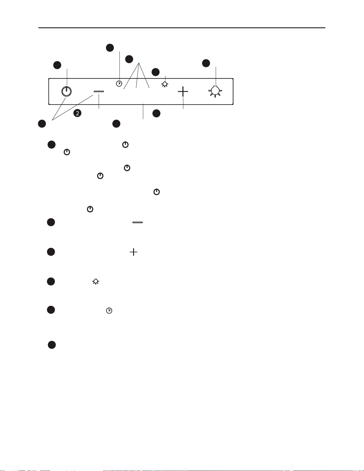
CONTROLS
Power / Delay Off
1
5
Delay Off Timer Indicator
6
Speed Indicators
8
Q 2 3
clean filters
Lights Indicator
Lights On/Off
4
Fan Speed Decrease
Clean Filter Indicator
Clean Air On / Off9
Power / Delay Off Button
1
- Button will turn power on and off for entire hood (fan and lights).
- Hood will remember the last speed and light level it was last turned off at.
(Example: Press button to turn off hood when on fan speed 3 and high lights.
Press button again and the hood will turn back on at speed 3 and high lights.
Delay Off
- With the fan on, press and hold the button for two seconds. The fan will change to speed 1 and the
10 minute delay off timer will start.
- Pressing Button while delay off function is enabled will turn the hood off and cancel the delay off function.
Fan Speed Decrease Button
2
- Press this button to decrease fan speed. 3, 2, Q (Quiet).
- If fan is off, press this button to turn on fan at last speed it was turned off at.
Fan Speed Increase Button
3
- Press this button to increase fan speed. Fan on, Q (Quiet), 2, 3.
- If fan is off, press this button to turn on fan at last speed it was turned off at.
Lights Button
4
- Lights are three levels, high, medium and low.
- From off, press one time for dim, two times to medium, three for high and four to power off again.
7
3
Fan Speed Increase
Delay Off Indicator
5
- When delay off function is activated, delay off indicator light will turn on indicating the delay off 10 minute
timer has started.
- After 5 minutes the fan, lights and delay off indicator will automatically turn off.
Speed Level Indicators
6
- Fan is three speed levels. Q (Quiet), 2, 3.
- 13 -
Page 14
CONTROLS
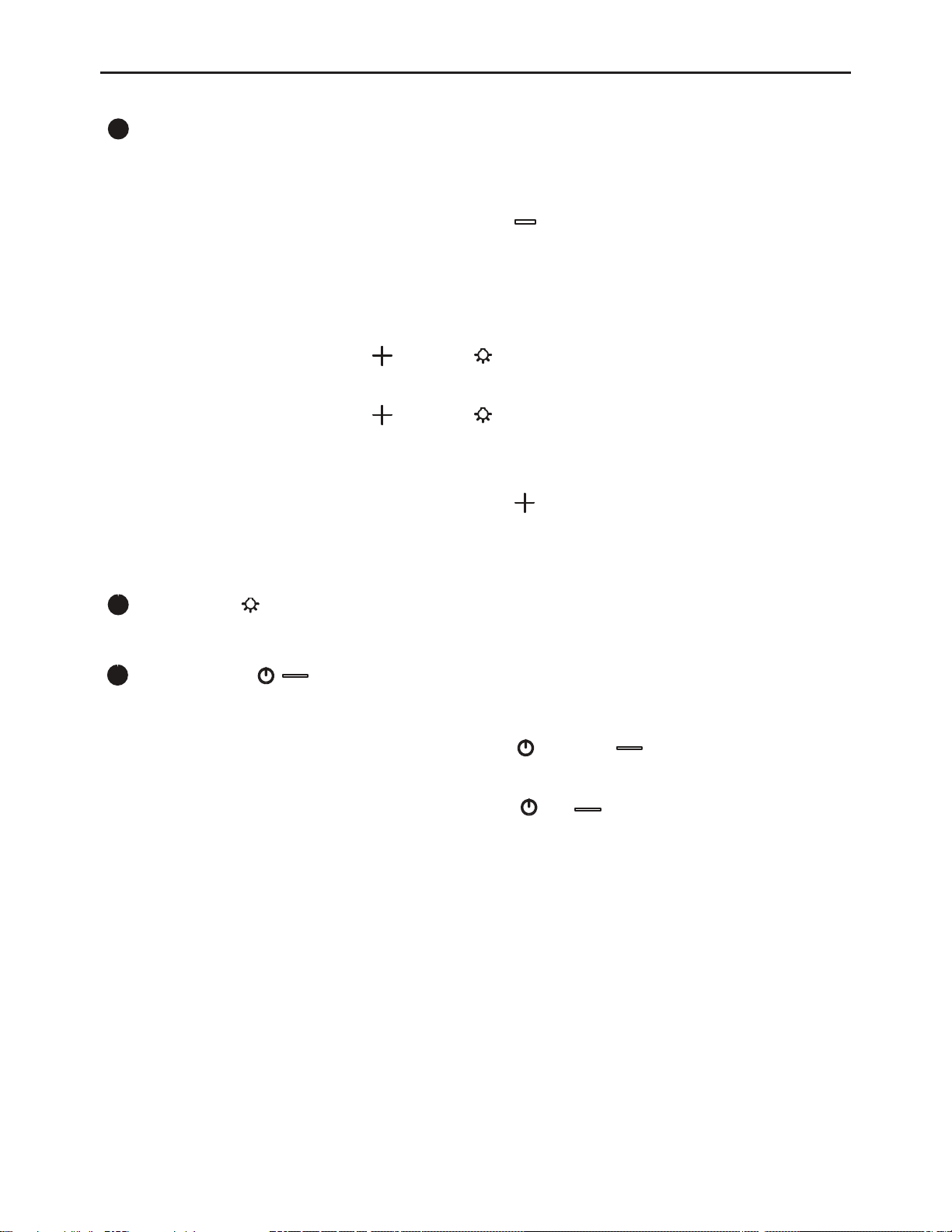
Clean Filters Indicator
7
Mesh Filter Clean Reminder (always enabled)
- After 120 hours of fan usage, the clean fitlers indicator will turn on and the two side LED light strips
will flash on and off indicating it is time to clean the mesh filters.
- To Reset with Hood Controls: With hood off: hold the button for three seconds. The clean filters
indicator will turn off confirming the 120 hour timer has been reset.
- To Reset with Remote Controls: With hood off: hold the Blower On/Speed Selection button and Lights
button simultaneously.
Charcoal Filter Replace Reminder (disabled by default, must be enabled if recirculating hood)
- To Enable Charcoal Filter Replace Indicator:
With hood off: press and hold the button and button simultaneously for three seconds. All LED
indicators will illuminate for three seconds confirming function enabled.
- To Disable Charcoal Filter Replace Indicator:
With hood off: press and hold the button and button simultaneously for three seconds. All LED
indicators will blink two times confirming function disabled.
- After 240 hours of fan usage, the clean fitlers indicator will turn on and all LED light strips will flash on and
off indicating it is time to replace the charcoal filters.
- To Reset with Hood Controls: With hood off: hold the button for three seconds. The clean filters indicator
will turn off confirming the 240 hour timer has been reset.
- To Reset with Remote Controls: With hood off: press and hold the Delay Off button and the Lights button
simultaneously.
Lights Indicator
8
- When lights are on high, medium or low, lights indicator will illuminate.
9
Clean Air On / Off
- Clean Air is a feature that turns the fan on every 4 hours for 10 minutes to remove stagnant air in the kitchen.
The Clean Air feature is disabled by default and must be enabled by the user.
- To enable Clean Air Function: With hood off, hold the button and button simultaneously for three
seconds. The LED indicators “Q, 1, 2, 3” will illuminate for 3 seconds and the fan will turn on speed 1 for
10 minutes. After 10 minutes, the fan will turn off and the 4 hour timer will begin.
- To disable Clean Air Function: With hood off, hold the and button simultaneously for three seconds.
The LED indicator “Q” will illuminate for 3 seconds indicating the function has been disabled.
- 14 -
Page 15
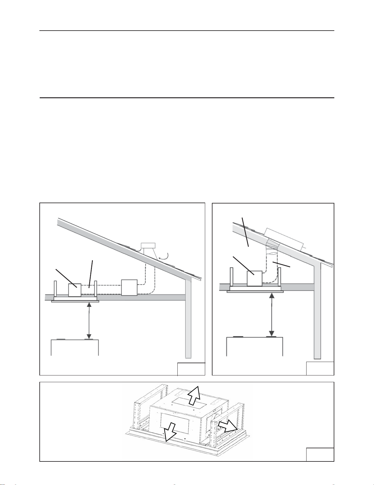
REMOTE BLOWERS (EXTERNAL AND IN-LINE)
CAUTION: To reduce risk of f ire and electric shock, install this range hood only with External
Blower Model CBE-1000, and In-Line Blower Model PBN-1000A. Other blowers cannot be
substituited.
INSTALLING THE DUCTWORK: REMOTE BLOWER
NOTE: To reduce the risk of fire, use only rigid metal ductwork.
1. Choose the location where the External Blower or In-Line Blower will be mounted. See
illustrations below for mounting location suggestions and restrictions. Choose the air outlet
location. See Fig. 3.
2. A straight, short duct run using a minimum 10” round duct will allow the hood to perform
most efficiently.
3. Long duct runs, elbows and transitions will reduce the performance of the hood. Use as
few of them as possible. Larger ducting may be required for best performance with long
duct runs.
4. After the External or In-Line Blower has been installed, connect round metal ductwork
and work back towards the hood location. Use duct tape to seal joints between ductwork
sections.
(blower
housing)
10” round duct
30” to 72” above
cooking surface
in-line
blower
Roof Pitch w/
Flashing & Cap
FIG. 1
Attic or crawl space
(blower
housing)
30” to 72”
above cooking
surface
external blower
10”
round
duct
FIG. 2
- 15 -
FIG. 3
Page 16
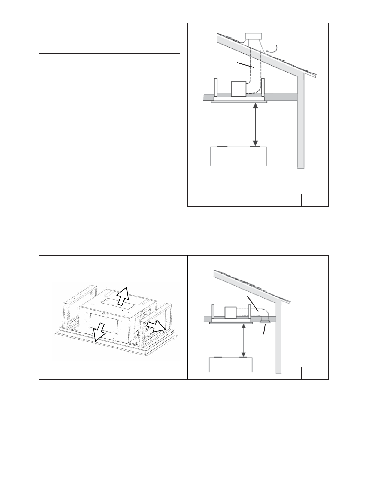
INSTALLING THE DUCTWORK:
INTERNAL BLOWER
NOTE: To reduce the risk of fire, use only
rigid metal ductwork.
1. Decide where the ductwork will run
between the hood and the outside.
2. A straight, short duct run using a minimum
6” round duct for single internal blower and
10” round duct for the dual internal blower
will allow the hood to perform most efficiently.
3. Long duct runs, elbows, and transitions will
reduce the performance of the hood. Use
as few of them as possible.
4. Install a roof cap. Connect round metal
ductwork to cap and work back towards
hood location. Use duct tape to seal the
joints between ductwork sections (Fig.4).
5. Choose blower outlet position desired. Blower
oulet options are from top, side or front of blower
housing. FIG. 5
6. Non-ducted recirculating only. 6” round ducting
must be connected from a single internal blower
to the air return vent. FIG. 6
ROOF CAP
6” or 10”
round duct *
30” to 72”
above cooking
surface
* 6” : hood with single internal blower
* 10” : hood with dual internal blower
FIG. 4
FIG. 5
Optional Recirculating Kit
6” round duct
30” to 72”
above cooking
surface
AIR
RETURN
VENT
FIG. 6
Air return vent must be a minimum of 6 feet from hood
Recirculating Kit ZRC-01LX is only compatible
with single internal blower models CBI-600A and
CBI-290A.
- 16 -
Page 17
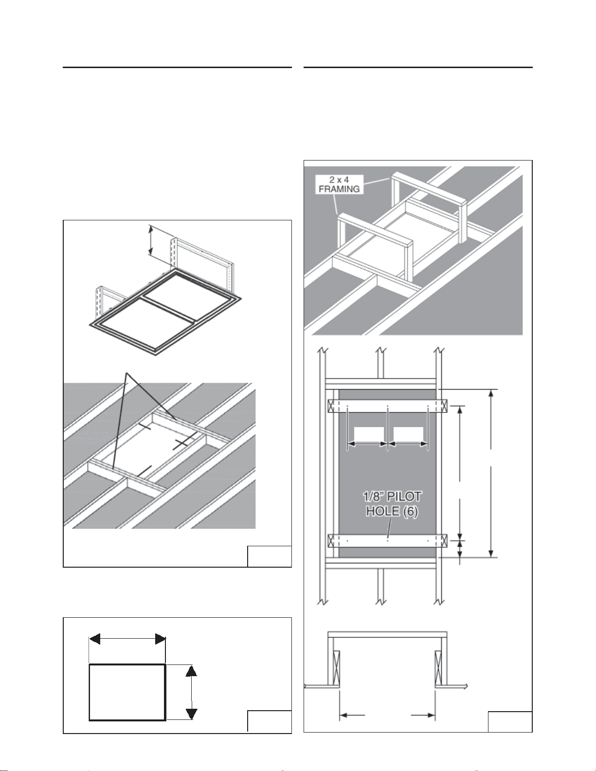
PREPARE THE CEILING OPENING
PREPARE THE HOOD SUPPORT
The hood should always be centered over the
cooktop. Make sure there is adequate space
in the ceiling structure to install the hood and
ductwork. The hood should be mounted 30”
to 72” above the cook top for best removal of
cooking impurities. Use joist size lumber to
frame in around the range hood opening. The
ceiling structure must be able to support the
weight of the hood. Fig 7.
Model ALU-E43 = 65 pounds.
Model ALU-E63 = 85 pounds.
min. 14”
max. 23-3/4”
Construct a wood framing system as shown
in Fig. 9.
The structure must be capable of supporting
its own weight, plus the weight of the hood.
Model ALU-E43 = 65 pounds.
Model ALU-E63 = 85 pounds.
DOUBLE HEADERS
A
B
Model ALU-E43: A= 25¾”, B=41-1/2”
Model ALU-E63: A= 25¾”, B=61-3/4”
For Non-Ducted version:
Make a cut-out in the ceiling for the air return
vent. See FIG. 8 below
16”
5-1/2”5-1/2”
B
35-9/16”
FIG. 7
15-7/8”
Air return vent must be a minimum of 6 feet from hood
FIG. 8
- 17 -
25-3/4”
14-15/16”
FIG. 9
Page 18

PREPARE THE HOOD
1. Push in lock tab behind center of perimeter panel to open. See FIG. 10.
1. Open the perimeter panels and remove the mesh filters. See FIG.11.
2. Remove the central panel/s unscrewing the 3/16 x 1/4 screws. See Fig.11.
3. Remove the (2) light panels by unscrewing the 3/16 x 1/4 screws (ALU-E43 model only). See Fig.12.
FIG.10
Model ALU-E43
REMOVE (4)
MOUNTING
SCREWS (3/16 x
1/4 Flat Head)
FIG.11
REMOVE (4+4)
MOUNTING
SCREWS (3/16 x
1/4 Flat Head)
- 18 -
FIG.12
Page 19

INSTALLATION INTERNAL BLOWER
NOTE: The following instructions are for
installing the internal blower only.
Install this range hood only with internal
blower model CBI-290A, CBI-600A or PBI-1100A
1. Choose blower ducting outlet. Duct options are from
top, side or front. FIG. 13
2. Remove knockout plate for only one chosen duct
outlet position. FIG. 14
3. Attach internal blower plate to CBI blower by (4) M4
x 16 mm screws provided with CBI blower. FIG. 15
4. Install internal blower with blower plate into hood
body. Bottom of blower plate hooks into body tabs.
Top of blower plate attaches by (2) 3/16 x 1/2” screws.
FIG. 16
FIG.13
FIG.14
FIG.15
Blower Plate Rests on Hook
FIG.16
- 19 -
Page 20

CONNECT THE WIRES (INTERNAL BLOWER)
Note: This range hood must be properly grounded. The unit should be installed by
a qualifi ed electrician in accordance with all applicable national and local electrical codes.
CBI-600A and CBI-290A Connection
1. Mount Capacitor box to hood body by (2) M4 x 8mm screws from blower hardware package.
2. Connect 6 pin female end from PCB box to 6 pin male end of capacitor box wiring. Connection A FIG. 17
3. Connect 9 pin male end from CBI blower to 9 pin female end of capacitor box wiring. Connection B FIG. 17
4. Connect green ground wire from capacitor box wiring to hood body by (1) 3/16 x 3/8 screw pre-installed
inside hood body. Connection C FIG. 17
A
C
From
CBI-600A or
B
CBI-290A
Blower
CBI-600A, CBI-290A Wiring
PBI-1100A Connection
1. Connect 6 pin female end from PCB box to 6 pin male end PBI-1100A blower wiring. Connection A FIG. 18
FIG.17
PBI-1100A Wiring
A
- 20 -
From
PBI-1100A
Blower
FIG.18
Page 21

INSTALLATION EXTERNAL
AND IN-LINE BLOWER
NOTE: The following instructions are for
preparing the hood for use with external
or in-line blower models CBE-1000 or PBN1000A. For blower installation details refer
to manual included with the blower.
1. Choose blower ducting outlet. Ducting options are
from top, side or front. FIG. 19
2. Remove knockout plate for only one chosen duct
outlet position. FIG. 20
3. Attach 10” round duct collar to desired outlet
position. FIG. 21
NOTE: Ducting through the side of the blower
housing and support frame may have restrictions
with 10” ducting. Support frame may restrict side
blower outlet. Please take support frame into
consideration and leave enough space between
support frame and the ducting.
FIG.19
FIG.20
FIG.21
- 21 -
Page 22

CONNECT THE WIRES (REMOTE BLOWER)
Note: This range hood must be properly grounded. The unit should be installed by a qualified electrician in
accordance with all applicable national and local electrical and building codes.
1. Connect 6 Pin Remote Blower Cable to 6 Pin molex plug from internal component box inside range hood.
FIG. 22
2. Run 5-wire power with ground cable from remote blower to the remote blower wiring box. FIG. 23
3. Connect the 5-wire power with ground from remote blower to remote blower cable wires. FIG. 24
CONNECTION AT REMOTE BLOWER
1. Make 5-wire power with ground connection at remote blower (see instructions providedd with remote
blower for further information.
A
5 Wire Connection
From Remote Blower
CBE-1000 / PBN-1000A: WIRING DIAGRAM
Remote Blower
Wiring Box
(hood)
White (common)
Black (high)
Blue (med)
Red (low)
Green (ground)
FIG. 22
FIG. 23
Junction Box
(Remote Blower)
FIG. 24
- 22 -
Page 23

INSTALLING THE HOOD
CAUTION: At least two installers are
recommended because of the large size
and weight of this range hood.
1. Lift range hood into the ceiling opening.
2. Secure each support frame to the wooden hood
support frame using (6 to 10) #6 x 2” screws with
washers provided. FIG. 25
3. Adjust height of the telescoping support frame to
ensure a tight fit between the hood and finished ceiling.
4. Connect ductwork; Duct tape all joints to ensure
an air tight seal.
5. Make all needed electrical connections.
6. Re-install the aluminum mesh filters, control
panel and light panels as needed.
CONNECT THE WIRES (POWER WIRES)
2x4 WOOD
FRAME
(6) WASHERS
& #6 x 2” SCREWS
FIG. 25
1. Remove a knockout from the wiring box input (Fig.26).
2. Secure the conduit to the wiring box through a conduit connector.
3. Make electrical connections. Connect white to white, black to black and green to ground.
4. Fix wiring box cover and screws (Fig.26). Make sure that wires are not pinched between
cover and box.
FIG. 26
- 23 -
Page 24

INSTALL THE AIR RETURN VENT
(NON-DUCTED VERSION)
Purchase the optional ZRC-01LX recirculating kit,
(sold separately). The kit includes the return air vent
and charcoal filter.
ZRC-01LX compatible with CBI-600A or CBI-290A
single internal blowers only.
1. Install the air return vent to the ceiling by (4) M4 x 31
screws. FIG. 28
2. Additional ceiling framing may be required
around air diverter to hold the weight of the vent.
See dimensional drawings if needed. FIG 29
2. Install charcoal filter behind air diverter panel.
3. Install air diverter panel. FIG. 27
6” Round Ducting
(purchased separately)
1. Fit back end of panel into push tab side
holding bracket
2. Pull opposite end forward and push up
3. Oposite end will catch on non push tab side
holding bracket
CEILING
16”
15-7/8”
(4) MOUNTING SCREWS
M4 x 31
FIG.27
Air Return Vent must be a minimum of 6 feet from hood
13-3/8”
18-1/8”
13-3/8”
17-1/16”
18-1/8”
1-9/16”
- 24 -
15-3/4”
Ø 6”
FIG.28
15-13/16”
FIG.29
Page 25

MESH FILTERS
NOTE: prior to use, remove protective film from the filter frame.
1. To remove the aluminum mesh filter, pull down on latch tab to disengage the filter from the hood.
Tilt the filter downward and remove.
2. To install the alumimum mesh filter, align rear filter tabs with slots in the hood. Pull latch tab
down. Push filter into place and release tab. Make sure the filter is securely engaged after installation.
Model ALU-E43
Model ALU-E63
FIG. 30
- 25 -
Page 26

LIST OF PARTS & ACCESSORIES
DESCRIPTION PART #
Replacement Parts
Aluminum Mesh Filter 50200046
Replacement Charcoal Filter Z0F-C002
LED Light Strip, 10W Z0B-0044
Remote Control 14000005
Remote Control Battery A23 12V 15000007
Optional Accessories
Recirculating Kit ZRC-01LX
Single Internal Blower, 290 CFM CBI-290A
Single Internal Blower, 600 CFM CBI-600A
Dual Internal Blower, 1100 CFM PBI-1100A
In-Line Blower, 1000 CFM PBN-1000A
External Blower, 1000 CFM CBE-1000
To order parts, visit us online at http://store.zephyronline.com or call us at 1.888.880.8368
- 26 -
Page 27

Zephyr Ventilation, LLC (referred to herein as “we” or “us”) warrants to the original consumer purchaser (referred to herein
as “you” or “your”) of Zephyr products (the “Products”) that such Products will be free from defects in materials or
workmanship as follows:
One Year Limited Warranty for Parts: For one year from the date of your original purchase of the Products, we will provide,
free of charge, Products or parts (including LED light bulbs, if applicable) to replace those that failed due to manufacturing
defects subject to the exclusions and limitations below. We may choose, in our sole discretion, to repair or replace parts
before we elect to replace the Products.
One Year Limited Warranty for Labor: For one year from the date of your original
provide, free of charge, the labor cost associated with repairing the Products or parts to replace those that failed due to
manufacturing defects subject to the exclusions and limitations below. After the first year from the date of your original
purchase, you are responsible for all labor costs associated with this warranty.
Warranty Exclusions: This warranty covers only repair or replacement, at our option, of defective Products or parts and
does not cover any other costs related to the Products including but not limited to: (a) normal maintenance and service
required for the Products and consumable parts such as fluorescent, incandescent or halogen light bulbs, mesh and charcoal filters and fuses; (b) any Products or parts which have been sub
faulty installation or installation contrary to recommended installation instructions, improper maintenance or repair (other
than by us); (c) commercial or government use of the Products or use otherwise inconsistent with its intended purpose; (d)
natural wear of the finish of the Products or wear caused by improper maintenance, use of corrosive and abrasive cleaning
products, pads, and oven cleaner products; (e) chips, dents or cracks caused by abuse or misuse of the Products; (f) service
trips to your home to teach you how to use the Products; (g) damage to the Products caused by accident, fire, floods, acts
of God; or (h) Custom installations or alterations that impact serviceability of the Products. If you are outside our service
area, additional charges may apply for shipping costs for warranty repair at our
travel cost to have a service technician come to your home to repair, remove or reinstall the Products. After the first year
from the date of your original purchase, you are also responsible for all labor costs associated with this warranty. All Products
must be installed by a qualified professional installer to be eligible for warranty repairs or service.
Limitations of Warranty. OUR OBLIGATION TO REPAIR OR REPLACE, AT OUR OPTION, SHALL BE YOUR SOLE
AND EXCLUSIVE REMEDY UNDER THIS WARRANTY. WE SHALL NOT BE LIABLE FOR INCIDENTAL,
CONSEQUENTIAL OR SPECIAL DAMAGES ARISING OUT OF OR IN CONNECTION WITH THE USE OR
PERFORMANCE OF THE PRODUCTS. THE EXPRESS WARRANTIES IN THE PRECEDING SECTION ARE
EXCLUSIVE AND IN LIEU OF ALL OTHER EXPRESS WARRANTIES. WE HEREBY DISCLAIM AND EXCLUDE
OTHER EXPRESS WARRANTIES FOR THE PRODUCTS, AND DISCLAIM AND EXCLUDE ALL WARRANTIES
IMPLIED BY LAW, INCLUDING THOSE OF MERCHANTABILITY AND FITNESS FOR A PARTICULAR PURPOSE.
Some states or provinces do not allow limitations on the duration of an implied warranty or the exclusion or limitation of
incidental or consequential damages, so the above limitations or exclusions may not apply to you. To the extent that
applicable law prohibits the exclusion of implied warranties, the duration of any applicable implied warranty is limited to the
same one-year and one-year periods described above if permitted by applicable law. Any oral or written description of the
Products is for the sole purpose of identifying the Products and shall not be construed as an express warranty. Prior to
using, implementing or permitting use of
use, and you shall assume all risk and liability whatsoever in connection with such determination. We reserve the right to
use functionally equivalent refurbished or reconditioned parts or Products as warranty replacements or as part of warranty
service. This warranty is not transferable from the original purchaser and only applies to the consumer residence where the
Product was originally installed located in the United States and Canada. This warranty is not extended to resellers.
To Obtain Service Under Limited Warranty:
telephone number stated below within 60 days of the discovery of the defect; (b) give the model number and serial number;
and (c) describe the nature of any defect
present evidence of your proof of purchase and proof of the original purchase date. If we determine that the warranty
exclusions listed above apply or if you fail to provide the necessary documentation to obtain service, you will be responsible
for all shipping, travel, labor and other costs related to the services. This warranty is not extended or restarted upon warranty
repair or replacements.
Please check our website for any additional Product information, www.zephyronline.com.
Zephyr Ventilation Service Department, 2277 Harbor Bay Parkway, Alameda, CA 94502 1-888-880-8368
the Products, you shall determine the suitability of the Products for the intended
To qualify for warranty service, you must: (a) notify us at the address or
in the Product or part. At the time of the request for warranty service, you must
ject to freight damage, misuse, negligence, accident,
purchase of the Products, we will
designated service locations and for the
ALL
OCT17.0301
- 27 -
Page 28

PRODUCT REGISTRATION
Congratulations on your Zephyr range
hood purchase! Please take a moment to
register your new range hood at
www.zephyronline.com/registration
IT’S IMPORTANT
Prompt registration helps in more ways
than one.
Ensures warranty coverage should you
need service.
Ownership verification for insurance
purposes.
Notification of product changes or recalls.
Zephyr Ventilation | 2277 Harbor Bay Pkwy. | Alameda, CA 94502 | 1.888.880.8368
- 28 -
Page 29

ALU-E43BSX
ALU-E43BWX
ALU-E63BSX
ALU-E63BWX
www.zephyronline.com
Guide d’utilisation, d’entretien et d’installation
OCT19.0201 © Zephyr Ventilation LLC.
Page 30

- 2 -
Page 31

Table des matières
Consignes de sécurité.......................................... Page 4 - 5
Liste du matériel................................................... Page 6
Feuille de calcul pour le conduit d’aération.......... Page 7
Spécifications de la hotte..................................... Page 8
Schéma de câblage.............................................. Page 9 - 10
Nettoyage et entretien.......................................... Page 11
Commande à distance......................................... Page 12
Commandes de la hotte....................................... Page 13 - 14
Installation
Conduit pour le ventilateur à distance............ Page 15
Conduit pour le ventilateur intérieur............... Page 16
Préparation de l’installation............................ Page 17 - 18
Installation d’un ventilateur à distance........... Page 19 - 20
Installation d’un ventilateur intérieur............. Page 21 - 22
Installation de la hotte.................................... Page 23
Trousse de reprise d’air sans conduit............ Page 24
Filtres à tamis................................................. Page 25
Liste des pièces et des accessoires...................... Page 26
Garantie................................................................ Page 27
Enregistrment du produit....................................... Page 28
- 3 -
Page 32

LISEZ ET CONSERVEZ CES INSTRUCTIONS
!
APPAREIL CONÇU POUR UNE UTILISATION MÉNAGÈRE SEULEMENT
!
AVERTISSEMENT
POUR RÉDUIRE LES RISQUES D’INCENDIE OU DE DÉCHARGE ÉLECTRIQUE, N’UTILISEZ PAS CET APPAREIL AVEC UN TABLEAU
DE COMMANDE À SEMI-CONDUCTEURS.
AVERTISSEMENT
POUR RÉDUIRE LES RISQUES D’INCENDIE, DE DÉCHARGE ÉLECTRIQUE OU DE BLESSURE, RESPECTEZ LES CONSIGNES SUIVANTES :
a. N’utilisez cet appareil que de la manière prévue par le fabricant. Si vous avez des questions, communiquez avec le fabricant.
b. Avant de procéder au nettoyage ou à l’entretien de l’appareil, éteignez l’alimentation du panneau électrique et bloquez le dispositif de
déconnexion pour éviter que l’alimentation électrique ne soit accidentellement rallumée. Si le dispositif de sectionnement d’électricité ne
peut être bloqué, mettez un avertissement (comme une étiquette) bien en vue sur le tableau électrique.
ATTENTION
Pour ventilation générale seulement. N’utilisez pas cet appareil pour évacuer des vapeurs et des matériaux explosifs ou dangereux. Prenez
garde lors de l’utilisation d’agents nettoyants ou de détergents. Cet appareil ne doit être utilisé que dans la cuisine de votre maison.
AVERTISSEMENT
POUR RÉDUIRE LES RISQUES DE FEU DE GRAISSE SUR LA SURFACE DE CUISSON :
a. Ne laissez jamais l’appareil sans surveillance lors de son utilisation à haute température. Les débordements par bouillonnement causent
de la fumée et des déversements de graisse qui peuvent prendre feu. Faites chauffer l’huile à des températures basses ou moyennes.
b. Allumez toujours la hotte lorsque vous cuisinez à haute température ou lorsque vous faites flamber des aliments.
c. Nettoyez fréquemment les ventilateurs de la hotte. La graisse ne devrait jamais s’accumuler dans les ventilateurs ou filtres.
d. Utilisez des poêlons aux dimensions adéquates. Utilisez toujours une batterie de cuisine correspondant aux dimensions de l’élément.
e. Assurez-vous que le ventilateur, les filtres et les surfaces où la graisse pourrait s’accumuler sont toujours propres.
f. Utilisez le réglage maximal de la hotte seulement lorsqu’il le faut.
g. Ne laissez pas la hotte sans surveillance lorsque vous cuisinez.
h. Utilisez toujours une batterie de cuisine et des ustensiles convenant au type et à la quantité de nourriture que vous préparez.
AVERTISSEMENT
POUR RÉDUIRE LES RISQUES DE BLESSURE LORS D’UN INCENDIE SUR LA SURFACE DE CUISSON :
a. ÉTOUFFEZ LES FLAMMES avec un couvercle, une plaque à biscuits ou un plateau de métal et éteignez ensuite le brûleur. PRENEZ
GARDE AUX RISQUES DE BRÛLURE. Si les flammes ne disparaissent pas, ÉVACUEZ LES LIEUX ET APPELEZ LE SERVICE
D’INCENDIE.
b. Pour éviter de vous brûler, NE PRENEZ JAMAIS UN POÊLON EN FEU.
c. N’UTILISEZ PAS DE L’EAU ou un linge à vaisselle mouillé, sans quoi une violente explosion de vapeur s’ensuivra.
d. Utilisez un extincteur SEULEMENT si :
1. vous possédez un extincteur de classe ABC et vous savez vous en servir;
2. le feu est faible et ne s’est pas répandu depuis son point d’origine;
3. vous avez appelé le service d’incendie;
4. vous pouvez sortir facilement de l’endroit où vous combattez le feu.
AVERTISSEMENT
POUR RÉDUIRE LES RISQUES D’INCENDIE, DE DÉCHARGE ÉLECTRIQUE OU DE BLESSURE, SUIVEZ LES CONSIGNES SUIVANTES :
a. Les travaux d’installation et de câblage électrique doivent être faits par une personne qualifiée selon les stipulations de tous les normes et
standards en vigueur, dont les normes des constructions ayant une cote de résistance au feu.
b. Une certaine quantité d’air est nécessaire pour la combustion et l’évacuation des gaz par le carneau (cheminée), ce qui prévient les
contre-explosions. Respectez les directives du fabricant de matériel dégageant de la chaleur et diverses normes de sécurité, notamment
celles publiées par la NFPA (Association nationale des services d’incendie) et par la Société américaine des ingénieurs en chauffage,
réfrigération et climatisation (ASHRAE), ainsi que les normes des autorités locales.
c. Lorsque vous coupez ou percez un mur ou un plafond, assurez-vous de ne pas endommager le câblage électrique ou toute autre installation
technique dissimulée.
d. Les ventilateurs canalisés doivent toujours évacuer l’air à l’extérieur.
e. N’installez JAMAIS un interrupteur à une distance à portée de la main depuis un bain ou une douche.
f. Assurez-vous que l’alimentation électrique est éteinte avant de procéder à l’installation, au câblage ou à l’entretien de l’appareil.
Prop. 65 Avertissement pour les résidents californiens
AVERTISSEMENT:
Cancer et troubles de l’appareil reproducteur
www.P65Warnings.ca.gov
- 4 -
Page 33

AVERTISSEMENT
POUR RÉDUIRE LES RISQUES D’INCENDIE, N’UTILISEZ QUE DES CONDUITS MÉTALLIQUES.
ATTENTION
Pour réduire les risques d’incendie et pour évacuer l’air convenablement, assurez-vous de canaliser l’air à l’extérieur de
la maison. N’installez pas l’échappement du conduit dans les espaces entre les murs, le plafond, le grenier, les vides
sanitaires ou le garage.
FONCTIONNEMENT
Laissez toujours les grilles de sûreté et les filtres en place. Sans ces éléments, des cheveux, des doigts ou des vêtements
amples pourraient s’accrocher dans le ventilateur pendant son fonctionnement.
Le fabricant se dégage de toute responsabilité dans les cas du non-respect des instructions transmises dans le présent
manuel d’installation, d’entretien et d’utilisation. Le fabricant se dégage également de toute responsabilité pour les blessures
résultant de négligence lors de l’utilisation. De plus, la garantie prend fin automatiquement lors de l’entretien inapproprié de
l’appareil.
*NOTE : Veuillez consulter les révisions sur le site www.zephyronline.com avant de procéder à tout travail sur commande.
EXIGENCES ÉLECTRIQUES
Important:
Respectez tous les codes et règlements en vigueur.
Il est de la responsabilité du client de :
- communiquer avec un installateur-électricien qualifié;
- s’assurer que l’installation électrique est adéquate, et qu’elle respecte le Code national de l’électricité, la plus récente
édition* de l’ANSI/NFPA 70 ou des normes du CSA C22.1-94, le Code canadien de l’électricité, section 1, la plus récente
édition** du code C22.2 No.0-M91, ainsi que tous les codes et règlements en vigueur.
Si les codes permettent l’utilisation d’un câble de garde isolé et que vous en utilisez un, il est recommandé qu’un électricien
qualifié détermine si le parcours du câble est adéquat.
N’effectuez pas la mise à la terre à un tuyau de gaz.
Demandez à un électricien qualifié si vous n’avez pas la certitude que la hotte a été mise à la terre adéquatement.
N’introduisez aucun fusible dans le circuit neutre ou de mise à la terre.
*National Fire Protection Association Batterymarch Park, Quincy, Massachusetts 02269
** CSA International 8501 East Pleasant Valley Road, Cleveland, Ohio 44131-5575
Cet appareil requiert une alimentation électrique de 120V 60Hz. Il doit être connecté à un circuit terminal individuel dûment
mis à la terre, protégé par un disjoncteur de circuit ou un fusible temporisé de 15 ou 20 ampères. Le câblage doit compter
deux câbles avec mise à la terre. Veuillez vous référer au schéma de câblage étiqueté sur l’appareil.
Un raccord de câble (non inclus) pourrait également être exigé par les normes et réglementations locales. Informez-vous des
exigences et des normes locales. Achetez et installez le connecteur approprié s’il le faut.
DÉCLARATION DE LA COMMISSION FÉDÉRALE AMÉRICAINE DES COMMUNICATIONS
CONCERNANT L’INTERFACE
Cet appareil a été testé et s’est révélé conforme aux limites établies pour les appareils numériques de catégorie B en vertu
de la partie 15 des règlements de la FCC (Commission fédérale américaine des communications). Ces limites sont conçues
pour fournir une protection raisonnable contre les interférences préjudiciables dans une installation résidentielle.
Cet appareil génère, utilise et peut émettre de l’énergie de fréquence radio. S’il n’est pas installé et utilisé en conformité avec
les instructions, il peut causer des interférences préjudiciables aux communications radio. Toutefois, il n’existe pas de garantie
que les interférences ne se produiront pas dans une installation en particulier. Si cet appareil cause des interférences
préjudiciables à la réception de programmes de radio et de télévision, ce qui peut être établi en l’allumant et en l’éteignant,
nous encourageons l’utilisateur à tenter de rectifier la situation en ayant recours à l’une ou l’autre des mesures suivantes :
- Réorientez ou déplacez l’antenne de réception.
- Augmentez la distance entre l’appareil et le récepteur.
- Branchez l’appareil à une prise reliée à un circuit différent de celui auquel le récepteur est branché.
- Consultez le détaillant ou un technicien chevronné en radio et télévision pour obtenir de l’aide.
- 5 -
Page 34

LISTE DU MATÉRIEL
MODÈLES : ALU-E43BSX, ALU-E63BSX
ALU-E43BWX, ALU-E63BWX
PIÈCES FOURNIES
Filtre à tamis en aluminium
(4, ou 6 pour le modèle de 63 po)
Bande lumineuse de DEL
(3, ou 4 pour le modèle de 63 po)
Collier de conduit circulaire de 10 po (1)
Support du ventilateur intérieur
simple CBI (1)
Boîtier de la hotte (1)
Armature du cadre de support (2)
Faisceau de câbles du ventilateur
à distance (1)
CONTENU DE LA TROUSSE DE QUINCAILLERIE
#6 x 2 po (10)
5 x 12 x 1T (10)
PIÈCES NON FOURNIES
- Ventilateur intérieur, de conduit ou externe
- Conduit et outils d’installation
- Raccord de câble (si exigé par les codes locaux)
- Trousse de reprise d’air
3/16 x 1/2 po (2) M4 x 8 (4)
Capuchon de connexion (3)
Commande à distance par FR (1)
Trousse de quincaillerie (1)
- 6 -
Page 35

FEUILLE DE CALCUL POUR LE CONDUIT D’AÉRATION
Pièces de conduit
3- 1/ 4 po
x 10 po
rect., droit
6 po, 7 po,
8 po, 10 po
circ., droit
3- 1/ 4 po
x 10 po
rect.,
coude à 90º
3- 1/ 4 po
x 10 po
rect.,
coude à 45º
3- 1/ 4 po
x 10 po
rect., coude
plat à 90º
7 po to 6 po or
8 po to 7 po
circ. reducteur
conique
6 po, 7 po,
8 po circ.
bouchone de
l’air
6 po, 7 po,
8 po, 10 po
circ.,
coude à 90º
6 po, 7 po,
8 po, 10 po
coude à 45º
Sous-total - colonne 1=
Longueur x
Nombre utilisé
1 pi x ( ) =
1 pi x ( ) =
15 pi x ( ) =
9 pi x ( ) =
24 pi x ( ) =
25 pi x ( ) =
15
pi x ( ) =
15 pi
9 pi x ( ) =
=
x ( ) =
To t a l
pi
pi
pi
pi
pi
pi
pi
pi
pi
pi
Pièces de conduit
6 po circ. à
rect. de
3-1/4 po
x 10 po
6 po circ. à
rect. de
3-1/4 po x
10 po,
coude à 90º
6 po circ. à
rect. de
3-1/4 po
x 10 po
6 po circ. à
rect. de
3-1/4 po
x 10 po,
coude à 90º
7 po circ. à
rect. de
3-1/4 po
x 10 po
7 po circ. à
rect. de
3-1/4 po
x 10 po,
coude à 90º
3-1/ 4 po
x 10 po
embout mural
rect./registre
6 po, 7 po,
8 po, 10 po
embout
mural
circ./registre
6 po, 7 po,
8 po, 10 po
chapeau de
toiture circ.
Longueur x
Nombre utilisé
5 pi x ( ) =
20 pi x ( ) =
1 pi x ( ) =
16 pi x ( ) =
8 pi x ( ) =
23 pi x ( ) =
30 pi x ( ) =
30 pi x ( ) =
30 pi x ( ) =
=
To t a l
pi
pi
pi
pi
pi
pi
pi
pi
pi
Longueur maximale du conduit d’aération :
Pour un mouvement d’air convenable, la longueur totale d’un conduit
d’aération ne devrait pas compter plus que l’équivalent de 100 pieds.
- 7 -
Sous-total - colonne 2 =
Sous-total - colonne 1 =
Total du conduit =
pi
pi
pi
Page 36

SPÉCIFICATIONS DE LA HOTTE
43-5/16 po, 63-1/2 po
27-9/16 po
2-5/8 po
Min. 14 po
Max. 23-3/4 po
5-9/16 po
23-5/8 po
13-15/16 po
C/L
Circulaire de 6 po
ou 10 po
Circulaire de 6 po
ou 10 po
5-1/2po
5-1/2po
Boîte de connexion du
ventilateur à distance
Boîte de connexion de
l’alimentation CA
9 po
6-1/2 po
4-1/2 po
35-9/16 po
41 po, 61-1/4 po
- 8 -
25-3/16 po
5-1/2po5-1/2po
Page 37

SCHÉMA DE CÂBLAGE
ALU-E43BSX, ALU-E43BWX
Ventilateur intérieur Ventilateur externe/de conduit
Modèles de ventilateur : CBI-600A, CBI-290A, PBI-1100A Modèles de ventilateur : CBE-1000, PBN-1000A
Moteur
NOIR
BLANC
GRIS
NOIR
Boîtier
BLANC
JAUNE
ROUGE
BLEU
Boîtier
VERT
NOIR
BLANC
PC de commande
MOTEUR
NOIR
BLANC
BLANC
VERT
BLANC
NOIR
BLEU
ROUGE
NOIR
BLEU
ROUGE
JAUNE
Boîtier
BLANC
JAUNE
ROUGE
BLEU
Bande lumineuse
Bande lumineuse
Bande lumineuse
Boîtier
VERT
BLANC
NOIR
PC de commande
- 9 -
BLANC
NOIR
BLEU
ROUGE
JAUNE
Bande lumineuse
Bande lumineuse
Bande lumineuse
Page 38

SCHÉMA DE CÂBLAGE
ALU-E63BSX, ALU-E63BWX
Ventilateur intérieur Ventilateur externe/de conduit
Modèles de ventilateur : CBI-600A, CBI-290A, PBI-1100A Modèles de ventilateur : CBE-1000, PBN-1000A
MOTEUR
NOIR
BLANC
BLANC
NOIR
GRIS
NOIR
BLEU
ROUGE
Boîtier
JAUNE
BLANC
JAUNE
ROUGE
BLEU
Boîtier
VERT
NOIR
BLANC
PC de commande
MOTEUR
NOIR
BLANC
VERT
BLANC
NOIR
BLEU
ROUGE
BLANC
NOIR
BLEU
ROUGE
Boîtier
JAUNE
BLANC
JAUNE
ROUGE
BLEU
Bande lumineuse
Bande lumineuse
Bande lumineuse
Bande lumineuse
Boîtier
VERT
NOIR
BLANC
PC de commande
- 10 -
Bande lumineuse
Bande lumineuse
Bande lumineuse
Bande lumineuse
Page 39

NETTOYAGE ET ENTRETIEN
L’entretien adéquat de la hotte garantit son rendement adéquat.
Moteur
Le moteur est lubrifié en permanence et ne doit jamais être huilé. Si le moteur produit un bruit excessif ou anormal
pendant son fonctionnement, remplacez-le par un moteur identique. Vous devez également remplacer la roue
à aubes.
Filtres à tamis
Vous devez nettoyer fréquemment les filtres à tamis. Pour ce faire, utilisez de l’eau chaude avec du détergent.
Les filtres à tamis peuvent être lavés au lave-vaisselle.
Nettoyez les filtres à tamis au lave-vaisselle en utilisant un détergent sans phosphate. Les filtres peuvent se
décolorer lors de l’utilisation de détergent contenant du phosphate. Le type d’eau de votre localité peut également
entraîner la décoloration des filtres, mais cela ne nuit pas à leur rendement. La garantie ne couvre pas la
décoloration. Consultez la section « FILTRES À TAMIS » pour obtenir des instructions sur la façon d’enlever les
filtres et de les remettre en place.
Filtre à charbon pour hotte sans conduit
Vous devriez changer le filtre à charbon tous les six mois lors de l’utilisation de la hotte sans conduit ou lorsque le
tableau de commande indique de le faire. Remplacez-le plus fréquemment si vous utilisez souvent des techniques
de cuisson qui génèrent beaucoup de graisse, comme la friture et le wok. Consultez la section « FILTRES À TAMIS »
pour obtenir des instructions sur la façon d’enlever les filtres et de les remettre en place.
Lumière DEL
Dans le cas improbable où une bande lumineuse à DEL cesserait de fonctionner, veuillez communiquer avec
Zephyr pour commander une bande de remplacement et pour prendre rendez-vous avec un technicien autorisé.
Nettoyage de l’acier inoxydable
CONSEILS :
• Nettoyez régulièrement l’acier inoxydable avec un
chiffon propre trempé dans de l’eau chaude et du
savon doux ou du détergent à vaisselle liquide.
• Nettoyez toujours l’acier inoxydable dans le sens
des stries de polissage originales.
• Rincez toujours l’acier inoxydable avec de l’eau
claire (2 ou 3 fois) après le nettoyage. Séchez-le
complètement.
• Vous pouvez aussi utiliser du nettoyant ménager
pour acier inoxydable.
Types de détergent à éviter
• Produit nettoyant contenant un agent de blanchiment (corrosion de l’acier inoxydable).
• Produit contenant du chlore, du fluorure, de l’iode ou du bromure (détérioration rapide de la surface).
• Produit combustible pour nettoyer, comme de l’acétone, de l’alcool, de l’oxyde de diéthyle, du benzol, etc.
(très explosif, ne doit jamais être utilisé près d’une cuisinière).
PRATIQUES DÉCONSEILLÉES :
• Utiliser une laine d’acier ou d’acier inoxydable, ou tout
autre racloir pour enlever les taches tenaces.
• Utiliser des produits nettoyants abrasifs ou puissants.
• Laisser les accumulations de saletés.
• Permettre le dépôt de poussière de plâtre ou de tout
autre résidu de construction sur la hotte. Lors de travaux
de construction ou de rénovation, recouvrez la hotte pour
vous assurer qu’aucune poussière n’adhère à la surface
en acier inoxydable.
- 11 -
Page 40

COMMANDE À DISTANCE
Ventilat
All
/
Mise en garde de la FCC : Pour garantir la conformité continue des normes, toute modification n’ayant pas été expressément approuvée
par le service responsable de la conformité pourrait faire perdre à l’utilisateur son droit d’utiliser cet appareil. (Exemple : N’utilisez que des
câbles d’interface blindés lors de la connexion à un ordinateur ou à un périphérique. Cet appareil est conforme à la partie 15 des règlements
de la FCC. Son utilisation est assujettie aux deux conditions suivantes : (1) L’appareil ne doit pas causer d’interférences préjudiciables. (2)
L’appareil doit accepter toute interférence reçue, y compris celles pouvant causer un fonctionnement indésirable.
JUMELAGE À DISTANCE :
Pour créer un lien unique entre votre hotte et la commande à distance,
veuillez suivre les directives suivantes :
1. Lorsque la hotte est éteinte, appuyez sur la touche de l’ampoule jusqu’à ce que le témoin de la touche clignote.
2. Appuyez sur la touche de mise sous tension de la commande à distance. La touche de l’ampoule cesse de clignoter et la
synchronisation est terminée.
FONCTIONS DE LA COMMANDE À DISTANCE PAR FR :
eur –
Changer de vitesse
Arrêt à retardement
– 10 min
RÉINITIALISATION DU RAPPEL DE NETTOYAGE DES FILTRES :
Rappel de nettoyage des filtres à tamis : Lorsque la hotte est éteinte, appuyez
simultanément sur les touches du ventilateur et de l’ampoule pendant.
umer
1
3
Hotte – Allumer/
2
Éteindre
4
Lumières – Allumer/
Veilleuse/Éteindre
1
Ventilateur – Allumer/Changer de vitesse
Appuyez sur pour mettre le ventilateur sous tension et parcourir les six vitesses
du ventilateur.
2
Ventilateur – Allumer/Éteindre
Appuyez sur pour allumer le ventilateur à la dernière vitesse utilisée. Appuyez à
nouveau sur pour éteindre toutes les fonctions de la hotte, y compris les lumières.
Arrêt à retardement
3
Appuyez sur pour mettre le ventilateur et les lumières en mode d’arrêt à
retardement. Le ventilateur passe à la vitesse 1 et s’éteint après dix minutes.
Lumières – Allumer/Veilleuse/Éteindre
4
Appuyez une fois sur pour allumer les lumières, appuyez à nouveau pour les
mettre en veilleuse et encore une fois pour les éteindre.
L’air Pur – Allumer/Éteindre
5
Avec le capot éteint, appuyez simultanément sur les touches et pour activer
la fonction d’air pur. Pour éteindre la fonction d'air pur, appuyez simultanément sur
et avec le capot éteint.
Rappel de nettoyage des filtres à charbon : Lorsque la hotte est éteinte, appuyez
simultanément sur les touches de l’horloge et de l’ampoule pendant.
CARACTÉRISTIQUES DE LA COMMANDE À DISTANCE PAR FR :
Un aimant est fixé à l’arrière de commande à distance par FR pour un
entreposage facile. La commande à distance peut être fixée à n’importe
quelle surface magnétique, comme un réfrigérateur ou le support à
commande à distance Zephyr (Fig. 1). Le support à commande à distance
peut être inséré dans une prise électrique standard pour un entreposage facile.
Note : Le support ne recharge pas la commande à distance.
La distance maximale de communication entre la commande à distance et la
hotte est de 15 pieds.
ENTRETIEN DE LA COMMANDE À DISTANCE PAR FR :
Nettoyez la commande à distance à l’aide de détergents non abrasifs.
Suivez les instructions ci-dessous pour remplacer la pile.
À l’aide d’un petit tournevis plat, soulevez le couvercle du compartiment
à pile (A) pour y accéder (Fig. 2).
Enlevez la pile et remplacez-la par une pile A23 12V.
L’extrémité négative de la pile doit faire face au ressort se trouvant à l’intérieur du compartiment.
Réinstallez le couvercle du compartiment à pile et recyclez la vieille pile.
+
FIG. 1
FIG. 2
A
-
- 12 -
Page 41

COMMANDES
Mise sous tension/
Arrêt à retardement
1
Indicateur d’arrêt
à retardement
5
6
Indicateurs de vitesse
Q 2 3
clean filters
Indicateur des
8
lumières
Lumières –
4
Allumer/Éteindre
Réduction de la vitesse
du ventilateur
L’air Pur Allumer / Éteindre9
Mise sous tension/Arrêt à retardement
1
- La touche permet d’allumer et d’éteindre toutes les fonctions de la hotte (ventilateur et lumières).
- Lorsqu’elle est éteinte, la hotte garde en mémoire la dernière vitesse du ventilateur et le dernier réglage
d’intensité des lumières.
(Exemple : Appuyez sur la touche pour éteindre la hotte lorsque le ventilateur est à la vitesse 3
et que les lumières sont à haute intensité.
Appuyez à nouveau sur la touche et la hotte s’allume avec le ventilateur à la vitesse 3 et les
lumières à haute intensité.)
Arrêt à retardement
- Lorsque le ventilateur est en marche, appuyez sur la touche pendant deux secondes. Le ventilateur
passe à la vitesse 1 et le compte à rebours de dix minutes de l’arrêt à retardement commence.
- Si vous appuyez sur la touche pendant que la fonction d’arrêt à retardement est active, la hotte s’éteint
et l’arrêt à retardement est annulé.
Réduction de la vitesse du ventilateur
2
- Appuyez sur cette touche pour réduire la vitesse du ventilateur. 3, 2, Q (Silencieux)
- Si le ventilateur est éteint, appuyez sur cette touche pour l’allumer à la dernière vitesse à laquelle il a
été utilisé.
Hausse de la vitesse du ventilateur
3
- Appuyez sur cette touche pour augmenter la vitesse du ventilateur. Ventilateur allumé, Q (Silencieux), 2, 3.
- Si le ventilateur est éteint, appuyez sur cette touche pour l’allumer à la dernière vitesse à laquelle il a été utilisé.
Lumières
4
- Il y a trois intensités d’éclairage : haute, moyenne et faible.
- Lorsque la hotte est éteinte, appuyez une fois pour allumer les lumières à haute intensité, deux fois pour
l’allumer à intensité moyenne, trois fois pour utiliser le mode veilleuse et quatre fois pour les éteindre.
Indicateur d’arrêt à retardement
5
- Lorsque la fonction d’arrêt à retardement est activée, l’indicateur s’allume, confirmant que le compte à rebours
de dix minutes a commencé.
- Après dix minutes, le ventilateur, les lumières et le témoin de la fonction d’arrêt à retardement s’éteignent
automatiquement.
Indicateur de nettoyage des filtres
7
3
Hausse de la vitesse du ventilateur
Indicateurs de vitesse
6
- Le ventilateur peut fonctionner à trois vitesses. Q (Silencieux), 2, 3.
- 13 -
Page 42

COMMANDES
Indicateur de nettoyage des filtres
7
Rappel de nettoyage des filtres à tamis (toujours activé)
- Après 120 heures d’utilisation, l’indicateur de nettoyage des filtres s’allume et les deux bandes lumineuses
de DEL latérales clignotent pour indiquer qu’il est temps de nettoyer les filtres à tamis.
- Pour réinitialiser avec les commandes de la hotte : Lorsque la hotte est éteinte, appuyez sur la touche
pendant trois secondes. L’indicateur de nettoyage des filtres s’éteint, confirmant la réinitialisation de la minuterie
de 120 heures.
- Pour réinitialiser avec la commande à distance : Lorsque la hotte est éteinte, appuyez simultanément sur
les touches du ventilateur et de l’ampoule pendant.
Rappel de remplacement des filtres à charbon (désactivé par défaut, doit être activé si la hotte est en mode de
reprise d’air)
- Pour activer l’indicateur de remplacement des filtres à charbon :
Lorsque la hotte est éteinte, appuyez simultanément sur les touches et pendant trois secondes. Tous les
indicateurs DEL s’allument pendant trois secondes, confirmant l’activation de la fonction.
- Pour désactiver l’indicateur de remplacement des filtres à charbon :
Lorsque la hotte est éteinte, appuyez simultanément sur les touches et pendant trois secondes. Tous les
indicateurs DEL clignotent deux fois, confirmant la désactivation de la fonction.
- Après 240 heures d’utilisation du ventilateur, l’indicateur de nettoyage des filtres s’allume et toutes les bandes
lumineuses de DEL clignotent pour indiquer qu’il est temps de nettoyer les filtres à charbon.
- Pour réinitialiser avec les commandes de la hotte : Lorsque la hotte est éteinte, appuyez sur la touche
pendant trois secondes. L’indicateur de nettoyage des filtres s’éteint, confirmant la réinitialisation de la minuterie
de 240 heures.
- Pour réinitialiser avec la commande à distance : Lorsque la hotte est éteinte, appuyez simultanément sur
les touches d’arrêt à retardement » et des lumières pendant.
Indicateur des lumières
8
- Lorsque les lumières sont allumées à l’une ou l’autre des intensités, l’indicateur des lumières s’illumine.
9
L’air Pur Allumer / Éteindre
- L'air pur est une fonctionnalité qui allume le ventilateur toutes les 4 heures pendant 10 minutes pour éliminer l'air
stagnant de la cuisine. La fonctionnalité Air pur est désactivée par défaut et doit être activée par l'utilisateur.
- Pour activer la fonction d’air pur: Avec le capot éteint, maintenez les boutons et simultanément
pendant trois secondes. Les indicateurs LED «Q, 1, 2, 3» s’allumeront pendant 3 secondes et le ventilateur
mettra la vitesse 1 à la vitesse 1 pendant 10 minutes. Après 10 minutes, le ventilateur s’éteindra et le
chronomètre de 4 heures commencera.
- Pour désactiver la fonction d’air pur: Avec le capot éteint, maintenez les boutons et simultanément
pendant trois secondes. Les voyants «Q» s’allument pendant 3 secondes pour indiquer que la fonction a
été désactivée.
- 14 -
Page 43

VENTILATEURS À DISTANCE (EXTERNE ET DE CONDUIT)
ATTENTION : Pour réduire les risques d’incendie et de décharge électrique, n’installez cette hotte qu’avec le
modèle de ventilateur externe CBE-1000 et avec le modèle de ventilateur de conduit PBN-1000A. Les autres
modèles ne peuvent être utilisés.
INSTALLATION DU CONDUIT : VENTILATEUR À DISTANCE
NOTE : Pour réduire les risques d’incendie, n’utilisez que des conduits métalliques rigides.
1. Choisissez l’emplacement d’installation du ventilateur externe ou de conduit. Consultez les illustrations
ci-dessous pour connaître les emplacements d’installation suggérés et les restrictions. Choisissez l’emplacement
de la sortie d’air. Consultez la Fig. 3.
2. Un conduit circulaire droit et court d’un minimum de 10 pouces de diamètre permet d’optimiser le rendement
de la hotte.
3. Les longs conduits comportant des coudes et des pièces de transition réduisent le rendement de la hotte.
Utilisez le moins de pièces possible. Des pièces au diamètre plus large peuvent être requises pour optimiser
le rendement des conduits plus longs.
4. Après l’installation d’un ventilateur externe ou de conduit, procédez au raccordement du conduit circulaire
métallique et installez le conduit en direction de la hotte. Utilisez du ruban à conduit pour sceller les joints entre
les différentes sections du conduit.
(boîtier du
ventilateur)
Conduit circulaire
de 10 po
30 po à 72 po au-dessus
de la surface de cuisson
ventilateur
de conduit
Pente de la toiture
avec solin et chapeau
FIG. 1
Grenier ou vide sanitaire
ventilateur externe
(boîtier du
ventilateur)
Conduit circulaire
de 10 po
30 po à 72 po
au-dessus de la
surface de cuisson
FIG. 2
- 15 -
FIG. 3
Page 44

INSTALLATION DU CONDUIT :
VENTILATEUR INTÉRIEUR
NOTE : Pour réduire les risques d’incendie,
n’utilisez que des conduits métalliques rigides.
1. Décidez du parcours du conduit entre la hotte et la
sortie d’air.
2. Pour optimiser le rendement de la hotte, utilisez un
conduit circulaire droit et court d’un minimum de 6
pouces de diamètre avec un ventilateur intérieur
simple et de 10 pouces de diamètre avec un
ventilateur intérieur double.
3. Les longs conduits comportant des coudes et des
pièces de transition réduisent le rendement de la
hotte. Utilisez le moins de pièces possible.
4. Installez un chapeau sur la sortie d’air du toit.
Raccordez le conduit circulaire métallique au
chapeau et fixez le conduit au chapeau. Utilisez du
ruban à conduit pour sceller les joints entre les
différentes sections du conduit (Fig. 4).
5. Choisissez l’emplacement désiré de la sortie d’air du
ventilateur. Elle peut se trouver sur le dessus, sur les
côtés ou à l’avant du boîtier du ventilateur (Fig. 5).
6. Reprise d’air sans conduit seulement. Le conduit
circulaire de 6 pouces doit relier un ventilateur intérieur
simple à une bouche de retour d’air (Fig. 6).
CHAPEAU
Conduit circulaire
de 6 ou 10 po*
30 po à 72 po
au-dessus de la
surface de cuisson
* 6 po : hotte avec ventilateur intérieur simple
* 10 po : hotte avec ventilateur intérieur double
FIG. 4
Trousse de reprise d’air optionnelle
Conduit circulaire de 6
30 po à 72 po
au-dessus de la
surface de cuisson
BOUCHE
DE RETOUR
D’AIR
FIG. 5
La bouche de retour d’air doit se trouver au moins à six pieds
de la hotte
La trousse de reprise d’air ZRC-01LX n’est compatible
qu’avec les modèles de ventilateur intérieur simple
CBI-600A et CBI-290A.
FIG. 6
- 16 -
Page 45

PRÉPARATION DE L’OUVERTURE DU PLAFOND
La hotte doit toujours être centrée par rapport à la
surface de cuisson. Assurez-vous qu’il y a suffisamment
d’espace dans la structure du plafond pour installer la
hotte et le conduit. Pour maximiser l’évacuation des
impuretés de cuisson, la hotte doit être installée entre
30 et 72 pouces au-dessus de la surface de cuisson.
Utilisez du bois d’œuvre correspondant aux dimensions
des solives pour renforcer les quatre côtés de l’ouverture
de la hotte. La structure du plafond doit pouvoir supporter
le poids de la hotte (Fig 7).
Modèle ALU-E43 = 65 livres.
Modèle ALU-E63 = 85 livres.
min. 14 po
max. 23-3/4 po
PRÉPARATION DU SUPPORT DE LA HOTTE
Assemblez une structure de bois correspondant à celle
illustrée sur la Fig. 9.
La structure doit pouvoir supporter son propre poids et
celui de la hotte.
Modèle ALU-E43 = 65 livres.
Modèle ALU-E63 = 85 livres.
LINTEAUX DOUBLES
A
B
Model ALU-E43: A= 25¾ po, B=41-1/2 po
Model ALU-E63: A= 25¾ po, B=61-3/4 po
FIG. 7
Pour les installations sans conduit :
Pratiquez une ouverture pour la bouche de retour d’air
dans le plafond. Consultez la Fig. 8 ci-dessous.
16 po
5-1/2 po5-1/2 po
B
35-9/16 po
15-7/8 po
FIG. 8
La bouche de retour d’air doit se trouver au moins à six pieds de la hotte
- 17 -
25-3/4 po
14-15/16”
FIG. 9
Page 46

PRÉPARATION DE LA HOTTE
1. Poussez la languette de verrouillage au-delà du centre des panneaux de périmètre pour pouvoir ouvrir ceux-ci (Fig. 10).
2. Ouvrez les panneaux de périmètre et retirez les filtres à tamis (Fig. 11).
3. Enlevez le(s) panneau(x) du centre en dévissant les vis 3/16 x 1/4 (Fig. 11).
4. Retirez les deux panneaux de lumières en dévissant les vis 3/16 x 1/4 (modèle ALU-E43 seulement). Consultez la Fig. 12.
FIG.10
Modèle ALU-E43
ENLEVEZ LES QUATRE
VIS DE MONTAGE
(3/16 x 1/4 à
tête plate)
FIG.11
ENLEVEZ LES HUIT VIS
DE MONTAGE
(3/16 x 1/4 à tête plate)
- 18 -
FIG.12
Page 47

INSTALLATION D’UN VENTILATEUR
INTÉRIEUR
NOTE : Les instructions suivantes ne s’appliquent qu’à
l’installation d’un ventilateur intérieur.
N’installez cette hotte qu’avec les modèles de ventilateur
intérieur CBI-290A, CBI-600A ou PBI-1100A.
1. Choisissez l’orientation de la sortie d’air du ventilateur.
Elle peut se trouver sur le dessus, sur les côtés ou à
l’avant du ventilateur (Fig. 13).
2. Enlevez uniquement la plaque d’éjection de la sortie
d’air choisie (Fig. 14).
3. Fixez la plaque du ventilateur intérieur au ventilateur
CBI à l’aide des quatre vis M4 x 16 mm fournies
avec le ventilateur CBI (Fig. 15).
4. Fixez le ventilateur intérieur avec la plaque du
ventilateur au boîtier de la hotte. Le dessous de la plaque du
ventilateur s’insère dans les languettes du boîtier. Le dessus
de la plaque du ventilateur se fixe en place à l’aide de deux
3/16 x 1/2” vis (Fig. 16).
FIG.13
FIG.14
FIG.15
La plaque du ventilateur repose sur le crochet
FIG.16
- 19 -
Page 48

CONNEXION DES CÂBLES (VENTILATEUR INTÉRIEUR)
Note : Cette hotte doit être adéquatement mise à la terre. Un technicien qualifié doit installer cet appareil en
conformité avec tous les codes de l’électricité locaux et nationaux en vigueur.
Connexion des modèles CBI-600A et CBI-290A
1. Fixez le boîtier du condensateur au boîtier de la hotte à l’aide de deux vis M4 x 8 mm fournies dans la trousse
de quincaillerie.
2. Branchez le raccord femelle à six broches du boîtier de la carte de circuits imprimés au raccord mâle à six
broches du boîtier du condensateur. Connexion A, Fig. 17.
3. Branchez le raccord mâle à neuf broches du ventilateur CBI au raccord femelle à neuf broches du boîtier du
condensateur. Connexion B, Fig. 17.
4. Branchez le câble de mise à la terre vert du boîtier du condensateur au boîtier de la hotte avec la vis 3/16 x 3/8
fournie dans la trousse de quincaillerie du ventilateur. Connexion C, Fig. 17.
A
C
À partir d’un
ventilateur
B
Câblage – CBI-600A, CBI-290A
Connexion du modèle PBI-1100A
1.Branchez le raccord femelle à six broches du boîtier de la carte de circuits imprimés au raccord mâle à six
broches du ventilateur PBI-1100A. Connexion A, Fig. 18.
CBI-600A ou
CBI-290A
FIG.17
Câblage – PBI-1100A
À partir d’un
ventilateur
PBI-1100A
A
FIG.18
- 20 -
Page 49

INSTALLATION D’UN VENTILATEUR
EXTERNE OU DE CONDUIT
NOTE : Les instructions suivantes servent à la
préparation de la hotte pour une utilisation avec les
modèles de ventilateur externe ou de conduit
CBE-1000 ou PBN-1000A. Pour obtenir les instructions
d’installation du ventilateur, consultez le manuel fourni
avec le ventilateur.
1. Choisissez l’orientation de la sortie d’air du ventilateur.
Elle peut se trouver sur le dessus, sur les côtés ou à
l’avant du ventilateur (Fig. 19).
2. Enlevez uniquement la plaque d’éjection de la sortie
d’air choisie (Fig. 20).
3. Fixez le collier circulaire de 10 pouces à la position
de sortie d’air désirée (Fig. 21).
NOTE : Des restrictions peuvent s’appliquer lors de
l’installation d’un conduit de 10 pouces sur les côtés du
boîtier du ventilateur et à travers le cadre de support. Il
est possible que le cadre de support bloque la sortie
d’air latéral du ventilateur. Veuillez tenir compte du
cadre de support et laissez suffisamment d’espace
entre le conduit et le cadre.
FIG.19
FIG.20
FIG.21
- 21 -
Page 50

CONNEXION DES CÂBLES (VENTILATEUR À DISTANCE)
Note : Cette hotte doit être adéquatement mise à la terre. Un technicien qualifié doit installer cet appareil en
conformité avec tous les codes de l’électricité et du bâtiment locaux et nationaux en vigueur.
1. Branchez le raccord à six broches du ventilateur à distance à la fiche de connexion Molex de la boîte de
connexion interne de la hotte (Fig. 22).
2. Acheminez le faisceau d’alimentation à cinq câbles avec le câble de mise à la terre du ventilateur à distance
vers la boîte de câblage du ventilateur à distance (Fig. 23).
3. Branchez le faisceau d’alimentation à cinq câbles avec le câble de mise à la terre du ventilateur à distance
aux câbles du ventilateur à distance (Fig. 24).
CONNEXION DU VENTILATEUR À DISTANCE
1. Branchez le faisceau d’alimentation à cinq câbles avec le câble de mise à la terre au ventilateur à distance
(consultez les instructions fournies avec le ventilateur à distance pour obtenir de plus amples renseignements).
A
Branchement du faisceau
d’alimentation à cinq câbles
du ventilateur à distance
CBE-1000/PBN-1000A : SCHÉMA DE CÂBLAGE
Boîte de câblage
pour ventilateur
à distance (hotte)
Blanc (neutre)
Noir (haute)
Bleu (moyenne)
Rouge (basse)
Vert (mise à la terre)
FIG. 22
FIG. 23
Boîte de
connexion
(ventilateur à
distance)
FIG. 24
- 22 -
Page 51

INSTALLATION DE LA HOTTE
ATTENTION : Compte tenu des dimensions et du
poids de cette hotte, il est recommandé que deux
personnes procèdent à l’installation de l’appareil.
1. Soulevez la hotte jusqu’à la hauteur de l’ouverture du
plafond.
2. Fixez chaque armature du cadre de support au cadre
de renforcement de bois à l’aide des vis no 6 x 2 po
(de six à dix) et des rondelles fournies (Fig. 25).
3. Ajustez la hauteur du cadre de support télescopique
afin de vous assurer que la hotte s’ajuste bien au fini
du plafond.
4. Procédez au raccordement du conduit. Appliquez du
ruban à conduit sur toutes les transitions pour assurer
l’herméticité de l’installation.
5. Procédez à toutes les connexions électriques requises.
6. Réinstallez les filtres à tamis en aluminium, le tableau
de commande et les panneaux lumineux.
CONNEXION DES CÂBLES (ALIMENTATION)
CHARPENTE
DE 2 x 4
(6) RONDELLES ET
VIS NO 6 x 2 PO
FIG. 25
1. Enlevez la plaque d’éjection de l’entrée de la boîte de câblage (Fig. 26).
2. Fixez les câbles à la boîte de câblage avec un serre-câbles.
3. Procédez au raccordement électrique. Le blanc avec le blanc, le noir avec le noir, le câble vert à la mise à la
terre.
4. Fixez le couvercle de la boîte de câblage avec des vis (Fig. 26). Assurez-vous que les câbles ne sont pas
coincés entre le couvercle et le boîtier.
FIG. 26
- 23 -
Page 52

INSTALLATION DE LA BOUCHE DE
RETOUR D’AIR (VERSION SANS
CONDUIT)
Procurez-vous la trousse de reprise d’air optionnelle
ZRC-01LX (vendue séparément). La trousse comprend
la bouche de retour d’air et les filtres à charbon.
La trousse ZRC-01LX n’est compatible qu’avec les
ventilateurs intérieurs simples CBI-600A et CBI-290A.
1. Installez la bouche de retour d’air au plafond à l’aide
de quatre vis no M4 x 31 (Fig. 28).
2. Il se peut que vous ayez à renforcer davantage le
plafond autour du déflecteur d’air pour supporter le
poids de la bouche d’aération. Consultez les plans
des dimensions s’il le faut (Fig. 29).
3. Installez le filtre à charbon derrière le panneau du
déflecteur d’air.
4. Installez le panneau du déflecteur d’air (Fig. 27).
1. Accrochez l’extrémité arrière du panneau à la
languette de support à ressort.
2. Tirez l’autre extrémité vers l’avant et poussez-la
vers le haut.
3. Accrochez-la à languette du support
sans ressort.
FIG.27
Conduit circulaire de 6 po
(vendu séparément)
16 po
La bouche de retour d’air doit se trouver au moins à six pieds de la hotte
PLAFOND
15-7/8 po
(4) VIS DE MONTAGE no M4 x 31
FIG.28
13-3/8 po
17-1/16 po
18-1/8 po
13-3/8 po
18-1/8 po
1-9/16 po
- 24 -
15-3/4 po
Ø 6 po
15-13/16 po
FIG.29
Page 53

FILTRES À TAMIS
NOTE : Avant d’utiliser l’appareil, enlevez la pellicule de protection du cadre du filtre.
1. Pour retirer le filtre à tamis en aluminium, tirez la languette de verrouillage vers le bas et décrochez le
filtre de la hotte. Inclinez le filtre vers le bas et enlevez-le.
2. Pour installer le filtre à tamis en aluminium, alignez les languettes arrière du filtre aux fentes de la hotte.
Tirez la languette de verrouillage vers le bas. Poussez le filtre en place et relâchez la languette.
Assurez-vous que le filtre est bien installé.
Modèle ALU-E43
Modèle ALU-E63
FIG. 30
- 25 -
Page 54

LISTE DES PIÈCES ET DES ACCESSOIRES
DESCRIPTION NO DE PIÈCE
Pièces de remplacement
Filtre à tamis en aluminium 50200046
Filtre à charbon Z0F-C002
Bande lumineuse DEL, 10 W Z0B-0044
Commande à distance 14000005
Pile A23 12V pour commande à distance 15000007
Accessoires optionnels
Trousse de reprise d’air ZRC-01LX
Ventilateur intérieur simple, 290 pi3/min. CBI-290A
Ventilateur intérieur simple, 600 pi3/min. CBI-600A
Ventilateur intérieur double, 1100 pi3/min. PBI-1100A
Ventilateur de conduit, 1000 pi3/min. PBN-1000A
Ventilateur externe, 1000 pi3/min. CBE-1000
Pour commander des pièces, visitez notre boutique en ligne à http://store.zephyronline.com
ou appelez-nous au 1.888.880.8368.
- 26 -
Page 55

AGRAFEZ VOTRE REÇU ICI
Une preuve de la date d’achat originale
Garantie limitée
POUR OBTENIR DU SERVICE SOUS GARANTIE OU POUR TOUTE QUESTION LIÉE À L’ENTRETIEN,
veuillez communiquer avec nous au 1-888-880-8368
Zephyr Ventilation, LLC (désigné aux présentes sous le nom de « nous ») garantit au premier acheteur (désigné aux
présentes sous le nom de « vous » ou « votre ») de produits Zephyr (les « Produits ») que lesdits produits sont exempts
de défauts de fabrication ou de main-d’œuvre selon les conditions suivantes :
Garantie limitée d’un an sur les pièces : Garantie de d’un ans à partir de la date d’achat originale du Produit. Nous
fournirons sans frais les Produits ou les pièces (y compris les ampoules LED, le cas échéant) de remplacement qui
comportaient des défauts de fabrication. Nous pourrions choisir, à notre seule discrétion, de réparer ou de remplacer
des pièces avant de prendre la décision de remplacer le Produit.
Garantie limitée d’un an sur la main-d’œuvre : Garantie d’un an à partir de la date d’achat originale du Produit. Nous
couvrirons sans frais les frais de main-d’œuvre afférents à la réparation du Produit ou des pièces de remplacement qui
comportaient des défauts de fabrication. Un an après la date d’achat originale, vous serez responsable de tous les frais
de main-d’œuvre associés à la présente garantie.
Exclusions de la garantie : Cette garantie ne couvre que la réparation ou le remplacement, à notre gré, de pièces ou
de Produits défectueux et ne couvre aucun autre coût afférent aux Produits, dont, sans s’y limiter, les frais liés : (a) à
l’entretien normal des Produits et au remplacement des pièces consommables, comme les fluorescent, incandescence
ou halogèneampoules, les filtres métalliques, les filtres à charbon et les fusibles; (b) à tout Produit ou pièce ayant été
endommagé durant le transport ou étant le résultat d’un mauvais usage, d’une négligence, d’un accident, d’une installation incorrecte ou ne respectant pas les notices d’installation recommandées, d’un entretien ou d’une réparation
inapproprié (dont ne nous sommes pas responsables); (c) à une utilisation commerciale ou ne correspondant pas à
l’utilisation pour laquelle les Produits sont conçus; (d) à l’usure naturelle du fini, à l’usure due à un entretien inadéquat,
à l’utilisation de produits nettoyants corrosifs ou abrasifs, de tampons nettoyeurs et de produits de nettoyage pour le
four; (e) aux éclats, entailles ou fissures résultant d’un abus ou d’une mauvaise utilisation du Produit; (f) aux déplacement d’un technicien de service à votre domicile pour vous montrer comment utiliser les Produits; (g) aux dommages
causés par un accident, un incendie, une inondation, un cas fortuit; ou (h) Les installations personnalisées ou modifications qui ont un impact maintenabilité du Produit. Si vous vous trouvez à l’extérieur du territoire que nous desservons,
des frais supplémentaires pourraient s’appliquer pour la livraison des produits à nos points de service désignés pour une
réparation sous garantie ou vous pourriez avoir à débourser les frais de déplacement du technicien à votre domicile pour
que le Produit soit réparé, enlevé ou réinstallé. Un an après la date d’achat originale du Produit, vous êtes également
responsable de tous les frais de main-d’œuvre associés à la présente garantie.
est nécessaire pour obtenir du service
lorsque le produit est sous garantie
Restrictions de la garantie. NOTRE OBLIGATION DE RÉPARER OU DE REMPLACER, À NOTRE GRÉ, LE PRODUIT
CONSTITUE VOTRE SEUL ET UNIQUE RECOURS SOUS LA PRÉSENTE GARANTIE. NOUS NE NOUS PORTONS
PAS RESPONSABLES POUR TOUT DOMMAGE INDIRECT, ACCESSOIRE OU PARTICULIER RÉSULTANT OU AYANT
UN LIEN AVEC L’UTILISATION OU LE RENDEMENT DES PRODUITS. LES GARANTIES EXPRESSES DE LA
SECTION PRÉCÉDENTE SONT EXCLUSIVES ET TIENNENT LIEU DE TOUTE AUTRE GARANTIE EXPRESSE. PAR
LES PRÉSENTES, NOUS REJETONS ET EXCLUONS TOUTE AUTRE GARANTIE EXPRESSE POUR LES PRODUITS
ET TOUTES LES GARANTIES TACITES PRÉVUES PAR LA LOI, DONT CELLES RELATIVES À LA QUALITÉ
MARCHANDE OU À L'ADÉQUATION DU PRODUIT POUR UNE UTILISATION PARTICULIÈRE. Certains États ou
provinces n’autorisent pas les restrictions sur la durée d’une garantie implicite ou l’exclusion ou la restriction des dommages indirects ou accessoires; par conséquent, les exclusions et restrictions mentionnées ci-dessus pourraient ne pas
s’appliquer à votre cas. Dans la mesure où une loi applicable interdit l’exclusion de garanties implicites, la durée de
toute garantie implicite applicable se limite à la période de deux ans décrite ci-dessus. L’unique objectif de toute description orale ou écrite est de présenter les Produits et celle-ci ne devrait pas être interprétée comme une garantie expresse.
Avant d’utiliser ou de permettre l’utilisation des Produits, vous devrez déterminer si les Produits conviennent aux
utilisations prévues et vous devrez assumer tout risque et toute responsabilité relatifs à ces utilisations. Nous nous
réservons le droit d’utiliser des pièces reconstruites ou remises à neuf pour remplacer l’une des fonctionnalités dans le
cadre de la présente garantie ou de l’une des parties de la présente garantie. L’acheteur original ne peut transférer la
présente garantie et celle-ci n’est valide qu’aux États-Unis et au Canada.
Pour obtenir du service sous la garantie : Pour avoir droit à du service sous garantie, vous devez : (a) nous avertir
en utilisant l’adresse ou le numéro de téléphone inscrit ci-des
(b) donner le numéro du modèle, le numéro d’identification de la pièce ainsi que le numéro de série; et (c) décrire la
nature de tout défaut de la pièce ou du Produit. Au moment de faire la demande de service sous garantie, vous devrez
présenter votre preuve d’achat et la preuve de la date d’achat originale. Si nous déterminons que les exclusions de la
garantie énumérées ci-dessus s’appliquent ou si vous vous trouvez dans l’incapacité de nous fournir la documentation
nécessaire pour obtenir du service, vous serez responsable de tous les frais d’expédition, de déplacement, de
main-d’œuvre ou de tout autre coût afférent au service.
Veuillez consulter notre site Web au www.zephyronline.com pour savoir si des révisions ont été apportées à la garantie.
Zephyr Ventilation Service Department, 2277 Harbor Bay Parkway, Alameda, CA 94502 1-888-880-8368
sous dans les soixante jours suivant la détection du défaut;
AUG14.0401
- 27 -
Page 56

ENREGISTRMENT DU PRODUIT
Nous vous félicitons d’avoir acheté une
hotte Zephyr. Veuillez prendre un moment
pour enregistrer votre nouvelle hotte au
www.zephyronline.com/registration
C’EST IMPORTANT
Cet enregistrement rapide est utile à
bien des égards.
Il assure la couverture de votre garantie si vous
avez besoin de service après-vente.
À des fins d’assurance, il permet de confirmer
que vous êtes le propriétaire.
Il vous permet de recevoir des avis concernant
des modifications ou des rappels de produits.
Zephyr Ventilation | 2277 Harbor Bay Pkwy. | Alameda, CA 94502 | 1.888.880.8368
- 28 -
 Loading...