

Page 1
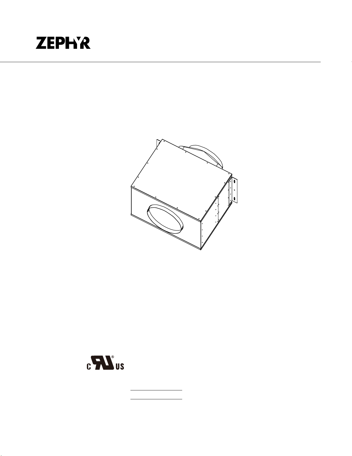
In-Line Blower
PBN-1000A
www.zephyronline.com
E12733 4
Model number:
Serial Number:
Use, Care, and Installation Guide
SEP14.0201 © Zephyr Ventilation LLC.
Page 2

www.zephyronline.com
Page 3

SAFETY NOTICE ................................................................. 2
LIST OF MATERIALS ....................................................... 3
INSTALLATION
Ductwork Calculation Sheet
Blower Positions
Specications
Mounting the Blower
.......................................................... 5
............................................................... 6
.................................................. 7
................................... 4
Table of Contents
1
Page 4

READ AND SAVE THESE INSTRUCTIONS
WARNING
TO REDUCE THE RISK OF FIRE, ELECTRIC SHOCK, OR INJURY TO PERSONS, OBSERVE THE FOLLOWING:
1. Use this unit only in the manner intended by the manufacturer.
If you have questions, contact the manufacturer at the address
or telephone number listed in the warranty.
2. Before servicing or cleaning unit, switch power off at service
panel and lock the service disconnecting means to prevent power
from being switched on accidentally. When the service disconnecting means cannot be locked, securely fasten a prominent
warning device, such as a tag, to the service panel.
3. Installation work and electrical wiring must be done by a qualified person(s) in accordance with all applicable codes and standards, including fire-rated construction codes and standards.
4. Sufficient air is needed for proper combustion and exhausting
of gases through the flue (chimney) of fuel burning equipment
to prevent backdrafting. Follow the heating equipment
manufacturer’s guideline and safety standards such as those
published by the National Fire Protection Association (NFPA),
and the American Society for Heating, Refrigeration and Air Conditioning Engineers (ASHRAE), and the local code authorities.
5. When cutting or drilling
into wall or ceiling, do not damage elec-
trical wiring and other hidden utilities.
6. Ducted fans must always be vented to the outdoors.
7. To reduce the risk of fire, use only metal ductwork.
8. If this unit is to be installed over a tub or shower, it must be
marked as appropriate for the application and be connected to
a GFCI (Ground Fault Interrupter) - protected branch circuit.
9. Never place a switch where it can be reached from a tub or
shower.
10. This unit must be grounded.
TO REDUCE THE RISK OF A RANGE TOP GREASE FIRE:
A. Never leave surface units unattended at high settings. Boilovers
cause smoking and greasy spillovers that may ignite. Heat oils
slowly on low or medium settings.
B. Always turn hood ON when cooking at high heat or when
flambeing food (i.e. Crepes Suzette, Cherries Jubilee, Peppercorn Beef Flambe’).
C. Clean ventilating fans frequently. Grease should not be allowed
to accumulate on fan or filter.
D. Use proper pan size. Always use cookware appropriate for the
size of the surface element.
TO REDUCE THE RISK OF INJURY TO PERSONS IN THE EVEN
T
OF A RANGE TOP GREASE FIRE, OBSERVE THE FOLLOWING:*
1. SMOTHER FLAMES with a close-fitting lid, cookie sheet, or metal
tray, then turn off the burner. BE CAREFUL TO PREVENT
BURNS. If the flames do not go out immediately, EVACUATE
AND CALL THE FIRE DEPARTMENT.
2. NEVER PICK UP A FLAMING PAN - You may be burned.
3. DO NOT USE WATER, including wet dishcloths or towels - vio-
lent steam explosion will result.
Installer: Leave this manual with
the homeowner.
!
FOR DOMESTIC COOKING ONLY
!
WARNING
4. Use an extinguisher ONLY if:
A. You know you have a Class ABC extinguisher and you already
know how to operate it.
B. The fire is small and contained in the area where it started.
C. The fire department is being called.
D. You can fight the fire with your back to an exit.
* Based on “Kitchen Fire Safety Tips” published by NFPA.
CAUTION
!
1. For general ventilating use only. Do not use to exhaust hazard-
ous or explosive materials and vapors.
2. To avoid motor bearing damage and noisy and/or unbalanced
impellers, keep drywall spray, construction dust, etc. off power
unit.
3. If ventilator is installed in an unconditioned space (such as
an attic): Surround the ventilator with thermal insulation - to
minimize possible condensation.
4. Please read specification label on product for further informa-
tion and requirements.
PBN-1000A Max. Watts - 640, Max. Amps - 5.45
www.zephyronline.com
Important Safety Notice
2
Page 5

AVERTISSEMENT
POUR RÉDUIRE LES RISQUES D’INCENDIE, DE DÉCHARGE
ÉLECTRIQUE OU DE BLESSURE, RESPECTEZ CES CONSIGNES :
1.
N’utilisez cet appareil que de la manière prévue par le fabricant.
Si vous avez des questions, communiquez avec le fabricant.
2.
Avant de procéder au nettoyage ou à l’entretien de l’appareil,
éteignez l’alimentation du panneau électrique et bloquez le dispositif
dedéconnexion pour éviter que l’alimentation électrique ne soit
accidentellement rallumée. Si le dispositif de sectionnement
d’électricité ne peut être bloqué, attachez un avertissement (comme
une étiquette) bien en vue sur le tableau électrique.
3.
Les travaux d’installation et de cablage electrique doivent etre faits
par une personne qualifiee selon les stipulations de tous les
normes et
standards en vigueur, dont les normes des constructions
ayant une cote de résistance au feu.
4.
Pour prévenir les contre-explosions, une certaine quantité d’air est
nécessaire pour la combustion et l’évacuation des gaz par le carneau
(cheminée) de l’appareil de combustion. Respectez les directives du
fabricant d’outillage de chauffage et les normes de sécurité comme
celles publiées par la NFPA (Association nationale des services
d’incendie), par la Société américaine des ingénieurs en chauffage,
réfrigération et climatisation (ASHRAE) et par les normes des
autorités locales.
5.
Lorsque vous coupez ou percez un mur ou un plafond, assurez-vous
de ne pas endommager le câblage électrique ou toute autre
installation technique dissimulée.
6.
Les ventilateurs canalisés doivent toujours évacuer l’air à l’extérieur.
7.
Pour reduire les risques d’incendie, n’utilisez que des conduits
d’aeration en metal.
9.
N’installez JAMAIS un interrupteur à une distance atteignable depuis
un bain ou une douche.
10.
Cet appareil doit etre mis a la terre
POUR RÉDUIRE LES RISQUES DE FEU DE GRAISSE SUR LA
SURFACE DE CUISSON :
A.
Ne laissez jamais l’appareil sans surveillance lors de son utilisation
à haute température. Les débordements par bouillonnement causent
de la fumée et des déversements de graisse qui peuvent prendre feu.
Faites chauffer l’huile à des températures basses ou moyennes.
B.
Allumez toujours la hotte lorsque vous cuisinez a houte
temperature ou que vous faites flamber des aliments.
C.
Nettoyez frequemment les ventilateurs de la hotte. La graisse ne
devrait jamais s’accumuler dans les ventilateurs ou les filtres.
D.
Utilisez des poêlons aux dimensions adéquates. Utilisez toujours une
batterie de cuisine correspondant aux dimensions de l’élément.
POUR RÉDUIRE LES RISQUES DE BLESSURE LORS D’UN
INCENDIE SUR LA SURFACE DE CUISSON :
1.
ÉTOUFFEZ LES FLAMMES avec un couvercle, une plaque à
biscuits ou un plateau de métal et éteignez ensuite le brûleur.
PRENEZ GARDE AUX RISQUES DE BRULURE. Si les flammes ne
disparaissent pas, EVACUEZ LES LIEUX ET APPELEZ LE
SERVICE D’INCENDIE.
2.
NE PRENEZ JAMAIS UN POÊLON EN FEU – Vous pourriez vous
brûler.
3.
N’UTILISEZ PAS D’EAU, ou un linge à vaisselle mouillé – une
violente explosion de vapeur s’ensuivra.
Installateur: Laisser ce manuel
au propretaire.
!
POUR LA CUISSON DOMESTIQUE
!
AVERTISSEMENT
4.
Utilisez un extincteur SEULEMENT si :
A.
Vous savez que vous possédez un extincteur de classe ABC et vous
savez vous en servir.
B.
Le feu est faible et ne s’est pas répandu depuis son point d’origine.
C.
Vous avez appelé le service d’incendie.
D.
Vous pouvez sortir facilement de l’endroit ou vous combattez le feu.
ATTENTION
!
1.
Pour ventilation générale seulement. N’utilisez pas cet appareil pour
évacuer des vapeurs et des matériaux explosifs ou dangereux.
2.
Pour eviter des dommages aux roulements moteur et les roues
asymetriques bruyants, garder cloison seche, poussiere de
construction, unite motrice.
3.
Si le ventilateur est installe dans un espace non (comme un
grenier) Entrourer le ventilateur avec isolation thermique pour
reduire au minimum la condensation eventuelle.
4.
S’il vous plait de lire l’etiquette du produit pour plus d’informations
et exigences.
PBN-1000A Max. Watts - 550, Max. Amps - 5A
3
Mise en garde de securite
Page 6

www.zephyronline.com
MODEL:
PARTS SUPPLIED
PBN-1000A
List of Materials
1 - In-Line blower
2 - Mounting brackets
1 - 10” to 8” transition
1 - Hardware package
HARDWARE PACKAGE CONTENTS
(4) M4 x 1-1/2”
PARTS NOT SUPPLIED
- Ducting, conduit, wiring and all installation tools
- Cable connector (if required by local codes)
- Range hood
(8) M4 x 8
4
Page 7

Duct pieces
3-1/ 4” x 10”
Rect.,
straight
Equivalent number
length x used =
1Ft. x( )=
To tal
Ft.
Duct pieces
6” Round
wall cap
withdamper
Equivalent number
length x used =
30 Ft. x( )=
To tal
Ft.
6” Round,
straight
7”-10” Round,
straight
3-1/ 4” x 10”
0
Rect.90
elbow
3-1/ 4” x 10”
0
Rect.45
elbow
3-1/ 4” x 10”
0
Rect.90
flat elbow
3-1/ 4” x 10”
Rect.
wallcap
with damper
3-1/ 4” x 10”
Rect.to
6” round
transition
3-1/ 4” x 10”
Rect.to
6” round
transition
0
elbow
90
6” Round,
0
90
elbow
1Ft. x( )=
1Ft. x( )=
15 Ft. x( )=
9Ft. x( )=
24 Ft. x( )=
30 Ft. x( )=
5Ft. x( )=
20 Ft. x( )=
15 Ft. x( )=
Ft.
Ft.
Ft.
Ft.
Ft.
Ft.
Ft.
Ft.
Ft.
6” Round,
roof cap
6” round to
3-1/ 4” x 10”
rect.
transition
6” round to
3-1/ 4” x 10”
rect.
transition
0
elbow
90
7” - 10”
Round,
0
elbow
90
7” - 10”
Round,
0
elbow
45
7” - 10”
Round
wall cap
withdamper
7” - 10”
Round,
roof cap
7” round to
31/4” x 10”
rect.
transition
7” round to
3-1/ 4” x 10”
rect.
transition
0
elbow
90
30 Ft. x( )=
1Ft. x( )=
16 Ft. x( )=
15 Ft. x( )=
9Ft. x( )=
30 Ft. x( )=
30 Ft. x( )=
8Ft. x( )=
23 Ft. x( )=
Ft.
Ft.
Ft.
Ft.
Ft.
Ft.
Ft.
Ft.
Installation – Ductwork Calculation Sheet
Ft.
6” Round,
0
elbow
45
9Ft. x( )=
Subtotal column1=
Maximum Duct Length: For satisfactory
air movement, the total duct length should
not exceed 100 equivalent feet.
Ft.
Ft.
Subtotal column2=
Subtotal column1=
Total ductwork =
Ft.
Ft.
Ft.
5
Page 8

www.zephyronline.com
outlet
4
5
2
outlet
outlet
outlet
1
Installation – Blower Positions
WARNING:
Check installation position so that the blower outlet is exhausting air away from the hood and
out of the home.
1. Mount on top of ceiling joists with plywood
2. Vertical mount to cross-members tied to trusses
3. Horizontal mount to cross-members tied to trusses
4. Mount on underside of rafters with wood blocking
5. Mount to cross-members tied to trusses with 90 degree elbow
Note1: When applicable, additional plywood may be used to simplify installation.
Note2: For some models, such as Cheng and Arc Collection, it is necessary to convert
from 10” round to 8” round ducting. A 10” to 8” transition is included with the
blower. Conversion must be done before ducting passes through ceiling.
Plywood
3
6
Page 9

1 9/16”
front side
(bracket positions)
outlet outlet
bracket
1 11/16”
5 1/2”
20 3/8”
top
(outlet)
9 15/16”
14 3/16”
15 7/8”
20 15/16”
10 3/8”
14 5/8”
7 5/16”
6 13/16”
3
7 5/16”
bottom
(inlet)
10 1/16”
21 7/8”
23 7/16”
8 5/8”
Installation – Specications
11 13/16”
7
Page 10

1. Determine blower position (examples on page 5).
2
bracket positions
outlet
d
due
!
accordance
properly grounded. Turn off electrical power at service entrance before wiring.
White (common)
Black (high)
Blue (med)
Red (low)
Green (ground)
PBN-1000A
HOOD
wiring harness
outlet
10” round
ducting
10” round
ducting
10” to 8”
transition
(if needed)
ceiling
wood
stud
PBN-1000A
in-line blower
bracket
electrical
conduit
8” round
ducting
Cable
Lock
Install each of the (2) mounting brackets to the sides of
the in-line blower housing using (4) M4x8 screws per
bracket. There are possible (4) mounting positions for
the brackets. FIG. A Note: Brackets must be secured
to studs using (2) M4 x 1-1/2” screws per bracket.
2. Run 10” round ducting to inlet and outlet of in-line blower
housing. Secure with aluminum duct tape. Note: Cheng
and Arc Collection hoods require a 10” to 8” round
transition to be installed prior to the duct passing through
the ceiling. 8” round ducting is then connected to the hood.
A 10” to 8” transition is included with the blower. FIG. B
3. Run electrical conduit per local codes from junction
box on top of in-line blower to blower wiring
harness on top of the range hood. See instructions
included with range hood for more information.
4. Run (5) wires through conduit (black, white, blue, red
and green ground). Check local code compliance
for style and gauge of wires. The ground wire shall
have a suitable gauge according to the Electrical Code
and Regulations. Connect wires to in-line blower and
blower wiring harness on hood per the diagram in FIG.
C. A cable lock (not supplied) might be required by local
codes. Check with local code requirements, purchase
and install appropriate connector if necessary. FIG. D
5. Turn circuit breaker on, power on hood and test all
Installation – Mounting the Blower
functions. Check for leaks around duct connections.
www.zephyronline.com
FIG. A
CAUTION: At least two installers are require
to the weight and size of the blower.
WARNING: Electrical wiring must be done by a qualified person(s) in
!
with all applicable codes and standards. This range hood must be
FIG. C FIG. D
8
FIG. B
 Loading...