

Page 1
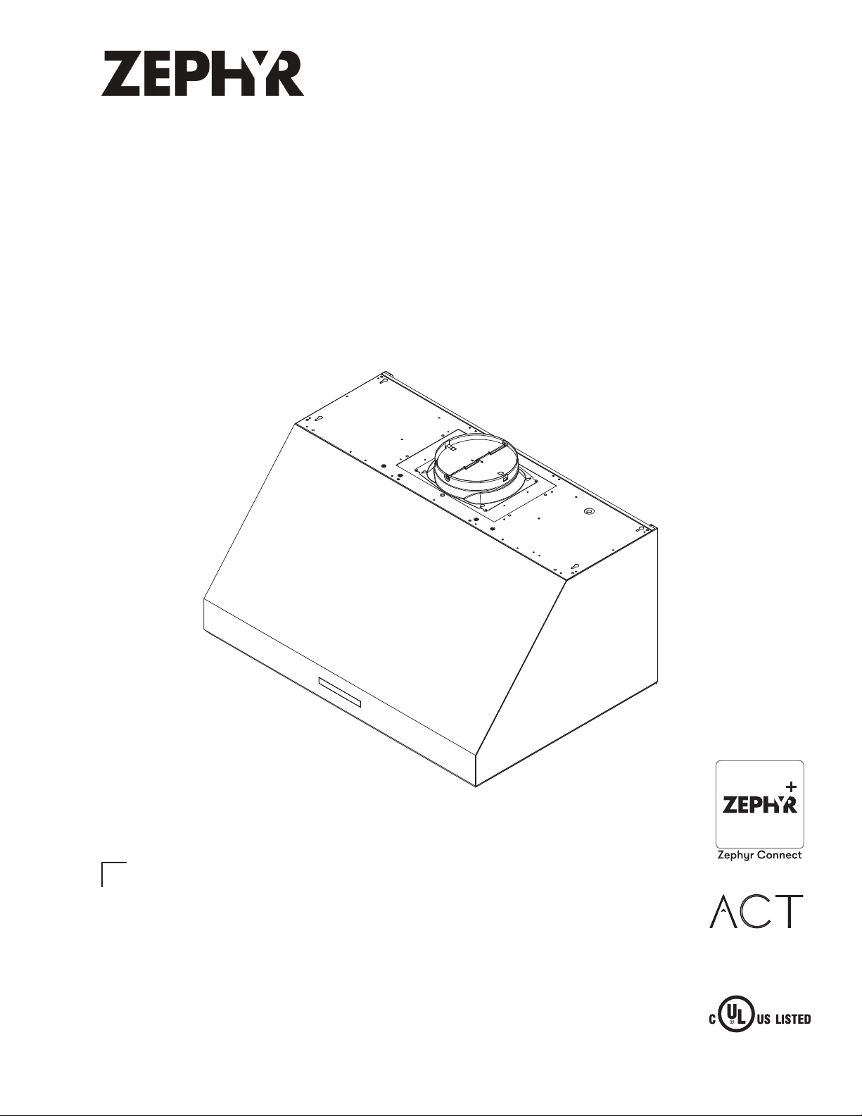
WWW.ZEPHYRONLINE.COM
Tidal II
AK7400AS, AK7436AS, AK7448AS
EN Use, Care, and Installation Guide
FR Guide d’utilisation, d’entretien et d’installation
NOV20.0101
C
Air flow Control Technology
TM
Page 2

PRO
TIDAL II
WALL
2
Tidal II Use, Care, and Installation Guide
Page 3

ZEPHYRONLINE.COM
Safety Information ............................................................................ 4-6
Types of Safety Warnings ................................................................... 4
General Safety ..................................................................................4-5
Operation ........................................................................................... 6
Electrical Requirements ...................................................................... 6
Federal Communication Commission Interface Statement ................. 6
List of Materials ................................................................................... 7
Installation Instructions .................................................................... 8-20
Ducting Calculation Sheet .................................................................. 8
Mounting Height, Clearance, & Ducting ...........................................9-10
Ducting Options ................................................................................. 11
Hood Specifications ............................................................................12
Electrical Supply .................................................................................13
Cable Lock .........................................................................................13
Horizontal Ducting Conversion ........................................................ 14-16
PBD-1300B Dual Blower Installation ..................................................17-19
Mounting the Hood ............................................................................ 20
Features & Controls ..........................................................................21-27
Proximity Controls ...........................................................................21-23
Zephyr Connect ..............................................................................24-25
Optional RF Remote Control ............................................................26-27
Maintenance ................................................................................... 28-30
Hood & Filter Cleaning .....................................................................28-29
LumiLight LED ................................................................................... 30
ACT™ Conversion .............................................................................31-33
Airflow Control Technology (ACT™) ....................................................31
Enabling ACT™ ................................................................................32-33
Wiring Diagram ............................................................................... 34-35
Troubleshooting............................................................................... 36-38
List of Parts & Accessories .................................................................. 39
Notes ..................................................................................................40
Limited Warranty ............................................................................... 41
Product Registration ...........................................................................42
Contents
Page
Tidal II Use, Care, and Installation Guide
3
Page 4
PRO
Safety Information
READ AND SAVE THESE INSTRUCTIONS
Your safety and the safety of others are very important.
We have provided many important safety messages in this
manual for your appliance. Always read and obey all safety
messages.
This is the Safety Alert Symbol. This symbol alerts you to
potential hazards that can cause severe bodily injury or death.
All safety messages will follow the Safety Alert Symbol and either
the words “DANGER” “WARNING” or “CAUTION”
DANGER
Danger means that failure to heed this safety statement may
result in severe injury or death.
WARNING
TIDAL II
WALL
WARNING
WARNING - TO REDUCE THE RISK OF FIRE, ELECTRIC SHOCK,
OR INJURY TO PERSONS, OBSERVE THE FOLLOWING:
a) Use this unit only in the manner intended by the
manufacturer. If you have questions, contact the manufacturer.
b) Before servicing or cleaning unit, switch power o at service
panel and lock the service disconnecting means to prevent
power from being switched on accidentally. When the service
disconnecting means cannot be locked, securely fasten a
prominent warning device, such as a tag, to the service panel.
CAUTION
For General Ventilating Use Only. Do Not Use To Exhaust
Hazardous Or Explosive Materials And Vapors. Take care
when using cleaning agents or detergents. Suitable for use in
household cooking area.
Warning means that failure to heed this safety statement
may result in extensive product damage, serious personal
injury, or death.
CAUTION
Caution means that failure to heed this safety statement
may result in minor or moderate personal injury, property or
equipment damage.
General Safety
WARNING
To reduce the risk of fire or electric shock, do not use this fan
with any solid-state control device.
WARNING
WARNING - TO REDUCE THE RISK OF A RANGE TOP GREASE
FIRE:
a) Never leave surface units unattended at high settings.
Boilovers cause smoking and greasy spillovers that may ignite.
Heat oils slowly on low or medium settings.
b) Always turn hood ON when cooking at high heat or
when flambeing food. (i.e. Crepes Suzette, Cherries Jubilee,
Peppercorn Beef Flambe’).
c) Clean ventilating fans frequently. Grease should not be
allowed to accumulate on fan or filter.
d) Use proper pan size. Always use cookware appropriate for
the size of the surface element.
4
Tidal II Use, Care, and Installation Guide
Page 5
ZEPHYRONLINE.COM
Safety Information
READ AND SAVE THESE INSTRUCTIONS
WARNING
WARNING - TO REDUCE THE RISK OF INJURY TO PERSONS
IN THE EVENT OF A RANGE TOP GREASE FIRE, OBSERVE THE
FOLLOWING:
a) SMOTHER FLAMES with a close-fitting lid, cookie sheet, or
metal tray, then turn o the burner. BE CAREFUL TO PREVENT
BURNS. If the flames do not go out immediately, EVACUATE AND
CALL THE FIRE DEPARTMENT.
b) NEVER PICK UP A FLAMING PAN – You may be burned.
c) DO NOT USE WATER, including wet dishcloths or towels – a
violent steam explosion will result.
d) Use an extinguisher ONLY if:
1) You know you have a Class ABC extinguisher, and you
already know how to operate it.
2) The fire is small and contained in the area where it
started.
3) The fire department is being called.
4) You can fight the fire with your back to an exit
Based on “Kitchen Firesafety Tips” published by NFPA.
WARNING
WARNING - TO REDUCE THE RISK OF FIRE, ELECTRIC SHOCK,
OR INJURY TO PERSONS, OBSERVE THE FOLLOWING:
a) Installation work and electrical wiring must be done by
qualified person(s) in accordance with all applicable codes and
standards, including fire-rated construction.
b) Sucient air is needed for proper combustion and
exhausting of gases through the flue (chimney) of fuel burning
equipment to prevent back drafting. Follow the heating
equipment manufacturer’s guideline and safety standards such
as those published by the National Fire Protection Association
(NFPA), and the American Society for Heating, Refrigeration
and Air Conditioning Engineers (ASHRAE), and the local code
authorities.
c) When cutting or drilling into wall or ceiling, do not damage
electrical wiring and other hidden utilities.
d) Ducted fans must always be vented to the outdoors.
e) If this unit is to be installed over a tub or shower, it must be
marked as appropriate for the application and be connected
to a GFCI (Ground Fault Circuit Interrupter) - protected branch
circuit.
WARNING
WARNING
TO REDUCE THE RISK OF FIRE, USE ONLY METAL DUCTWORK.
CAUTION
To reduce risk of fire and to properly exhaust air outside, do
not vent exhaust air into spaces within walls, ceilings, attics,
crawl spaces, or garages.
WARNING
Prop. 65 Warning for California Residents: This product may
contain chemicals known to the State of California to cause
cancer, birth defects, or other reproductive harm.
Tidal II Use, Care, and Installation Guide
5
Page 6

PRO
Safety Information
TIDAL II
READ AND SAVE THESE INSTRUCTIONS
Operation
Ź Always leave safety grilles and filters in place. Without these components, operating blowers could catch onto hair, fingers and
loose clothing.
Ź The manufacturer declines all responsibility in the event of failure to observe the instructions given here for installation,
maintenance and suitable use of the product. The manufacturer further declines all responsibility for injury due to negligence and
the warranty of the unit automatically expires due to improper maintenance.
NOTE: Please check www.zephyronline.com for revisions before doing any custom work.
Electrical Requirements
Important:
Ź Observe all governing codes and ordinances.
Ź It is the customer’s responsibility to be aware of these below:
Ź To contact a qualified electrical installer.
Ź To assure that the electrical installation is adequate and in conformance with National Electrical Code, ANSI/NFPA 70 latest
edition* or CSA standards C22.1-94, Canadian Electrical Code, Part 1 and C22.2 No.0-M91 - latest edition** and all local codes
and ordinances.
Ź If codes permit and a separate ground wire is used, it is recommended that a qualified electrician determine that the ground path
is adequate.
Ź Do not ground to a gas pipe.
Ź Check with a qualified electrician if you are not sure the range hood is properly grounded.
Ź Do not have a fuse in the neutral or ground circuit.
Ź This appliance requires a 120V 60Hz electrical supply and connected to an individual properly grounded branch circuit protected
by a 15 or 20 ampere circuit breaker or time delay fuse. Wiring must be 2 wire with ground. Please also refer to Electrical Diagram
on product.
Ź A cable locking connector (not supplied) might also be required by local codes. Check with local requirements, purchase and
install appropriate connector if necessary.
* National Fire Protection Association Batterymarch Park, Quincy, Massachusetts 02269
** CSA International 8501 East Pleasant Valley Road, Cleveland, Ohio 44131-5575
WALL
Federal Communication Commission Interface Statement
Ź This equipment has been tested and found to comply with the limits for a Class B digital device, pursuant to Part 15 of the FCC
Rules. These limits are designed to provide reasonable protection against harmful interference in a residential installation.
Ź This equipment generates, uses and can radiate radio frequency energy and, if not installed and used in accordance with the
instructions, may cause harmful interference to radio communications. However, there is no guarantee that interference will not
occur in a particular installation. If this equipment does cause harmful interference to radio or television reception, which can be
determined by turning the equipment o and on, the user is encouraged to try to correct the interference by one of the following
measures:
Ź Reorient or relocate the receiving antenna.
Ź Increase the separation between the equipment and receiver.
Ź Connect the equipment into an outlet on a circuit dierent from that to which the receiver is connected.
Ź Consult the dealer or an experienced radio/TV technician for help.
6
Tidal II Use, Care, and Installation Guide
Page 7
ZEPHYRONLINE.COM
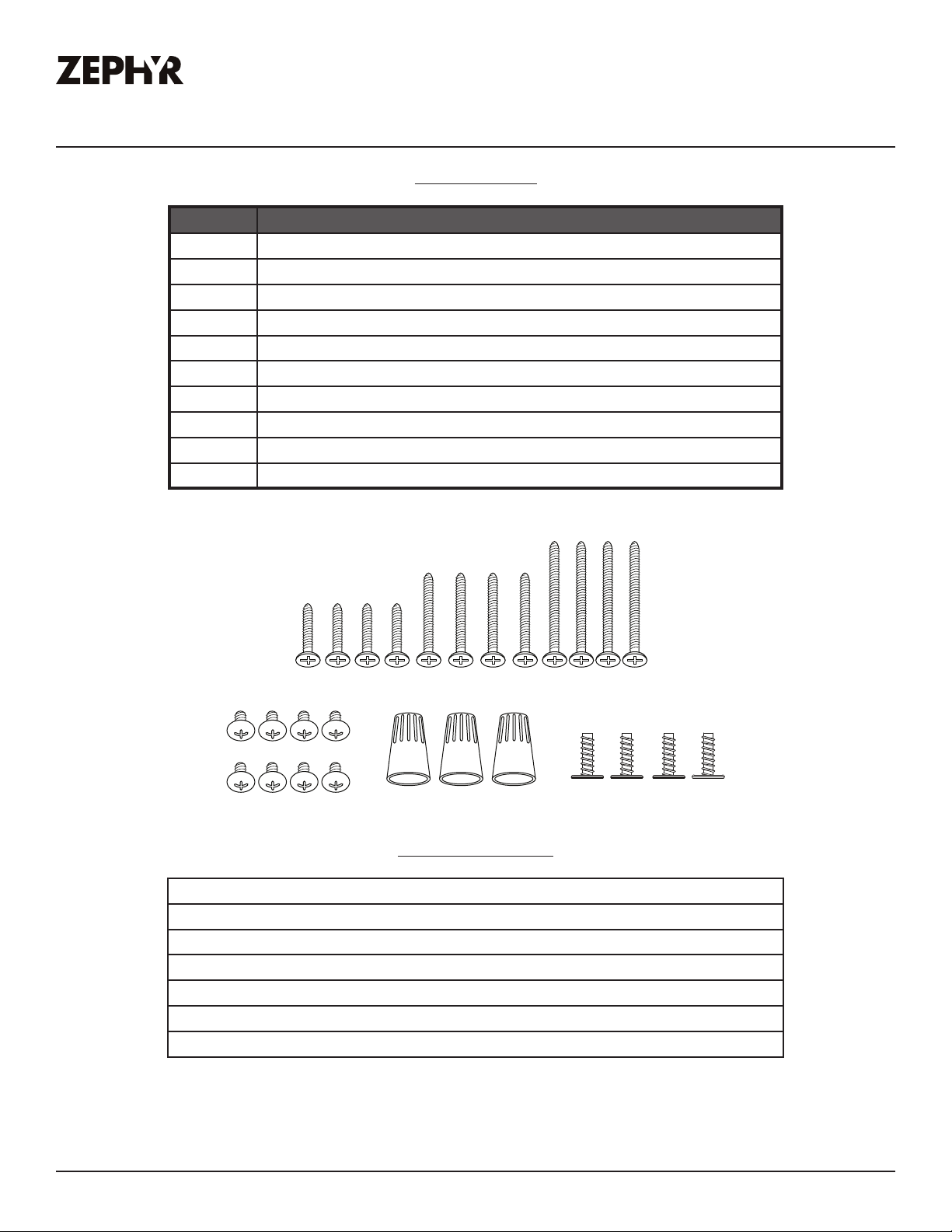
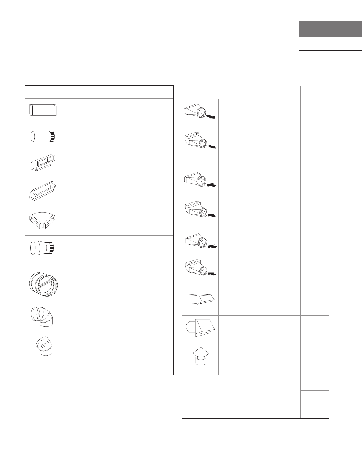
List of Materials
Parts Supplied
Quantity Part
1Hood
2 Pro bae filters (AK7400AS, AK7436AS)
3 Pro bae filters (AK7448AS)
2 LumiLight LED, 6W (pre-installed) (AK7400AS, AK7436AS)
4 LumiLight LED, 6W (pre-installed) (AK7448AS)
1 8” round backdraft damper (pre-installed)
1 3-1/4” x 10” rectangular collar with damper
1 Single blower motor (pre-installed)
1 Top cover plate (for horizontal ducting)
1 Hardware package
#6 x 2” (4 )
#6 x 1-1/2” (4 )
#6 x 1” (4 )
M3.5 x 8 (8)
Ducting, conduit and all installation tools
Cable locking connector (if required by local codes)
Duct cover extension kit
Recirculating kit
RF remote control
Dual blower motor
Wood board to hang hood (WxDxH)
Wire Caps (3)
Parts Not Supplied
3/16 x 3/8 (4)
AK7400AS: 27” x 1/2” x 4”
AK7436AS: 33” x 1/2” x 4”
AK7448AS : 45” x 1/2” x 4”
Tidal II Use, Care, and Installation Guide
7
Page 8
PRO
Installation Instructions
Ducting Calculation Sheet
Duct pieces
3- 1/ 4” x 10”
Rect.,
straight
6”, 7”, 8”, 10”
Round,
straight
3- 1/ 4” x 10”
Rect. 90
elbow
3- 1/ 4” x 10”
Rect. 45
elbow
3- 1/ 4” x 10”
Rect. 90
flat elbow
7” to 6” or
8” to 7” Round
tapered
reducer
6”, 7“, 8”
Round
in-line
damper
6”, 7”, 8”, 10”
Round,
0
90
elbow
6”, 7”, 8”, 10”
Round,
0
45
elbow
Equivalent number
length x used =
1 Ft. x ( ) =
1 Ft. x ( ) =
15 Ft. x ( ) =
0
9 Ft. x ( ) =
0
24 Ft. x ( ) =
0
25 Ft. x ( ) =
15
Ft. x ( ) =
15 Ft.
9 Ft. x ( ) =
Subtotal column 1 =
x ( ) =
To t a l
Ft.
Ft.
Ft.
Ft.
Ft.
Ft.
Ft.
Ft.
Ft.
Ft.
Duct pieces
3- 1/ 4” x 10”
Rect. to
6” round
transition
3- 1/ 4” x 10”
Rect. to
6” round
transition
0
elbow
90
6” round to
3- 1/ 4” x 10”
rect.
transition
6” round to
3- 1/ 4” x 10”
rect.
transition
0
90
elbow
7” round to
3 1/ 4” x 10”
rect.
transition
7” round to
3- 1/ 4” x 10”
rect.
transition
0
elbow
90
3- 1/ 4” x 10”
Rect.
wall cap
with damper
6”, 7”, 8”, 10”
Round, wall
cap with
damper
6”, 7”, 8”, 10”
Round
roof cap
Equivalent number
length x used =
5 Ft. x ( ) =
20 Ft. x ( ) =
1 Ft. x ( ) =
16 Ft. x ( ) =
8 Ft. x ( ) =
23 Ft. x ( ) =
30 Ft. x ( ) =
30 Ft. x ( ) =
30 Ft. x ( ) =
To t a l
TIDAL II
WALL
Ft.
Ft.
Ft.
Ft.
Ft.
Ft.
Ft.
Ft.
Ft.
8
Maximum Duct Length: For satisfactory air movement,
the total duct length
should not exceed 150 equivalent feet.
Subtotal column 2 =
Subtotal column 1 =
Total ductwork =
Ft.
Ft.
Ft.
Tidal II Use, Care, and Installation Guide
Page 9
Installation Instructions
ZEPHYRONLINE.COM
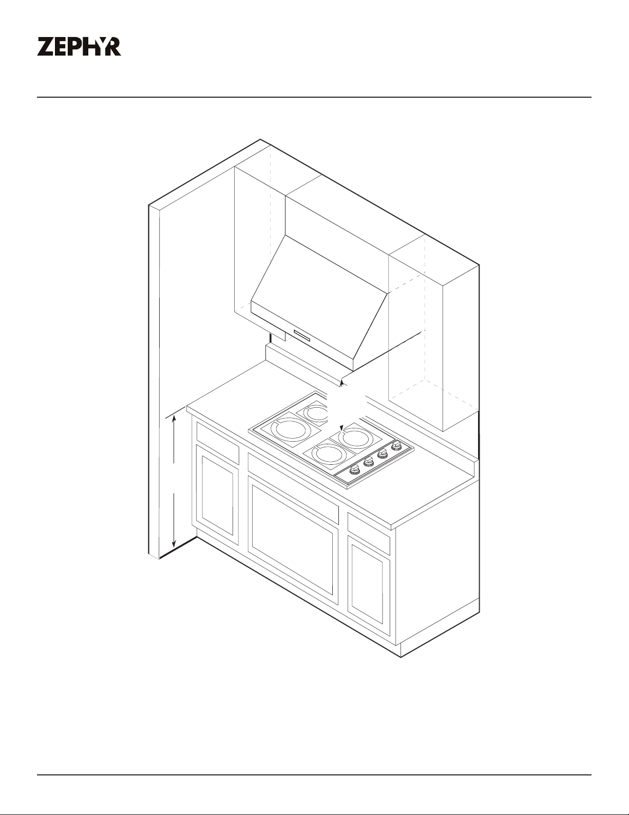
Mounting Height, Clearance, & Ducting
36”
24” min.
34” max.
Tidal II Use, Care, and Installation Guide
9
Page 10

PRO
Installation Instructions
TIDAL II
WALL
Mounting Height, Clearance, & Ducting
A minimum of 8” round duct or 3-1/4” x 10” rectangular duct is recommended to maintain maximum
air flow eciency for single blower and 10” round duct for dual internal blower for both vertical and
horizontal ducting.
Always use rigid type metal ducts only. Flexible ducts could restrict air flow by up to 50%.
Also use the ducting calculation sheet (on page 11) to compute total available duct run when using
elbows, transitions and caps.
ALWAYS, when possible, reduce the number or transitions and turns. If long duct run is required,
increase duct size from 8” to 10”.
If turns or transitions are required; install as far away from hood duct output and as far apart,
between the two as possible.
Minimum mount height between range top to hood bottom should be no less than 24”.
Maximum mount height should be no higher than 34”.
It is important to install the hood at the proper mounting height. Hoods mounted too low could result
in heat damage and fire hazard; while hoods mounted too high will be hard to reach and will lose its
performance and eciency.
If available, also refer range manufacturer’s height clearance requirements and recommended hood
mounting height above range. Always check your local codes for any dierences.
Duct cover extension kit available for ceiling heights up to 12 feet. Turn to the list of parts and
accessories section for part number and ordering information.
For shipment and installation damages:
Ź Please fully inspect unit for damage before installation.
Ź If the unit is damaged in shipment, return the unit to the store in which it was bought for repair or
replacement.
Ź If the unit is damaged by the customer, repair or replacement is the responsibility of the customer.
Ź If the unit is damaged by the installer (if other than the customer), repair of replacement must be
made by arrangement between customer and installer.
10
Tidal II Use, Care, and Installation Guide
Page 11
Installation Instructions
ZEPHYRONLINE.COM
Ducting Options
WARNING
Fire Hazard: NEVER exhaust air or terminate ductwork into
spaces between walls, crawl spaces, ceilings, attics, or garages.
All exhaust must be ducted to the outside, unless using the
recirculating option.
Ź Use single wall rigid metal ductwork only.
Ź Fasten all connections with sheet metal screws and tape all joints w/ certified Silver Tape or Duct
Tape.
ductless
recirculating
Roof Pitch w/
Flashing & Cap
Sot or crawl space
Rear Ducting
Side wall cap
w/ gravity damper
Tidal II Use, Care, and Installation Guide
11
Page 12
PRO
Installation Instructions
Ů
Top
27-7/8” (30“)
33-7/8” (36”)
1”
1-1/8”
8-9/16”
45-13/16” (48”)
6”
11-9/16”
2-5/8”
*7-7/8”
**10-3/8”
TIDAL II
WALL
Side
12”
18”
12-9/16”
4”
3-3/8” (30“)
6-3/8” (36”)
12-3/8” (48”)
1-11/16”
*9-1/2”
**14-3/16”
29-15/16” (30“)
35-7/8” (36”)
47-7/8” (48”)
Back
*7-3/4”
**9-15/16”
*7-7/8”
**10-3/8”
***3-3/16”
3-1/4”
1-11/16”
16-1/8”
* 8” round ducting
** 10” round ducting
*** Rectangular ducting
13-9/16”
24”
Back
5-1/4”
18”
12
*9-1/2”
**14-3/16”
***9-7/8”
21-1/4”
27-3/8” (30“, 36”)
35-1/4” (48”)
Tidal II Use, Care, and Installation Guide
Page 13
Installation Instructions
ZEPHYRONLINE.COM
Electrical Supply
WARNING
Electrical wiring must be done by qualified person(s) in
accordance with all applicable codes and standards. Turn o
electrical power at service entrance before wiring.
For personal safety, remove house fuse or open circuit breaker before beginning installation. Do not
use extension cord or adapter plug with this appliance.
Follow national electrical codes or prevailing local codes and ordinances.
This appliance requires a 120V 60Hz electrical supply, and connected to an individual, properly
grounded branch circuit, protected by a 15 or 20 ampere circuit breaker or time delay fuse. Wiring
must be 2 wire w/ ground. Please also refer to the Electrical Diagram labeled on product.
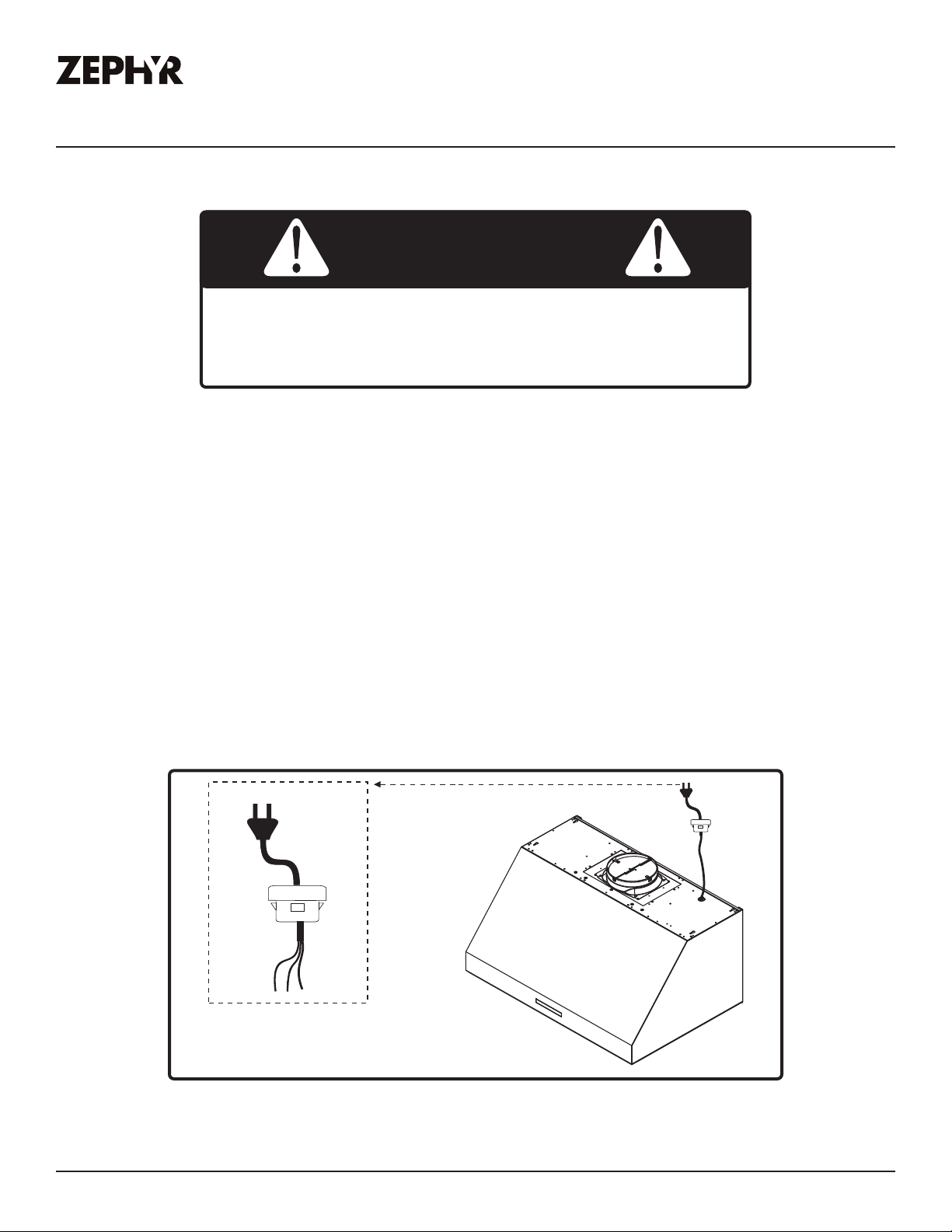
Cable Lock
A cable locking connector (not supplied) might be required by local codes. Check with local
requirements and codes, purchase and install appropriate connector if necessary. (FIG. A)
Cable Lock
FIG. A
Tidal II Use, Care, and Installation Guide
13
Page 14
PRO
Installation Instructions
TIDAL II
WALL
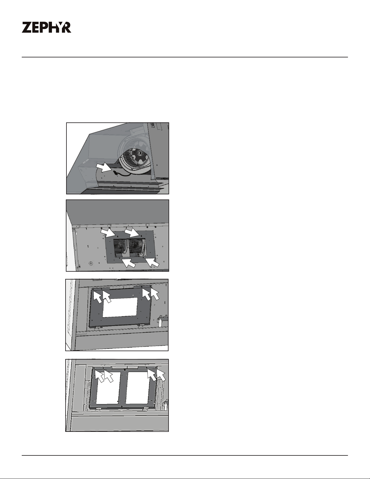
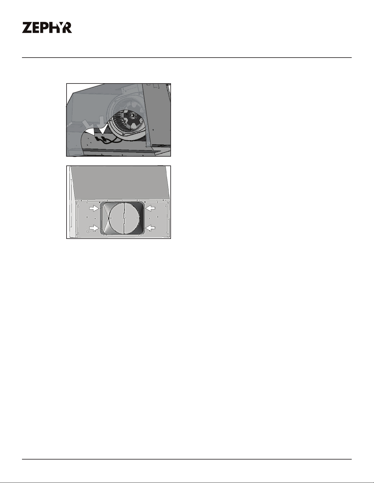
Horizontal Ducting Conversion
By default the Tidal II is pre-configured for 8” round vertical ducting. These steps are for 8” round
and 3-1/4”x10” rectangular horizontal ducting. If you are continuing with vertical ducting, please skip
these steps.
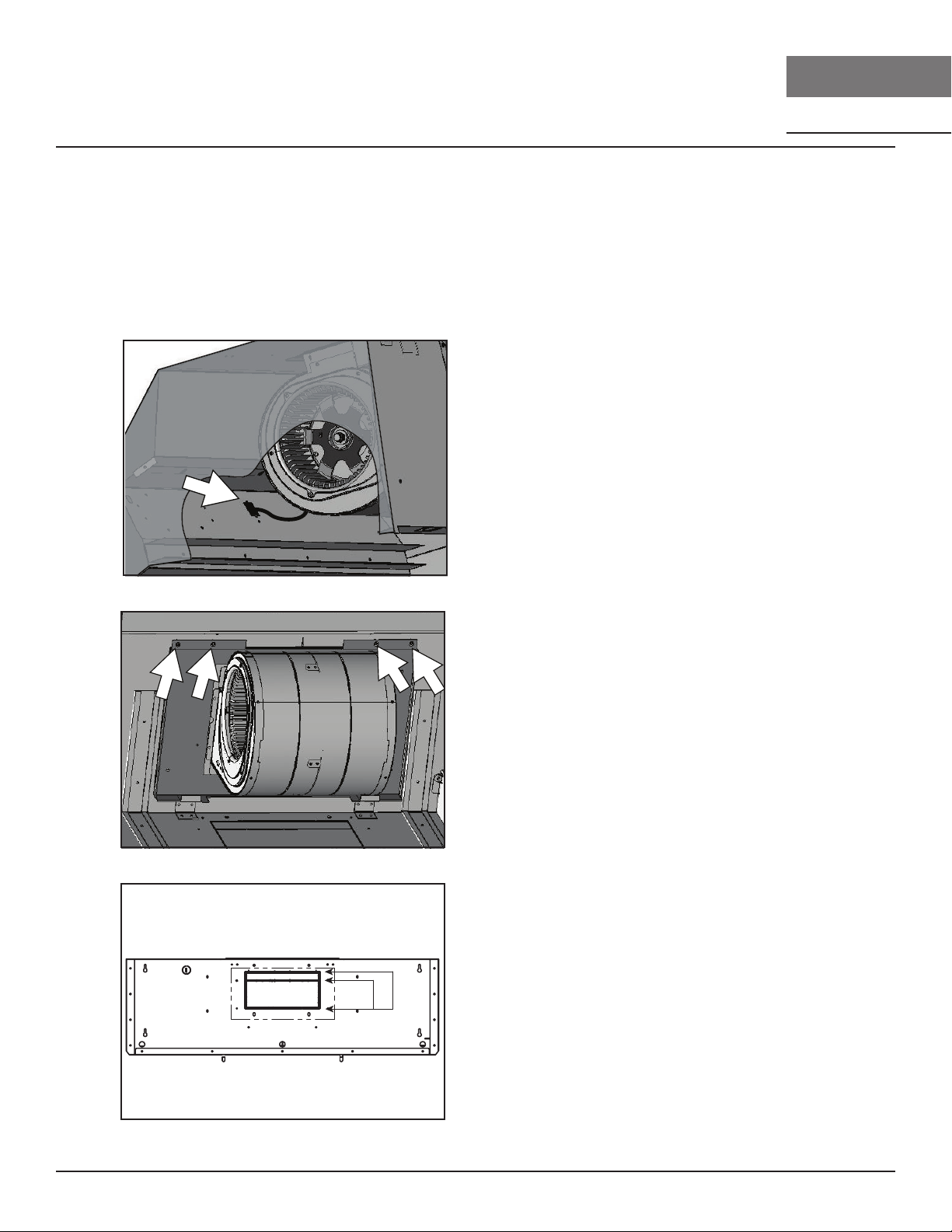
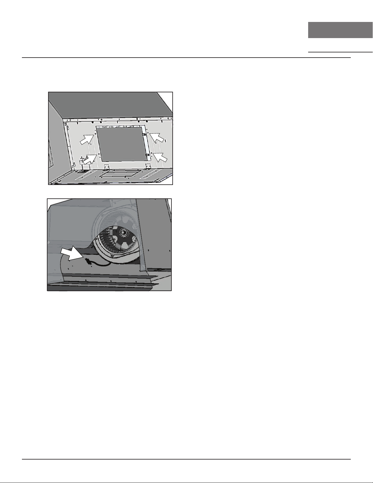
1. Disconnect blower plug.
2. Remove (4) screws from interior
of hood body attaching single
blower plate to top of hood body.
Remove single blower and single
blower plate.
3. Using a flat-head screwdriver,
remove the smaller rectangular
knock-out plate (A) for 3-1/4” x
B
A
10” rectangular ducting or the
larger knock-out plate (B) for 8”
round ducting located on the
back of hood.
14
Tidal II Use, Care, and Installation Guide
Page 15
ZEPHYRONLINE.COM
Horizontal Ducting Conversion
Installation Instructions
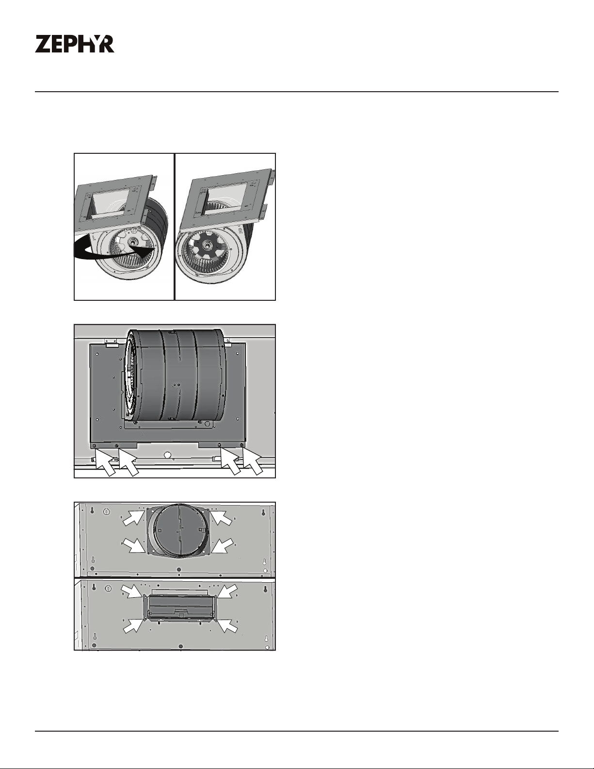
4. Remove (4) screws attaching
blower to blower plate. Turn
blower 180 degrees and reattach
to blower plate.
5. Position single blower with single
blower plate as shown. Be sure to
tuck back of single blower plate
into tabs at back of hood. Secure
single blower plate to back of
hood using (4) screws removed
from step 2.
6. Attach 8” round duct collar or
3-1/4” x 10” rectangular duct
collar to back of hood body using
(4) M3.5 x 8 screws.
Tidal II Use, Care, and Installation Guide
15
Page 16
PRO
Installation Instructions
Horizontal Ducting Conversion
TIDAL II
WALL
7. From inside hood body, position
top cover plate to top of hood
body. From outside hood body,
attach top cover plate to top of
hood body using (4) 3/16 x 3/8
screws.
8. Connect blower plug.
16
Tidal II Use, Care, and Installation Guide
Page 17
Installation Instructions
ZEPHYRONLINE.COM
PBD-1300B Dual Blower Installation
This range hood is equipped standard with a single blower vertical duct option. To convert from
single blower vertical ducting to dual blower vertical ducting please following the instructions below.
PBD-1300B dual blower kit is compatible with all Tidal II sizes.
1. Remove the bae filters and
if applicable, remove the side
panels. Disconnect blower plug.
2. Remove (4) screws at top of
hood body attaching blower to
blower plate. Remove blower from
interior of hood body.
3. Remove (4) screws from interior
of hood body attaching blower
plate to hood body. Remove
blower plate.
4. Install dual blower plate from
PBD-1300B kit into hood body.
Attach by (4) screws previously
removed from step 3.
Tidal II Use, Care, and Installation Guide
17
Page 18
PRO
Installation Instructions
PBD-1300B Dual Blower Installation
5. Install previously removed blower
6. Install blower from PBD-1300B
TIDAL II
WALL
onto one side of dual blower plate
and attach by (4) previously
removed screws from step 2.
kit onto other side of dual blower
plate by (4) 3/16 x 3/8 screws.
7. Dual blower screw mount
locations.
8. Remove (4) screws to remove the
light panel. Install dual blower
PCB inside the hood body.
18
Tidal II Use, Care, and Installation Guide
Page 19
Installation Instructions
ZEPHYRONLINE.COM
PBD-1300B Dual Blower Installation
9. Refer to page 32-33 section for
10. Place 10” round adapter
this step. Connect the wiring
from the dual blower including
both blower plugs, blower cable
6 pin connector (E), dual blower
switch cable (H), black single pin
power cord from dual blower (K),
and white single pin power cord
(F) to dual blower PCB.
(included with PBD-1300B) on top
of hood and secure with (4) M3.5
x 8 screws.
NOTE: To secure the 10” transition adapter to top of hood a cut out of 14-1/2” width x 10-1/2” depth
will need to be made in the cabinet bottom.
If internal cabinet dimensions prevent this size of a cut out then the 10” transition adapter may be
mounted to the cabinet bottom rather than the top of the hood. Cut out dimensions for this type of
installation are 13-1/4” width x 6-1/4” depth.
Tidal II Use, Care, and Installation Guide
19
Page 20
PRO
C/L
C/L
A
B
16-7/8”
min
24”
4”
wood board
Installation Instructions
TIDAL II
WALL
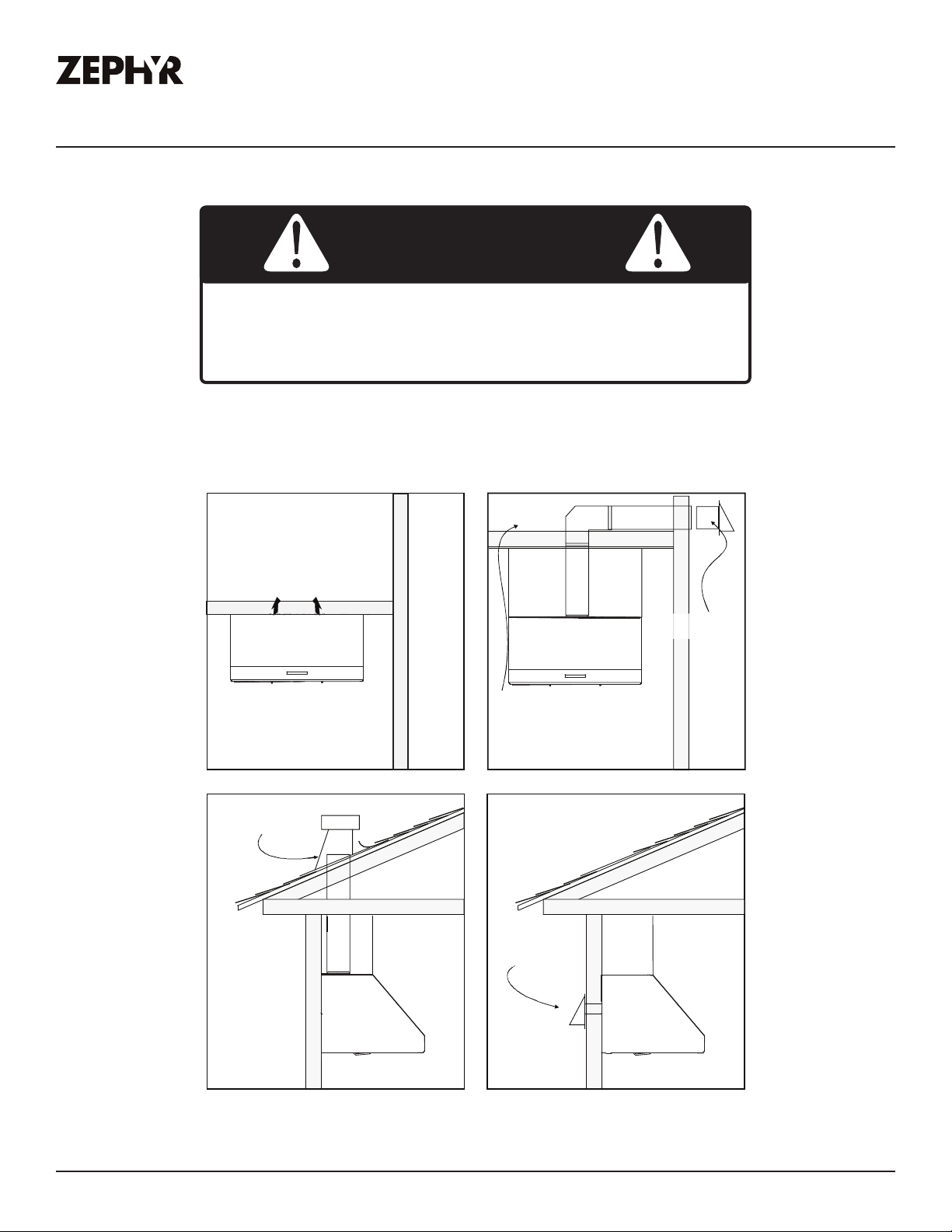
Mounting the Hood
If recirculating range hood refer to the manual included with ZRC-70xxC recirculating kit or on our
website prior to installing hood.
CAUTION
At least two installers are required due to the
weight and size of the hood.
1. Select preferred ducting application (vertical
or horizontal) and prepare hood. Remove the
safety screw on top of hood body.
2. Choose desired height above cooking surface
(24” min). Level and mark hood bottom, line A
(FIG. B)
3. Plum and mark center line on wall.
4. Level and mark top of wood board, line B (FIG.
B) 16-7/8” from line A.
5. Mark center line of wood board. Center and
align top of board with line B. Secure wood
board to studs using (4) #6 wood screws. Wood
Board Dimensions: (W x D x H)
30”: 27” x 1/2” x 4”
36”: 33” x 1/2” x 4”
48”: 45” x 1/2” x 4”
6. Prepare duct pipe and duct cut outs in upper cabinet if needed or wall if horizontally ducting
hood. Prepare electrical wiring and electrical cut outs in upper cabinet if needed or wall if
horizontal electrical hook up is required. Refer to hood specifications on page 15 for dimensions.
7. Mount hood onto wood board and secure using (4) #6 wood screws. Further secure hood onto wall
through lower body screw holes by (2) #6 wood screws.
8. Install electrical and duct work and seal with certified aluminum duct tape.
FIG. B
9. If using RF remote control, remove bae filters and remove the light panel by (4) screws and
extend the blue antenna wire. There is no need to secure it. Reinstall light panel and bae filters.
10. Power up hood and check for leaks around duct tape.
20
Tidal II Use, Care, and Installation Guide
Page 21
ZEPHYRONLINE.COM
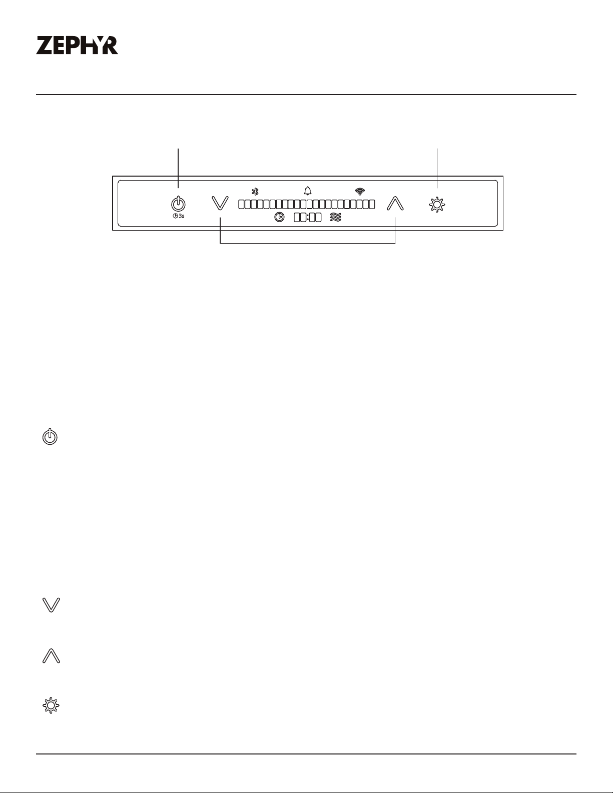
Proximity Controls
Power Lights
PROXIMITY SENSOR
Ź When approaching the hood while it is powered o, the Power, Fan Decrease, Fan Increase,
and Light icons will illuminate, and “HELLO” will appear on the LCD display for 2 seconds.
Features & Controls
Display & Icons
Adjust 6 Speed Levels
Ź If neither the fan nor lights are turned on within 60 seconds, the icons will turn o, and
“GOODBYE” will appear on the LCD display for 2 seconds.
Ź The icons will not disappear until the fan and lights are turned o.
CONTROL ICONS
Power
Ź Press the power icon to power on or o the fan and lights.
Ź The hood has a memory function to remember the last used settings for the fan and lights.
Ź After pressing the power icon to power o the hood, “GOODBYE” will appear on the LCD
display for 2 seconds.
Ź The 3s icon under the power icon only illuminates when the fan is powered on. It is an
indicator to enable Automatic Delay O by pressing and holding the power button
for 3 seconds.
Decrease Fan Speed
Ź Press the icon to decrease fan speed from 6, 5, 4, 3, 2, 1, o.
Increase Fan Speed
Ź Press the icon to increase fan speed from o, 1, 2, 3, 4, 5, 6.
Lights
Ź Press the lights icon to change lighting level from 1, 2, 3, o.
Tidal II Use, Care, and Installation Guide
21
Page 22

PRO
Features & Controls
Proximity Controls
DISPLAY ICONS & FUNCTIONS
Ů
Ź The notification bell icon will illuminate when an action needs to be taken. Tapping the
icon will cycle through the notifications. The notification bell will remain illuminated until all
notifications are resolved. The notification bell will not illuminate when the hood and controls
are powered o.
Bluetooth®
Ź The Bluetooth® icon will illuminate the device when connected with the hood via Bluetooth®.
The words “BLUETOOTH CONNECTED” or “BLUETOOTH DISCONNECT” will appear on the
LCD display whenever the connection changes.
Wi-Fi
TIDAL II
WALL
Ź The Wi-Fi icon will illuminate when the hood is connected to the Wi-Fi. The words “WIFI
CONNECTED” or “WIFI DISCONNECTED” will appear on the LCD display whenever the
connection changes which will be managed via the Zephyr Connect app.
Ű
Ź While the fan is on, press and hold for 3 seconds to enable the delay o timer. The fan will
change to speed 1, the timer display will illuminate, the LCD display will show “AUTOMATIC
DELAY OFF”, and the timer will begin counting down from 10 minutes. After the timer reaches
0, the fan and lights will power o.
Ź The automatic delay o function timer begins at 10 minutes by default. The Zephyr Connect
app provides the options for either 5 or 10 minutes.
CleanAir
Ź When the fan is o, press and hold and simultaneously for 3 seconds to enable or
disable the CleanAir function. The LCD display will show “CLEAN AIR ENABLED” or “CLEAN
AIR DISABLED”.
Ź When enabled, the fan will turn on speed 1 every 4 hours for 10 minutes. While the fan is
running, the LCD display will show “CLEAN AIR ACTIVE” and the CleanAir icon will illuminate.
22
Tidal II Use, Care, and Installation Guide
Page 23

ZEPHYRONLINE.COM
Proximity Controls
ĻŮ
Ź Airflow Control Technology (ACT™) allows the installer to set the maximum fan CFM to align
with local codes and regulations. When the fan is o, press and hold
display ACT™ status.
Ź ACT 290 = 3 speeds, ACT 390 = 4 speeds, ACT 590 = 5 speeds.
Grease Filter Clean Reminder
Ź After 60 hours of fan use, the notification bell icon will illuminate. When the bell is tapped,
the LCD display will cycle between showing “CLEAN GREASE FILTERS” and then “HOLD
DOWN TO RESET” every 2 seconds. If no action is taken for 30 seconds, the display turns o
and the notification bell icon will remain illuminated.
Ź To hold down and reset, press and hold the fan decrease button for 3 seconds to
reset. The Zephyr Connect app provides the option to reset the reminder.
Features & Controls
for 3 seconds to
Recirculating Mode - Charcoal Filter Replacement Reminder
Ź Hold and for 3 seconds to enable or disable recirculating mode which will remind you
to replace the charcoal filter. The LCD display will show “RECIRCULATING ENABLED” to
enable and “RECIRCULATING DISABLE” to disable for 2 seconds.
Ź After 200 hours of fan use, the notification bell icon will illuminate. When the bell is tapped,
the LCD display will cycle between showing “REPLACE CHARCOAL FLTR” and “HOLD UP TO
RESET” every 2 seconds. If no action is taken for 30 seconds, the display turns o and the
notification bell will remain illuminated.
Ź To hold up and reset, press and hold the fan increase button for 3 seconds to reset.
The Zephyr Connect app provides the option to reset the reminder.
Remote Control Pairing Mode
Ź Hold for 3 seconds to enable remote control pairing mode. Once pairing mode is enabled,
the LCD display will illuminate “REMOTE PAIRING”. Press a button on the remote control to
synchronize it with the hood.
Tidal II Use, Care, and Installation Guide
23
Page 24
PRO
Features & Controls
TIDAL II
WALL
Zephyr Connect
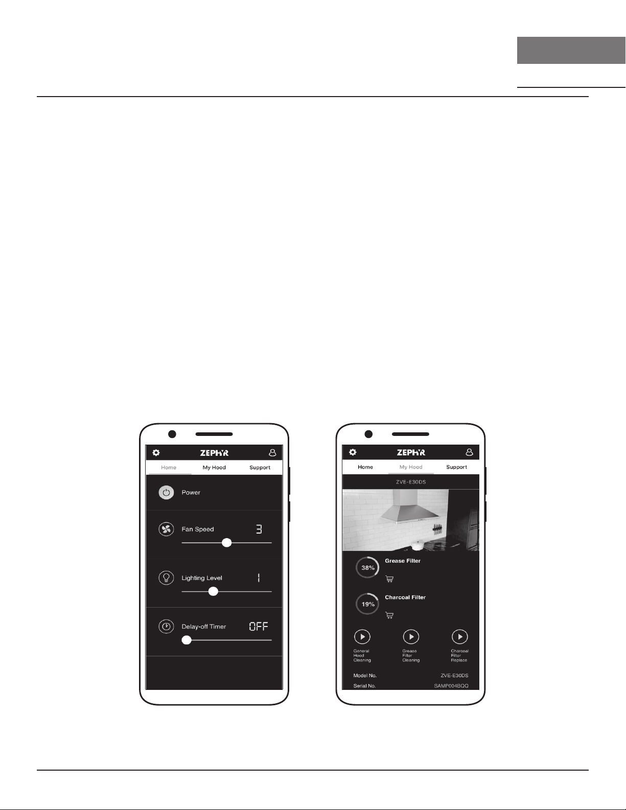
Your range hood is compatible with our Zephyr Connect app. All you need is a WiFi connection with
access to the Internet that can reach the location of your range hood. Zephyr Connect allows you to
control your range hood from anywhere using a mobile device or your Amazon Alexa or Google Home
smart speaker. Zephyr Connect also includes real time diagnostics and provides you with important
product information.
The Zephyr Connect app is available on iOS devices using iOS 11.0 or later or Android devices using
Android version 8 or later. Visit the Apple App Store or Google Play Store for more information.
If your range hood is not connected to WiFi, the functionality will operate similarly to a typical range
hood without WiFi connectivity.
Please review the included Zephyr Connect Quick Start Guide for more information.
If you have connected your hood with either Amazon Alexa or Google Home smart speakers, you now
have voice control capabilities. The list of commands for Amazon Alexa and Google Home are on the
next page.
NOTE: Amazon Alexa and Google Home cannot support the voice commands in French.
24
Tidal II Use, Care, and Installation Guide
Page 25
Features & Controls
ZEPHYRONLINE.COM
Zephyr Connect
Control Type Amazon Alexa Voice Commands Description
Power
Fan
Light
Delay-O
Alexa, turn on [Hood Name] Turn on range hood power
Alexa, turn o [Hood Name] Turn o range hood power
Alexa, increase [Hood Name] Fan Speed Increase fan speed on range hood
Alexa, decrease [Hood Name] Fan Speed Decrease fan speed on range hood
Alexa, set [Hood Name] Fan Speed to [1-6] Set range hood to specific fan speed
Alexa, set [Hood Name] Fan Speed to Maximum Set fan speed to 6 on range hood
Alexa, set [Hood Name] Fan Speed to Minimum Set fan speed to 1 on range hood
Alexa, turn on [Hood Name] Light Turn on the light on range hood
Alexa, turn o [Hood Name] Light Turn o the light on range hood
Alexa, increase [Hood Name] Light(s) Increase light level on range hood
Alexa, decrease [Hood Name] Light(s) Decrease light level on range hood
Alexa, set [Hood Name] Light(s) to High
Alexa, set [Hood Name] Light(s) to Bright
Alexa, set [Hood Name] Light(s) to Low
Alexa, set [Hood Name] Light(s) to Dim
Alexa, set [Hood Name] Light(s) to [1-3] Set range hood to specific light level
Alexa, set delay time to 1 minute on [Hood Name]
Alexa, set delay time to 2-10 minutes on [Hood Name]
Alexa, [Start/Enable] [Hood Name] Delay O Timer Enable delay o timer for 10 minutes. After 10
Alexa, [Stop/Disable] [Hood Name] Delay O Timer Disable delay o timer
Set light level to High on range hood
Set light level to Low on range hood
Enable delay timer for 1-10 minutes. After 1-10
minutes, the hood will be power o.
minutes, the hood will power o.
Control Type Google Home Voice Command Description
Power
Fan
Light
Delay-O
Hey Google, turn on [Hood Name] Turn on range hood power
Hey Google, turn o [Hood Name] Turn o range hood power
Hey Google, increase [Hood Name] speed Increase fan speed on range hood
Hey Google, decrease [Hood Name] speed Decrease fan speed on range hood
Hey Google, set [Hood Name] to speed [1-6] Set range hood to specific fan speed
Hey Google, set [Hood Name] to maximum speed Set fan speed to the maximum on range hood
Hey Google, set [Hood Name] to minimum speed Set fan speed to the minimum on range hood
Hey Google, turn on [Hood Name] light(s) Turn on the light on range hood
Hey Google, turn o [Hood Name] light(s) Turn o the light on range hood
Hey Google, set [Hood Name] light(s) to High
Hey Google, set [Hood Name] light(s) to Bright
Hey Google, set [Hood Name] light(s) to Low
Hey Google, set [Hood Name] light(s) to Dim
Hey Google, set [Hood Name] light(s) to 1-3 Set range hood to specific light level
Hey Google, Run [Hood Name] for 1-10 minutes Enable delay timer for 1-10 minutes. After 1-10
Hey Google, Start 1-10 minute timer on [Hood Name] Enable delay timer for 1-10 minutes. After 1-10
Hey Google, Stop [Hood Name] timer Disable delay timer
Hey Google, Cancel [Hood Name] timer Disable delay timer
Set light level to High on range hood
Set light level to Low on range hood
minutes, the hood will be power o.
minutes, the hood will be power o.
Tidal II Use, Care, and Installation Guide
25
Page 26
PRO
Features & Controls
TIDAL II
WALL
Optional RF Remote Control
To order the RF remote control, the part number is 14000005. The blue antenna wire needs to be
extended for optimal signal. Please refer to section, Mounting the Hood, for instructions.
FCC Caution
To assure continued compliance, any changes or modifications not expressly approved by the party
responsible for compliance could void the user’s authority to operate this equipment. (Example use only shielded interface cables when connecting to computer or peripheral device. This device
complies with Part 15 of the FCC Rules. Operation is subject to the following two conditions. (1)
This device may not cause harmful interference, and (2) This device must accept any interference
received, including interference that may cause undesired operation.
Synchronization
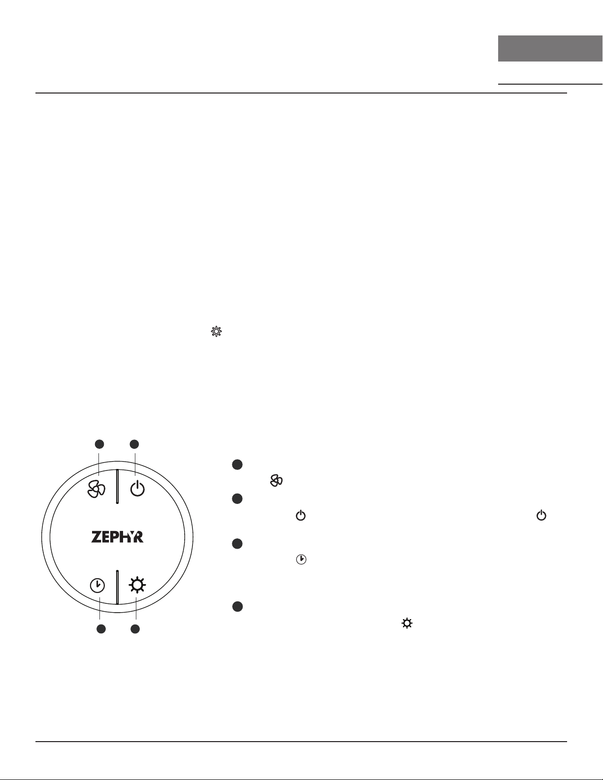
To create a unique link between your hood and remote control please follow these steps.
1. With hood o, press and hold
on the hood until the controls display “REMOTE PAIRING”.
2. Press a button on the remote, and the remote control will be synchronized with the hood.
RF Remote Control Functions
Blower On/
Speed Selection
10 Min Delay O
1
3
Blower On/
2
Power O
4
Lights 1/2/3/O
1
Blower On / Speed Selection
Press to power on blower and cycle through all six blower speeds.
2
Blower On / Power O
By pressing , the blowers will power on at the last speed setting. Press
again and the entire hood will power o, including lights.
Delay O
3
By pressing , the blower and lights will enter Automatic Delay O mode. The
clock icon will illuminate and the controls will display “AUTOMATIC DELAY OFF”.
The blower will change to speed 1 and a 10 minute timer will begin counting
down.
Lights 1/2/3/O
4
Switch between light levels by pressing . Turn o the lights by cycling through
the dierent light levels.
26
Tidal II Use, Care, and Installation Guide
Page 27

Features & Controls
A
-
+
ZEPHYRONLINE.COM
Optional RF Remote Control
RF Remote Features
The RF remote control is equipped with a magnet on the back for easy storage. The remote may be
placed on any magnetic surface such as a refrigerator or the Zephyr remote holder, FIG. C. The
remote holder can be inserted into a standard electrical outlet for easy storage. Note: The remote
holder does not charge the RF remote.
Maximum remote control communication distance is 15 feet from the liner.
FIG. C
RF Remote Maintenance
Clean the remote control using non abrasive detergents.
Follow instructions below for replacing battery. Using a small flat head screwdriver, raise the cover of
the battery door (A) in order to access the battery compartment. FIG. D.
Remove the battery and replace with battery type A23 12V. Negative end of battery should face the
spring inside the remote.
Re-install battery door and recycle old battery.
Tidal II Use, Care, and Installation Guide
FIG. D
27
Page 28

PRO
Maintenance
TIDAL II
WALL
Hood & Filter Cleaning
Surface Maintenance
Ź Do not use corrosive detergents, abrasive detergents or oven cleaners.
Ź Do not use any product containing chlorine bleach or any product containing chloride.
Ź Do not use steel wool or abrasive scrubbing pads which will scratch and damage surface.
Cleaning Stainless Steel
Clean periodically with warm soapy water and clean cotton cloth or micro fiber cloth. Always rub
in the direction of the stainless steel grain. To remove heavier grease build up use a liquid degreaser
detergent.
After cleaning use a non-abrasive stainless steel polish/cleaners, to polish and bu out the stainless
luster and grain. Always scrub lightly, with clean cotton cloth or micro fiber cloth and bu in the
direction of the stainless steel grain.
Ų
The stainless steel baffle filters are intended to trap residue and grease from cooking. Although the
filters should never need replacing, they are required to be cleaned every 30 days or more often
depending on cooking habits.
Filters may be placed in dishwasher at low heat or soaked in hot soapy water Dry filters and re-install
before using hood.
28
Tidal II Use, Care, and Installation Guide
Page 29

ZEPHYRONLINE.COM
1
2
3
ŲĕĘ
1. Push filter toward front of range hood using
handles.
2. Pivot back of filter downward.
3. Remove filter by pulling away from hood.
Ų
Hood Model Part Number Qty. to
Order
AK7400AS 50210039 2
AK7436AS 50210039 2
AK7448AS 50210039 2
Maintenance
Recirculating Kit
ĬŮĭ
Hood Model Part Number Qty. to
Order
AK7400AS ZRC-7000C 1
AK7436AS ZRC-7036C 1
AK7448AS ZRC-7048C 1
Replacement Charcoal Filters also available by
ordering part number Z0F-C002.
See manual included with recirculating kit for more
information.
To order parts, visit us online at
http://store.zephyronline.com.
FIG. E
Tidal II Use, Care, and Installation Guide
29
Page 30

PRO
Maintenance
TIDAL II
WALL
LumiLight LED
In the unlikely event that your LumiLight LED fails, please contact Zephyr to order replacement parts.
See the list of parts and accessories page for part numbers and contact information.
ĬĘĭė
1. Remove pro bae filters.
2. (If applicable) Remove both spacer panels by 2 screws for each spacer panel.
3. Remove light panel by 4 screws.
4. Disconnect LED light quick connector.
5. Push in the two side clips on the ends of the LED light.
6. Push LED light through the light panel opening.
FIG. F
Push the clip
30
Tidal II Use, Care, and Installation Guide
Page 31

ACT™ Conversion
ZEPHYRONLINE.COM
ůĬĻĭ
Some local codes limit the maximum amount of CFM a range hood can move. ACT™ allows you
to control the maximum blower CFM of select Zephyr Ventilation range hoods without the need for
expensive make up air kits. ACT™ enables the installer to easily set the maximum blower speed to one
of two most commonly specified CFM levels; 590, 390, or 290 CFM. The usage of ACT™ may not be
necessary for your installation. Please check your local codes for CFM restrictions.
ACT™ is not available with 1300 CFM dual internal blower option.
CAUTION
Hood must be disconnected from the main power prior to
performing the conversion instructions listed below. Failure to do
so could result in personal injury or damage to the product.
CAUTION
After re-positioning the jumper and powering on the hood, the
CFM cannot be changed again.
Tidal II Use, Care, and Installation Guide
31
Page 32

PRO
ACT™ Conversion
TIDAL II
WALL
Enabling ACT™
To enable ACT™:
1. Before hood installation, gain access to PC board by following the steps shown on FIG. J.
2. Change plastic jumper positioning as shown in FIG. K to set the desired maximum blower CFM.
3. Re-install PC board and continue with hood installation.
4. Remove the appropriate foil CFM sticker included with the hood literature and place inside the
hood body below the wiring diagram or in another clearly visible location.
To verify if your installer enabled ACT™:
1. With hood o, hold the On/O button for three seconds. The Display will show if ACT™ is disabled
and set to the maximum CFM or if ACT™ is enabled and set to one of the restricted maximum CFM
levels of 590, 390 or 290.
2. There should also be a foil label located inside the hood body near the wiring diagram that
indicates the blower CFM.
32
Tidal II Use, Care, and Installation Guide
Page 33

ZEPHYRONLINE.COM
Enabling ACT™
ACT™ Conversion
1. PC board located behind the light panel.
2. (If applicable) Remove both spacer panels by
2 screws for each spacer panel.
3. Remove 4 screws attaching light panel.
2468
1357
PC Board
FIG. J
2468
1357
Jumper 5-6
Max. Blower CFM
590
FIG. K
Jumper Pins
2468
1357
Jumper 7-8
DEFAULT POSITION
2468
1357
Jumper 3-4
Max. Blower CFM
390
Plastic
Jumper
2468
1357
Jumper 1-2
Max. Blower CFM
290
Tidal II Use, Care, and Installation Guide
33
Page 34

PRO
Wiring Diagram
AK7400AS and AK7436AS
Black
White
Green
Body
Black
Single Blower
White
White
Black
Wiring Diagram
Black
Red
Body
Green
TIDAL II
WALL
Motor
ANT
Dual Blower
MOTOR-2
LED
LED
WIFI
WIFI
A. Wi-Fi connection wire
C. Power wire for expansion PCB
D. Power wire for expansion PCB
WHITE
MOTOR-1
K
WHITE
E. Blower connection wire
F. Blower connection wire
G. Control connection wire
B/W
BLACK
BLACKBLACK
B/W
H. Dual blower PCB to switch wire
I. Power lead
J. Dual blower connection wire
K. Blower connection wire
BLACK
WHITE
BLACK
BLACK
WHITE
WHITE
WHITE
34
BODY
GREEN
BLACK
WHITE
Tidal II Use, Care, and Installation Guide
Page 35

ZEPHYRONLINE.COM
Body
Wiring Diagram
AK7448AS Wiring Diagram
Black
White
Green
Single Blower
LED
White
Black
LED
Black
White
LED
Red
Black
Motor
Body
ANT
Green
WIFI
LED
WIFI
MOTOR-2
WHITE
MOTOR-1
Dual Blower
B/W
BLACK
BLACK
WHITE
BODY
GREEN
BLACK
BLACK
WHITE
BLACK
Tidal II Use, Care, and Installation Guide
WHITE
WHITE
A. Wi-Fi connection wire
B. LED PCB wire
C. Power wire for expansion PCB
K
WHITE
D. Power wire for expansion PCB
E. Blower connection wire
F. Blower connection wire
B/W
BLACKBLACK
G. Control connection wire
H. Dual blower PCB to switch wire
I. Power lead
J. Dual blower connection wire
K. Blower connection wire
WHITE
35
Page 36

PRO
Troubleshooting
Possible Problem Possible Cause Solutions
After installation, the
unit doesn’t work.
Light works, but blower
is not turning.
The power source is not turned ON. Make sure the circuit breaker and the unit’s
power is ON.
The power line and the cable
locking connector is not connecting
properly.
The switch board or control board
wirings are disconnected.
The switch board or control board is
defective.
The wires on control board are loose. Make sure the wires on the control board
The blower wire is not connected. Make sure the blower wire is plugged into
The thermally protected system
detects if the blower is too hot to
operate and shuts the blower down.
Damaged capacitor. Change the capacitor.
Check the power connection with the unit is
connected properly.
Make sure the wirings at the switch board
and control board are connected properly.
Change the switch board or control board.
are connected properly.
the molex connector.
The blower will function properly after the
thermally protected system cool down.
TIDAL II
WALL
Blower molex plug pin is not making
contact.
The blower is defective, possibly
seized.
The unit is vibrating. The blower is not secured in place. Tighten the blower in place.
Damaged blower wheel. Replace the blower.
The hood is not secured in place. Check the installation of the hood.
The unit is whistling. A filter is not in the correct position. Adjust the filters until the whistling stops.
The duct pipe connections are not
sealed or connected properly.
The blower is working,
but the LumiLight LEDs
are not.
The LumiLight LED connector is
disconnected.
Defective LumiLight LED. Change the LumiLight LED.
The switch board or control board is
defective.
Disconnect the blower molex plug, check
pins inside plug to see if pin is pushed inside
the plug too far. Reset pin if needed.
Change the blower.
Check the duct pipe connections to be sure
all connections are sealed properly.
Connect the LumiLight LED connector.
Change the switch board or control board.
36
Tidal II Use, Care, and Installation Guide
Page 37

Troubleshooting
ZEPHYRONLINE.COM
Possible Problem Possible Cause Solutions
The hood is not venting
out properly.
The unit turns on by
itself.
Filter is vibrating. Filter is loose. Adjust or change the filter.
RF Remote control does
not work.
Using the wrong size of ducting. Change the ducting to the correct size.
The hood might be hanging to high
from the cook top.
The wind from the opened windows
or opened doors in the surrounding
area are aecting the ventilation of
the hood.
Blockage in the duct opening or
ductwork.
Remote control may be paired
incorrectly.
Someone is controlling the hood via
the Zephyr Connect app.
Spring clip is broken on the filter. Change the spring clip.
Battery is dead. Replace battery with type A23 12v.
Poor communication with the hood. Remote control must be within 15 ft of hood.
Adjust the distance between the cook top
and the bottom of the hood within 24” and
34” range.
Close all the windows and doors to eliminate
the outside wind flow.
Remove all the blocking from the duct work
or duct opening.
Resynchronize the remote control to
connect to a dierent channel
Determine who is controlling the hood with
the app.
The range hood and
user’s device won’t pair
via Bluetooth®.
RF Remote lost communication with
the hood.
Blue antenna wire is not extended. Extend the blue antenna wire behind the
The user’s phone does not have
Bluetooth® enabled.
The user’s phone may be out of
range.
User hasn’t inputted the Bluetooth®
code to successfully pair.
Range hood is not in Bluetooth®
pairing mode.
There are multiple errors preventing
the user’s phone from pairing with
the range hood.
Reset hood and remote by switching power
o at the circuit breaker for 5 minutes.
Place remote on counter top near the hood
and switch the circuit breaker back on.
light panel.
Enable Bluetooth® on the user’s phone.
Move closer towards the range hood.
Enter the pairing code, 123456.
Hold
seconds to put the hood into pairing mode.
Restart the user’s phone and try again.
and simultaneously for 5
Tidal II Use, Care, and Installation Guide
37
Page 38

PRO
Troubleshooting
Possible Problem Possible Cause Solutions
The range hood won’t
connect to Wi-Fi.
User cannot change
Wi-Fi connections.
Cannot bind the hood
to my Zephyr Connect
account.
Zephyr Connect app
won’t register user
inputs.
Zephyr Connect app
stuck on “Loading”.
The user’s router or modem is turned
o.
The user’s router is connected to a 5
GHz wireless frequency.
The user’s coaxial cables are loose. Tighten the coaxial cables connecting to the
The Wi-Fi on the user’s phone is
disabled.
User is connecting to the wrong Wi-Fi
network.
The range hood is not in range of the
Wi-Fi connection.
There are obstacles obstructing the
Wi-Fi signal strength.
The range hood and user’s phone
have already connected.
Only one Zephyr Connect account
can be bound to the hood.
Wi-Fi is unstable and the range hood
may have disconnected.
Range hood is experiencing
diculties connecting to the user’s
phone.
Wi-Fi is unstable and the range hood
may have disconnected.
Range hood is experiencing
diculties connecting to the user’s
phone.
Turn on the router or modem.
Connect to the 2.4 GHz band and attempt
to reconnect.
router or modem.
Enable Wi-Fi on the phone.
Verify that the correct Wi-Fi network is
being connected to. The default Wi-Fi
network name/SSID can be found on the
router.
Move the router and modem closer to the
range hood to increase connection strength.
Move the router and modem closer to
the range hood or move objects that are
directly blocking the pathway to the range
hood. Walls may reduce signal strength.
Enter Bluetooth® settings and forget the
device to reset the process on the phone.
Log in using the Zephyr Connect account
that is already bound to the hood. Multiple
devices can login using the same account.
Ensure the router and modem are both
turned on. Allow the range hood to
reconnect.
Check on the Wi-Fi connection and restart
the application.
Ensure the router and modem are both
turned on. Allow the range hood to
reconnect.
Check on the Wi-Fi connection and restart
the application.
TIDAL II
WALL
38
Tidal II Use, Care, and Installation Guide
Page 39

ZEPHYRONLINE.COM
List of Parts & Accessories
Description Part Number
Replacement Parts
LumiLight LED, 6W Z0B0048
Pro Bae Filter (each) 50210039
Optional Accessories
Dual Internal Blower PBD-1300B
Make-up Air Kit (Single Blower) MUA008A
Make-up Air Kit (Dual Blower) MUA010A
RF Remote Control 14000005
Duct Cover 30” x 12” AK0720
Duct Cover 36” x 12” AK0726
Duct Cover 48” x 12” AK0728
Duct Cover 30” x 24” AK1720
Duct Cover 36” x 24” AK1726
Duct Cover 48” x 24” AK1728
To order parts, visit us online at http://store.zephyronline.com.
Tidal II Use, Care, and Installation Guide
39
Page 40

PRO
Notes
TIDAL II
WALL
40
Tidal II Use, Care, and Installation Guide
Page 41

Limited Warranty
ZEPHYRONLINE.COM
Zephyr Ventilation, LLC (referred to herein as “we” or “us”) warrants to the original consumer purchaser (referred to herein
as “you” or “your”) of Zephyr products (the “Products”) that such Products will be free from defects in materials or
workmanship as follows:
Three Year Limited Warranty for Parts: For three years from the date of your original purchase of the Products, we will
provide, free of charge, Products or parts (including LED light bulbs, if applicable) to replace those that failed due to
manufacturing defects subject to the exclusions and limitations below. We may choose, in our sole discretion, to repair or
replace parts before we elect to replace the Products.
One Year Limited Warranty for Labor: For one
provide, free of charge, the labor cost associated with repairing the Products or parts to replace those that failed due to
manufacturing defects subject to the exclusions and limitations below. After the first year from the date of your original
purchase, you are responsible for all labor costs associated with this warranty.
Warranty Exclusions: This warranty covers only repair or replacement, at our option, of defective Products or parts and
does not cover any other costs related to the Products including but not limited to: (a) normal maintenance and service
required for the Products and consumable parts such as fluorescent, incandescent or halogen light bulbs, mesh and charcoal filters and fuses; (b) any Products or
faulty installation or installation contrary to recommended installation instructions, improper maintenance or repair (other
than by us); (c) commercial or government use of the Products or use otherwise inconsistent with its intended purpose; (d)
natural wear of the finish of the Products or wear caused by improper maintenance, use of corrosive and abrasive cleaning
products, pads, and oven cleaner products; (e) chips, dents or cracks caused by abuse or misuse of the Products; (f) service
trips to your home to teach you how to use the Products; (g) damage to the Products caused by accident, fire, floods, acts
of God; or (h) Custom installations or alterations that impact serviceability of the Products. If you are outside our service
area, additional charges may apply for shipping costs for
travel cost to have a service technician come to your home to repair, remove or reinstall the Products. After the first year
from the date of your original purchase, you are also responsible for all labor costs associated with this warranty. All Products
must be installed by a qualified professional installer to be eligible for warranty repairs or service.
Limitations of Warranty. OUR OBLIGATION TO REPAIR OR REPLACE, AT OUR OPTION, SHALL BE YOUR SOLE
AND EXCLUSIVE REMEDY UNDER THIS WARRANTY. WE SHALL NOT BE LIABLE FOR INCIDENTAL,
CONSEQUENTIAL OR SPECIAL DAMAGES ARISING OUT OF OR IN CONNECTION WITH THE USE OR
PERFORMANCE OF THE PRODUCTS. THE EXPRESS WARRANTIES IN THE PRECEDING SECTION ARE
EXCLUSIVE AND IN LIEU OF ALL OTHER EXPRE
OTHER EXPRESS WARRANTIES FOR THE PRODUCTS, AND DISCLAIM AND EXCLUDE ALL WARRANTIES
IMPLIED BY LAW, INCLUDING THOSE OF MERCHANTABILITY AND FITNESS FOR A PARTICULAR PURPOSE.
Some states or provinces do not allow limitations on the duration of an implied warranty or the exclusion or limitation of
incidental or consequential damages, so the above limitations or exclusions may not apply to you. To the extent that
applicable law prohibits the exclusion of implied warranties, the duration of any applicable implied warranty is limited to the
same three-year and one-year periods described above if permitted by applicable law. Any oral or written description of the
Products is for the sole purpose of identifying the Products and shall not be construed as an express warr
using, implementing or permitting use of the Products, you shall determine the suitability of the Products for the intended
use, and you shall assume all risk and liability whatsoever in connection with such determination. We reserve the right to
use functionally equivalent refurbished or reconditioned parts or Products as warranty replacements or as part of warranty
service. This warranty is not transferable from the original purchaser and only applies to the consumer residence where the
Product was originally installed located in the United States and Canada. This warranty is not extended to resellers.
To Obtain Service Under Limited Warranty: To qualify for warranty service, you must: (a) notify us at the address or
telephone number stated below within 60 days of the discovery of the defect; (b) give the model number and serial
and (c) describe the nature of any defect in the Product or part. At the time of the request for warranty service, you must
present evidence of your proof of purchase and proof of the original purchase date. If we determine that the warranty
exclusions listed above apply or if you fail to provide the necessary documentation to obtain service, you will be responsible
for all shipping, travel, labor and other costs related to the services. This warranty is not extended or restarted upon warranty
repair or replacements.
Please check our website for any additional Product information, www.zephyronline.com.
Zephyr Ventilation Service Department, 2277 Harbor Bay Parkway, Alameda, CA 94502 1-888-880-8368
parts which have been subject to freight damage, misuse, negligence, accident,
year from the date of your original purchase of the Products, we will
warranty repair at our designated service locations and for the
SS WARRANTIES. WE HEREBY DISCLAIM AND EXCLUDE ALL
anty. Prior to
number;
MAY20.0401
Tidal II Use, Care, and Installation Guide
41
Page 42

PRO
Product Registration
Congratulations on the purchase of your
Zephyr product! Please take a moment to
register your new Zephyr product at
www.zephyronline.com/registration
IT’S IMPORTANT
Prompt registration helps in more ways
than one.
Ensures warranty coverage should you need
service.
Ownership verification for insurance purposes.
Notification of product changes or recalls.
TIDAL II
WALL
Zephyr Ventilation | 2277 Harbor Bay Pkwy. | Alameda, CA 94502 | 1.888.880.8368
42
Tidal II Use, Care, and Installation Guide
Page 43

WWW.ZEPHYRONLINE.COM
Tidal II
AK7400AS, AK7436AS, AK7448AS
EN Use, Care, and Installation Guide
FR Guide d’utilisation, d’entretien et d’installation
NOV20.0101
C
Air flow Control Technology
TM
Page 44

PRO
TIDAL II
MUR
2
Tidal II Guide d’utilisation, d’entretien et d’installation
Page 45

ZEPHYRONLINE.COM
Consignes de sécurité ....................................................................... 4-6
Types d’avertissements de sécurité ..................................................... 4
Sécurité générale ...............................................................................4-5
Opération ........................................................................................... 6
Exigences électriques ......................................................................... 6
Déclaration d’interface de la Federal Communication Commission ... 6
Liste de matériel ..................................................................................7
Instructions d’installation ................................................................. 8-20
Feuille de calcul pour le conduit d’aération ......................................... 8
Hauteur de montage, dégagement et gaine ..................................... 9-10
Options de conduits ...........................................................................11
Spécifications de la hotte ...................................................................12
Fourniture électrique ..........................................................................13
Raccord de câble ...............................................................................13
Conversion de conduit horizontal .................................................... 14-16
Installation du double ventilateur PBD-1300B ...................................17-19
Montage de la hotte .......................................................................... 20
Fonctionnalités et commandes .........................................................21-27
Contrôles de proximité ..................................................................... 21-23
Zephyr Connect ..............................................................................24-25
Télécommande RF en option ............................................................26-27
Entretien .......................................................................................... 28-30
Nettoyage de la hotte et du filtre .....................................................28-29
LumiLight LED ................................................................................... 30
Conversion ACT™ .............................................................................31-33
Technologie de contrôle du débit d’air (ACT™) ....................................31
Activer ACT™ ...................................................................................32-33
Schéma de câblage ......................................................................... 34-35
Dépannage ..................................................................................... 36-38
Liste des pièces et accessoires ........................................................... 39
Remarques .........................................................................................40
Garantie limitée ................................................................................. 41
Enregistrement du produit .................................................................. 42
Table des matières
Page
Tidal II Guide d’utilisation, d’entretien et d’installation
3
Page 46

PRO
Consignes de sécurité
LISEZ ET CONSERVEZ CES INSTRUCTIONS
Votre sécurité et celle des gens qui vous entourent sont très
importantes.
Ce manuel contient de nombreux messages de sécurité relatifs
à votre appareil. Lisez tous les messages et conformez-vous-y
en tout temps.
Voici le symbole d’alerte à la sécurité. Ce symbole vous informe
de possibles dangers qui pourraient entraîner de graves lésions
corporelles ou la mort. Tous les messages de sécurité suivent
le symbole d’alerte à la sécurité et comportent les mots «
DANGER », « AVERTISSEMENT » ou « ATTENTION ».
DANGER
Le mot « danger » signifie que le fait de ne pas tenir compte
de l’énoncé de sécurité peut entraîner une blessure grave ou
la mort.
AVERTISSEMENT
TIDAL II
MUR
AVERTISSEMENT
AVERTISSEMENT - POUR RÉDUIRE LES RISQUES D’INCENDIE,
DE CHOC ÉLECTRIQUE OU DE BLESSURES AUX PERSONNES,
RESPECTEZ LES SUIVANTS:
a) N’utilisez cet appareil que de la manière prévue par le
fabricant. Si vous avez des questions, contactez le fabricant.
b) Avant l’entretien ou le nettoyage de l’unité, coupez
l’alimentation au panneau de service et verrouillez les moyens
de déconnexion de service pour éviter toute mise sous tension
accidentelle. Lorsque le moyen de déconnexion de service
ne peut pas être verrouillé, fixez solidement un dispositif
d’avertissement bien visible, tel qu’une étiquette, au panneau
de service.
ATTENTION
Pour Une Ventilation Générale Uniquement. Ne Pas Utiliser
Pour Évacuer Des Matières Et Des Vapeurs Dangereuses Ou
Explosives. Soyez prudent lorsque vous utilisez des produits
de nettoyage pour détergents. Convient pour une utilisation
dans la zone de cuisson domestique.
Le mot « avertissement » signifie que le fait de ne pas
tenir compte de l’énoncé de sécurité peut entraîner des
dommages importants au produit, une lésion corporelle
grave ou la mort.
ATTENTION
Le mot « attention » signifie que le fait de ne pas tenir
compte de l’énoncé de sécurité peut entraîner une lésion
corporelle mineure ou modérée, ou encore des dommages
au produit ou à la propriété.
Sécurité générale
ATTENTION
Pour réduire le risque d’incendie ou de choc électrique,
n’utilisez pas ce ventilateur avec un dispositif de commande
à semi-conducteurs.
AVERTISSEMENT
AVERTISSEMENT - POUR RÉDUIRE LE RISQUE D’INCENDIE DE
GRAISSE SUR LE HAUT DE CUISINIÈRE:
a) Ne laissez jamais les unités de surface sans surveillance
à des réglages élevés. Les débordements provoquent de la
fumée et des débordements graisseux qui peuvent s’enflammer.
Chauer les huiles lentement à des réglages faibles ou
moyens.
b) Allumez toujours la hotte lorsque vous cuisinez à feu vif
ou lorsque vous flambez des aliments. (c’est-à-dire Crêpes
Suzette, Cerises Jubilee, Boeuf au Poivre Flambé »).
c) Nettoyez fréquemment les ventilateurs de ventilation. La
graisse ne doit pas s’accumuler sur le ventilateur ou le filtre.
d) Utilisez une taille de casserole appropriée. Utilisez toujours
des ustensiles de cuisine adaptés à la taille de l’élément de
surface.
4
Tidal II Guide d’utilisation, d’entretien et d’installation
Page 47

ZEPHYRONLINE.COM
Consignes de sécurité
LISEZ ET CONSERVEZ CES INSTRUCTIONS
AVERTISSEMENT
AVERTISSEMENT - POUR RÉDUIRE LE RISQUE DE BLESSURE
DES PERSONNES EN CAS D’INCENDIE DE GRAISSE SUR LE
HAUT DE LA CUISINIÈRE, RESPECTEZ CE QUI SUIT:
a) DES FLAMMES PLUS INTELLIGENTES avec un couvercle bien
ajusté, une plaque à biscuits ou un plateau en métal, puis
éteignez le brûleur. FAITES ATTENTION À ÉVITER LES BRÛLURES.
Si les flammes ne s’éteignent pas immédiatement, ÉVACUER ET
APPELER LE DÉPARTEMENT DES INCENDIES.
b) NE JAMAIS RAMASSER UNE PLAQUE ENFLAMME - Vous
pourriez être brûlé.
c) N’UTILISEZ PAS D’EAU, ni de torchons ou de serviettes
humides - une violente explosion de vapeur en résultera.
d) Utilisez un extincteur UNIQUEMENT si:
1) Vous savez que vous possédez un extincteur de classe
ABC et vous savez déjà comment l’utiliser.
2) Le feu est petit et contenu dans la zone où il a
commencé.
3) Le service d’incendie est appelé.
4) Vous pouvez combattre le feu dos à une sortie
Basé sur “Kitchen Firesafety Tips” publié par la NFPA.
AVERTISSEMENT
AVERTISSEMENT
AVERTISSEMENT - POUR RÉDUIRE LES RISQUES D’INCENDIE,
DE DÉCHARGE ÉLECTRIQUE OU DE BLESSURES AUX
PERSONNES, RESPECTEZ CE QUI SUIT:
a) Les travaux d’installation et le câblage électrique doivent
être eectués par des personnes qualifiées conformément à
tous les codes et normes applicables, y compris la construction
résistant au feu.
b) Une quantité d’air susante est nécessaire pour une
combustion et une évacuation correctes des gaz par le conduit
de fumée (cheminée) de l’équipement à combustible pour
empêcher le refoulement. Suivez les directives et les normes
de sécurité du fabricant de l’équipement de chauage, telles
que celles publiées par la National Fire Protection Association
(NFPA), l’American Society for Heating, Refrigeration and Air
Conditioning Engineers (ASHRAE) et les autorités locales du
code.
c) Lorsque vous coupez ou percez dans un mur ou un plafond,
n’endommagez pas le câblage électrique et les autres services
publics cachés.
d) Les ventilateurs à conduit doivent toujours être ventilés vers
l’extérieur.
e) Si cet appareil doit être installé au-dessus d’une baignoire
ou d’une douche, il doit être marqué comme approprié pour
l’application et être connecté à un circuit de dérivation protégé
par un disjoncteur de fuite à la terre (GFCI).
AVERTISSEMENT
POUR RÉDUIRE LES RISQUES D’INCENDIE, UTILISEZ
UNIQUEMENT DES CONDUITS MÉTALLIQUES.
ATTENTION
Pour réduire les risques d’incendie et pour évacuer
correctement l’air extérieur, ne pas évacuer l’air évacué dans
les espaces à l’intérieur des murs, plafonds, greniers, vides
sanitaires ou garages.
Prop. 65 Avertissement pour les résidents de Californie: Ce
produit peut contenir des produits chimiques reconnus par
l’État de Californie comme pouvant provoquer le cancer,
des malformations congénitales ou d’autres troubles de la
Tidal II Guide d’utilisation, d’entretien et d’installation
AVERTISSEMENT
reproduction.
5
Page 48

PRO
Consignes de sécurité
TIDAL II
LISEZ ET CONSERVEZ CES INSTRUCTIONS
Opération
Ź Laissez toujours les grilles de sécurité et les filtres en place. Sans ces composants, les souantes en fonctionnement pourraient
s’accrocher aux cheveux, aux doigts et aux vêtements amples.
Ź Le fabricant décline toute responsabilité en cas de non-respect des instructions données ici pour l’installation, la maintenance et
l’utilisation appropriée du produit. Le fabricant décline en outre toute responsabilité en cas de blessure due à une négligence et la
garantie de l’unité expire automatiquement en raison d’un mauvais entretien.
REMARQUE: veuillez consulter www.zephyronline.com pour les révisions avant d’eectuer tout travail personnalisé.
Exigences électriques
Important:
Ź Respectez tous les codes et ordonnances en vigueur.
Ź Il est de la responsabilité du client d’en prendre connaissance ci-dessous:
Ź Pour contacter un installateur électrique qualifié.
Ź Pour garantir que l’installation électrique est adéquate et conforme au National Electrical Code, ANSI / NFPA 70 dernière édition *
ou aux normes CSA C22.1-94, Code canadien de l’électricité, partie 1 et C22.2 No.0-M91 - dernière édition ** et tous les codes et
ordonnances locaux.
Ź Si les codes le permettent et qu’un fil de terre séparé est utilisé, il est recommandé qu’un électricien qualifié détermine que le
chemin de terre est adéquat.
Ź Ne pas mettre à la terre un tuyau de gaz.
Ź Vérifiez auprès d’un électricien qualifié si vous n’êtes pas sûr que la hotte est correctement mise à la terre.
Ź Ne pas avoir de fusible dans le circuit neutre ou de terre.
Ź Cet appareil nécessite une alimentation électrique de 120 V à 60 Hz et est connecté à un circuit de dérivation individuel
correctement mis à la terre protégé par un disjoncteur de 15 ou 20 ampères ou un fusible temporisé. Le câblage doit être à 2 fils
avec mise à la terre. Veuillez également vous référer au schéma électrique du produit.
Ź Un connecteur de verrouillage de câble (non fourni) peut également être requis par les codes locaux. Vérifiez les exigences locales,
achetez et installez le connecteur approprié si nécessaire.
* National Fire Protection Association Batterymarch Park, Quincy, Massachusetts 02269
** CSA International 8501 East Pleasant Valley Road, Cleveland, Ohio 44131-5575
MUR
Déclaration d’interface de la Federal Communication Commission
Ź Cet équipement a été testé et déclaré conforme aux limites d’un appareil numérique de classe B, conformément à la partie 15 des
règles FCC. Ces limites sont conçues pour fournir une protection raisonnable contre les interférences nuisibles dans une installation
résidentielle.
Ź Cet équipement génère, utilise et peut émettre de l’énergie radiofréquence et, s’il n’est pas installé et utilisé conformément aux
instructions, peut provoquer des interférences nuisibles aux communications radio. Cependant, il n’y a aucune garantie que
des interférences ne se produiront pas dans une installation particulière. Si cet équipement cause des interférences nuisibles à
la réception de la radio ou de la télévision, ce qui peut être déterminé en éteignant et en rallumant l’équipement, l’utilisateur est
encouragé à essayer de corriger les interférences par l’une des mesures suivantes:
Ź Réorientez ou déplacez l’antenne de réception.
Ź Augmentez la séparation entre l’équipement et le récepteur.
Ź Connectez l’équipement à une prise sur un circuit diérent de celui sur lequel le récepteur est connecté.
Ź Consultez le revendeur ou un technicien radio / TV expérimenté pour obtenir de l’aide.
6
Tidal II Guide d’utilisation, d’entretien et d’installation
Page 49

ZEPHYRONLINE.COM
Liste de matériel
Pièces fournies
Quantité Partie
1Hotte
2 Filtres bae Pro (AK7400AS, AK7436AS)
3 Filtres bae Pro (AK7448AS)
2 LumiLight LED, 6W (préinstallé) (AK7400AS, AK7436AS)
4 LumiLight LED, 6 W (préinstallé) (AK7448AS)
1 Clapet anti-retour rond de 8 po (préinstallé)
1 Collier rectangulaire 3-1/4 po x 10 po avec amortisseur
1 Moteur de souante simple (préinstallé)
1 Plaque de recouvrement supérieure (pour gaine horizontale)
1 Pack matériel
#6 x 2 po (4)
#6 x 1-1/2 po (4)
#6 x 1 po (4)
M3.5 x 8 (8)
Capuchons de connexion (3)
Pièces non fournies
Conduits, conduits et tous les outils d'installation
Raccord de câble (si requis par les codes locaux)
Kit d'extension de couvercle de conduit
Kit de recirculation
Télécommande RF
Moteur à double souante
Panneau en bois pour accrocher la hotte (LxPxH)
3/16 x 3/8 (4)
AK7400AS: 27 po x 1/2 po x 4 po
AK7436AS: 33 po x 1/2 po x 4 po
AK7448AS : 45 po x 1/2 po x 4 po
Tidal II Guide d’utilisation, d’entretien et d’installation
7
Page 50

PRO
Instructions d’installation
Feuille de calcul pour le conduit d’aération
Pièces de conduit
3- 1/ 4” x 10”
rect., droit
6”, 7”, 8”, 10”
circ., droit
3- 1/ 4” x 10”
rect.,
coude à 90º
3- 1/ 4” x 10”
rect.,
coude à 45º
3- 1/ 4” x 10”
rect.,
coude plat
à 90º
7” to 6” or
8” to 7” circ.
reducteur
conique
6”, 7“, 8”
circ.
bouchone de
l’air
6”, 7”, 8”, 10”
circ.,
coude à 90º
6”, 7”, 8”, 10”
coude à 45º
Longueur x
Nombre utilisé
1 pi x ( ) =
1 pi x ( ) =
15 pi x ( ) =
9 pi x ( ) =
24 pi x ( ) =
25 pi x ( ) =
15
pi x ( ) =
15 pi
9 pi x ( ) =
=
x ( ) =
Sous-total - colonne 1=
To t a l
pi
pi
pi
pi
pi
pi
pi
pi
pi
pi
Pièces de conduit
6” circ. à
rect. de
3-1/4" x 10"
6” circ. à
rect. de
3-1/4" x 10",
coude à 90º
6” circ. à
rect. de
3-1/4" x 10"
6” circ. à
rect. de
3-1/4" x 10",
coude à 90º
7” circ. à
rect. de
3-1/4" x 10"
7” circ. à
rect. de
3-1/4" x 10",
coude à 90º
3-1/ 4” x 10”
embout mural
rect./registre
6”, 7”, 8”, 10”
embout
mural
circ./registre
6”, 7”, 8”, 10”
chapeau de
toiture circ.
Longueur x
Nombre utilisé
5 pi x ( ) =
20 pi x ( ) =
1 pi x ( ) =
16 pi x ( ) =
8 pi x ( ) =
23 pi x ( ) =
30 pi x ( ) =
30 pi x ( ) =
30 pi x ( ) =
=
To t a l
TIDAL II
MUR
pi
pi
pi
pi
pi
pi
pi
pi
pi
Longueur maximale du conduit d’aération :
Pour un mouvement d’air convenable, la longueur totale d’un conduit
d’aération ne devrait pas compter plus que l’équivalent de 150 pieds.
8
Tidal II Guide d’utilisation, d’entretien et d’installation
Sous-total - colonne 2 =
Sous-total - colonne 1 =
Total du conduit =
pi
pi
pi
Page 51

Instructions d’installation
ZEPHYRONLINE.COM
Hauteur de montage, dégagement et gaine
36 po
24 po min.
34 po max.
Tidal II Guide d’utilisation, d’entretien et d’installation
9
Page 52

PRO
Instructions d’installation
TIDAL II
MUR
Hauteur de montage, dégagement et gaine
Un conduit rond d’au moins 8 ”ou un conduit rectangulaire de 3-1 / 4” x 10 ”est recommandé pour
maintenir une ecacité maximale du débit d’air pour un seul ventilateur et un conduit rond de 10”
pour un double ventilateur interne pour les conduits verticaux et horizontaux.
Utilisez toujours uniquement des conduits métalliques de type rigide. Les conduits flexibles peuvent
restreindre le débit d’air jusqu’à 50%.
Utilisez également la feuille de calcul des gaines (à la page 11) pour calculer la longueur totale des
gaines disponibles lorsque vous utilisez des coudes, des transitions et des capuchons.
TOUJOURS, lorsque cela est possible, réduire le nombre de transitions et de virages. Si un long trajet
de conduit est requis, augmentez la taille du conduit de 8 po à 10 po.
Si des virages ou des transitions sont nécessaires; installer aussi loin que possible de la sortie du
conduit de la hotte et aussi loin que possible entre les deux.
La hauteur minimale de montage entre le haut de la cuisinière et le bas de la hotte ne doit pas être
inférieure à 24 po.
La hauteur de montage maximale ne doit pas dépasser 34 po.
Il est important d’installer la hotte à la bonne hauteur de montage. Les hottes montées trop bas
peuvent entraîner des dommages causés par la chaleur et un risque d’incendie; tandis que les hottes
montées trop haut seront diciles à atteindre et perdront leurs performances et leur ecacité.
Si disponible, reportez-vous également aux exigences de dégagement en hauteur du fabricant de la
cuisinière et à la hauteur de montage recommandée de la hotte au-dessus de la cuisinière. Vérifiez
toujours vos codes locaux pour toute diérence.
Kit d’extension de couvercle de conduit disponible pour des hauteurs de plafond allant jusqu’à 12
pieds. Consultez la section Liste des pièces et accessoires pour connaître le numéro de pièce et les
informations de commande.
Pour les dommages liés à l’expédition et à l’installation:
Ź Veuillez inspecter complètement l’unité pour déceler tout dommage avant l’installation. Si
l’appareil est endommagé lors de l’expédition, renvoyez-le au magasin où il a été acheté pour
réparation ou remplacement.
Ź Si l’appareil est endommagé par le client, la réparation ou le remplacement est à la charge du
client.
Ź Si l’unité est endommagée par l’installateur (si autre que le client), la réparation du remplacement
doit être eectuée par arrangement entre le client et l’installateur.
10
Tidal II Guide d’utilisation, d’entretien et d’installation
Page 53

Instructions d’installation
ZEPHYRONLINE.COM
Options de conduits
ATTENTION
Risque d’incendie: NE JAMAIS évacuer l’air ni terminer de
conduits dans des espaces entre les murs, les vides sanitaires,
les plafonds, les greniers ou les garages. Tout l’échappement
doit être canalisé vers l’extérieur, à moins d’utiliser l’option de
recirculation.
Ź Utilisez uniquement des conduits métalliques rigides à paroi simple.
Ź Fixez toutes les connexions avec des vis à tôle et collez tous les joints avec du ruban argenté ou du
ruban adhésif.
Reprise d’air condui
Pente de la toiture
avec solin et chapeau
Retombee de plafond
ou vide sanitaire
Conduit arriere
Bouch d’aeration
de mur lateral avec
clapet
antirefoulement
Tidal II Guide d’utilisation, d’entretien et d’installation
11
Page 54

PRO
Instructions d’installation
¯Ů
Haut
27-7/8 po (30 po)
33-7/8 po (36 po)
1 po
1-1/8 po
8-9/16 po
45-13/16 po (48 po)
6 po
11-9/16 po
2-5/8 po
*7-7/8 po
**10-3/8 po
TIDAL II
MUR
Côté
12 po
18 po
12-9/16 po
4 po
3-3/8 po (30 po)
6-3/8 po (36 po)
12-3/8 po (48 po)
1-11/16 po
*9-1/2 po
**14-3/16 po
29-15/16 po (30 po)
35-7/8 po (36 po)
47-7/8 po (48 po)
Retour
*7-3/4 po
**9-15/16 po
*7-7/8 po
**10-3/8 po
***3-3/16 po
3-1/4 po
1-11/16 po
16-1/8 po
* Conduit rond de 8 po
** Conduit rond de 10 po
*** Gaine rectangulaire
13-9/16 po
24 po
Retour
5-1/4 po
18 po
12
*9-1/2 po
**14-3/16 po
***9-7/8 po
21-1/4 po
27-3/8 po (30 po, 36 po)
35-1/4 po (48 po)
Tidal II Guide d’utilisation, d’entretien et d’installation
Page 55

Instructions d’installation
ZEPHYRONLINE.COM
Fourniture électrique
ATTENTION
Le câblage électrique doit être eectué par des personnes
qualifiées conformément à tous les codes et normes applicables.
Cette hotte doit être correctement mise à la terre. Coupez
l’alimentation électrique à l’entrée de service avant le câblage.
Pour votre sécurité personnelle, retirez le fusible de la maison ou ouvrez le disjoncteur avant de
commencer l’installation. N’utilisez pas de rallonge ni de fiche d’adaptateur avec cet appareil.
Suivez les codes électriques nationaux ou les codes et règlements locaux en vigueur.
Cet appareil nécessite une alimentation électrique de 120 V 60 Hz et est connecté à un circuit de
dérivation individuel correctement mis à la terre, protégé par un disjoncteur de 15 ou 20 ampères
ou un fusible temporisé. Le câblage doit être à 2 fils avec terre. Veuillez également vous référer au
schéma électrique étiqueté sur le produit.
Raccord de câble
Un connecteur de verrouillage de câble (non fourni) peut être requis par les codes locaux. Vérifiez les
exigences et les codes locaux, achetez et installez le connecteur approprié si nécessaire. (FIG. A)
Raccord de câble
FIG. A
Tidal II Guide d’utilisation, d’entretien et d’installation
13
Page 56

PRO
Instructions d’installation
TIDAL II
MUR
Conversion de conduit horizontal
Par défaut, le Tidal II est préconfiguré pour un conduit vertical rond de 8 po. Ces étapes sont pour des
conduits horizontaux ronds de 8 po et rectangulaires de 3-1/4 po x 10 po. Si vous continuez avec un
conduit vertical, veuillez ignorer ces étapes.
1. Débranchez la fiche du
ventilateur.
2. Retirez les (4) vis de l’intérieur
du corps de la hotte pour fixer
la plaque de souante unique
au dessus du corps de la hotte.
Retirez le ventilateur simple et la
plaque de ventilateur simple.
3. À l’aide d’un tournevis à tête
plate, retirez la plus petite plaque
à défoncer rectangulaire (A) pour
B
A
un conduit rectangulaire de 3-1/4
po x 10 po ou la plus grande
plaque à défoncer (B) pour un
conduit rond de 8 po située à
l’arrière du capuche.
14
Tidal II Guide d’utilisation, d’entretien et d’installation
Page 57

Instructions d’installation
ZEPHYRONLINE.COM
Conversion de conduit horizontal
4. Retirez les (4) vis fixant le
ventilateur à la plaque du
ventilateur. Tournez le ventilateur
de 180 degrés et rattachez-le à la
plaque du ventilateur.
5. Positionnez un ventilateur
simple avec une seule plaque
de ventilateur comme illustré.
Assurez-vous de rentrer la plaque
de ventilateur unique dans les
languettes à l’arrière de la hotte.
Fixez la plaque de ventilateur
unique à l’arrière de la hotte
à l’aide des (4) vis retirées de
l’étape 2.
6. Fixez un collier de conduit rond
de 8 “ou un collier de conduit
rectangulaire de 3-1/4 po x 10 po
à l’arrière du corps de la hotte à
l’aide de (4) vis M3,5 x 8.
Tidal II Guide d’utilisation, d’entretien et d’installation
15
Page 58

PRO
Instructions d’installation
Conversion de conduit horizontal
7. Depuis l’intérieur du corps de
TIDAL II
MUR
la hotte, placez la plaque de
recouvrement supérieure vers le
haut du corps de la hotte. Depuis
l’extérieur du corps de la hotte,
fixez la plaque de recouvrement
supérieure au dessus du corps de
la hotte à l’aide de (4) vis 3/16 x
3/8.
8. Branchez la fiche du ventilateur.
16
Tidal II Guide d’utilisation, d’entretien et d’installation
Page 59

Instructions d’installation
ZEPHYRONLINE.COM
Installation de deux ventilateurs PBD-1300B
Cette hotte de cuisinière est équipée de série d’une option de conduit vertical à un seul ventilateur.
Pour passer d’un conduit vertical à une seule souante à un conduit vertical à double souante,
veuillez suivre les instructions ci-dessous.
Le kit double souante PBD-1300B est compatible avec toutes les tailles Tidal II.
1. Retirez les filtres déflecteurs et, le
cas échéant, retirez les panneaux
latéraux. Débranchez la fiche du
ventilateur.
2. Retirez les (4) vis en haut du corps
de la hotte fixant le ventilateur à
la plaque du ventilateur. Retirez le
ventilateur de l’intérieur du corps
de la hotte.
3. Retirez les (4) vis de l’intérieur
du corps de la hotte fixant la
plaque du ventilateur au corps
de la hotte. Retirez la plaque du
ventilateur.
4. Installez la plaque de ventilateur
double du kit PBD-1300B dans
le corps de la hotte. Fixez avec
(4) vis précédemment retirées de
l’étape 3.
Tidal II Guide d’utilisation, d’entretien et d’installation
17
Page 60

PRO
Instructions d’installation
Installation de deux ventilateurs PBD-1300B
5. Installez le ventilateur
précédemment retiré sur un
côté de la plaque de ventilateur
double et fixez-le à l’aide des (4)
vis précédemment retirées de
l’étape 2.
6. Installez le ventilateur du kit
PBD-1300B sur l’autre côté de la
plaque de ventilateur double à
l’aide de (4) vis 3/16 x 3/8.
TIDAL II
MUR
7. Emplacements de montage de
deux vis de ventilateur.
8. Retirez les (5) vis pour retirer
le panneau lumineux. Installez
le circuit imprimé du double
ventilateur à l’intérieur du corps
de la hotte.
18
Tidal II Guide d’utilisation, d’entretien et d’installation
Page 61

Instructions d’installation
ZEPHYRONLINE.COM
Installation de deux ventilateurs PBD-1300B
9. Reportez-vous à la section
page 32-33 pour cette étape.
Connectez le câblage du
double ventilateur, y compris
les deux fiches du ventilateur,
le connecteur à 6 broches
du câble du ventilateur (E),
le câble du commutateur du
ventilateur double (H), le cordon
d’alimentation noir à une broche
du double ventilateur (K) et le
cordon d’alimentation blanc à
une broche (F) au PCB double
ventilateur.
10. Placez l’adaptateur rond de 10 po
(inclus avec le PBD-1300B) sur le
dessus de la hotte et fixez-le avec
(4) vis M3,5 x 8.
REMARQUE: Pour fixer l’adaptateur de transition de 10 po au haut de la hotte, une découpe de 14-1/2
po de largeur x 10-1/2 po de profondeur devra être faite dans le bas de l’armoire.
Si les dimensions internes de l’armoire empêchent cette taille de découpe, alors l’adaptateur de
transition de 10 pouces peut être monté sur le bas de l’armoire plutôt que sur le haut de la hotte.
Les dimensions de la découpe pour ce type d’installation sont de 13-1/4 po de largeur x 6-1/4 po de
profondeur.
Tidal II Guide d’utilisation, d’entretien et d’installation
19
Page 62

PRO
C/L
C/L
A
B
16-7/8 po
min
24 po
4 po
planche de bois
Instructions d’installation
TIDAL II
MUR
Montage de la hotte
Si la hotte à recirculation de la cuisinière, reportez-vous au manuel inclus avec le kit de recirculation
ZRC-70xxC ou sur notre site Web avant d’installer la hotte.
ATTENTION
Au moins deux installateurs sont nécessaires en raison
du poids et de la taille de la hotte.
1. Sélectionnez l’application de conduit préférée
(verticale ou horizontale) et préparez la hotte. Retirez la
vis de sécurité sur le dessus du corps de la hotte.
2. Choisissez la hauteur désirée au-dessus de la surface
de cuisson (24 ”min). Mettre à niveau et marquer le bas
du capot, ligne A (FIG. B)
3. Prune et marquez la ligne centrale sur le mur.
4. Mettez à niveau et marquez le dessus de la planche de
bois, ligne B (FIG. B) à 16-7 / 8 ”de la ligne A.
5. Marquez la ligne centrale de la planche de bois. Centrez et alignez le haut de la planche avec
la ligne B. Fixez la planche de bois aux montants à l’aide de (4) vis à bois n ° 6. Dimensions du
panneau de bois: (L x P x H)
30 po: 27 po x 1/2 po x 4 po
36 po: 33 po x 1/2 po x 4 po
48 po: 45 po x 1/2 po x 4 po
6. Préparez le tuyau de conduit et les découpes de conduit dans l’armoire supérieure si nécessaire ou
au mur si la hotte est à conduit horizontalement. Préparez le câblage électrique et les découpes
électriques dans l’armoire supérieure si nécessaire ou au mur si un raccordement électrique
horizontal est nécessaire. Reportez-vous aux spécifications de la hotte à la page 15 pour les
dimensions.
7. Montez la hotte sur une planche de bois et fixez-la à l’aide de (4) vis à bois no 6. Fixez davantage
la hotte au mur à travers les trous de vis du bas du corps à l’aide de (2) vis à bois n°6.
8. Installer les conduits électriques et les conduits et sceller avec du ruban adhésif en aluminium.
9. Si vous utilisez une télécommande RF, retirez les filtres déflecteurs et retirez le panneau lumineux à
l’aide de (4) vis et étendez le fil d’antenne bleu. Il n’est pas nécessaire de le sécuriser. Réinstaller le
panneau lumineux et les filtres déflecteurs.
FIG. B
10. Mettez la hotte sous tension et vérifiez s’il y a des fuites autour du ruban adhésif.
20
Tidal II Guide d’utilisation, d’entretien et d’installation
Page 63

ZEPHYRONLINE.COM
Contrôles de proximité
Allumer Lumières
CAPTEUR DE PROXIMITÉ
Ź Lorsque vous vous approchez de la hotte lorsqu’elle est hors tension, les icônes
d’alimentation, de diminution du ventilateur, d’augmentation du ventilateur et d’éclairage
s’allument et «BONJOUR» apparaît sur l’écran LCD pendant 2 secondes.
Ź Les icônes restent allumées pendant que le capteur de proximité détecte quelqu’un près
de la hotte. Si personne ne se trouve à proximité de la hotte et que ni le ventilateur ni
les lumières ne sont allumés, les icônes s’éteindront après 60 secondes et «GOODBYE»
apparaîtra sur l’écran LCD pendant 2 secondes.
Fonctionnalités et commandes
űÙ
Ajuster 6 niveaux de vitesse
Ź Les icônes ne disparaîtront pas tant que le ventilateur et les lumières ne seront pas
éteints.
ICÔNES DE CONTRÔLE
Allumer
Ź Appuyez sur l’icône d’alimentation pour allumer ou éteindre le ventilateur et les lumières.
Ź La hotte a une fonction de mémoire pour mémoriser les derniers réglages utilisés pour le
ventilateur et les lumières.
Ź Après avoir appuyé sur l’icône d’alimentation pour éteindre la hotte, «GOODBYE» apparaîtra
sur l’écran LCD pendant 2 secondes.
Ź L’icône 3s sous l’icône d’alimentation ne s’allume que lorsque le ventilateur est sous
tension. Il s’agit d’un indicateur permettant d’activer le délai d’arrêt automatique
en appuyant sur le bouton d’alimentation et en le maintenant enfoncé pendant 3
secondes.
Diminuer la vitesse du ventilateur
Ź Appuyez sur l’icône pour diminuer la vitesse du ventilateur de 6, 5, 4, 3, 2, 1, arrêt.
Augmenter la vitesse du ventilateur
Ź Appuyez sur l’icône pour augmenter la vitesse du ventilateur de OFF, 1, 2, 3, 4, 5, 6.
Tidal II Guide d’utilisation, d’entretien et d’installation
21
Page 64

PRO
Fonctionnalités et commandes
Contrôles de proximité
Lumières
Ź Appuyez sur l’icône des lumières pour changer le niveau d’éclairage de 1, 2, 3, désactivé.
AFFICHER ICÔNES et FONCTIONS
Ů
Ź L’icône de la cloche de notification s’allumera lorsqu’une action doit être entreprise. Appuyez
sur l’icône pour parcourir les notifications. La cloche de notification restera allumée jusqu’à
ce que toutes les notifications soient résolues. La cloche de notification ne s’allume pas
lorsque le capot et les commandes sont hors tension.
Bluetooth®
Ź L’icône Bluetooth® illumine l’appareil lorsqu’il est connecté à la hotte via Bluetooth®. Les
mots «BLUETOOTH CONNECTED» ou «BLUETOOTH DISCONNECT» apparaissent sur l’écran
LCD chaque fois que la connexion change.
TIDAL II
MUR
Wi-Fi
Ź L’icône Wi-Fi s’allume lorsque la hotte est connectée au Wi-Fi. Les mots «WIFI CONNECTED»
ou «WIFI DISCONNECTED» apparaîtront sur l’écran LCD chaque fois que la connexion
change, ce qui sera géré via l’application Zephyr Connect.
Retard automatique désactivé
Ź Pendant que le ventilateur est en marche, maintenez enfoncé pendant 3 secondes
pour activer la minuterie d’extinction. Le ventilateur passera à la vitesse 1, l’achage de
la minuterie s’allumera, l’écran LCD achera «AUTOMATIC DELAY OFF» et la minuterie
commencera à compter à rebours à partir de 10 minutes. Une fois que la minuterie atteint 0,
le ventilateur et les lumières s’éteignent.
Ź La minuterie de la fonction d’arrêt automatique du délai commence à 10 minutes par défaut.
L’application Zephyr Connect fournit les options pendant 5 ou 10 minutes.
L’air pur
Ź Lorsque le ventilateur est éteint, appuyez simultanément sur et pendant 3 secondes
pour activer ou désactiver la fonction CleanAir. L’écran LCD achera «CLEAN AIR ENABLED»
ou «CLEAN AIR DISABLED».
22
Ź Lorsqu’il est activé, le ventilateur se met en marche à la vitesse 1 toutes les 4 heures pendant
10 minutes. Pendant que le ventilateur fonctionne, l’écran LCD achera «CLEAN AIR
ACTIVE» et l’icône CleanAir s’allumera.
Tidal II Guide d’utilisation, d’entretien et d’installation
Page 65

ZEPHYRONLINE.COM
Contrôles de proximité
¯ŮĻ
Ź La technologie de contrôle du flux d’air (ACT™) permet à l’installateur de régler le CFM
maximum du ventilateur pour s’aligner sur les codes et réglementations locaux. Lorsque
le ventilateur est éteint, appuyez et maintenez
ACT™.
Ź ACT 290 = 3 vitesses, ACT 390 = 4 vitesses, ACT 590 = 5 vitesses.
Ů£
Ź Après 60 heures d’utilisation du ventilateur, l’icône de la cloche de notification s’allumera.
Lorsque vous appuyez sur la cloche, l’écran LCD alterne entre l’achage de «CLEAN
GREASE FILTER» et de «HOLD DOWN TO RESET» toutes les 2 secondes. Si aucune action
n’est entreprise pendant 30 secondes, l’écran s’éteint et l’icône de la cloche de notification
reste allumée.
Fonctionnalités et commandes
pendant 3 secondes pour acher l’état
Ź Pour maintenir et réinitialiser, appuyez et maintenez le bouton de diminution du
ventilateur pendant 3 secondes pour réinitialiser. L’application Zephyr Connect ore
la possibilité de réinitialiser le rappel.
ĚŮ£
Ź Maintenez et pendant 3 secondes pour activer ou désactiver le mode de recirculation
qui vous rappellera de remplacer le filtre à charbon. L’écran LCD achera «RECIRCULATING
ENABLED» pour activer et «RECIRCULATING DISABLE» pour désactiver pendant 2 secondes.
Ź Après 200 heures d’utilisation du ventilateur, l’icône de la cloche de notification s’allumera.
Lorsque vous appuyez sur la cloche, l’écran LCD alterne entre l’achage de «REPLACE
CHARCOAL FLTR» et «HOLD UP TO RESET» toutes les 2 secondes. Si aucune action n’est
entreprise pendant 30 secondes, l’écran s’éteint et la cloche de notification reste allumée.
Ź Pour maintenir et réinitialiser, appuyez sur le bouton d’augmentation du ventilateur
et maintenez-le enfoncé pendant 3 secondes pour réinitialiser. L’application Zephyr
Connect ore la possibilité de réinitialiser le rappel.
Mode de couplage de la télécommande
Ź Maintenez pendant 3 secondes pour activer le mode de couplage de la télécommande.
Une fois le mode d’appairage activé, l’écran LCD allumera «REMOTE PAIRING». Appuyez sur
un bouton de la télécommande pour la synchroniser avec la hotte.
Tidal II Guide d’utilisation, d’entretien et d’installation
23
Page 66

PRO
Fonctionnalités et commandes
TIDAL II
MUR
Zephyr Connect
Votre hotte de cuisine est compatible avec notre application Zephyr Connect. Tout ce dont vous avez
besoin est une connexion WiFi avec accès à Internet qui peut atteindre l’emplacement de votre hotte.
Zephyr Connect vous permet de contrôler votre hotte de cuisine de n’importe où à l’aide d’un appareil
mobile ou de votre enceinte intelligente Amazon Alexa ou Google Home. Zephyr Connect comprend
également des diagnostics en temps réel et vous fournit des informations importantes sur le produit.
L’application Zephyr Connect est disponible sur les appareils iOS utilisant iOS 11.0 ou version
ultérieure ou les appareils Android utilisant la version Android 8 ou ultérieure. Visitez l’Apple App Store
ou le Google Play Store pour plus d’informations.
Si votre hotte n’est pas connectée au WiFi, la fonctionnalité fonctionnera de la même manière qu’une
hotte de cuisine classique sans connectivité WiFi.
Veuillez consulter le guide de démarrage rapide Zephyr Connect inclus pour plus d’informations.
Si vous avez connecté votre hotte à des enceintes intelligentes Amazon Alexa ou Google Home, vous
disposez désormais de capacités de commande vocale. La liste des commandes pour Amazon Alexa
et Google Home se trouve sur la page suivante.
REMARQUE: Amazon Alexa et Google Home ne prennent pas en charge les commandes vocales en
français.
24
Tidal II Guide d’utilisation, d’entretien et d’installation
Page 67

Fonctionnalités et commandes
ZEPHYRONLINE.COM
Zephyr Connect
Type de contrôle Commandes vocales Amazon Alexa La description
Puissance
Ventilateur
Lumière
Délai d'arrêt
Alexa, turn on [Hood Name] Allumez la hotte
Alexa, turn o [Hood Name] Coupez l'alimentation de la hotte
Alexa, increase [Hood Name] Fan Speed Augmenter la vitesse du ventilateur sur la hotte
Alexa, decrease [Hood Name] Fan Speed Diminuez la vitesse du ventilateur sur la hotte
Alexa, set [Hood Name] Fan Speed to [1-6] Réglez la hotte à une vitesse de ventilateur spécifique
Alexa, set [Hood Name] Fan Speed to Maximum Réglez la vitesse du ventilateur à 6 sur la hotte
Alexa, set [Hood Name] Fan Speed to Minimum Réglez la vitesse du ventilateur sur 1 sur la hotte
Alexa, turn on [Hood Name] Light Allumez la lumière sur la hotte
Alexa, turn o [Hood Name] Light Éteignez la lumière de la hotte
Alexa, increase [Hood Name] Light(s) Augmenter le niveau d'éclairage sur la hotte
Alexa, decrease [Hood Name] Light(s) Diminuer le niveau d'éclairage sur la hotte
Alexa, set [Hood Name] Light(s) to High
Alexa, set [Hood Name] Light(s) to Bright
Alexa, set [Hood Name] Light(s) to Low
Alexa, set [Hood Name] Light(s) to Dim
Alexa, set [Hood Name] Light(s) to [1-3] Réglez la hotte à un niveau d'éclairage spécifique
Alexa, set delay time to 1 minute on [Hood Name]
Alexa, set delay time to 2-10 minutes on [Hood Name]
Alexa, [Start/Enable] [Hood Name] Delay O Timer Activer la minuterie d'arrêt pendant 10 minutes. Après
Alexa, [Stop/Disable] [Hood Name] Delay O Timer Désactiver le temporisateur d'arrêt
Réglez le niveau d'éclairage sur Élevé sur la hotte
Réglez le niveau d'éclairage sur Faible sur la hotte
Activer le temporisateur de 1 à 10 minutes. Après 1 à
10 minutes, la hotte sera mise hors tension.
10 minutes, la hotte s'éteint.
Type de contrôle Commande vocale Google Home La description
Puissance
Ventilateur
Lumière
Délai d'arrêt
Hey Google, turn on [Hood Name] Allumez la hotte
Hey Google, turn o [Hood Name] Coupez l'alimentation de la hotte
Hey Google, increase [Hood Name] speed Augmenter la vitesse du ventilateur sur la hotte
Hey Google, decrease [Hood Name] speed Diminuez la vitesse du ventilateur sur la hotte
Hey Google, set [Hood Name] to speed [1-6] Réglez la hotte à une vitesse de ventilateur spécifique
Hey Google, set [Hood Name] to maximum speed Réglez la vitesse du ventilateur au maximum sur la
hotte
Hey Google, set [Hood Name] to minimum speed Réglez la vitesse du ventilateur au minimum sur la
hotte
Hey Google, turn on [Hood Name] light(s) Allumez la lumière sur la hotte
Hey Google, turn o [Hood Name] light(s) Éteignez la lumière de la hotte
Hey Google, set [Hood Name] light(s) to High
Hey Google, set [Hood Name] light(s) to Bright
Hey Google, set [Hood Name] light(s) to Low
Hey Google, set [Hood Name] light(s) to Dim
Hey Google, set [Hood Name] light(s) to 1-3 Réglez la hotte à un niveau d'éclairage spécifique
Hey Google, Run [Hood Name] for 1-10 minutes Activer le temporisateur de 1 à 10 minutes. Après 1 à
Hey Google, Start 1-10 minute timer on [Hood Name] Activer le temporisateur de 1 à 10 minutes. Après 1 à
Hey Google, Stop [Hood Name] timer Désactiver la minuterie de retard
Hey Google, Cancel [Hood Name] timer Désactiver la minuterie de retard
Réglez le niveau d'éclairage sur Élevé sur la hotte
Réglez le niveau d'éclairage sur Faible sur la hotte
10 minutes, la hotte sera mise hors tension.
10 minutes, la hotte sera mise hors tension.
Tidal II Guide d’utilisation, d’entretien et d’installation
25
Page 68

PRO
Fonctionnalités et commandes
TIDAL II
MUR
Télécommande RF en option
Pour commander la télécommande RF, la référence est 14000005. Le fil d’antenne bleu doit
être rallongé pour un signal optimal. Veuillez consulter la section, Montage de la hotte, pour les
instructions.
Attention FCC
Pour assurer la conformité continue, tout changement ou modification non expressément approuvé
par la partie responsable de la conformité peut annuler le droit de l’utilisateur à utiliser cet
équipement. (Exemple - utilisez uniquement des câbles d’interface blindés lors de la connexion
à un ordinateur ou à un périphérique. Cet appareil est conforme à la partie 15 des règles FCC.
Son fonctionnement est soumis aux deux conditions suivantes. (1) Cet appareil ne doit pas causer
d’interférences nuisibles, et (2 ) Cet appareil doit accepter toute interférence reçue, y compris les
interférences susceptibles de provoquer un fonctionnement indésirable.
Synchronisation
Pour créer un lien unique entre votre hotte et la télécommande, veuillez suivre ces étapes.
1. Avec le capot éteint, appuyez et maintenez
sur le capot jusqu’à ce que les commandes
achent «REMOTE PAIRING».
2. Appuyez sur un bouton de la télécommande et la télécommande sera synchronisée avec la hotte.
Fonctions de la télécommande RF
Ventilateur Marche/Choix
de vitesses
1
Ventilateur
2
Marche/Arrêt
1
Ventilateur Allumer/Choix de vitesses
Appuyez sur pour mettre le ventilateur en marche et choisir l’une des six
vitesses de fonctionnement.
2
Ventilateur Marche/Arrêt
Appuyez sur pour allumer le ventilateur à la vitesse à laquelle ilfonctionnait
lorsque vous l’avez éteint. Appuyez de nouveau sur et toutes les fonctions
de l’appareil s’éteignent, y compris les lumières.
Arrêt à retardement
3
En appuyant sur , le ventilateur et les lumières passeront en mode d'arrêt
automatique. L'icône de l'horloge s'allumera et les commandes acheront
«AUTOMATIC DELAY OFF». Le ventilateur passera à la vitesse 1 et un compte à
rebours de 10 minutes commencera.
Arrêt à retardement
26
de 10 min.
3
4
Lumières 1/2/3/éteintes
Lumières 1/2/3/éteintes
4
Basculez entre les niveaux d'éclairage en appuyant sur . Éteignez les lumières
en parcourant les diérents niveaux d'éclairage.
Tidal II Guide d’utilisation, d’entretien et d’installation
Page 69

Fonctionnalités et commandes
A
-
+
ZEPHYRONLINE.COM
Télécommande RF en option
Caractéristiques de la télécommande RF
La télécommande RF est équipée d’un aimant à l’arrière pour un rangement facile. La télécommande
peut être placée sur n’importe quelle surface magnétique telle qu’un réfrigérateur ou le support
de télécommande Zephyr, FIG. C. Le support à distance peut être inséré dans une prise électrique
standard pour un rangement facile. Remarque: le support de télécommande ne charge pas la
télécommande RF.
La distance de communication maximale de la télécommande est de 15 pieds de la doublure.
FIG. C
Maintenance à distance RF
Nettoyez la télécommande avec des détergents non abrasifs.
Suivez les instructions ci-dessous pour remplacer la batterie. À l’aide d’un petit tournevis à tête plate,
soulevez le couvercle du couvercle du logement des piles (A) pour accéder au compartiment des piles.
FIG. D.
Retirez la batterie et remplacez-la par une batterie de type A23 12V. L’extrémité négative de la pile doit
faire face au ressort à l’intérieur de la télécommande.
Réinstallez le couvercle de la batterie et recyclez l’ancienne batterie.
FIG. D
Tidal II Guide d’utilisation, d’entretien et d’installation
27
Page 70

PRO
Entretien
TIDAL II
MUR
Ů
Entretien de surface
Ź N’utilisez pas de détergents corrosifs, de détergents abrasifs ou de nettoyants pour four.
Ź N’utilisez aucun produit contenant un agent de blanchiment chloré ou un produit contenant du
chlorure.
Ź N’utilisez pas de laine d’acier ou de tampons à récurer abrasifs qui pourraient rayer et
endommager la surface.
Nettoyage de l’acier inoxydable
Nettoyez périodiquement avec de l’eau chaude savonneuse et un chion en coton propre ou un
chion en microfibres. Frottez toujours dans le sens du grain de l’acier inoxydable. Pour éliminer les
accumulations de graisse plus lourdes, utilisez un détergent dégraissant liquide.
Après le nettoyage, utilisez un produit de polissage / nettoyant pour acier inoxydable non abrasif
pour polir et polir le lustre et le grain de l’acier inoxydable. Frottez toujours légèrement avec un chion
en coton propre ou en microfibres et polissez dans le sens du grain de l’acier inoxydable.
Ů¯ů
Les baf fl e fi ltres en acier inoxydable sont destinés à piéger les résidus et les graisses de cuisson.
Bien que les filtres ne devraient jamais avoir besoin d’être remplacés, ils doivent être nettoyés tous les
30 jours ou plus souvent selon les habitudes de cuisson.
Les filtres peuvent être placés au lave-vaisselle à basse température ou trempés dans de l’eau chaude
savonneuse. Sécher les filtres et les réinstaller avant d’utiliser la hotte.
28
Tidal II Guide d’utilisation, d’entretien et d’installation
Page 71

ZEPHYRONLINE.COM
1
2
3
Ů¯ůĕĘ
1. Poussez le filtre vers l’avant de la hotte à l’aide
des poignées.
2. Faites pivoter l’arrière du filtre vers le bas.
3. Retirez le filtre en l’éloignant de la hotte.
Ů¯ů
Entretien
Modèle de capot Numéro
d’article
AK7400AS 50210039 2
AK7436AS 50210039 2
AK7448AS 50210039 2
ĬŮ£
¯ůĠĭ
Modèle de capot Numéro
d’article
AK7400AS ZRC-7000C 1
AK7436AS ZRC-7036C 1
AK7448AS ZRC-7048C 1
Filtres à charbon de rechange également
disponibles en commandant la référence
Z0F-C002.
Voir le manuel inclus avec le kit de recirculation
pour plus d’informations.
Quantité
Quantité
FIG. E
Pour commander des pièces, visitez-nous en ligne
à http://store.zephyronline.com
Tidal II Guide d’utilisation, d’entretien et d’installation
29
Page 72

PRO
Entretien
TIDAL II
LumiLight LED
Dans le cas peu probable où votre LumiLight LED tombe en panne, veuillez contacter Zephyr pour
commander des pièces de rechange.
Voir la page de la liste des pièces et accessoires pour les numéros de pièces et les coordonnées.
ĬĘĭė
1. Retirez les filtres déflecteurs professionnels.
2. (Le cas échéant) Retirez les deux panneaux d’espacement par 2 vis pour chaque panneau
d’espacement.
3. Retirez le panneau lumineux par 4 vis.
MUR
4. Débranchez le connecteur rapide de la lumière LED.
5. Poussez les deux clips latéraux aux extrémités de la lumière LED.
6. Poussez la lumière LED à travers l’ouverture du panneau lumineux.
Poussez le clip
FIG. F
30
Tidal II Guide d’utilisation, d’entretien et d’installation
Page 73

Conversion ACT™
ZEPHYRONLINE.COM
Ù¯ĠĬĻĭ
Certains codes locaux limitent la quantité maximale de CFM qu’une hotte de cuisinière peut déplacer.
ACT™ vous permet de contrôler le CFM maximum du ventilateur de certaines hottes de cuisinière
Zephyr Ventilation sans avoir besoin de kits d’air d’appoint coûteux. ACT™ permet à l’installateur de
régler facilement la vitesse maximale du ventilateur à l’un des deux niveaux CFM les plus couramment
spécifiés; 590, 390 ou 290 CFM. L’utilisation d’ACT™ peut ne pas être nécessaire pour votre
installation. Veuillez vérifier vos codes locaux pour les restrictions CFM.
ACT ™ n’est pas disponible avec l’option de ventilateur interne double de 1300 CFM.
AVERTISSEMENT
La hotte doit être débranchée de l’alimentation principale avant
d’eectuer les instructions de conversion répertoriées ci-dessous.
Ne pas le faire peut entraîner des blessures ou endommager le
produit.
AVERTISSEMENT
Après avoir repositionné le cavalier et mis le capot sous tension,
le CFM ne peut plus être changé.
Tidal II Guide d’utilisation, d’entretien et d’installation
31
Page 74

PRO
Conversion ACT™
TIDAL II
MUR
Activer ACT™
Pour activer ACT™:
1. Avant l’installation de la hotte, accédez au tableau de circuits imprimés en suivant les étapes
illustrées à la FIG. J.
2. Changez le positionnement du cavalier en plastique comme illustré à la FIG. K pour régler le CFM
maximum souhaité du ventilateur.
3. Réinstallez la carte de circuit imprimé et poursuivez l’installation de la hotte.
4. Retirez l’autocollant CFM en aluminium approprié inclus avec la documentation de la hotte et
placez-le à l’intérieur du corps de la hotte sous le schéma de câblage ou à un autre endroit
clairement visible.
¯Ů¯Ļė
1. Avec le capot éteint, maintenez le bouton Marche / Arrêt enfoncé pendant trois secondes. L’écran
achera si ACT™ est désactivé et réglé sur le CFM maximum ou si ACT™ est activé et réglé sur
l’un des niveaux maximum de CFM restreints de 590, 390 ou 290.
2. Il devrait également y avoir une étiquette en aluminium située à l’intérieur du corps de la hotte
près du schéma de câblage qui indique le CFM du ventilateur.
32
Tidal II Guide d’utilisation, d’entretien et d’installation
Page 75

ZEPHYRONLINE.COM
Activer ACT™
Conversion ACT™
1. Carte électronique située derrière le panneau lumineux.
2. (Le cas échéant) Retirez les deux panneaux d'espacement
par 2 vis pour chaque panneau d'espacement.
3. Retirez les 4 vis fixant le panneau lumineux.
2468
1357
Carte de circuits imprimés
FIG. J
POSITION PAR DÉFAUT
2468
1357
Cavalier 5-6
Débit maximal du
ventilateur, 590
FIG. K
Broches de cavaliers
2468
1357
Cavalier 7-8
2468
1357
Cavalier 3-4
Débit maximal du
ventilateur, 390
Cavalier de
plastique
2468
1357
Cavalier 1-2
Débit maximal du
ventilateur, 290
Tidal II Guide d’utilisation, d’entretien et d’installation
33
Page 76

PRO
Schéma de câblage
AK7400AS et AK7436AS
Schéma
Rouge
Soueur
simple
Vert
Corps
Noir
Blanc
Noir
Blanc
Noir
Blanc
TIDAL II
MUR
Noir
Moteur
Corps
ANT
Vert
Double
ventilateur
MOTEUR-2
NOIR
NOIR
BLANC
BLANC
LED
BLANC/NOIR
LED
NOIR
NOIR
WIFI
MOTEUR-1
BLANC
BLANC
NOIRNOIR
WIFI
BLANC
BLANC
A. Fil de connexion Wi-Fi
C.Câble d’alimentation pour PCB d’extension
K
BLANC/NOIR
D.Câble d’alimentation pour PCB d’extension
E. Fil de connexion du ventilateur
F. Fil de connexion du ventilateur
G. Fil de connexion de contrôle
H. Circuit imprimé à double ventilateur pour
passer le fil
I. Cordon d’alimentation
J. Fil de connexion du double ventilateur
K. Fil de connexion du ventilateur
34
CORPS
NOIR
VERT
BLANC
Tidal II Guide d’utilisation, d’entretien et d’installation
Page 77

ZEPHYRONLINE.COM
Vert
Corps
Noir
Blanc
Schéma de câblage
AK7448AS Schéma
Soueur
simple
Noir
Blanc
LEDLED
Noir
Blanc
LED
Rouge
LED
Noir
Moteur
Corps
ANT
Vert
WIFI
WIFI
K
BLANC
BLANC/NOIR
NOIRNOIR
BLANC
Double
ventilateur
MOTEUR-2
CORPS
NOIR
NOIR
MOTEUR-1
BLANC
BLANC
BLANC
BLANC/NOIR
NOIR
BLANC
NOIR
NOIR
VERT
BLANC
Tidal II Guide d’utilisation, d’entretien et d’installation
A. Fil de connexion Wi-Fi
B. Fil de carte PCB de LED
C.Câble d’alimentation pour PCB d’extension
D.Câble d’alimentation pour PCB d’extension
E. Fil de connexion du ventilateur
F. Fil de connexion du ventilateur
G. Fil de connexion de contrôle
H. Circuit imprimé à double ventilateur pour
passer le fil
I. Cordon d’alimentation
J. Fil de connexion du double ventilateur
K. Fil de connexion du ventilateur
35
Page 78

PRO
Dépannage
Problème possible Cause possible Solutions
Après l'installation,
l'appareil ne fonctionne
pas.
La lumière fonctionne,
mais le ventilateur ne
tourne pas.
La source d'alimentation n'est pas
allumée.
La ligne d'alimentation et le
connecteur de verrouillage du câble
ne se connectent pas correctement.
Les câblages du tableau de
commande ou du tableau de
commande sont déconnectés.
Le tableau de commande ou
le tableau de commande est
défectueux.
Les fils du tableau de commande
sont desserrés.
Le fil du ventilateur n'est pas
connecté.
Le système thermiquement protégé
détecte si le ventilateur est trop
chaud pour fonctionner et arrête le
ventilateur.
Condensateur endommagé. Changez le condensateur.
Assurez-vous que le disjoncteur et l’appareil
sont sous tension.
Vérifiez que la connexion électrique avec
l'appareil est correctement connectée.
Assurez-vous que les câbles du tableau de
commande et du tableau de commande
sont correctement connectés.
Changer le tableau de commande ou le
tableau de commande.
Assurez-vous que les fils de la carte de
commande sont correctement connectés.
Assurez-vous que le fil du ventilateur est
branché sur le connecteur molex.
Le ventilateur fonctionnera correctement
après le refroidissement du système
thermiquement protégé.
TIDAL II
MUR
La broche de la prise molex du
ventilateur ne fait pas de contact.
Le ventilateur est défectueux,
éventuellement grippé.
L'unité vibre. Le ventilateur n'est pas fixé en place. Serrez le ventilateur en place.
Roue de souante endommagée. Remplacez le ventilateur.
Le capot n'est pas fixé en place. Vérifiez l'installation de la hotte.
L'unité sie. Un filtre n'est pas dans la bonne
position.
Les raccords des tuyaux de conduit
ne sont pas scellés ou correctement
connectés.
Le ventilateur
fonctionne, mais les
LED LumiLight ne le
sont pas.
Le connecteur LED LumiLight est
déconnecté.
LED LumiLight défectueuse. Changez la LED LumiLight.
Le tableau de commande ou
le tableau de commande est
défectueux.
Débranchez la fiche molex du ventilateur,
vérifiez les broches à l'intérieur de la fiche
pour voir si la broche est enfoncée trop
loin dans la fiche. Réinitialisez la broche si
nécessaire.
Changer le ventilateur.
Ajustez les filtres jusqu'à ce que le siement
s'arrête.
Vérifiez les connexions des tuyaux de
conduit pour vous assurer que toutes les
connexions sont correctement scellées.
Branchez le connecteur LED LumiLight.
Changer le tableau de commande ou le
tableau de commande.
36
Tidal II Guide d’utilisation, d’entretien et d’installation
Page 79

Dépannage
ZEPHYRONLINE.COM
Problème possible Cause possible Solutions
La hotte ne s'échappe
pas correctement.
L’unité s’allume d’ellemême.
Le filtre vibre Le filtre est lâche. Ajustez ou changez le filtre.
La télécommande RF ne
fonctionne pas.
La hotte et l'appareil
de l'utilisateur ne
seront pas couplés via
Bluetooth®.
Utilisation de la mauvaise taille de
conduit.
La hotte est peut-être suspendue
trop haut de la table de cuisson.
Le vent provenant des fenêtres
ouvertes ou des portes ouvertes
dans la zone environnante aecte la
ventilation de la hotte.
Obstruction dans l'ouverture du
conduit ou dans les conduits.
La télécommande n'est peut-être
pas couplée correctement.
Quelqu'un contrôle la hotte via
l'application Zephyr Connect.
Le clip à ressort est cassé sur le filtre. Changer le clip à ressort.
La batterie est morte. Remplacez la batterie par un type A23 12v.
Mauvaise communication avec la
hotte.
La télécommande RF a perdu la
communication avec la hotte.
Le fil d’antenne bleu n’est pas
prolongé.
Bluetooth® n'est pas activé sur le
téléphone de l'utilisateur.
Le téléphone de l'utilisateur est peutêtre hors de portée.
L'utilisateur n'a pas saisi le code
Bluetooth® pour réussir le couplage.
La hotte n'est pas en mode
d'appairage Bluetooth®.
Plusieurs erreurs empêchent
le téléphone de l'utilisateur de
s'associer à la hotte.
Changer le conduit à la bonne taille.
Ajustez la distance entre la plaque de
cuisson et le bas de la hotte dans les limites
de 24 po et 34 po.
Fermez toutes les fenêtres et portes pour
éliminer le vent extérieur.
Retirez tout le blocage du conduit ou de
l'ouverture du conduit.
Resynchronisez la télécommande pour vous
connecter à un autre canal
Déterminez qui contrôle la hotte avec
l'application.
La télécommande doit être à moins de 15
pieds de la hotte.
Réinitialisez la hotte et la télécommande
en coupant l'alimentation au disjoncteur
pendant 5 minutes. Placez la télécommande
sur le comptoir près de la hotte et rallumez
le disjoncteur.
Prolongez le fil d’antenne bleu derrière le
panneau lumineux.
Activez Bluetooth® sur le téléphone de
l'utilisateur.
Rapprochez-vous de la hotte.
Entrez le code d'appairage, 123456.
Maintenez
5 secondes pour mettre la hotte en mode
d'appairage.
Redémarrez le téléphone de l'utilisateur et
réessayez.
et simultanément pendant
Tidal II Guide d’utilisation, d’entretien et d’installation
37
Page 80

PRO
Dépannage
Problème possible Cause possible Solutions
La hotte ne se connecte
pas au Wi-Fi.
L'utilisateur ne peut pas
modifier les connexions
Wi-Fi.
Impossible de lier la
hotte à mon compte
Zephyr Connect.
L'application Zephyr
Connect n'enregistre
pas les entrées des
utilisateurs.
L'application Zephyr
Connect est bloquée
sur «Chargement».
Le routeur ou le modem de
l’utilisateur est désactivé.
Le routeur de l’utilisateur est
connecté à une fréquence sans fil de
5 GHz.
Les câbles coaxiaux de l’utilisateur
sont desserrés.
Le Wi-Fi sur le téléphone de
l'utilisateur est désactivé.
L'utilisateur se connecte au mauvais
réseau Wi-Fi.
La hotte n'est pas à portée de la
connexion Wi-Fi.
Des obstacles bloquent la force du
signal Wi-Fi.
La hotte et le téléphone de
l'utilisateur sont déjà connectés.
Un seul compte Zephyr Connect
peut être lié au capot.
Le Wi-Fi est instable et la hotte peut
s'être déconnectée.
La hotte éprouve des dicultés
à se connecter au téléphone de
l’utilisateur.
Le Wi-Fi est instable et la hotte peut
s'être déconnectée.
La hotte éprouve des dicultés
à se connecter au téléphone de
l’utilisateur.
Allumez le routeur ou le modem.
Connectez-vous à la bande 2,4 GHz et
essayez de vous reconnecter.
Serrez les câbles coaxiaux se connectant au
routeur ou au modem.
Activez le Wi-Fi sur le téléphone.
Vérifiez que le bon réseau Wi-Fi est
connecté. Le nom / SSID du réseau Wi-Fi
par défaut se trouve sur le routeur.
Rapprochez le routeur et le modem de la
hotte pour augmenter la puissance de la
connexion.
Rapprochez le routeur et le modem de la
hotte ou déplacez les objets qui bloquent
directement le chemin vers la hotte. Les
murs peuvent réduire la puissance du signal.
Entrez les paramètres Bluetooth® et oubliez
l'appareil pour réinitialiser le processus sur
le téléphone.
Connectez-vous en utilisant le compte
Zephyr Connect qui est déjà lié au capot.
Plusieurs appareils peuvent se connecter en
utilisant le même compte.
Assurez-vous que le routeur et le modem
sont tous deux allumés. Laissez la hotte se
reconnecter.
Vérifiez la connexion Wi-Fi et redémarrez
l'application.
Assurez-vous que le routeur et le modem
sont tous deux allumés. Laissez la hotte se
reconnecter.
Vérifiez la connexion Wi-Fi et redémarrez
l'application.
TIDAL II
MUR
38
Tidal II Guide d’utilisation, d’entretien et d’installation
Page 81

ZEPHYRONLINE.COM
Liste des pièces et accessoires
La description Numéro d’article
Pièces de rechange
LumiLight LED, 6 W Z0B0048
Filtre Bae Pro (chacun) 50210039
Accessoires optionnels
Double ventilateur interne PBD-1300B
Kit d'air d'appoint (ventilateur
simple)
Kit d'air d'appoint (double
ventilateur)
Télécommande RF 14000005
Cache-conduit 30 po x 12 po AK0720
Cache-conduit 36 po x 12 po AK0726
Cache-conduit 48 po x 12 po AK0728
Cache-conduit 30 po x 24 po AK1720
Cache-conduit 36 po x 24 po AK1726
Cache-conduit 48 po x 24 po AK1728
MUA008A
MUA010A
Pour commander des pièces, visitez-nous en ligne à
http://store.zephyronline.com.
Tidal II Guide d’utilisation, d’entretien et d’installation
39
Page 82

PRO
Remarques
TIDAL II
MUR
40
Tidal II Guide d’utilisation, d’entretien et d’installation
Page 83

Garantie limitée
ZEPHYRONLINE.COM
POUR OBTENIR DU SERVICE SOUS GARANTIE OU POUR TOUTE QUESTION LIÉE À L’ENTRETIEN,
veuillez communiquer avec nous au 1-888-880-8368
Zephyr Ventilation, LLC (désigné aux présentes sous le nom de « nous ») garantit au premier acheteur (désigné aux
présentes sous le nom de « vous » ou « votre ») de produits Zephyr (les « Produits ») que lesdits produits sont exempts
de défauts de fabrication ou de main-d’œuvre selon les conditions suivantes :
Garantie de trois ans sur les pièces : Garantie de trois ans à partir de la date d’achat originale du Produit. Nous
fournirons sans frais les Produits ou les pièces (y compris les ampoules LED, le cas échéant) de remplacement qui comportaient des défauts de fabrication. Nous pourrions choisir, à notre seule discrétion, de réparer ou de remplacer des
pièces avant de prendre la décision de remplacer le Produit.
Garantie limitée d’un an sur la main-d’œuvre : Garantie d’un an à partir de la date d’achat originale du Produit. Nous
couvrirons sans frais les frais de main-d’œuvre afférents à la réparation du Produit ou des pièces de remplacement qui
comportaient des défauts de fabrication. Un an après la date d’achat originale, vous serez responsable de tous les frais
de main-d’œuvre associés à la présente garantie.
Exclusions de la garantie : Cette garantie ne couvre que la réparation ou le remplacement, à notre gré, de pièces ou
de Produits défectueux et ne couvre aucun autre coût afférent aux Produits, dont, sans s’y limiter, les frais liés : (a) à
l’entretien normal des Produits et au remplacement des pièces consommables, comme les fluorescent, incandescence
ou halogèneampoules, les filtres métalliques, les filtres à charbon et les fusibles; (b) à tout Produit ou pièce ayant été
endommagé durant le transport ou étant le résultat d’un mauvais usage, d’une négligence, d’un accident, d’une installation incorrecte ou ne respectant pas les notices d’installation recommandées, d’un entretien ou d’une réparation inapproprié (dont ne nous sommes pas responsables); (c) à une utilisation commerciale ou ne correspondant pas à l’utilisation pour laquelle les Produits sont conçus; (d) à l’usure naturelle du fini, à l’usure due à un entretien inadéquat, à l’utilisation de produits nettoyants corrosifs ou abrasifs, de tampons nettoyeurs et de produits de nettoyage pour le four; (e)
aux éclats, entailles ou fissures résultant d’un abus ou d’une mauvaise utilisation du Produit; (f) aux déplacement d’un
technicien de service à votre domicile pour vous montrer comment utiliser les Produits; (g) aux dommages causés par
un accident, un incendie, une inondation, un cas fortuit; ou (h) Les installations personnalisées ou modifications qui ont
un impact maintenabilité du Produit. Si vous vous trouvez à l’extérieur du territoire que nous desservons, des frais
supplémentaires pourraient s’appliquer pour la livraison des produits à nos points de service désignés pour une réparation sous garantie ou vous pourriez avoir à débourser les frais de déplacement du technicien à votre domicile pour que
le Produit soit réparé, enlevé ou réinstallé. Un an après la date d’achat originale du Produit, vous êtes également
responsable de tous les frais de main-d’œuvre associés à la présente garantie.
Restrictions de la garantie. NOTRE OBLIGATION DE RÉPARER OU DE REMPLACER, À NOTRE GRÉ, LE PRODUIT
CONSTITUE VOTRE SEUL ET UNIQUE RECOURS SOUS LA PRÉSENTE GARANTIE. NOUS NE NOUS PORTONS
PAS RESPONSABLES POUR TOUT DOMMAGE INDIRECT, ACCESSOIRE OU PARTICULIER RÉSULTANT OU AYANT
UN LIEN AVEC L’UTILISATION OU LE RENDEMENT DES PRODUITS. LES GARANTIES EXPRESSES DE LA SECTION PRÉCÉDENTE SONT EXCLUSIVES ET TIENNENT LIEU DE TOUTE AUTRE GARANTIE EXPRESSE. PAR LES
PRÉSENTES, NOUS REJETONS ET EXCLUONS TOUTE AUTRE GARANTIE EXPRESSE POUR LES PRODUITS ET
TOUTES LES GARANTIES TACITES PRÉVUES PAR LA LOI, DONT CELLES RELATIVES À LA QUALITÉ
MARCHANDE OU À L'ADÉQUATION DU PRODUIT POUR UNE UTILISATION PARTICULIÈRE. Certains États ou
provinces n’autorisent pas les restrictions sur la durée d’une garantie implicite ou l’exclusion ou la restriction des dommages indirects ou accessoires; par conséquent, les exclusions et restrictions mentionnées ci-dessus pourraient ne pas
s’appliquer à votre cas. Dans la mesure où une loi applicable interdit l’exclusion de garanties implicites, la durée de
toute garantie implicite applicable se limite à la période de deux ans décrite ci-dessus. L’unique objectif de toute description orale ou écrite est de présenter les Produits et celle-ci ne devrait pas être interprétée comme une garantie expresse.
Avant d’utiliser ou de permettre l’utilisation des Produits, vous devrez déterminer si les Produits conviennent aux utilisations prévues et vous devrez assumer tout risque et toute responsabilité relatifs à ces utilisations. Nous nous réservons
le droit d’utiliser des pièces reconstruites ou remises à neuf pour remplacer l’une des fonctionnalités dans le cadre de
la présente garantie ou de l’une des parties de la présente garantie. L’acheteur original ne peut transférer la présente
garantie et celle-ci n’est valide qu’aux États-Unis et au Canada.
Pour obtenir du service sous la garantie : Pour avoir droit à du service sous garantie, vous devez : (a) nous avertir
en utilisant l’adresse ou le numéro de téléphone inscrit ci-dessous dans les soixante jours suivant la détection du défaut;
(b) donner le numéro du modèle, le numéro d’identification de la pièce ainsi que le numéro de série; et (c) décrire la
nature de tout défaut de la pièce ou du Produit. Au moment de faire la demande de service sous garantie, vous devrez
présenter votre preuve d’achat et la preuve de la date d’achat originale. Si nous déterminons que les exclusions de la
garantie énumérées ci-dessus s’appliquent ou si vous vous trouvez dans l’incapacité de nous fournir la documentation
nécessaire pour obtenir du service, vous serez responsable de tous les frais d’expédition, de déplacement, de
main-d’œuvre ou de tout autre coût afférent au service.
Veuillez consulter notre site Web au www.zephyronline.com pour savoir si des révisions ont été apportées à la garantie.
Zephyr Ventilation Service Department, 2277 Harbor Bay Parkway, Alameda, CA 94502 1-888-880-8368
MAY20.0501
Tidal II Guide d’utilisation, d’entretien et d’installation
41
Page 84

PRO
Enregistrement du produit
Nous vous félicitons d’avoir acheté une produit
Zephyr. Veuillez prendre un moment pour enregistrer votre nouvelle produit au
www.zephyronline.com/registration
C’EST IMPORTANT
Cet enregistrement rapide est utile à bien des
égards.
Il assure la couverture de votre garantie si vous avez
besoin de service après-vente.
À des fins d’assurance, il permet de confirmer que vous
êtes le propriétaire.
Il vous permet de recevoir des avis concernant des
TIDAL II
MUR
modifications ou des rappels de produits.
Zephyr Ventilation | 2277 Harbor Bay Pkwy. | Alameda, CA 94502 | 1.888.880.8368
42
Tidal II Guide d’utilisation, d’entretien et d’installation
 Loading...