

Page 1
INSTALLATION MANUAL
BRUSHCUTTERS
T3002-95911 (707)
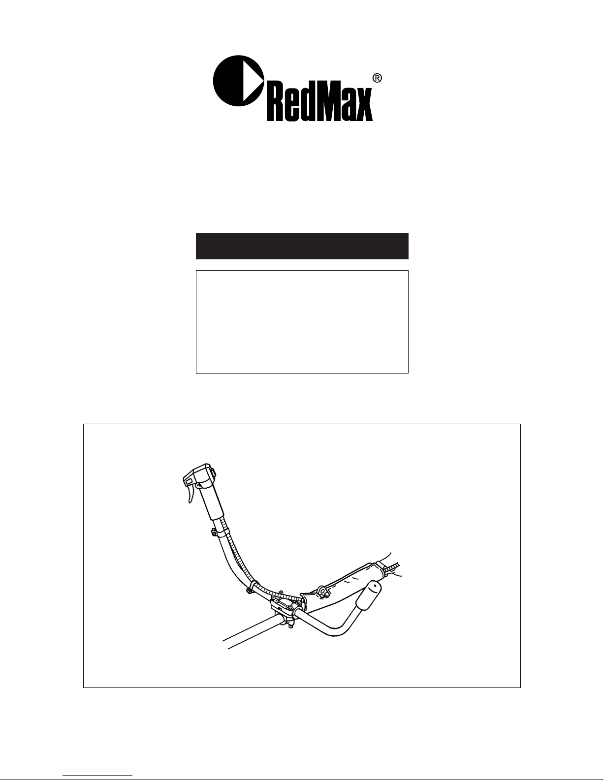
W-HANDLE
KIT
Page 2
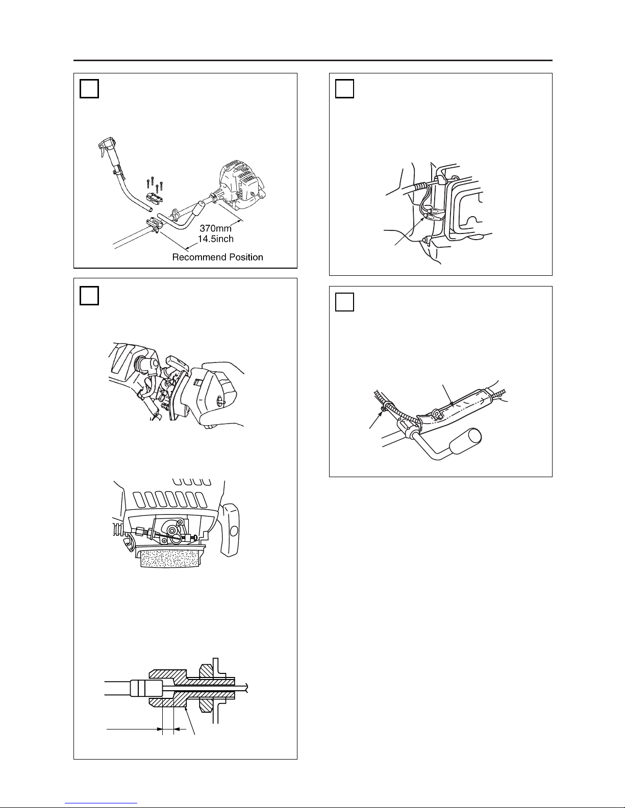
Waist Pad
Band
Switch Wires
Manual For W-HANDLE Kit
• Wrap the waist pad around the shaft
tube and the throttle wire.
PUTTING ON WAIST PAD
• Connect the switch wires between the
engine and the main unit. Pair the
wires of the same color
CONNECTING SWITCH WIRES
CONNECTING THROTTLE WIRE
TO THE CARBURETOR
ADJUSTING THROTTLE CABLE
• The normal play is 1 or 2mm when
measured at the carburetor side end.
Readjust with the cable adjuster as
required.
2. Connect the end of the throttle wire to
the joint on the top of the carburetor.
1. Remove the air cleaner cover.
Mount the handle to the shaft tube and
clamp it at your best operating position.
.04 in
(1~2mm)
Cable Adjuster
1
2
3
4
Page 3

Key# Description Part Number Q'ty
1 HANDLE-L-COMP T3040-14200 1
2 HANDLE-R-COMP T3002-95400 1
3 LEVER-ASSY 6234-14601 1
4 CORD(A) BLACK T3002-95710 1
5 CORD(B) RED T3002-95720 1
6 CABLE-COMP T3040-83100 1
7 TUBE 5512-73220 1
8 CLAMP 3260-14251 1
9 SCREW 0260-00516 1
10 BRACKET-ASSY 3583-14101 1
11 • BRACKET 3583-14111 1
12 • CAP-L 3583-14121 1
13 • CAP-U 3257-14192 1
14 • BOLT 01252-30522 2
15 • BOLT 01252-30525 4
16 PROTECTOR 848-B81-38A1 1
17 BAND 3540-93120 1
Key# Description Part Number Q'ty
Parts List
Page 4

©Printed in Japan
ZENOAH AMERICA, INC.
1100 Laval Blvd. Suite 110
Lawrenceville, Georgia 30043
 Loading...