

Page 1
115 34 40-10 (002)
OWNER’S MANUAL
POWER SPRAYER
NS2522
G
G
B
B
NS2522
Original Language
GB-1
Page 2
NS2522
EC DECLARATION OF CONFORMITY
(Applies to Europe only)
The undersigned manufacturer,
Husqvarna Zenoah Co.,Ltd.,
1-9, Minamidai, Kawagoe, Saitama, Japan,
declares under sole responsibility that the following products referred to in this
declaration conform with the requirement of the following COUNCIL’S DIRECTIVE.
The products referred to are :
DESIGNATION : Power sprayer
MANUFACTURER : Husqvarna Zenoah Co., Ltd.
MODELS : NS2522
SERIAL NUMBERS DATING : 2010 and onwards
(The year is cleary stated on the rating plate,
follwed by the serial number)
This declaration conform with :
・DIRECTIVE 2006/42/EC
(The following standards have been applied: ISO 12100-1,-2, FprEN 15503: 2009)
・DIRECTIVE 2004/108/EC
(The following standards have been applied: EN 61000-6-1, EN 55012 (CISPR 12: 2005))
・DIRECTIVE 2000/14/EC
conformity assessment procedure followed ANNEX V
・DIRECTIVE 2002/88/EC
Date :
Signature :
Kiyoshi Honda
General Manager, Development Center
Authorised representative :
Person authorised to compile the technical file :
29 December 2009
Husqvarna AB
SE-561 82 Huskvarna, Sweden
Bo R Jonsson
SE-561 82 Huskvarna, Sweden
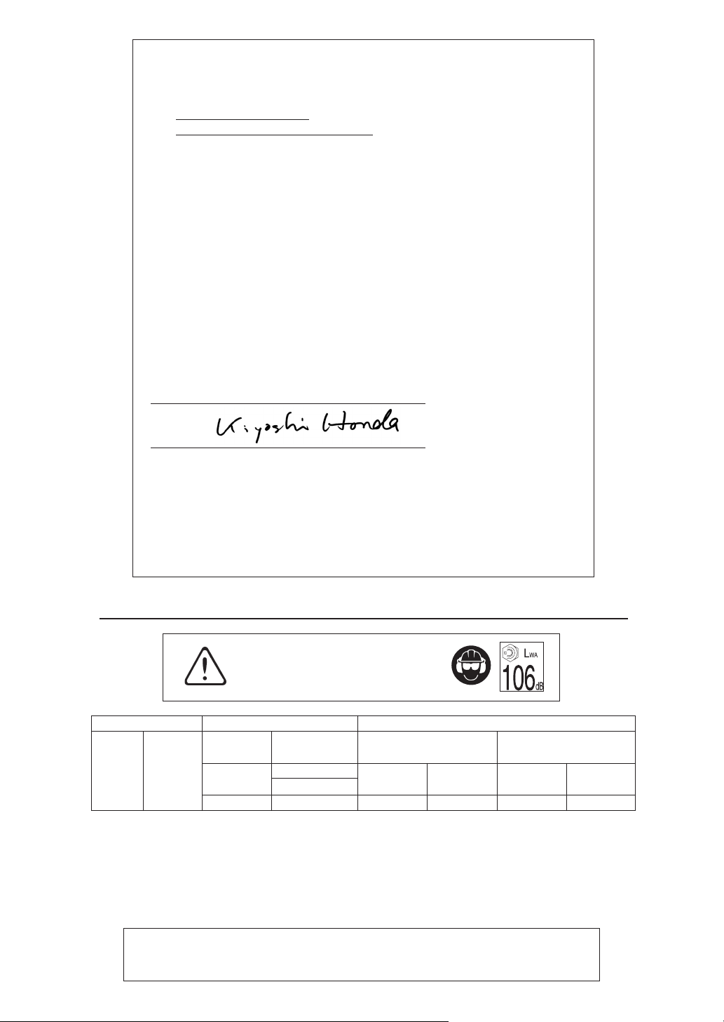
EXPLANATION OF SYMBOLS AND SAFETY WARNINGS
WARNING!!!
RISK OF DAMAGING HEARING
Wear head, eye and ear protection.
MODEL SOUND LEVEL
ISO 11201 ISO 8662-1
NS2522 21.7 cm
3
L
pAav
88 dB(A) 106 dB(A) 0.2 m/s
* Specifications are subject to change without notice
1) Noise emissions in the environment measured as sound power (L
Reported soundpower level for the machine has been measured with the original attachment that gives the highest level.
The difference between guaranteed and measured sound power is that the guaranteed sound power also includes dispersion in the measurement result and the variations between different machines of the same model according to Directive
2000/14/EC.
Reported data for equivalent sound pressure level (L
dispersion (standard deviation) of 1 dB (A).
2) Reported data for equivalent vibration level (a
of 1 m/s
2
.
1)
VIBRATION LEVEL
2000/14/EC
ISO 3744
L
wA
guaranteed
hv,eq) at the control handle has a typical statistical dispersion (standard deviation)
idling
2
WA) in conformity with EC directive 2000/14/EC.
pAeq) at the operator’s ear for the machine has a typical statistical
2.6 m/s
2
2)
2002/44/EC
ISO 22867
ahv, eqracing A(8)
7.3 m/s2 2.6 m/s
2
GB-2
APPROVAL NUMBER OF CE EXHAUST EMISSION REGULATION
DIRECTIVE 97/68/EC AMENDED 2002/88/EC
e13✱97/68SH2G3✱2002/88✱0109✱02
Page 3
NS2522
2
3
5
1
SAFETY PRECAUTIONS
Warning labels bearing the mark on the product and in this
Manual refer to important safety matters. Please familiarize yourself with them and observe them well.
If a warning label on the product becomes soiled or detached,
please order a replacement label from your dealer and attach it
in the requisite place.
PRECAUTIONS
In this Operator's Manual, precautions that are considered to be
particularly important are indicated as follows.
WARNINGS IN THE MANUAL
WARNING
Failure to observe the precaution may result in the risk of death
or serious injury.
IMPORTANT
Failure to observe the precaution may result in damage or malfunction of the product.
NOTE
Other additional explanations that may be of use when operating the product.
Contents
1. Parts location ................................................. 3
2. Specification .................................................. 4
3. Symbols in the manual ................................... 4
4. Symbols on the machine................................ 4
5. For safe operation .......................................... 5
6. Set up ............................................................. 8
7. Fuel .............................................................. 10
8. Chemical filling............................................. 11
9. Operation ..................................................... 11
10. Maintenance ................................................ 12
11. Storage......................................................... 15
12. Troubleshooting guide ................................. 15
13. Disposal ....................................................... 16
G
B
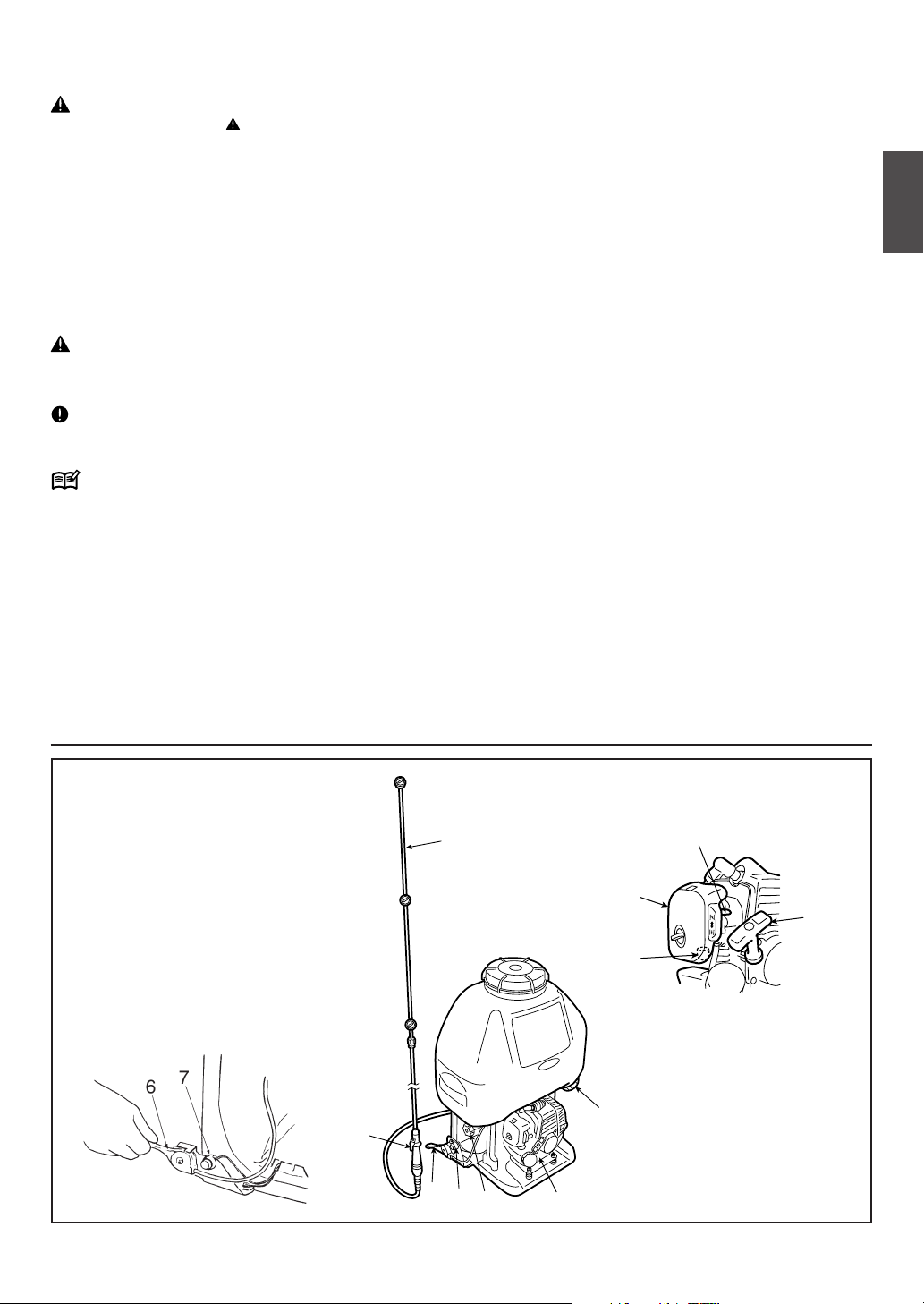
1. Parts location
(1) Primer
(2) Air cleaner cover
(3) Choke lever
(4) Fuel tank
(5) Starter knob
(6) Throttle lever
(7) Stop switch
(8) Spray rod
(9) Grip
(10) Pressure regulating dial
(11) Fluid drain cap
8
11
9
6
7
10
4
GB-3
Page 4
NS2522
2. Specification
Model name and number Zenoah Back-Packed Motorized Sprayer
NS2522
Purpose Spraying agricultural chemicals and cold water
for pest control, weeding, and growth control
Dry weight ∗ (kg) 8.7
External dimensions of main unit
(length x width x height) ∗∗ (mm) 320x470x630
Capacity of chemical fluid tank (litres) 25
Capacity of fuel tank (litres) 0.47
Pump Type Double parallel piston pump
Speed (rpm) 1800
Spray output Normal (MPa) 2.0
Maximum (MPa) 2.5
Maximum water absorption (litres/min) 9
Motor transmission system Centrifugal clutch
Engine Type Single-cylinder air-cooled 2-cycle gasoline engine
Model number Zenoah G20LS
Exhaust capacity (cc) 21.7
Fuel used Lubricating oil/gasoline mix
Lubricating oil used 2-cycle engine oil
Admixture ratio Gasoline 50 : Oil 1 (when using ZENOAH genuine oil)
Carburetor Diaphragm, rotary valve type
Ignition system Electronic controlled flywheel magnet type
Spark plugs NGK BPMR7A
Starter system Recoil starter type
Stopping system Primary cable short circuit
Air cleaner Dry type
Standard accessories 1 spray rod, 1 rod, 1 cock, 1 grip, 1 joint,
1 hose, 1 mix tank, 1 plug wrench
∗ When nozzle (supplied) is attached.
∗∗ Nozzle and back belt are not included.
Due to product improvements, these specifications are subject to change without notice.
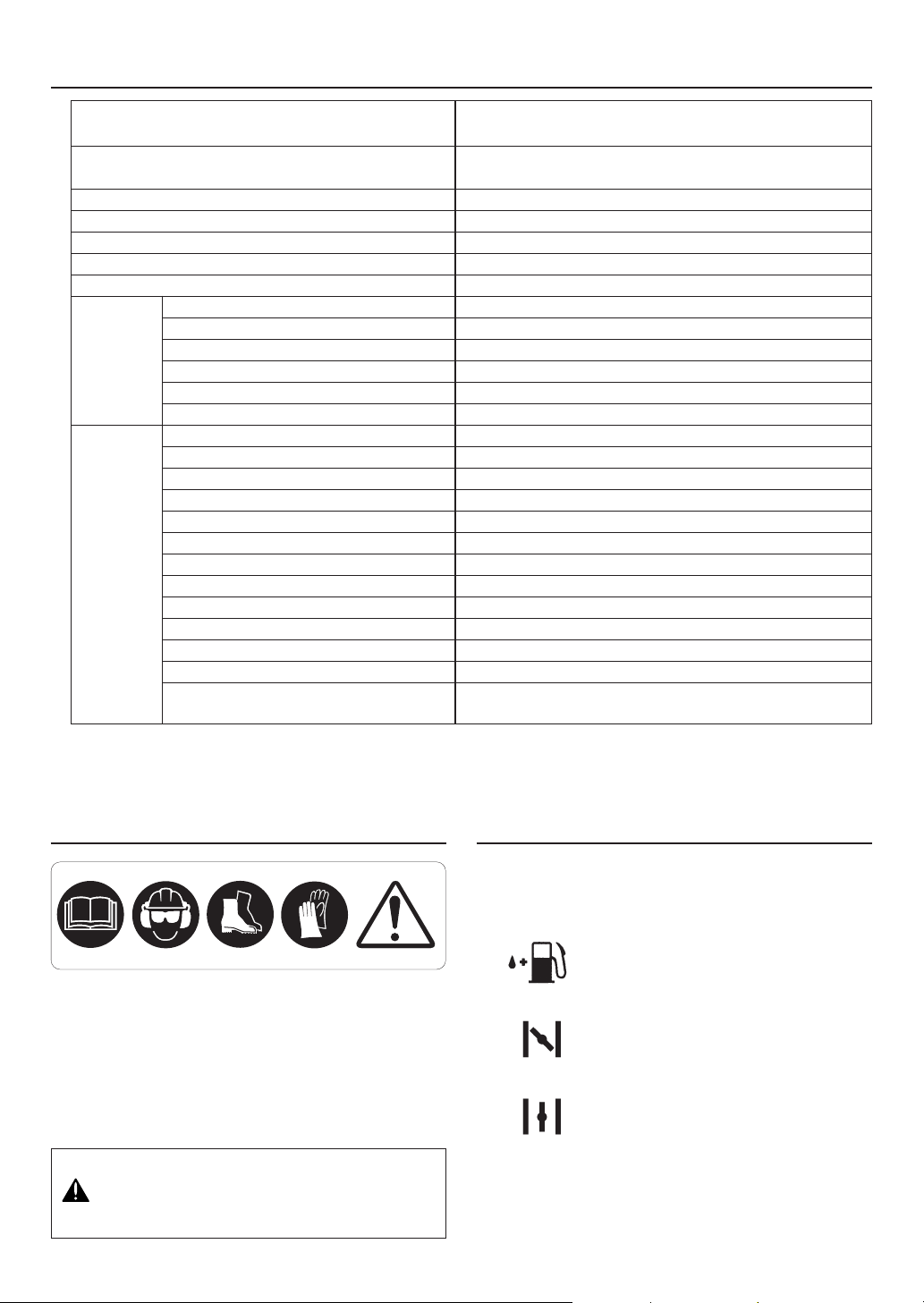
3. Symbols in the manual
(1) (2) (4) (5)
(1) Read owner’s manual before operating this
machine.
(2) Wear head, eye and ear protection.
(3) Wear foot protection.
(4) Wear gloves.
(5) Warning / Attention
Never modify your machine.
We won’t warrant the machine, if you use the
remodeled power sprayer or if you don’t observe
the proper usage written in the manual.
GB-4
(3)
4. Symbols on the machine
For safe operation and maintenance, symbols are carved
in relief on the machine. According to these indications,
please be careful not to make a mistake.
The port to refuel the “MIX GASOLINE”
Position: FUEL TANK CAP
The direction to close the choke
Position: AIR CLEANER COVER
The direction to open the choke
Position: AIR CLEANER COVER
Page 5
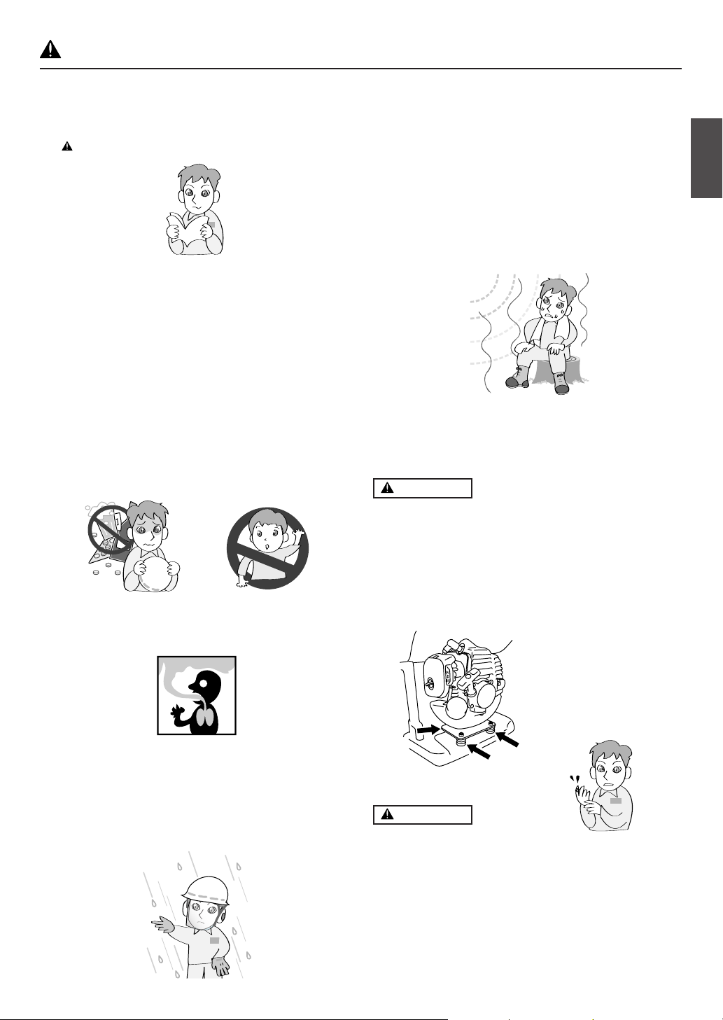
5. For safe operation
NS2522
Before using this product, please read this Operator's
Manual thoroughly to ensure correct operation. The following are precautions that should be observed in order
to use the product smoothly. Elsewhere in the Manual,
the warning mark is used to bring your attention to
these precautions.
BEFORE USING THE PRODUCT
• This product has been designed mainly for the pur-
pose of spraying pest control chemicals and
weedkillers. Please do not use it for any other purpose, as this may cause unforeseen accidents.
• Since this product uses agricultural chemicals that
require careful operation, misuse can be dangerous.
Do not use this product when tired or otherwise in
poor physical condition, or when you may be unable
to judge correctly or operate accurately, such as after
taking cold relief medicines or drinking alcohol. Also,
children or persons who are unable to understand the
contents of this Manual should under no circumstances be permitted to use the product.
• When using for the first time, before commencing
actual spraying please receive guidance in operating the product from a person with adequate experience.
• Fatigue reduces powers of concentration and increases the risk
of accidents. When planning work, please allow ample
time,
setting a limit of 30-40 minutes for single spraying
sessions and breaks of 10-20 minutes in between.
Also, do not spray for more than 2 hours in any one
day.
• Please take good care of this Operator's Manual and
refer to it for additional information from time to time.
• When selling or lending this product, it should be accompanied by this Operator's Manual.
WARNING
G
B
• The engine exhaust gas contains toxic carbon monoxide. Please do not use the product indoors, in vinyl
houses or tunnels, or in other poorly ventilated places.
• Do not use this product in the following cases.
1. When the product could fall over or in other situations
when it is difficult to hold or operate.
2. After sunset or at other times when eyesight is poor
and the safety of the spraying area is difficult to ascertain.
3. In worsening weather (rain, fog, strong wind, lightning,
etc.)
• Check to see if the shock-absorbing rubber mount
has become cracked or otherwise damaged. Note
that failing to replace this rubber mount when it has
become cracked or damaged may cause the engine
to come loose from its frame during use, thus resulting in possible serious bodily injury.
• If cracked, be sure to replace without delay.
WARNING
1. If you don’t observe the working time, or working
manner, Repetitive Stress Injury (RSI) could occur.
If you feel discomfort, redness and swelling of your
fingers or any other part of your body, see a doctor
before getting worse.
2. To avoid noise complaints, in general, operate product between 8 a.m. and 5 p.m. on weekdays and 9
a.m. to 5 p.m. on weekends.
GB-5
Page 6

NS2522
5. For safe operation
IMPORTANT
Check and follow the local regulations as to sound
level and hours of operations for the product.
PRECAUTIONS BEFORE SPRAYING
• Make sure you have the correct protective clothing,
headgear, rubber gloves and boots, a protective
mask, goggles, a towel, protective cream, etc., to prevent chemicals from coming into contact with your
skin or entering your lungs. When spraying, please
wear this protective gear to prevent any risk of injury.
1. Protective headgear
2. Protective goggles
3. Protective mask
4. Rubber boots
5. Ear muffs
6. Neck covering
7. Protective clothing
8. Rubber gloves
9. Protective clothing
• Please store chemicals in a locked storage box, locker,
or other safe place out of the reach of children.
• Carefully read the instructions for using the chemicals, and familiarize yourself with the level of toxicity,
method of use, etc.
• Please pay all due consideration to the area in which
you will be spraying, to ensure that you do not pollute
the water supply, rivers, lakes, ponds, etc., or cause
any damage to residents, passers-by, livestock, etc.
•Prepare yourself physically on the day before spraying, by for example cutting down on alcoholic beverages or late-night work.
• Do not allow children, animals, etc., to enter the
chemical spraying area.
PRECAUTIONS WHEN TRANSPORTING THE
SPRAYER
• Do not transport the sprayer while it has chemicals or
fuel in the tank, as these could leak out as a result of
impact during transportation.
• When transporting in a vehicle, please use a rope or
similar to fix the sprayer firmly to the cargo trailer in
an upright position. Please do not transport by bicycle
or motorbike, as this is dangerous.
PRECAUTIONS CONCERNING FUEL
• The engine of this product is fueled by "mixed gasoline" that includes highly combustible fuel. Do not refuel or store fuel containers where there is any risk of
combustion from incinerators, burners, bonfires,
kitchen stoves, electric sparks, welding sparks, etc.
• Smoking while spraying or refueling is dangerous.
Please avoid this at all costs.
• When refueling during use, always stop the engine
and make sure there are no naked flames in the vicinity before refilling.
• Any fuel spilt during refueling should be wiped off completely with a rag or similar before starting the engine.
• After refueling, seal the fuel container, tightly close the fuel
tank cap, and start the engine at least 3 meters away.
PRECAUTIONS WHEN REFILLING CHEMICALS
• Before filling the tank with chemicals, please make
sure that the spray lever is completely at rest.
• After chemical refilling, firmly tighten the tank cap. If
not fully tightened the cap may become loose during
spraying, with the risk of physical exposure to the
chemicals.
• Before spraying, please prepare fully by inspecting
sprayer nozzles and checking for abnormalities such
as loose screws or spray hose connections, fuel leaks,
defective or broken fluid gaskets, or damage to the
carrying band.
PRECAUTIONS WHEN TRANSPORTING CHEMICALS
• When transporting chemicals, please handle with care
to ensure that there is no spillage of chemicals from
torn bags, broken bottles, or loose stoppers.
• Do not carry chemicals in the same container as food.
GB-6
PRECAUTION WHEN STARTING THE ENGINE
• Please keep children, animals, etc. well away when
starting the engine and spraying.
PRECAUTIONS WHEN SPRAYING
• Since protective clothing generally offers poor ventilation and thus places stress on the body, there is a
risk of contracting heatstroke or other illness when
operating for long periods under high temperatures.
Please avoid spraying on hot days, aiming instead
for early morning and late afternoon times when temperatures are relatively cool and winds are low.
• When starting work, please pay all due consideration
to the spraying time, wind direction, etc., to ensure
that no noise disturbance or chemical hazard is
caused to nearby residents, passers-by, farm crops,
and so on.
• While spraying please hold the grip firmly at all times
and be careful not to point the nozzle in the direction
of people or animals.
Page 7

5. For safe operation
NS2522
• While spraying please be careful of the wind direction and always stand on the upwind side, to avoid
spraying yourself with chemicals.
• Should you begin to feel even
slightly unwell while spraying, consult a doctor immediately. When doing so, inform the doctor of the name
of the chemical you were using, the conditions of use,
etc.
•If the sprayer is tilted the chemical may leak out
through the air holes in the cap. When spraying always make sure you have a firm footing and maintain
your balance.
• Do not touch the spark plugs or plug cords while the
engine is running, as you may get an electric shock.
• Do not touch the muffler, spark plugs, or other metal
parts with your bare hands while the engine is running or immediately after stopping the engine, as there
is the risk of burns due to high temperatures.
work, duration of the work, and other details.
• Please keep the following points in mind when selecting or using protective gear.
a) Protective clothing
Choose clothing that is cool to wear and offers good
ventilation and waterproofing. In addition, wear items
that enable you to carry out spraying work in total
comfort and safety.
b) Spraying hood
Use a hood with a brim that is waterproof and covers
your neck and shoulders.
c) Gloves
Use gloves that are difficult for chemicals to penetrate
and do not slip even if you perspire while doing the
work.
d) Rubber apron
When mixing chemicals, wear a long, thick, and wide
apron that cannot be penetrated by chemical
splashes.
e) Protective goggles, mask, etc.
Select suitable protective goggles, mask, rubber
boots, eye washer, and protective cream, etc., paying attention to standards and the recommendations
of farm work safety promotion organizations.
G
B
PRECAUTIONS AFTER SPRAYING
• Please seal unused chemicals and store them out of
the reach of children.
• Do not simply discard empty chemical containers, but
dispose of them safely by incinerating, burying, or
another similar method. In addition, please take every care that the water used to clean spraying tools
does not create any hazard.
• Fully inspect and maintain protective clothing, masks,
gloves, and other protective gear in preparation for
the next session.
• After completing the work and tidying away chemicals and spraying tools, you should immediately take
a bath or wash your hands, feet, face, etc. thoroughly
with soap, as well as washing your mouth out.
•You should change all clothes worn, including underwear, and wash them thoroughly. Clothes worn during spraying should not be worn again the following
day.
• After spraying, please limit your alcohol intake and
rest thoroughly by going to bed early. If you feel even
slightly unwell, please see a doctor as soon as
possible.
OTHER PRECAUTIONS
• When engaged in spraying work over a protracted
period of time, please have your health checked regularly.
• Please carry out spraying in a planned fashion, keeping a daily record of the date and time of spraying,
the chemicals used, the target pest, contents of the
MAINTENANCE PRECAUTIONS
• In order to maintain the functions of the product, regularly carry out the maintenance inspections listed in
this Manual. When maintenance or parts replacement
not indicated in this Manual are required, please consult your product supplier or nearest ZENOAH product dealer.
• Never keep the engine running while carrying out inspections or maintenance.
• Do not modify the sprayer or dismantle the engine.
This could lead to breakdown and serious accidents
during operation.
• Do not touch the muffler or spark plugs with your bare
hands immediately after stopping the engine. There
is the risk of burns due to high temperature.
• For replacement parts, please use original ZENOAH
parts or brands designated by ZENOAH.
MAINTENANCE OF LABELS
1. Please keep warning labels clean and unmarked.
2. If warning labels become soiled or peel off, please
order from your supplier and replace with new ones.
3. When affixing new labels please wipe off all dirt and
moisture.
GB-7
Page 8

NS2522
6. Set up
A Package contains the items as illustrated.
1
7
3
6
4
5
2
9
8
10
(1) Unit
(2) Spray rod
(3) Cock
(4) Grip
(5) Joint
(6) Spray hose
(7) Rod
(8) Plug wrench (S13/S19) with phillips screw driver
(9) Mix tank
(10) Owner’s manual
GB-8
Page 9

6. Set up
a
b
c
NS2522
■ Connecting the spray hose and nozzle
h
f
g
e
a. spray rod
b. cock
c. grip
d. joint
e. spray hose
f. connecting nut
g. spray outlet
h. rod
a
b
c
d
1. Connect the spray hose to the pump spray outlet and
firmly tighten the connecting nut.
2. Tightly screw the joint onto the hose.
3. Tightly screw the grip onto the joint.
4. Tightly screw the cock onto the grip.
5. Tightly screw the rod onto the cock.
6. Tightly screw the spray rod onto the rod.
■ Adjusting spray pressure
• NS2522 has a pressure regulating dial to change
spray pressure. Set the pressure at a level appropriate to the spray conditions.
Set the pressure regulating dial as follows:
•Turn in a clockwise direction to increase the pressure.
•Turn in a counterclockwise direction to decrease the
pressure.
a. Pressure regulating dial
b. Decreasing the pressure
c. Increasing the pressure
G
B
GB-9
Page 10

NS2522
7. Fuel
■ FUEL
WARNING
• Gasoline is very flammable. Avoid smoking or
bringing any flame or sparks near fuel. Make sure
to stop the engine and allow it cool before refueling the unit. Select outdoor bare ground for fueling and move at least 3 m (10 ft) away from the
fueling point before starting the engine.
• The Zenoah engines are lubricated by oil specially
formulated for air-cooled 2-cycle gasoline engine use.
If Zenoah oil is not available, use an anti-oxidant added
quality oil expressly labeled for air-cooled 2-cycle
engine use (JASO FC GRADE OIL or ISO EGC
GRADE).
• Do not use BIA or TCW (2-stroke water-cooling type)
mixed oil.
■ RECOMMENDED MIXING RATIO
GASOLINE 50 : OIL 1
(when using ZENOAH genuine oil)
• Exhaust emission are controlled by the fundamental engine parameters and components (eq.,
carburation, ignition timing and port timing) without addition of any major hardware or the introduction of an inert material during combustion.
• These engines are certified to operate on unleaded
gasoline.
• Make sure to use gasoline with a minimum octane
number of 89RON (USA/Canada: 87AL).
• If you use a gasoline of a lower octane value than
prescribed, there is a danger that the engine temperature may rise and an engine problem such as
piston seizing may consequently occur.
• Unleaded gasoline is recommended to reduce the
contamination of the air for the sake of your health
and the environment.
•Poor quality gasolines or oils may damage sealing
rings, fuel lines or fuel tank of the engine.
■ HOW TO MIX FUEL
WARNING
4. Pour in the rest of gasoline and agitate again for at
least one minute. As some oils may be difficult to agitate depending on oil ingredients, sufficient agitation
is necessary for the engine to last long. Be careful
that, if the agitation is insufficient, there is an increased
danger of early piston seizing due to abnormally lean
mixture.
5. Put a clear indication on the outside of the container
to avoid mixing up with gasoline or other containers.
6. Indicate the contents on outside of container for easy
identification.
■ FUELING THE UNIT
1. Untwist and remove the fuel cap. Rest the cap on a
dustless place.
2. Put fuel into the fuel tank to 80% of the full capacity.
3. Fasten the fuel cap securely and wipe up any fuel
spillage around the unit.
WARNING
1. Select bare ground for fueling.
2. Move at least 3 meters (10 feet ) away from the fueling point before starting the engine.
3. Stop the engine before refueling the unit. At that time,
be sure to sufficiently agitate the mixed gasoline in
the container.
■ FOR YOUR ENGINE LIFE, AVOID:
1. FUEL WITH NO OIL (RAW GASOLINE) – It will cause
severe damage to the internal engine parts very
quickly.
2. GASOHOL – It can cause deterioration of rubber and/
or plastic parts and disruption of engine lubrication.
3. OIL FOR 4-CYCLE ENGINE USE – It can cause spark
plug fouling, exhaust port blocking, or piston ring sticking.
4. Mixed fuels which have been left unused for a period
of one month or more may clog the carburetor and
result in the engine failing to operate properly.
5. In the case of storing the product for a long period of
time, clean the fuel tank after rendering it empty. Next,
activate the engine and empty the carburetor of the
composite fuel.
6. In the case of scrapping the used mixed oil container,
scrap it only at an authorized repository site.
NOTE
• As for details of quality assurance, read the description in the section Limited Warranty carefully. Moreover, normal wear and change in product with no functional influence are not covered by the warranty. Also,
be careful that, if the usage in the instruction manual
is not observed as to the mixed gasoline, etc. described therein, it may not be covered by the warranty.
• Pay attention to agitation.
1. Measure out the quantities of gasoline and oil to be
mixed.
2. Put some of the gasoline into a clean, approved fuel
container.
3. Pour in all of the oil and agitate well.
GB-10
Page 11

8. Chemical filling
WARNING
• Chemical substances should be handled correctly,
observing the precautions marked on the container.
Some chemicals are extremely hazardous to humans
and animals, and handling errors can cause serious
poisoning or even fatal accidents.
• When not in use, chemical substance containers
should be stored separately from other containers out
of the reach of children.
IMPORTANT
• Do not fill the chemical tank with undiluted fluid. This
could cause the gasket and valves to lose their durability.
9. Operation
NS2522
■ Procedure for filling
1. Use a bucket or other suitable container and dilute
the chemical to the requisite strength.
2. Place the sprayer on an even and stable surface and
remove the chemical tank cap.
3. Fill the tank by passing chemical through the strainer.
4. When filling is complete, firmly tighten the cap.
a. strainer
Chemical tank capacity: 25 litres
G
B
WARNING
• Highly combustible. When refueling, switch the engine off and keep well away from naked flames.
• After filling the tank with fuel, firmly tighten the
cap.
a. cap
b. fuel tank
a
■ Starting engine
WARNING
• Before starting the engine, make sure that the spray
lever (spray valve) is completely returned. Starting with
the spray lever still pulled out is dangerous, as chemical fluid may spray out of the nozzle as soon as the
engine is started.
b
1. Press the primer at the bottom of the carburetor a few
times with your finger until the fuel starts to flow through
the transparent pipe.
a. air cleaner
b. choke lever
c. close
d. open
e. transparent pipe
f. primer
NOTE
• There is no need to operate the primer when restarting immediately after stopping the engine, provided
there is fuel left in the fuel tank.
2. Lift the choke lever on the right of the air cleaner until
it is in the "closed" position, then open the throttle lever on the main unit side about 1/3-1/2 from the "slow"
position.
g. throttle lever
h. fast
i. slow
•To start the engine, place the sprayer on an even and
stable surface or platform. If the sprayer is unstable,
the reaction on starting etc. may cause it to fall.
IMPORTANT
• Do not allow the chemical fluid or water in the tank to
run out while the engine is running. If the engine runs
empty it may cause breakage of the spray pump.
NOTE
• When restarting immediately after stopping the engine, set the choke lever to "open" and the throttle
lever to "slow".
GB-11
Page 12

NS2522
9. Operation
3. Place the sprayer in a stable location, and pull the
starter knob with the right hand while holding the
chemical tank down with the left hand. The starter knob
should first be pulled out lightly, then, when resistance
is felt, pulled more swiftly and vigorously.
IMPORTANT
• Do not pull the rope out completely or release the knob
so that the rope returns, as this can cause starter malfunction.
4. Once the engine has started, gradually open the
choke, warm up at low speed for 1-2 minutes, then
return the throttle lever to the "slow" position.
IMPORTANT
• If the rope is pulled continuously with the choke
closed, the spark plugs may become flooded and the
engine may fail to start. If so, you should first remove
the spark plugs and dry the electrodes, then repeat
the starting procedure.
■ Stopping engine
WARNING
• Stop the engine immediately in the event of an emergency.
1. Lower the throttle lever fully and cool the engine down
for 1-2 minutes at low speed.
2. Hold down stop switch on the left side of the sprayer
frame until the engine has come to a complete stop .
a. Stop switch
■ Spraying
WARNING
• Please use correctly, observing the precautions in this
Manual ("For Safe Operation", p5 to 7).
• Before lifting the sprayer onto your back, check that
the chemical tank and fuel tank caps are tightly closed.
•When spraying, do not point the nozzle at your face,
or at other people, animals, etc.
• If the sprayer is tilted too much, chemical fluid or fuel
may leak out through the air holes in the cap. When
using, always try to maintain an upright posture.
IMPORTANT
• If the chemical tank becomes empty while spraying,
reduce the engine to low speed immediately. Empty
running of the engine may cause the spray pump to
break.
• Please avoid using multiple nozzles, jet nozzles, or
other nozzles that give a large spray volume, as spraying efficiency is sometimes impaired owing to insufficient pressure.
■ Spraying procedure
1. Start the engine, and lift the sprayer onto your back.
2. Adjust the carrying band to a suitable length for carrying.
3. Increase the engine speed, and open the spray cock.
Chemical fluid starts to spray out from the nozzle in
the form of mist.
4. When stopping work, close the spray cock fully and
reduce the engine speed.
b
c
a
b
■ Cleaning after completion of spraying
1. Loosen the fluid drain cap , transfer the chemical fluid
left inside the tank into a suitable container, and process appropriately with all due consideration to safety.
2. Pour about 5 litres of clean water into the chemical
tank, spray through the nozzle for 2-3 minutes, and
drain the water left inside the tank.
a. Spray cock
b. Close
c. Open
IMPORTANT
• Except for an emergency, avoid stopping the engine
while pulling the throttle trigger.
GB-12
a. Fluid drain cap
Page 13

10. Maintenance
Every Every Every
System/components Procedure
fuel leaks, fuel spillage wipe out ✔
fuel tank, air filter, fuel filter inspect/clean ✔✔ replace, if necessary
idle speed adjuster ✔
spark plug ✔
ENGINE
intake air cooling vent clean ✔
throttle lever, stop switch check operation ✔
screws/nuts/bolts tighten/replace ✔✔except adjusting screws
WARNING
• Make sure that the engine has stopped and is cool
before performing any service to the machine. Contact with hot muffler may result in a personal injury.
• Do not modify the sprayer or dismantle the engine.
• When replacing parts please use Zenoah original
parts or designated parts.
see adjusting replace carburetor
idling speed if necessary
clean and readjust GAP: 0.6 to 0.7 mm (.025 in)
plug gap replace, if necessary
Before
use
25 50 100
hours hours hours
after after after
■ Fuel filter
After every 25 hours of operation, empty the fuel tank,
detach the fuel filter from the tank, and remove all dirt. If
the filter is too clogged, please replace it with a new
one.
Note
NS2522
G
B
■ Air cleaner
• After every 25 hours of operation, please remove the
air cleaner cover and inspect the element. If it is too
dirty, wash it carefully in warm water containing a neutral detergent, and return it to its original position after drying it thoroughly.
• If the element is distorted or damaged, please replace
it with a new one.
a. Element
b. Air cleaner cover
IMPORTANT
• If the air cleaner element is blocked, the efficiency of
the engine will be reduced. In addition, the engine
interior will suffer abnormal wear if operated without
the element or if continually operated with a distorted
or damaged element fitted.
a. Fuel filter
IMPORTANT
• If the fuel filter is clogged, the engine speed may be
limited or speed fluctuations may occur.
• If the engine is operated without a fuel filter, dirt will
accumulate in the carburetor and cause it to malfunction.
■ Spark plug
WARNING
• Do not touch the spark plug with your bare hands
immediately after operation, as there is the risk of
burns due to high temperature.
• After every 50 hours of operation, detach the spark
plug and remove dirt from the electrodes with a wire
brush or similar.
• The correct electrode gap is 0.6 to 0.7mm.
GB-13
Page 14

NS2522
10. Maintenance
• When replacing plugs, please use designated items.
NGK (BPMR7A)
IMPORTANT
• If too much fuel is absorbed or poor quality oil is used,
the spark plug electrodes become dirty, making the
engine harder to start.
• Note that using any spark plug other than those designated may result in the engine failing to operate
properly or in the engine becoming overheated and
damaged.
•To install the spark plug, first turn the plug until it is
finger tight, then tighten it a quarter turn more with a
socket wrench.
TIGHTENING TORQUE:
14.7 to 21.6 N.m.
(150 to 220 kgf-cm)
■ Adjusting the engine
Although the engine is adjusted on leaving the factory,
after repeated use it may sometimes require readjustment or maintenance. Please consult your original supplier regarding inspections and maintenance other than
those shown below.
NOTE
•Warm up the engine before adjusting the idling speed.
• Throttle wire play
Throttle wire play should be 1 to 2 mm. After completely returning the throttle lever, take the throttle wire
at the carburetor end in your fingers and give a light
tug. If the play is too great or too small, readjust the
position of the wire retaining nut. Loosen the lock nut
and turn the wire retaining nut clockwise (screw in) to
increase the play and counter-clockwise (unscrew)
to reduce it. After adjusting, please fasten the wire
retaining nut by tightening the lock nut.
a. lock nut
b. wire retaining nut
c. wire sleeve
MUFFLER
WARNING
• Idling speed
If the engine stalls or the pump continues to move
when in idling position with the throttle lever completely
lowered, readjust the engine speed using the idle
speed adjuster on the left of the carburetor.
a. idle speed adjuster
b. increase speed
c. reduce speed
•Turn the idling adjustment screw:
— counter-clockwise to reduce engine speed
— clockwise to increase engine speed
• Inspect periodically, the muffler for loose fasteners, any damage or corrosion. If any sign of exhaust leakage is found, stop using the machine
and have it repaired immediately in the repair specialty store.
• Note that failing to do so may result in the engine
catching on fire.
INTAKE AIR COOLING VENT
WARNING
• Check the intake air cooling vent after every 25
hours of use for blockage.
■ PERIODICAL SERVICE POINTS
1. CYLINDER FINS
Periodically check and clean the cylinder fins in the repair specialty store.
IMPORTANT
• If waste gets stuck and causes blockage around the
intake air cooling vent, it may cause the engine to overheat, and that in turn may cause mechanical failure
GB-14
Page 15

10. Maintenance
on the part of the brushcutter.
(1) Intake air cooling vent
11. Storage
WARNING
• When draining fuel, please be careful not to spill it. If
fuel is spilt, wipe off thoroughly. In addition, please be
sure to close the storage container cap tightly.
IMPORTANT
• If fuel is left in the engine for protracted periods, the
inside of the carburetor may become clogged and
cause engine malfunction (faulty starting and insufficient output).
• During storage, slightly loosen the cap of the chemical fluid tank. If screwed too tightly, the gasket may
become distorted.
On completion of all work procedures, when not planning to use again for a protracted period please carry
out the following pre-storage care, to prevent trouble
caused by time-lapse changes.
NS2522
G
B
1. Clean the chemical fluid tank and nozzle (see page
11).
2. Remove dirt from the sprayer, inspect it for any damage or looseness, and, if any abnormality is found,
correct it thoroughly in preparation for the next time
you use the unit.
3. Drain the fuel tank.
4. Start the engine, and leave it in idling condition until
all the fuel inside the carburetor is spent and the engine comes to a natural stop.
5. Remove the spark plug and put a few drops (1 to 2
cc) of 2-cycle oil inside the engine. After pulling the
starter rope 2 or 3 times, return the spark plugs to
their original position and stop in compressed position.
6. After oiling the throttle lever and other metal parts with
anti-corrosive oil, cover the sprayer and store indoors
in a low-humidity location.
12. Troubleshooting guide
Case 1. Starting failure
CHECK PROBABLE CAUSES ACTION
fuel tank → incorrect fuel → drain it and use correct fuel
fuel filter → fuel filter is clogged → clean
carburetor adjustment screw → out of normal range → adjust to normal range
sparking (no spark) → spark plug is fouled/wet → clean/dry
→ plug gap is incorrect → correct (GAP: 0.6 to 0.7 mm)
spark plug → disconnected → retighten
Case 2. Engine starts but does not keep running/hard re-starting
CHECK PROBABLE CAUSES ACTION
fuel tank → incorrect fuel or staled fuel → drain it and use correct fuel
carburetor adjustment screw → out of normal range → adjust to normal range
muffler, cylinder (exhaust port) → carbon is built-up → consult with the repair specialty store
air cleaner → clogged with dust → wash
cylinder fin, fan cover → clogged with dust → consult with the repair specialty store
When your unit seems to need further service, please consult with our ZENOAH® service shop in your area.
GB-15
Page 16

NS2522
13. Disposal
• When you dispose of the machine, do not disassemble the machine.
• When you dispose of the machine, fuel, oil, be sure
to follow your local regulations.
Limited warranty
Should any failure occur on the product under normal operating conditions within the applicable warranty period, the
failed part will be replaced or repaired free of charge by a
ZENOAH® authorized dealer.
WARRANTY PERIOD: 1 year (6 months if used professionally, and 30 days if used for rental purpose) from the date of
initial purchase.
THE PURCHASER SHALL BEAR COSTS OF TRANSPORTING THE UNIT TO AND FROM THE ZENOAH DEALER.
THE PURCHASER SHALL NOT BE CHARGED FOR DIAGNOSTIC LABOR WHICH LEADS TO THE DETERMINATION
THAT A WARRANTED PART IS DEFECTIVE, IF THE DIAGNOSTIC WORK IS PERFORMED AT THE ZENOAH DEALER.
THE PURCHASER OR OWNER IS RESPONSIBLE FOR THE
PERFORMANCE OF THE REQUIRED MAINTENANCE AS
DEFINED BY THE MANUFACTURER IN THE OWNER/OPERATOR MANUAL.
ANY WARRANTED PART WHICH IS NOT SCHEDULED FOR
REPLACEMENT AS REQUIRED MAINTENANCE, OR
WHICH IS SCHEDULED ONLY FOR REGULAR INSPECTION
TO THE EFFECT OF REPAIR OR “REPLACE AS NECESSARY” SHALL BE WARRANTED FOR THE WARRANTY PERIOD. ANY WARRANTED PART WHICH IS SCHEDULED
FOR REPLACEMENT AS REQUIRED MAINTENANCE
SHALL BE WARRANTED FOR THE PERIOD OF TIME UP
TO THE FIRST SCHEDULED REPLACEMENT POINT FOR
THE PART.
ANY REPLACEMENT PART THAT IS EQUIVALENT IN PERFORMANCE AND DURABILITY MAY BE USED IN NONWARRANTY MAINTENANCE OR REPAIRS, AND SHALL
NOT REDUCE THE WARRANTY OBLIGATION OF THE
COMPANY.
THE COMPANY IS LIABLE FOR DAMAGES TO OTHER
ENGINE COMPONENTS CAUSED BY THE FAIRURE OF A
WARRANTED PARTS STILL UNDER WARRANTY.
THE WARRANTY DOES NOT APPLY TO THOSE UNITS
WHICH HAVE BEEN DAMAGED BY NEGLIGENCE OF INSTRUCTION LISTED IN THE OWNER/OPERATOR MANUAL
FOR PROPER USE AND MAINTENANCE OF THE UNITS
ACCIDENT MISHANDLING, ALTERATION, ABUSE, IMPROPER LUBRICATION, USE OF ANY PARTS OR ACCESSORIES OTHER THAN THOSE SPECIFIED BY THE COMPANY, OR OTHER CAUSES BEYOND THE COMPANY’S
CONTROL.
THIS WARRANTY DOES NOT COVER THOSE PARTS REPLACED BY NORMAL WEAR OR HARMLESS CHANGES
IN THEIR APPEARANCE.
THERE ARE NO OTHER EXPRESS WARRANTIES.
IMPLIED WARRANTIES INCLUDING THOSE OF MER-
CHANTABILITY AND FITNESS FOR A PARTICULAR PURPOSE ARE LIMITED TO TWO (2) YEARS OF HOME USE
[ONE (1) YEAR FOR ANY OTHER USE] FROM THE ORIGINAL DELIVERY DATE.
LIABILITIES FOR INCIDENTAL OR CONSEQUENTIAL
DAMAGE UNDER ANY AND ALL WARRANTIES ARE
EXCLUDED.
IF YOU NEED TO OBTAIN MORE INFORMATION, PLEASE
CALL YOUR NEAREST SERVICE CENTER,
OR CHECK PLEASE ZENOAH WEB SITE
http://www.zenoah.net
GB-16
 Loading...