

MAXinBOX FC 0-10V VALVE
Two/Four-Pipe Fan Coil Controller
with 0-10 VDC Valve Control Signal
USER MANUAL
ZCL-FC010V
Application Program Version: [1.0]
User Manual Version: [1.0]_a
www.zennio.com

MAXinBOX FC 0-10V VALVE
http://www.zennio.com Technical Support: http://zennioenglish.zendesk.com
2
CONTENTS
Contents ........................................................................................................................................ 2
1 Introduction ............................................................................................................................. 3
1.1 MAXinBOX FC 0-10V VALVE .............................................................................................. 3
1.2 Installation ........................................................................................................................ 4
1.3 Start-up and Power Loss ................................................................................................... 5
2 Configuration ........................................................................................................................... 6
2.1 General ............................................................................................................................. 6
2.2 Inputs ................................................................................................................................ 8
2.3 Individual Binary Outputs ................................................................................................. 9
2.4 Individual 0-10V Analogue Outputs ............................................................................... 10
2.5 Fan Coil ........................................................................................................................... 13
2.5.1 Configuration .......................................................................................................... 13
2.5.1.1 Alarms.............................................................................................................. 19
2.5.1.2 Forced position ................................................................................................ 22
2.5.1.3 Purge ............................................................................................................... 24
2.5.1.4 Scenes .............................................................................................................. 26
2.5.2 Valves ...................................................................................................................... 28
2.5.2.1 Minimum Valve Opening ................................................................................. 32
2.5.3 Fan .......................................................................................................................... 34
2.5.3.1 Delays .............................................................................................................. 40
2.5.3.2 Silent Mode ..................................................................................................... 42
2.5.3.3 Custom start .................................................................................................... 43
2.6 Logic Functions ............................................................................................................... 44
2.7 Thermostats ................................................................................................................... 45
2.8 Manual control ............................................................................................................... 46
Annex I: Fan Coil Priorities .......................................................................................................... 50
Annex II: Communication objects ............................................................................................... 51

MAXinBOX FC 0-10V VALVE
http://www.zennio.com Technical Support: http://zennioenglish.zendesk.com
3
1 INTRODUCTION
1.1 MAXinBOX FC 0-10V VALVE
MAXinBOX FC 0-10V VALVE from Zennio is a versatile KNX multi-function actuator
that aims at fu lfilling the climate control needs of KNX environments with integrated fan
coil units where the valves in the pipes are controlled through analogue 0-10 VDC
signals, while the fan speed needs to be controlled through binary outputs (relays).
The actuator provides two analogue outputs and four binary outputs, which permits
controlling one fan coil drive consisting of two or four pipes (each with its own
valve) and a fan system with up to four speeds.
At a glance, the most outstanding features of MAXinBOX FC 0-10V VALVE are:
1 control module for two-pipe or four-pipe fan coil units with either valves
controlled through a 0-10V DC signal proportional to the opening level, or
valves with their own KNX actuator (remote valve control).
2 analogue 0-10 VDC outputs to control the valves of the fan coil pipes, or
for an independent use.
4 binary (relay) outputs to control up to four fan speeds, or for an
independent use.
4 multi-purpose inputs, each of them configurable as:
Temperature probe,
Binary input (i.e., pushbuttons, switches, sensors),
Motion detector.
10 customisable, multi-operation logic functions.
2 independent thermostats.

MAXinBOX FC 0-10V VALVE
http://www.zennio.com Technical Support: http://zennioenglish.zendesk.com
4
Manual operation / supervision of the relay outputs and the 0-10 VDC
signals through the on-board pushbuttons and LEDs.
1.2 INSTALLATION
MAXinBOX FC 0-10V VALVE connects to the KNX bus through the on-board KNX
connector.
Once the device is provided with power from the KNX bus, both the individual address
and the associated application program may be downloaded.
This device does not need any additional external power, since it is ent irely powered
through the KNX bus.
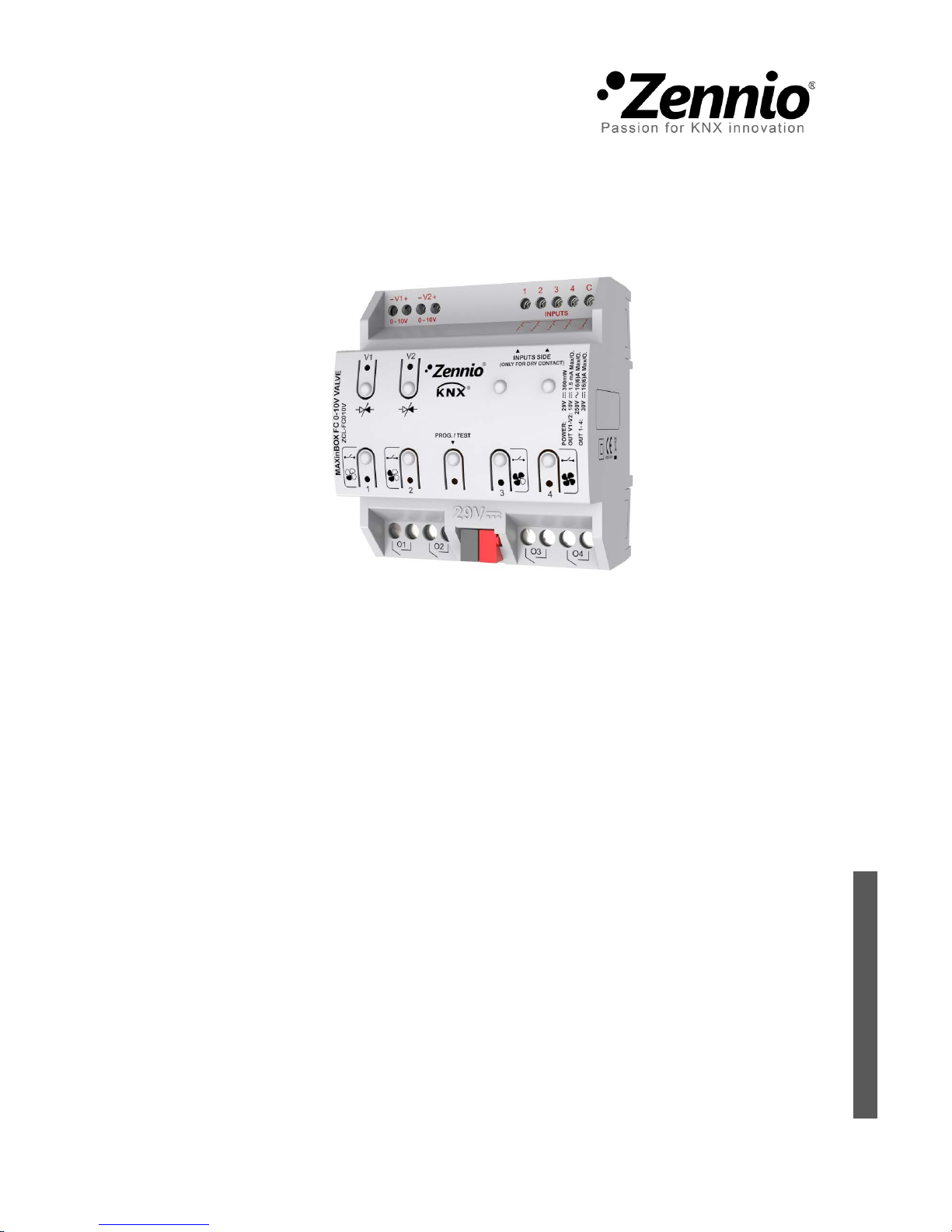
Figure 1 MAXinBOX FC 0-10V VALVE.
The main elements of the device are described next.
Prog./Test pushbutton (8): a short pr ess on this button sets the device into
programming mode, making the associated LED (5) light in red.
Note: if this button is held while plugging the device into the KNX bus, the
device will enter into safe mode. In such case, the LED will blink in red e very
0.5 seconds.
1. Multi-Purpose Inputs.
2. 0-10 VDC Outputs.
3. Output Status LED Indicator.
4. Output Control Button.
5. Prog./Test LED.
6. Binary Outputs.
7. KNX Bus Connector.
8. Prog./Test button.
1
8 3 5
6 2 4

MAXinBOX FC 0-10V VALVE
http://www.zennio.com Technical Support: http://zennioenglish.zendesk.com
5
Outputs (2) and (6): output ports for the insertion of the stripped cables of
the systems being controlled by the actuator (see sections 2.3, 2.4 and 2.5).
Please secure the connection by means of the on-board screws.
For detailed information about the technical features of the device and for safety
instructions and on the installation process, please refer to the Datasheet bundled with
the original packaging of the device and also available at www.zennio.com.
1.3 START-UP AND POWER LOSS
During the start-up of the device, the Prog./Test LED will blink in blue col our for a few
seconds before MAXinBOX FC 0-10V VALVE is ready. External orders will not be
executed during this time, but afterwards.
Depending on the configuration of the fan coil control module, some specific actions
will also be performed during the start-up. For example, the integrator can set whether
the outputs should switch to a particular state and whether the device should send
certain objects to the bus after the power recovery. Please consult the next sections of
this document for further details.
On the other hand, when a bus power failure takes place, MAXinBOX FC 0-10V
VALVE will interrupt any pending actions, and will save its state so it can be recovered
once the power supply is restored. Moreover, all relay outputs will remain open, for
safety reasons.

MAXinBOX FC 0-10V VALVE
http://www.zennio.com Technical Support: http://zennioenglish.zendesk.com
6
2 CONFIGURATION
2.1 GENERAL
ETS PARAMETERISATION
Figure 2 General screen.
After importing the corresponding database in ETS and adding the device into the
topology of the desired project, the configuration process begins by right-clicking into
the device and selecting Edit parameters.
This will bring the window shown in Figure 2. From this screen it is possible to
activate/deactivate all the required functionality through the corresponding checkboxes:
Once activated, Inputs, Binary Outputs, Analogue Outputs, Fan Coil,
Logical Functions, Thermostats and Manual Control (enabled by default)
bring additional tabs to the menu on the left. These functions and their
parameters will be explained in later sections of this document.
Note: when the Fan Coil funct ion gets enabled, the checkboxes to enable the
Binary Outputs and the Analogue Outputs will become locked as these
outputs are required for the fan coil control. Nevertheless, they may become
unlocked again depending on how the fan coil module is configured.
Sending of Indication Objects (0 and 1) on Bus Voltage Recovery: this
parameter lets the integrator activate two new communication objects (“ Reset

MAXinBOX FC 0-10V VALVE
http://www.zennio.com Technical Support: http://zennioenglish.zendesk.com
7
0” and “Reset 1”), which will be sent to the KNX bus with values “0” and “1”
respectively whenever the device begins operation (for example, after a bus
power failure). It is possible to parameterise a certain delay for t his sending
(0 to 255 seconds).

MAXinBOX FC 0-10V VALVE
http://www.zennio.com Technical Support: http://zennioenglish.zendesk.com
8
2.2 INPUTS
MAXinBOX FC 0-10V VALVE incorporates 2 analogue/digital inputs, each configurable
as a:
Binary Input, for the connection of a pushbutton or a switch/sensor.
Temperature Probe, to connect a temperature sensor as models
ZN1ACNTC68 S/E/F and ZN1AC-SQAT (SQ-AmbienT) from Zennio.
Motion Detector, to connect a motion detector (models ZN1IO-DETEC-P
and ZN1IO-DETEC-X from Zennio).
For detailed information about the functionality and the configuration of the parameters
involved, please refer to the following specific manuals, available under the
MAXinBOX FC 0-10V VALVE product section, at the Zennio homepage,
www.zennio.com):
“Binary Inputs in MAXinBOX FC 0-10V VALVE”,
“Temperature Sensor in MAXinBOX FC 0-10V VALVE”,
“Motion Detector in MAXinBOX FC 0-10V VALVE”.
Notes:
The ZN1IO-DETEC-P motion detector is compatible with a variety of Zennio
devices. However, depending on the device it is actually being connected to,
the functionality may differ slightly. Therefore, please refer specifically to the
aforement ioned manual “Zennio Motion Detector for M AXinBOX FC 0-10V
VALVE”.
Motion detectors with references ZN1IO-DETEC and ZN1IO-DETEC-N are
not compatible with MAXinBOX FC 0-10V VALVE (may report inaccurate
measurements if connected to this device).
When connected to MAXinBOX FC 0-10V VALVE, the rear micro-switch of
model ZN1IODETEC-P should be set to position “Type B”.

MAXinBOX FC 0-10V VALVE
http://www.zennio.com Technical Support: http://zennioenglish.zendesk.com
9
2.3 INDIVIDUAL BINARY OUTPUTS
MAXinBOX FC 0-10V VALVE incorporates four binary outputs, each of which can be
enabled and configured in parameters independently, as long as they are not
required by the fan coil control module (see section 2.5) as their typical application
in this device is controlling the different fan speeds of the fan coil (up to four).
Their parameterisation as independent binary outputs is similar to that of the individual
relay outputs of any other MAXinBOX actuators. Note that in such case they all work
independently, although it is possible to group them as required (for example, to
switch an indicator light on when the fan is running) through joint group addresses, as
well as to configure each of them as “normally open” or “normally closed”.
Please refer to the specific manual “Binary Outputs in M AXinBOX FC 0-10V VALVE”
(available at the Zennio homepage, www.zennio.com) for detailed information.

MAXinBOX FC 0-10V VALVE
http://www.zennio.com Technical Support: http://zennioenglish.zendesk.com
10
2.4 INDIVIDUAL 0-10V ANALOGUE OUTPUTS
MAXinBOX FC 0-10V VALVE incorporates two analogue voltage outputs that
provide a signal with a voltage in the range 0 to 10 VDC. This voltage will be in
accordance to the percentage values that are received through a specific
communication object.
These outputs can be enabled and configured independently in parameters as long as
they are not required by the fan coil control module (see section 2.5) as their
typical application in this device is controlling the opening and closing of the valves in
the fan coil pipes.
One on-board LED indicator is offered per out put to show the status: it will remain off
while the output signal is 0V, and on while it is 10V. Under intermediate values, it will
blink with variable rates (according to the voltage).
ETS PARAMETERISATION
After enabling “0-10V Analog Outputs” in the General screen (see section 2.1), a new
tab will be incorporated into the tree on the left.
Figure 3 0-10V Analog Outputs - Configuration.
The two analogue outputs can be activated independently (provided that they are not in
use by the fan coil module; see section 2.5) by marking the checkboxes. This also
brings new tabs to the tree.
Figure 4 0-10V Analog Output X – Configuration.
After enabling any of them, two objects are included by default:

MAXinBOX FC 0-10V VALVE
http://www.zennio.com Technical Support: http://zennioenglish.zendesk.com
11
“[AOx] Output Value (Control)”: this object is provided to receive
percentage values from the KNX bus, making the device generat e a voltage
output between 0 VDC and 10 VDC (proportional to the percentage value).
“[AOx] Output Value (Status)”: status object that shows, in terms of
percentage, the current value of the analogue output signal. This object is
automatically sent to the bus after receiving a new voltage s et point, and when
the output status changes due to a lock order.
The following parameters can be configured from the corresponding tab:
Figure 5 0-10V Analogue Output X – Configuration (detail).
Enable Lock by Object: when this checkbox is marked, the one-bit object
“[AOx] Lock” turns visible, as well as one more parameter:
Lock Action: sets the particular state (“No Change” / “On” / “Off”) the
output will adopt upon t he reception of the value “1” through the “[AOx]
Lock” object. If set to “On”, the desired Output Value needs to be
configured, in terms of percentage.
Note: while an output is locked, further voltage setpoints are ignored (the
device will respond with the current status of the output).
Initialization: brings the option to set the output to a particular state at the
start-up of the actuator.

MAXinBOX FC 0-10V VALVE
http://www.zennio.com Technical Support: http://zennioenglish.zendesk.com
12
Default: off after an ETS download, and unchanged after a bus power
failure.
Custom: this option brings two new parameters:
• Initial Status: “Previous”, “On”, “Off”, after either an ETS download or a
bus power failure (last will be off on the very first start-up). When
selecting “On”, the desired Output Value needs to be configured, in
terms of perce ntage.
• Send Status: when marked, the status object will be sent to the bus
with a customisable Delay, from 0 to 600 ds, 0 to 3600 s, 0 to 1440 min
or 0 to 24 hours (3 seconds by default).
Note: the lock status is preserved after a bus failure. In case of conflict
between the state defined for the lock function and the state defined for the
initialization, the lock state prevails. That is, if a bus failure occurs with an
output locked, after the bus recovery the output will have the same value,
independently of the Initial status defined in the Initialization function.

MAXinBOX FC 0-10V VALVE
http://www.zennio.com Technical Support: http://zennioenglish.zendesk.com
13
2.5 FAN COIL
MAXinBOX FC 0-10V VALVE incorporates one fan coil module that implements al l the
logic involved in the control of a two-pipe or f our-pipe fan coil unit where the fan speed
can be switched through relay outputs and the opening and closing of the pipe valves
can be commanded through a 0 to 10 VDC signal (depending on the required degree
of opening).
ETS PARAMETERISATION
After enabling “Fan Coil” in the General screen (see section 2.1), a new tab will be
incorporated into the tree on the left.
The fan coil module requires setting some general parameters and some specific
parameters related with the valves and the fan. All of them are described next.
2.5.1 CONFIGURATION
The general configuration of the Fan Coil module entails, on the first hand, setting
whether the fan coil is composed of either:
Four pipes (two valves).
Two pipes (one valve),
Every two pipes make up a circuit where the water flow is controlled by means of a
valve, whose position is managed through an analogue 0 to 10 volt DC signal.
Typically, the two water circuits of a four-pipe fan coil unit correspond to the cooling
and heating functions (and to the cooling and heating valves, respectively), being
therefore both modes available during the device operation.
On the other hand, the single water circuit of a two-pipe fan coil unit may be
configured for:
Cooling
Heating
Cooling and Heating.

MAXinBOX FC 0-10V VALVE
http://www.zennio.com Technical Support: http://zennioenglish.zendesk.com
14
No. of pipes Output Action
4
Valve Output 1 Cooling Valve
Valve Output 2 Heating Valve
2 Valve Output 1
Heating Valve
Cooling Valve
Heating + Cooling Valve
Table 1 Actions performed by the analogue outputs (valves).
Also within the general configuration of the device, it is necessary to set the valve
control type, as either local (the valves will be commanded by MAXinBOX FC 0-10V
VALVE itself) or remote (the orders will be sent by MAXinBOX FC 0-10V VALVE bus
to a separate valve actuator, through the KNX bus).
On the other hand, up to four binary outputs are available f or the fan speed control,
being possible to configure them as commuting relays (one specific relay for each fan
speed) or as accumulating relays (the more relays closed, the higher the fan speed).
The integrator can also enable, in parameters, an automatic air r ecirculation in t he
cooling mode. This will make the fan remain always on while the current mode is
cooling, even if the temperature setpoint has been reached (stopping the fan may
cause an uncomfortable feeling). Note that orders with a higher pr ior ity (such as alarms
configured to switch to fan speed 0) will still prevail over this option.
One parameter is also provided to enable the ventilation m ode, being then possible to
switch to that mode through a specific binary object or a scene. The ventilation mode
consists in closing the valve(s) and leaving the fan on. However, the fan speed will
depend on some factors:
If the current mode is cooling, the fan speed will be automatically
determined by the system according to the configuration, unless a specific
speed has been manually ordered (i.e., the fan speed selection is in man ual
mode). See section 2.5.3 for details on the fan speed selection.
If the current mode is heating, the fan will remain stopped, unless a specific
speed has been manually ordered (i.e., the fan speed selection is in man ual
mode). See section 2.5.3 for details on the fan speed selection.

MAXinBOX FC 0-10V VALVE
http://www.zennio.com Technical Support: http://zennioenglish.zendesk.com
15
ETS PARAMETERISATION
Figure 6 Fan Coil – Configuration.
The Configuration screen (see Figure 6) is accessible by default after enabling the Fan
Coil function. It contains the following parameters:
PIPE CONFIGURATION
Type of Fan Coil: “2 pipes” or “4 pipes”. If “2 pipes”, it is necessary to define
the available HVAC modes:
HVAC Mode: “Cooling”, “Heating” or “Cooling + Heating”. This
parameter is only available for two-pipe fan coils (in the case of fourpipe fan coils, both modes are assumed to be available). If set to
“Cooling + Heating”, a binary object (“[FCV1] H/C Mode”) will be
provided to switch the current mode at any time, as well as the
corresponding status object.
VALVE CONTROL CONFIGURATION
Valve Control Type: “Local” (default option) or “Remote”.

MAXinBOX FC 0-10V VALVE
http://www.zennio.com Technical Support: http://zennioenglish.zendesk.com
16
FAN CONTROL CONFIGURATION
Number of Fan Speeds: up to four fan speeds can be controlled, depending
on the fan model. This determines the number of relays required (unneeded
relay outputs may be configured as individual binary outputs; see section
2.3).
Type of Relays Control (only available if the above is set to other than “1”):
“Switching” (default setting): the activation of each speed requires
closing one specific relay (and leaving the others open).
It is possible to set up a Delay between Fan Speed Switching
(between 3 and 100 ds), which represents the time between the opening
of the source speed relay and the closing of the target speed relay (so
both stay open during such time).
“Accumulation”: the speed will be proportional to the number of active
outputs (i.e. closed relays), which therefore get triggered in sequence.
ADVANCED GENERAL CONFIGURATIO N
Fan Coil always On:
If this option is set to “No” (by default), the fan coil turns on/off when
receiving a “1” or “0” through the object “[FCV1] On/Off”. The state of
the fan coil can be obtained by reading the “[FCV1] On/Off (Status)”
communication object any time.
If this option is set to “Yes”, the Fan Coil remains always on, waiting for
regulation orders. The objects “[FCV1] On/Off” and “[FCV1] On/Off
(Status)” are not available.
Automatic Air Recirculation in Cooling Mode: sets whether the fan should
always remain on while in the Cooling mode or not.
Ventilation Mode: sets whether the ventilation mode is enabled or not. If
enabled, the communication objects “[FCV1] Ventilation Mode” (which
triggers / stops the ventilation mode when it receives the values “1” and “0”,
respectively) and “[FCV1] Vent ilation Mode (Status)” will be incorporated to

MAXinBOX FC 0-10V VALVE
http://www.zennio.com Technical Support: http://zennioenglish.zendesk.com
17
the project topology. Ventilation mode can also activate through scenes
(please refer to section 2.5.1.4).
Alarms: enables or disables the alarm functions (see section 2.5.1.1).
Forced Position: enables or disables the forced position function (see
section 2.5.1.2).
Purge: enables or disables the purge function (see section 2.5.1.3).
Scenes: enables or disables the scene functions (see section 2.5.1.4).
There are some other objects that will be available or not depending on the above
parameters:
2 tubes 4 tubes
Object
Cooling Heating Both
“[FCV1] H/C Mode”
√ √
“[FCV1] H/C Mode (Status)”
√ √
“[FCV1] Cooling Input Control Signal”
√ √ √
“[FCV1] Heating Input Control Signal”
√ √ √
“[FCV1] Valve (Status)”
√
“[FCV1] Cooling Valve (Status)”
√ √
“[FCV1] Heating Valve (Status)”
√ √
Table 2 Fan Coil communication objects depending on the Type and Mode.
Note: the last three objects will change their names in case the valve control has been
set to remote instead of local:
Local Remote
“[FCV1] Valve (Status)” “[FCV1] Valve Control Signal”
“[FCV1] Cooling Valve (Status)” “[FCV1] Cooling Valve: Control Signal”
“[FCV1] Heating Valve (Status)” “[FCV1] Heating Valve: Control Signal”
Table 3 Valve status / control objects.
Regarding the functionality of all these objects:

MAXinBOX FC 0-10V VALVE
http://www.zennio.com Technical Support: http://zennioenglish.zendesk.com
18
The input control signal objects are provided for the reception of the
percentage control variables from a thermostat (such as any of the internal
thermostats of this device; see section 2.7).
Note: the values received through “[FCV1] Cooling Input Control Signal”
will only have effect if Cooling is t he current mode (in such case, the values
received through “[FCV1] Heating Input Control Signal” will be ignored,
although they will be take n int o account if the mode changes to Heating). The
same happens for the opposite case.
Regarding the valve objects:
The valve status objects (only available under a local valve control)
inform about the current positions (in terms of percentage) of the valves,
and will be sent to the bus whenever the positions change.
The valve control si gnal objects (only available under a remote valve
control) behave analogously, although in this case they should be linked
to the input objects of the remote actuator, in order to run the valves.
Important: a greater value of the therm ostat control variable means a higher effort of
the climate system. This typically translates into a greater opening of the valve (after
applying the configured restrictions), which under the local valve control causes a
higher-voltage signal in the analogue output of MAXinBOX FC 0-10V VALVE.
For valves controlled through other voltage ranges or without a direct proportion
between the valve opening level and the outputted voltage, it is advisable to use the
remote valve control, and either:
Pass the valve control signal object through a logic function (see section 2.6)
and afterwards assign the result to any of the analogue outputs configured as
independent outputs, or
Send the valve control signal object to a specific remote actuator configured
to generate the proper voltage level for the required opening level.
 Loading...